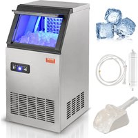
HBZB-36F - Ice machine Vevor - Free user manual and instructions
Find the device manual for free HBZB-36F Vevor in PDF.


User questions about HBZB-36F Vevor
0 question about this device. Answer the ones you know or ask your own.
Ask a new question about this device
Download the instructions for your Ice machine in PDF format for free! Find your manual HBZB-36F - Vevor and take your electronic device back in hand. On this page are published all the documents necessary for the use of your device. HBZB-36F by Vevor.
USER MANUAL HBZB-36F Vevor
Technical Support and E-Warranty Certificate www.vevor.com/support
AUTOMATIC ICE MAKER
MODEL: HBZB-36F
We continue to be committed to provide you tools with competitive price. "Save Half", "Half Price" or any other similar expressions used by us only represents an estimate of savings you might benefit from buying certain tools with us compared to the major top brands and does not necessarily mean to cover all categories of tools offered by us. You are kindly reminded to verify carefully when you are placing an order with us if you are actually Saving Half in comparison with the top major brands.
MODEL: HBZB-36F
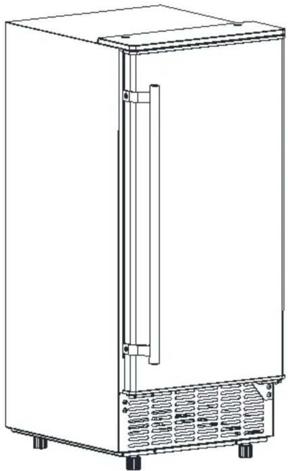
natural_image
Line drawing of a stainless steel refrigerator with ventilation grilles and side-mounted door (no text or symbols)NEED HELP? CONTACT US!
Have product questions? Need technical support? Please feel free to contact us:
Technical Support and E-Warranty Certificate www.vevor.com/support
This is the original instruction, please read all manual instructions carefully before operating. VEVOR reserves a clear interpretation of our user manual. The appearance of the product shall be subject to the product you received. Please forgive us that we won't inform you again there are any technology or software updates on our product.
CONTENTS
IMPORTANT SAFETY....3
SPECIFICATION....6
DIMENSION/ CONNECTION....6
RATING....6
GENERAL INFORMATION......7
MAIN UNIT CONSTRUCTION....7
ICE-MAKING AND ITS WATER TANK PARTS....8
OPERATION PANEL....9
EXPLOSIVE DRAWING....11
OPERATING PROCEDURE AND MAINTENANCE....14
UNPACKING YOUR ICE MAKER....14
DOOR REVERSING(Optimal)....15
INSTALLATION LOCATION REQUIREMENT....17
ELECTRICAL REQUIREMENT & CONNECTIONS......19
CLEANING YOUR ICE MAKER BEFROE FIRST USING....20
WATER CONNECTIONS FOR YOUR ICE MAKER......20
OPERATION YOUR UNIT....22
OPERATION OF ICE MAKING PROCESS....22
WIRING DIAGRAM....25
NORMAL SOUNDS....26
PREPARING THE ICE MAKER FOR LONG STORAGE....26
CLEAND AND MAINENANCE....27
EXTERIOR CLANING....28
INTERIOR CLEANING....28
ICE MAKING PARTS CLEANING....29
ICE MAKING ASSEMBLY SYSTEM CLEANING BY USING NU-CALGON
NICKLE SAFE ICE-MACHINE CLEANER....31
CLEANING SUGGESTION....33
NORMAL TROUBLE SHOOTING....34
CORRECT DISPOSAL OF THIS PRODUCT......37
IMPORTANT SAFETY
When using electrical appliances, basic safety precautions should be followed to reduce the risk of fire, electric shock, and injury to persons of property. Read all instructions before using any appliance.
Use this appliance only for its intended purpose as described in this owner's manual. This ice-maker must be properly installed in accordance with the installation instructions before it is used.
This unit must be positioned so that the plug is accessible. Do not run or over carpeting or other heat insulators. Do not cover the cord. Keep cord away from traffic areas, and do not submerge in water. No other appliance should be plugged into the same outlet, and be sure that the plug is full inserted into the receptacle.
We do not recommend the use of extension cord as it may overheat and cause a risk of fire. If you must use an extension cord, use ^2 1.5mm minimum size and rated no less than 16A/250V\~ with a plug.
If the supply cord is damaged, it must be replaced by the manufacturer its service agent or a similarly qualified person in order to avoid a hazard Disconnect the mains plug from the supply socket when not in use for a long term, where supply connection is via mains plug.
Remove power plug or disconnect from the mains before cleaning or servicing the appliance. NOTE: If for any reason this product requires service, we strongly recommend that a certified technician perform the service.
Never unplug you unit by pulling on the power cord. Always grasp the p firmly and pull straight out from the outlet.
Do not use your unit outdoors. Keep the unit away from direct sunlight a make sure that
there is at least 6 inches of space between the back of your unit and w and keep the front free. Keep ventilation opening in the appliance enclosure or in the built-in structure, clear of obstruction.
Do not tip over the unit which will cause abnormal noisy and make the ice-cube size abnormal. And seriously, it may cause water leakage from
the unit.
If the unit is brought in from outside in the winter season, give it a few to warm up to room temperature before plugging it in.
Do not use other liquid to make the ice-cube other than water.
Do not clean your ice maker with flammable fluids. The fumes can create fire hazard or explosion.
- WARNING: This appliance must be earthed. Use the proper power source according to the nameplate.
- WARNING: Keep ventilation openings, in the appliance enclosure or in the built-in structure, clear of obstruction.
- WARNING: Do not damage the refrigerant circuit.
- WARNING: This appliance is not intended for use by persons (including children) with reduced physical, sensory or mental capabilities, or lack of experience and knowledge, unless they have been given supervision or instruction concerning use of the
appliance by a person responsible for their safety.
- WARNING: Children should be supervised to ensure that they do not with the appliance.
- WARNING: This appliance must be earthed. And use the 220-240V/50I earthed power supply.
- WARNING: Do not store explosive substances such as aerosol cans with a flammable propellant in this appliance.
- DANGER – Risk Of Fire or Explosion. Flammable Refrigerant Used. D Not Use Mechanical Devices To Defrost Ice Maker. Do Not Puncture Refrigerant Tubing.
DANGER – Risk Of Fire Or Explosion. Flammable Refrigerant Used. To Repaired Only By Trained Service Personnel. Do Not Puncture Refrigeran Tubing.
- CAUTION – Risk Of Fire Or Explosion. Flammable Refrigerant Used. Consult Repair Manual/Owner's Guide Before Attempting To Install or Service This Product. All Safety Precautions Must be Followed.
- CAUTION – Risk Of Fire Or Explosion. Dispose Of Property In Accordance With Federal Or Local Regulations. Flammable Refrigerant
Used.
- CAUTION-Risk Of Fire Or Explosion Due To Puncture Of Refrigerant Tubing; Follow Handling Instructions Carefully. Flammable Refrigerant Used.
- The ice maker should be installed in accordance with the safety standard for Refrigeration Systems, ASHRAE15. The ice maker shall not be installed in corridors or hallways of public buildings.
- If the unit is with problem need to be maintained, that replacing with li components and that servicing shall be done by factory authorized service personnel, so as to minimize the risk of possible ignition due to incorrect parts or improper service.
- WARNING: Keep ventilation openings, in the appliance enclosure or in the built-in structure, clear of obstruction.
- WARNING: This appliance is intended to be used in household and similar applications such as
Eg.staff kitchen areas in shops, offices and other working environments; Eg. farm houses and by clients in hotels, motels and other residential types environments; Eg.bed and breakfast type environments;
Eg. catering and similar non-retail applications.
IMPORTANT:
The wires in this mains lead are colored in accordance with the following code: Green and yellow: Earth
Blue: Neutral
Brown: Live
As the color of the wires in the mains lead of the appliance may not correspond with the colored markings identifying the terminal in your plug proceed as follows:
The wire which is colored green-and-yellow must be connected to the
terminal in the plug which is marked with the letter E, G or by symbol or colored green or green-and-yellow.
The wire which is colored blue must be connected to the terminal which
marked with the letter N.
The wire which is colored brown must be connected to the terminal which is marked with letter L.
SPECIFICATIONS
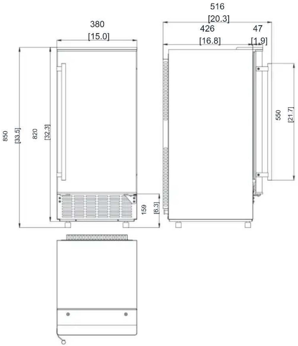
1) DIMENSIONS/CONNECTIONS
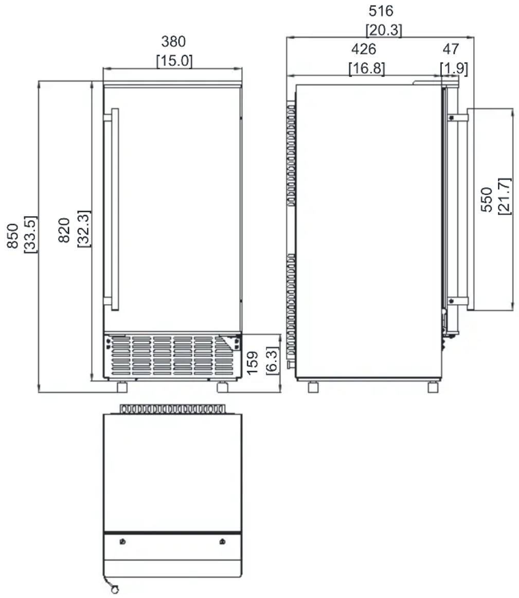
text_image
380 [15.0] 850 [33.5] 820 [32.3] 159 [6.3] 516 [20.3] 426 [16.8] 47 [1.9] 550 [21.7]2) Rating
NOTE*: TESTED AT 21°C ROOM TEMPERATURE AND 10°C WATER TEMPERATURE.
| MODEL | HBZB-36F |
| POWER SUPPLY VOLTAGE | 1Phase, 220-240V/50Hz |
| CLAIMATE CLASS | SN/N/ST/T |
| ELECTRICAL PROTECTION CLASS | I |
| ICE MAKING RATING (Amps) | 1.5 |
| ICE HARVEST RATING (Amps) | 1.9 |
| ICE MAKING CAPACITY (KG/24H) | 36 * |
| REFRIGERANT CHARGE | R290 2.29Oz / 65g |
| NET WEIGHT(lbs) | 53 |
| VESICANT | C_5H_10 |
| UNIT DIMENSIONS(W X X H) (Inch) | 15x20.3x33.5 |
| MAX ICE STORAGE CAPACITY(lbs) | 12 |
| ACCESSORIES | SHOVEL, INSTALLATION KIT,S HANDLE |
| CONNECTION | POWER CORD---- 0.75 mm2WATER SUPPLY----6.35mm DiameterDRAIN PIPE----Φ16mm SYLPHONBELLOWSS |
| RUNNING CONDITIONS | ROOM TEMP 10-43°CWATER SUPPLY TEMP 5-35°CWATER SUPPLY PRESSURE 0.04-0.6 M |
GENERAL INFORMATION
1) Main Unit Construction
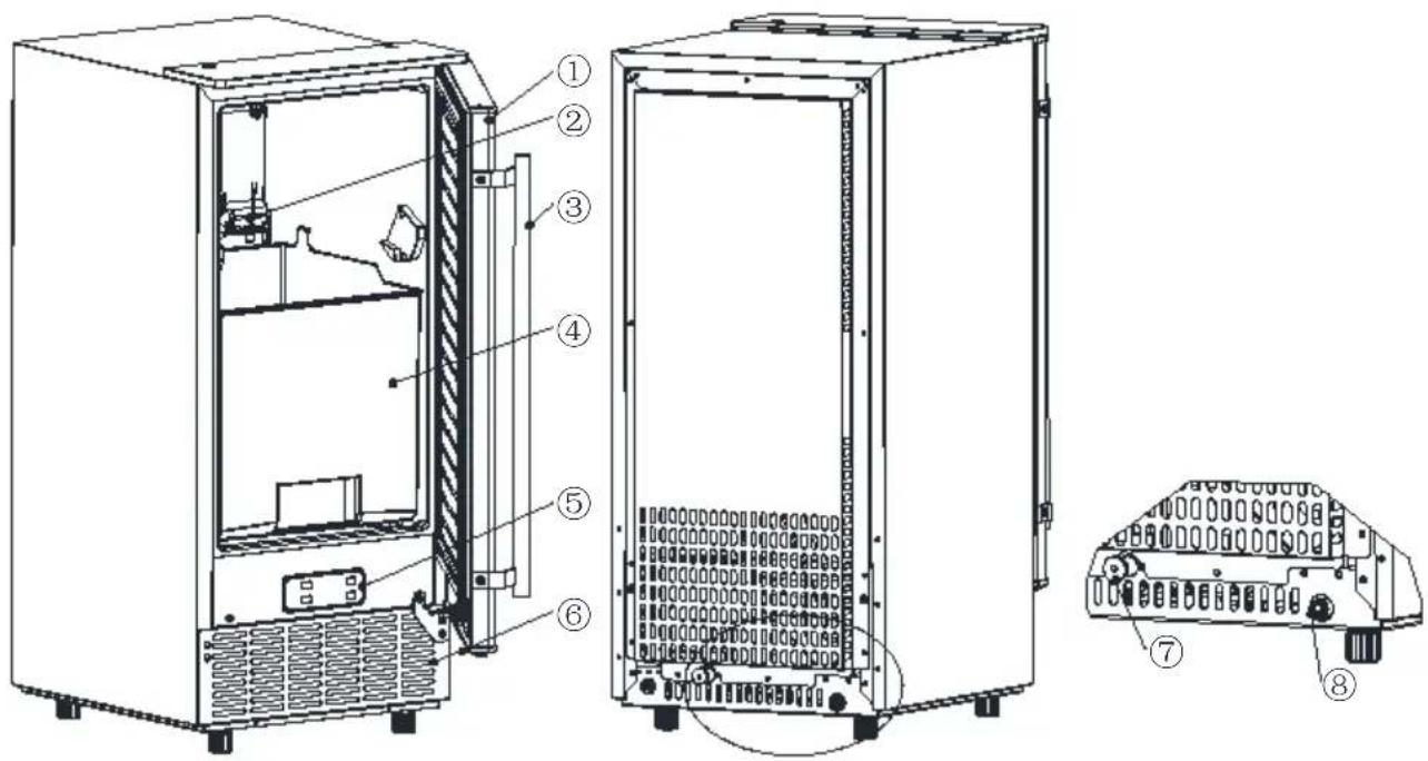
text_image
Technical diagram of an internal device with numbered components, showing exploded and assembled views- Door
- Ice-making & its water tank assembly: Including ice-making evaporator, water tank, water pump and some detecting parts
- Handle
- Ice tank
- Operation panel
- Air outlet: Must keep the air circulate smoothly, hot air will blow out with unit running.
- Water draining port: Normal plugged with the cap. When need to drain the water, unplug the cap. And connect the gray drain pipe.
- Water inlet port for water supply: Use to connect the water supply pipe. Accessory: 2 meters long water drain pipe water quick connector of the water faucet 6.35mm diameter and white color water supply pipe (3 meters long).
2) Ice-making and its water tank parts
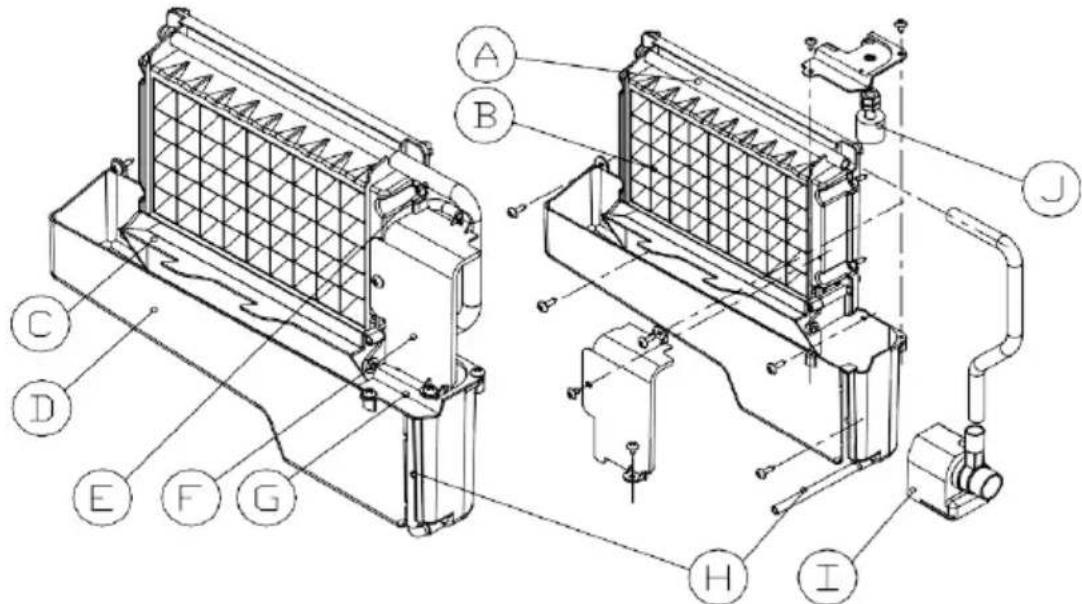
text_image
Technical diagram of a mechanical assembly with labeled components A through J, showing structural details and connections.A. Water dividing pipe: with nine little holes, water will flow out from these little holes. And if no water flows out, can be disassembled and cleaned.
B. Evaporator (ice-making module)
C. Ice full detecting board: Use to detect the inner cabinet is full of ice or and to check the the ice-harvest process is over or not.
D. Water tank:
E. Water supplying pipe:
F.Cover board on the right side of the evaporator:
G.Water level switch installing plate:
H. Water drain pipe of the water tank: when ice-making, this pipe should clamped in the slot of the water tank wall; And when draining, this pipe should be pulled out.
I. Water pump:
J. Water level detecting switch
3)Operation panel
A. "TIMER CLEAN" button: Quickly press this button once, to enter the Timer setting program; And press this button for more than 5 seconds, to enter the Cleaning program.
B. “ON/OFF”button:
When the unit is off, press this button to turn on the unit; And during th
Self-cleaning program, or normal ice-making state, press this button to turn off the unit at once; And also if the unit is set with the Timer, pres button to cancel the Timer setting. When the unit is making the ice cube press this button for more than 5 seconds, the unit will switch to ice hair process by force.
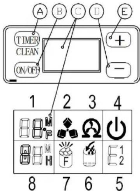
text_image
A B C D E TIMER CLEAN ON/OFF + - 1 2 3 4 8 7 6 5C.LCD display window
-
Environmental temperature display and ice-making time countdown display. Display ice-making time countdown with M as the unit display, and display environmental temperature with F as the unit display.
-
Making ice and deice symbol display, the machine is making ice when the symbol rotated, and the machine is deicing when the symbol flash.
-
Automatic self-cleaning symbol display
-
On/off symbol display
-
Error code display: E1 means the environmental temperature sensor is damaged. E2 means ice making anomaly or the refrigerant leaked.
-
Water flow in and water shortage display, the arrow flashing indicates that the machine is in the water, the whole symbol is bright to indicate that the machine is short of water.
-
Ice full alarm, the machine will making ice again when you take out the ice.
-
Setting display: Display timing switch machine with the H as unit displa
Display ice making time setting with M as unit display.
D&E. “+”/”-”button: Use to adjust the ice-making process duration period
length, the default setting is zero, 1 minute adding or decreasing per each pressing of “+” or “-” button.
Also to adjust the delay time of the timer, the default setting is zero, 1 adding or decreasing per each pressing of “+” or “-” button.
4)EXPLOSIVE DRAWING
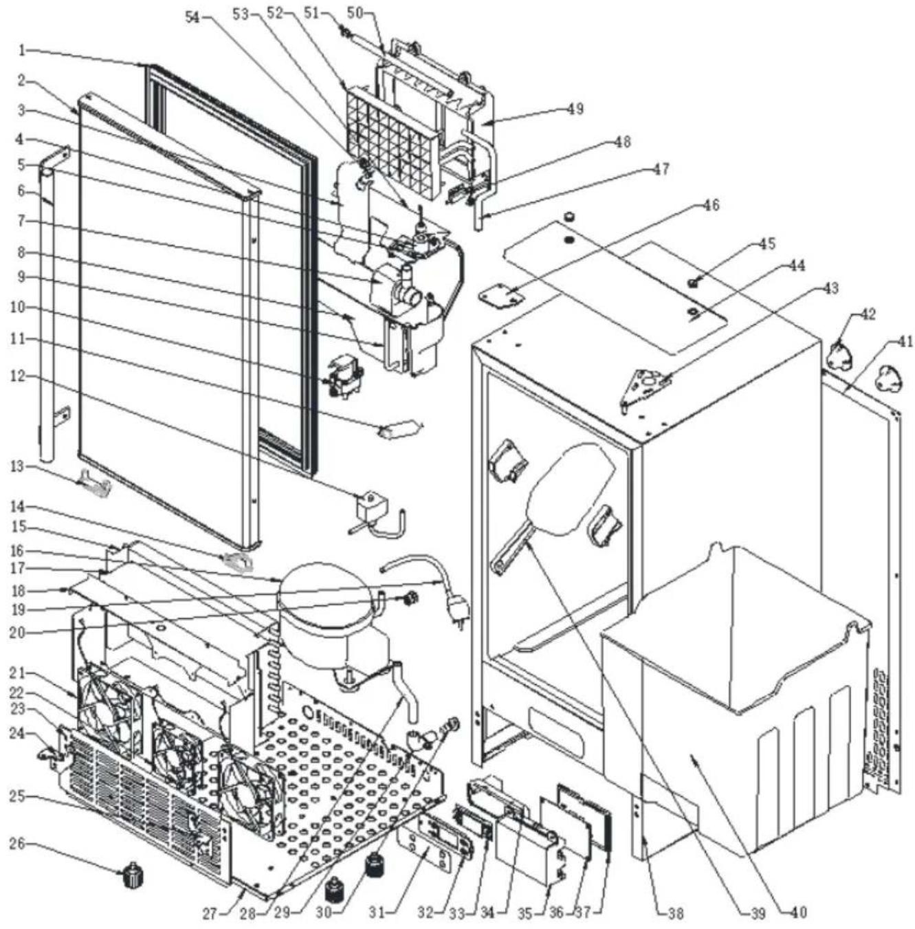
text_image
Exploded view diagram of a refrigerator internal components with numbered labels| NO. | Part Name | Specifications | Qty |
| 1 | Door seal | PVC | 1 |
| 2 | Door | SUS & Foams | 1 |
| 3 | Water tank side cover | ABS White | 1 |
| 4 | Float switch | Electrical part DC5V | 1 |
| 5 | Water tank cover | ABS White | 1 |
| 6 | Handle | SUS | 1 |
| 7 | Pump | Electrical part AC230V | 1 |
| 8 | Water Tank | ABS White | 1 |
| 9 | Drain tube for water tank | Silicone tube,FDA | 1 |
| 10 | Water inlet solenoid | Electrical part DC12V | 1 |
| 11 | Filter Dryer | Copper and dryer | 1 |
| 12 | Solenoid valve for ice release | Electrical part AC230V | 1 |
| 13 | Left fix piece | POM | 1 |
| 14 | Right fix piece | POM | 1 |
| 15 | Condenser | Copper and aluminum | 1 |
| 16 | Compressor & accessory | Electrical part AC230V | 1 |
| 17 | Fan fix plate | Zinc-Plate sheet δ=0.8 | 1 |
| 18 | Fan fix cover plate | Zinc-Plate sheet δ=0.6 | 1 |
| 19 | Plug +Power cord | Electrical part | 1 |
| 20 | Strain relief bushing | PP black | 1 |
| 21 | Fan | Electrical part DC12V 120mm | 2 |
| 22 | Fan | Electrical part DC12V 90mm | 1 |
| 23 | Air outlet panel | SUS430 δ=0.8 | 1 |
| 24 | Left bottom hinge | SPCC δ=2.5mm Chrome Plated | 1 |
| 25 | Right bottom hinge | SPCC δ=2.5mm Chrome Plated | 1 |
| 26 | Adjusted foot | M8*30mm | 4 |
| 27 | Bottom plate | Zinc-Plate sheet δ=1.2 | 1 |
| 28 | Drain tube on liner | Silicone tube,FDA | 1 |
| 29 | Water drainage port | ABS Gray,FDA | 1 |
| 30 | Water drainage cap | Rubber Black | 1 |
| 31 | Operation panel paper | PET,thickness 0.25mm | 1 |
| 32 | Operation panel PCB fix board | ABS Black | 1 |
| 33 | Operation panel PCB | Electrical part DC5V | 1 |
| 34 | Operation panel PCB box | ABS Black | 1 |
| 35 | Main PCB box | ABS 5V Black | 1 |
| 36 | Main PCB | Electrical part AC230V | 1 |
| 37 | Main PCB cover | ABS 5V Black | 1 |
| 38 | Foaming cabinet | Sheet metal +foams | 1 |
| 39 | Ice scoop | ABS White | 1 |
| 40 | Ice basket | PP White | 1 |
| 41 | Back-cover plate | Zinc-Plate sheet δ=0.6 | 1 |
| 42 | Back support column | PP black | 4 |
| 43 | Top hinge | SPCC δ=2.5mm Zinc-plated | 1 |
| 44 | Top cover | ABS Black | 1 |
| 45 | Screw hole cover | ABS Black | 1 |
| 46 | Fix plate | SPCC δ=2.5mm Zinc-plated | 1 |
| 47 | Water outlet tube form pump | Silicone tube,FDA | 1 |
| 48 | Magnet switch | Electrical part DC5V | 1 |
| 49 | Evaporator frame | ABS White | 1 |
| 50 | Water dividing pipe, eight holes | ABS White | 1 |
| 51 | Cap of the water dividing pipe | Silicone,FDA | 1 |
| 52 | Evaporator | Copper Nickle plated | 1 |
| 53 | Ice full detecting plate | ABS White | 1 |
| 54 | LED light | Electrical part DC5V white light | 1 |
-
Remove the exterior and interior packaging. Check if all the accessories are inside or not including the instruction manual, ice scoop, white water inlet pipe, the water draining pipe, the quick connector (connecting a 1/4-inch connector with a 1/2-inch one), etc. If any parts are missing, please contact our customer service.
-
Remove the tapes for fixing the door and inner cabinet, ice scoop, etc. Roughly clean the inner cabinet & ice scoop with wet clothe.
3.Put the ice maker on a level & flat floor, without direct sunlight and ot
sources of heat (i.e.: stove, furnace, radiator). Make sure that there is at least 50cm gap between the air outlet and the obstacles, and at least 5 cm between the wall.
- Allow 4 hours for the refrigerant fluid to settle before plugging the ice maker in if the unit maybe fall upside down during shipping or transportation.
- The appliance must be positioned so that the plug is accessible.
WARNING: connect to the potable water supplying only. Only use drinking water.
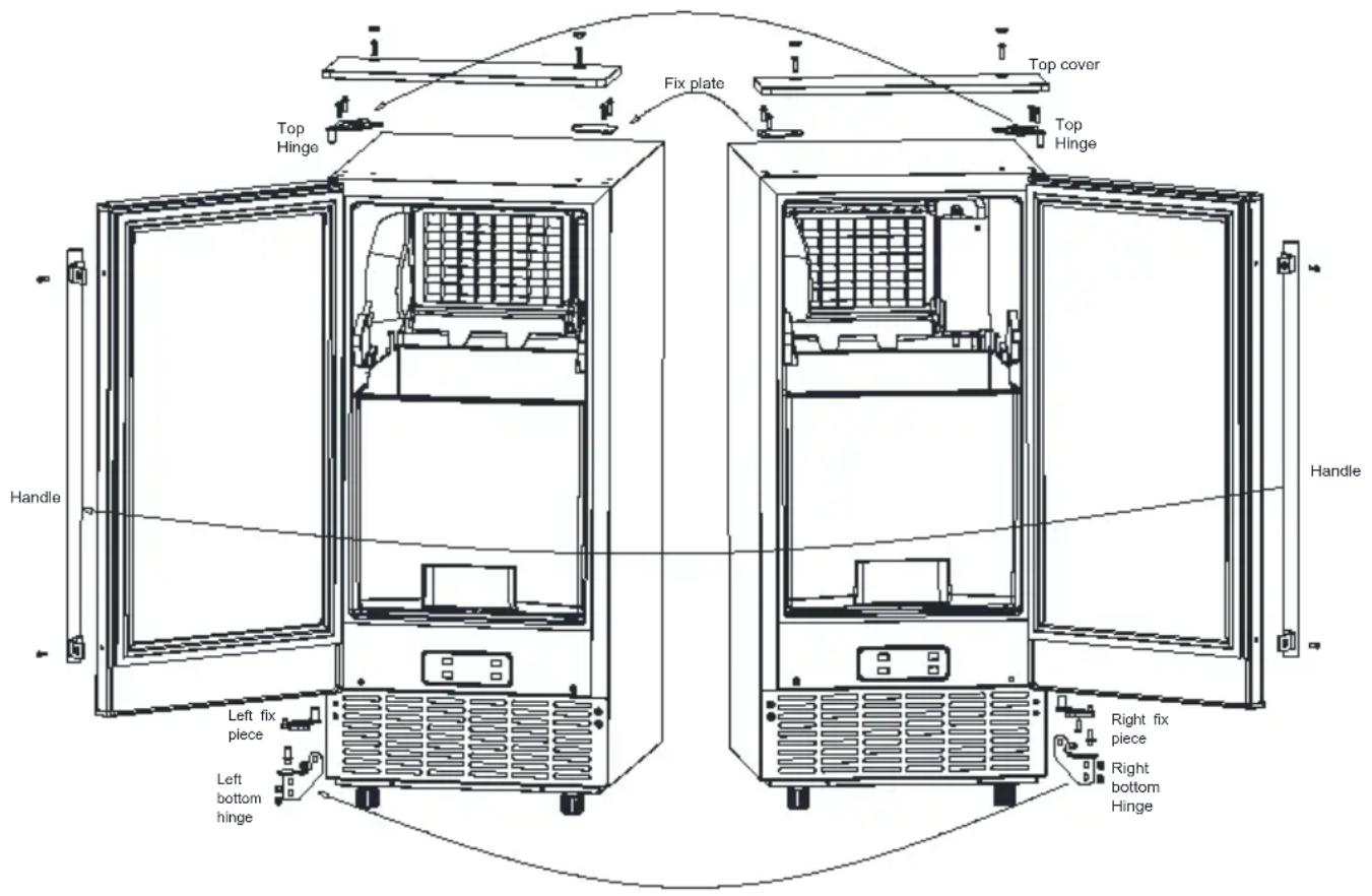
DOOR REVERSING (Optional)
If you want the ice maker's door to open from the opposite side, you can reverse the door swing.
text_image
Top Hinge Fix plate Top cover Top Hinge Handle Right fix piece Right bottom Hinge Left fix piece Left bottom hinge- Ensure the unit is unplugged before starting door reversal.
- Remove the 2 Screw hole cover on the top cover, unscrew two screw
which is fix the top cover.
- Remove the 2 screws from the top hinge, and 2 screws from the fix plate.
- Lift the door up and take off the door.
- Set the freezer door on a non-scratching surface with the outside up.
- Release the 2 screw on the handle, fix on the opposite side of the door.
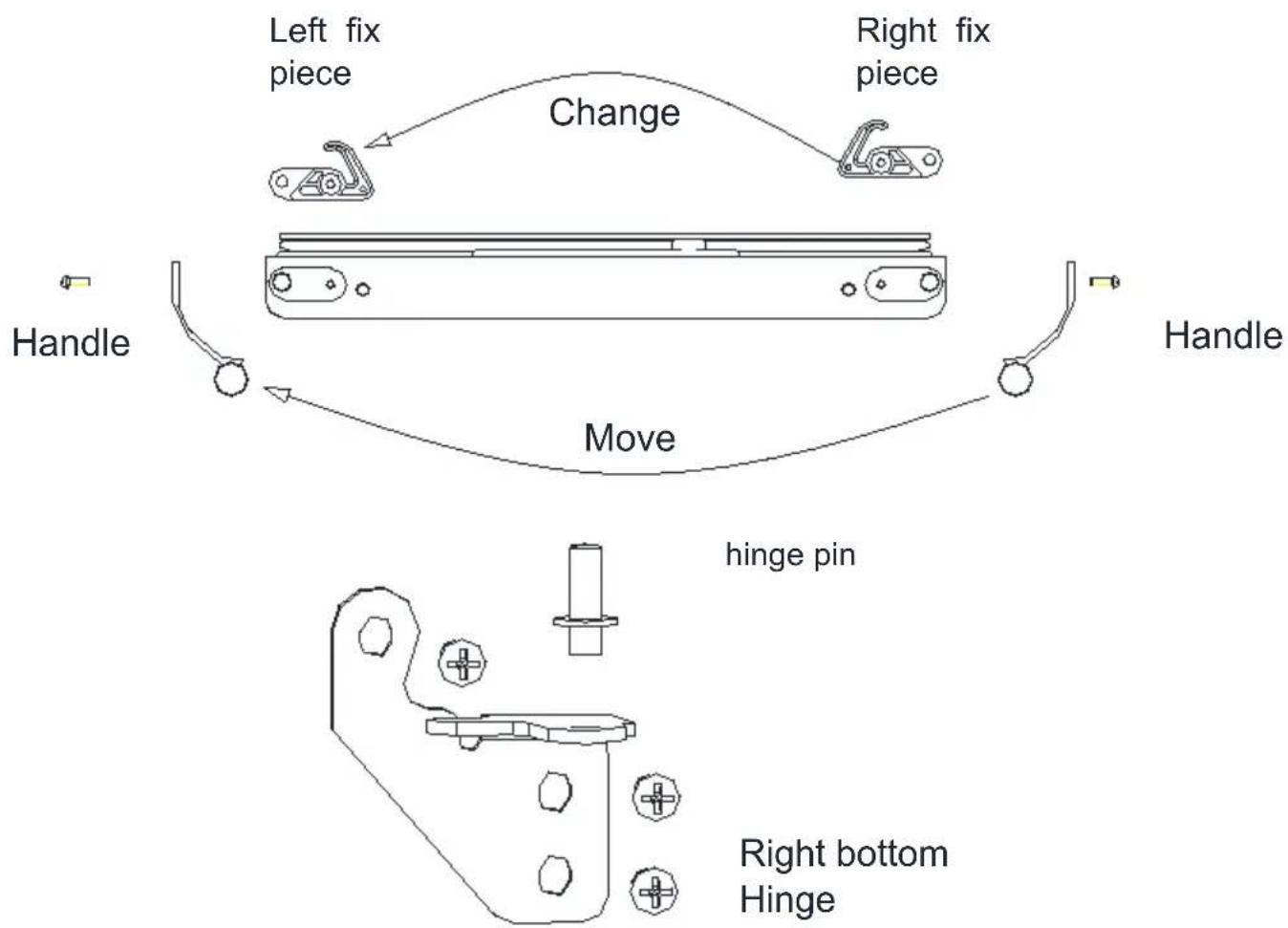
Remove the screw on the right fix piece, fix the left fix piece (from accessory bag) to the door.
flowchart
graph TD
    A["Handle"] --> B["Left fix piece"]
    B --> C["Change"]
    C --> D["Right fix piece"]
    D --> E["Handle"]
    E --> F["Move"]
    F --> G["hinge pin"]
    G --> H["Right bottom Hinge"]
- Remove the right bottom hinge by removing the 3 screws, then fix the 3 screw back without hinge.
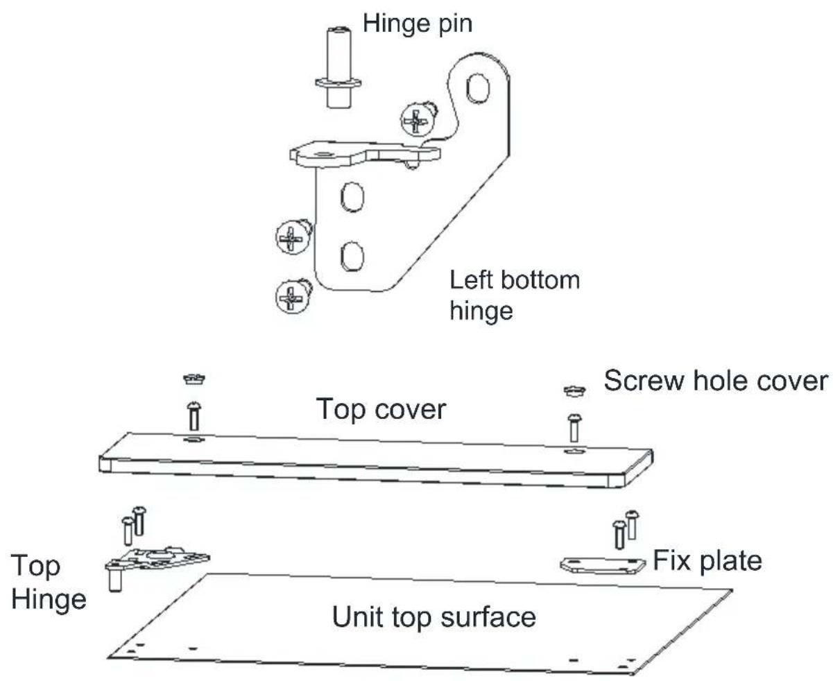
- Remove the hinge pin on the right bottom hinge and reinstall on the left bottom hinge.
- Remove the 3 screws from the left side and fix the left bottom hinge on the unit.
- Place the door on the left bottom hinge. With the magnetic gasket holding the door in place, make sure the door is aligned with the unit, and
secure the top hinge on the left with 2 screws.
- Open and close both the door several times to confirm the door is positioned correctly and the gasket is sealed well. If this is not the case, please adjust the door again.
- Fix the Fix plate back on the right side. Fix the top cover with 2 screw, cover the screw hole with the Screw hole cover.
- Wait at least 30 minutes before plugging in the refrigerator to allow the refrigerant to settle down. Then plug in the unit.
text_image
Hinge pin Left bottom hinge Top cover Screw hole cover Top Hinge Fix plate Unit top surfaceINSTALLATION LOCATION REQUIREMENT
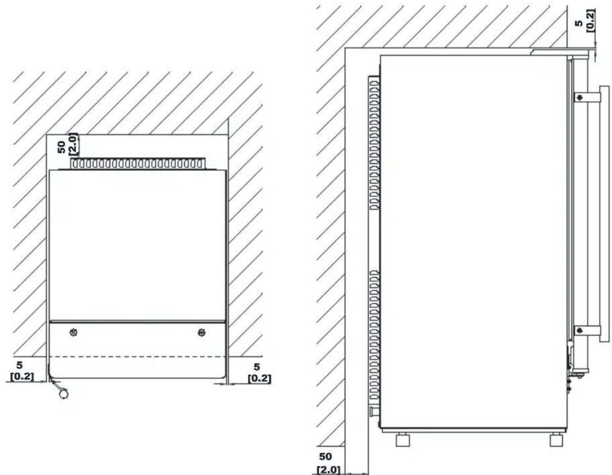
a)This unit is not for outdoor use. Keep the proper room temperature and inlet water temperature according to above specification table. Otherwise it will affect the ice making performance.
b)This unit should not be located near any heat resource.
c) The unit should be located on a firm & level foundation at normal court top height.
d) There must be at least a 2-inch clearance at rear side for connection with a 10-inch clearance in the front to open the door and keep good air circulation.
e) Do not put anything on the top of the ice maker.
Installation clearance top view (mm)
Side view (mm)
text_image
50 [2.0] 5 [0.2] 5 [0.2] 50 [2.0]To ensure proper ventilation for your ice maker, the front of the unit must completely unobstructed (at least a 16-inch free space). Allow about 0.2 inches clearance at rear, and 0.2 inches at top for proper air circulation. The installation should allow the ice maker to be pulled forward for servicing if necessary.
When installing the ice maker under a counter, follow the recommended spacing dimensions shown above. Place electrical and water supplies and drain fixtures in the recommended locations as shown.
Choose a well-ventilated area with temperatures above 50 °F and below 90 °F. This unit MUST be installed in an area protected from the element such as wind, rain, water spray, or drips. The ice maker requires a continuous water supply with 1-8 bar pressure as required in above specification table. The temperature of the water feeding into the ice mak should be between 41°F and 77°F for proper operation.
ELECTRICAL REQUIREMENT & CONNECTIONS
WARNING: THIS UNIT MUST BE EARTHED.
Electrical Shock Hazard
Plug into a grounding wall outlet.
Never remove the ground prong.
Use separate power supply or receptacle. Never use an adapter.
Never use an extension cord.
Failure to follow these instructions can result in death, fire, or ele shock.
Before you move your ice maker into its final location, it is important to make sure you have the proper electrical connection.
It is recommended that a separate circuit, serving only your ice maker, b provided. Use receptacles that cannot be turned off by a switch or pull chain. If the supply cord or plug to be replaced, it should be done by a qualified service engineer.
This appliance requires a standard 220-240Volt, 50Hz electrical outlet with good grounding means.
Recommended grounding method
For your personal safety, this appliance must be properly grounded. This appliance is equipped with a power supply cord having a grounding plug. To minimize possible shock hazard, the cord must be plugged into a ma grounding-type wall receptacle, grounded in accordance with the National
Electrical Code and local codes and ordinances. If a mating wall receptacle is not available, it is the personal responsibility of the customer to have properly grounding wall receptacle installed by a qualified electrician.
CLEANING YOUR ICE MAKER BEFROE FIRST USING
Before using your ice maker, it is strongly recommended to clean it thoroughly.
- Open the ice getting door.
- Clean with diluted detergent, warm water and a soft cloth.
-
Repeatedly clean the water contacting inner parts, you can pull the Wa drain pipe of the water tank indicating "H" in above illustration to drain the cleaned water in the water tank, then next to clean inner ice-storing cabi till all of inner parts are cleanly, then drain out all of the cleaned water the water drain port located at unit back indicating "7" in above illustration And must to reinstall back the water drain pipe of the water tank and the cap of the unit water drain port, otherwise, the unit will not make the ice normally. And suggest that you should discard the
ice-cube made by the first ice making cycle after cleaning. -
The outside of the ice maker should be cleaned regularly with a mild detergent solution and warm water.
-
Dry the interior and exterior with a clean soft cloth.
WATER CONNECTION FOR YOUR ICE MAKER
Important: Be sure to use the new hose-sets supplied with the appliance to connect to water mains and that old hose-sets should not be reused.
1. Connect the water supplying hose to the unit
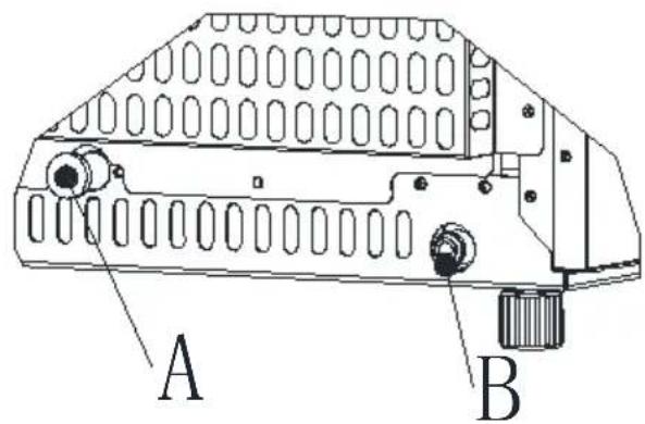
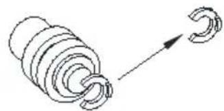
Step 1: First remove the tape on the water inlet port for water supply (indicated in the following illustration “B”) located at unit back, then use your other hand’s finger to press the out circle
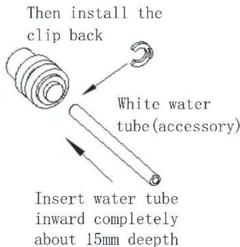
Step 2: Insert the one end of the white water hose into the water inlet, and push inward completely, and install back the clipper, then water hose connection is completed.
STEP 1: Remove the tape
text_image
A BWater inlet port on the unit back
natural_image
Diagram of a coiled spring with an arrow indicating direction (no text or symbols)Remove the clip first
STEP 2: Insert the water tube
text_image
Then install the clip back White water tube (accessory) Insert water tube inward completely about 15mm depthNote*: When installing the water inlet pipe, it is highly recommended to use the water source which is filtered, as it benefits the taste and cleanliness of the machine and extends the lifespan of the equipment.
2. Connecting the water drain pipe
Pull out the water drainage cap with black color (indicated A in above illustration), then connect the white drainage pipe included in accessory, again connect the other end of this drainage to the main water drainage pipeline.
3. Connect the water hose to the water faucet of the water main supply system
First, install the supplied water quick-connector to the water faucet by screw thread; Second, remove the clipper from the water quick-connector, insert the another end of the water hose into this quick-connector port
completely, then install back the clipper, also this step is completed. Note The water faucet should be supplied by the customer himself.
Important: The water pressure of main water supply system must be 0.04-0.6 MPa at least.
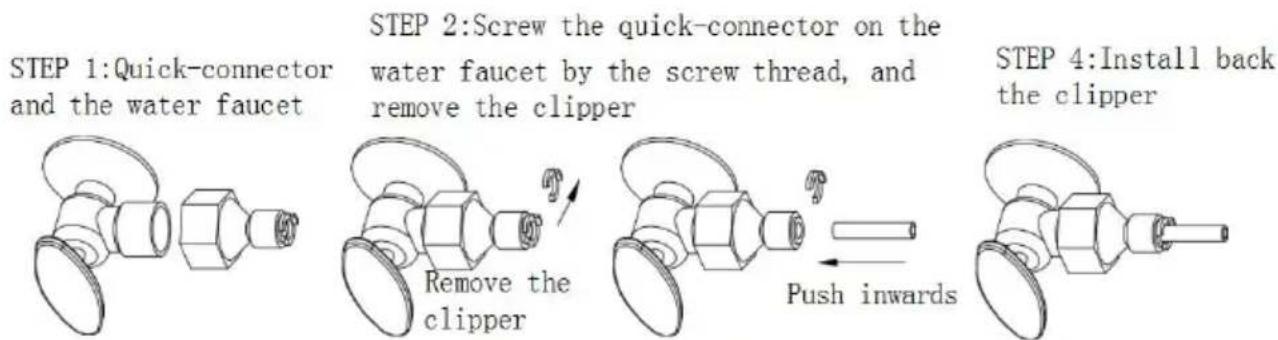
flowchart
graph LR
    A["STEP 1: Quick-connector and the water faucet"] --> B["STEP 2: Screw the quick-connector on the water faucet by the screw thread, and remove the clipper"]
    B --> C["STEP 4: Install back the clipper"]
    C --> D["Push inwards"]
STEP 3: Insert the water hose completely
OPERATION YOUR UNIT
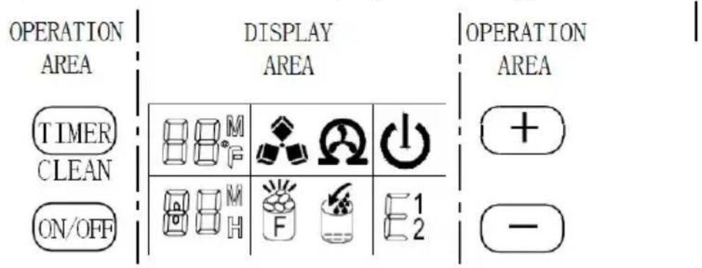
Operation button and display area diagram
text_image
OPERATION AREA TIMER CLEAN ON/OFF DISPLAY AREA OPERATION AREA + - +- Start up: Plug in the power plug, and the symbol will flash in the display window. Press the ON/OFF button on the control panel. The machine will start to make ice when the external pipe adds water to reach the stand level on the water tank through the electromagnetic water valve. Thereafter
the symbol will remain bright constantly in display window and
symbol will rotate. The ambient temperature will be displayed on the upper left of the display window. “80°F” means the ambient temperature is 80°F.
Several minutes later, the flashing numbers will be displayed in the ambient temperature display area, and the flashing number "10M" means the unit still needs 10 minutes to finish this ice making cycle.
- When the ice making cycle finishes, the unit enters deicing process, an the symbol flashes. Next, the external pipe adds water to the water
tank through the electromagnetic valve, and the arrow on the symbol will
flash until the water reaches the standard level. Finally, the symbol extinguishes, and the unit enters the next ice making cycle. When the
water cannot reach the standard level, the symbol is always bright, and the unit stops working. Restart the unit if there is a shortage of water; otherwise it will start up automatically after 15 minutes.
Note: Each ice making cycle lasts between 11 and 20 minutes. The ice making time varies according to the changes of ambient temperature and the water temperature, especially in the first ice making cycle. The ice making cycle will be longer because of the high water temperature in the water tank, but it will not exceed 30 minutes.
- Adjust the ice thickness: Press the “+” and “-” button on the control pad to adjust the ice thickness. The number in the left bottom of the display window is the setting of the ice making time, and the default setting is “To produce thicker ice, add one minute of ice making time by pressing ‘button once; in contrast, to produce thinner ice, reduce one minute of ice making time by pressing "-" once. Restart the machine and it will go back the default setting of “0”.
Note: The time currently set only changes the next and the subsequent i making cycles.
- When the symbol lights up, the machine stops working, and it will work again after you take out the ice.
5.Shut down the unit: During the ice making process, press the "ON/OFF
button on the control panel to shut down the unit and the unit enters the standby mode. If you press "ON/OFF" longer than 5 seconds during ice making process, then the unit enters the deicing process directly. This function can help remove the ice on the ice plate. Press "ON/OFF" to shift down the machine.
6. Timing setting: Setting range: 1-24 hours
Time shutdown: When the unit is running, it can set up the timing shutdown. Time on: When the unit is on standby, you can set the unit with ON-TIM. How to set up the timing
Press the TIMER button, the default timing time is "1H" in display window, then press "+" button to adjust the timing time you need, every time you press the "+" button, the time add 1 hour. Press "-" button can reduce the timing time. During the process of time adjustment. The "H" in the lower corner of the number will flash, then after 5 seconds flashing without pressing, the "H" letter will change from flashing to always displaying, means the timer program has been completed.
In standby condition display 5H, it means the unit will start automatically after 5 hours; In ice making condition display 5H, it means the machine with shut down automatically after 5 hours, the "H" in the display screen indicates that the machine currently has timing function, and the number front will be smaller and smaller. Until it becomes zero, the timing ends, and the machine enters the mode you need.
How to cancel timing
When the unit has a timing (the display window will display XX H), press "TIMER" button, the timing is canceled after the number on the screen and "H" are extinguished.
When the unit has a timing, the display area in the lower left corner will display the timing time and the ice making setting time, and the display content will be switched every 5S.
7. Automatic self-cleaning program. The default cleaning time is 20 minutes.
Start the self-cleaning program: After connecting all of the water pipe, plug on the main power supply plug, then press "TIMER CLEAN" button on
control panel for more than 5 seconds, to enter the self-Cleaning program, the symbol 📁 rotate on display screens. Time count down area display 20M. And the “CLEAN” light will always be on during this period, the digit window will indicate the left time, the water pump runs for 8 minutes and stops for 3 minutes, always recycle. The total duration time is 20 minutes for one self-cleaning program. Also when the water pump stops, the water will supply to the water tank automatically.
Cancel the self-cleaning program: It takes about 20 minutes to complete one self-cleaning program. When the program is over, the system will be in off-state automatically. And also you can press the “ON/OFF” button on control panel to cancel the self-cleaning program by force.
- How to switch Fahrenheit(°F) to Celsius(°c)?
Press +"or"- "button longer than 5s, It will automatically switch.
WIRING DIAGRAM

flowchart
graph TD
    A["Main Control PCB"] --> B["DC Fan M otor"]
    A --> C["Power Supply"]
    A --> D["Main Control PCB"]
    D --> E["MCU"]
    D --> F["LCD"]
    D --> G["Electrical Diagram"]
    D --> H["Start Relay"]
    D --> I["Overload Protector"]
    D --> J["AC -N"]
    D --> K["AC-L"]
    D --> L["COM P"]
    D --> M["PUMP"]
    D --> N["AC W ater Pump p"]
    D --> O["Solenoid Vale for Ice-harvest"]
    D --> P["Relay"]
    D --> Q["AC Drain Pump"]
    D --> R["DC Water Inlet Valve"]
    D --> S["Water Level Detec ting Sw itch"]
    D --> T["Swnor For Am bient Tem p"]
    D --> U["Sensor For Ice Full Decettor"]
    D --> V["Sensor For D rain Level Detector"]
    D --> W["ICU"]
    D --> X["ICE"]
    D --> Y["S1"]
    D --> Z["T1"]
Normal Sounds
Your new ice maker may make sounds that are not familiar to you. Mos the new sounds are normal. Hard surfaces like the floor, walls and cabin can make the sounds seem louder than they actually are. The following describes the kinds of sounds that might be new to you and what may making them.
- You will hear a swooshing sound when the water valve opens to fill the water tank for each cycle.
- Rattling noises may come from the flow of the refrigerant or the water items stored on top of the ice maker can also make noises.
- The high-efficiency compressor may make a pulsating or high-pitched sound.
- Water running from the water tank to the evaporator plate may make a splashing sound.
- Water running from the evaporator to the water tank may make a splashing sound.
- As each cycle ends, you may hear a gurgling sound due to the refriger flowing in your ice maker.
- You may hear air being forced over the condenser by the condenser for. During the harvest cycle, you may hear the sound of ice cubes falling in the ice storage bin.
- When you first start the ice maker, you may hear water running continuously. The ice maker is programmed to run a rinse cycle before it begins to make ice.
Preparing the Ice Maker for Long Storage
If the ice maker will not be used for a long time, or is to be moved to another place, it will be necessary to drain out all of the water in the system.
- Allow all of the ice cubes have been ejected from the evaporator of ice maker.
-
Turn off the unit, and unplug the power cord.
3.Shut off the water supply at the main water supply. -
Disconnect the water supply hose from the water inlet valve.
- Pull out the Water drain pipe of the water tank indicating “H” in above illustration to drain out the water in the water tank. When all of the water has been drained out, to reinstall back the water drain pipe of the water tank.
- Then drain out all of the water from the water drain port located at un back indicating “7” in above illustration.
- Disconnect the water drain pipe to the main drain pipeline or floor drain plug on the drain cap again.
- Drop the door open to allow for circulation and prevent mold and milde
- Leave water supply hose and power cord disconnected until ready to reuse.
- Dry the interior & wipe the outside of the unit.
- Put a plastic bag on the unit to resist out dust & dirty.
CLEANING & MAINTENANCE
WARNING: Before carrying out any cleaning or maintenance operations, unplug the ice maker from the main power supply electricity. (EXCEPTIOI Ice maker self-cleaning program).
Do not use any alcohol or fume for cleaning/sanitization of the ice maker may cause cracks on the plastic parts.
Ask a trained service person to check and clean the condenser at least once a year, in order to let the unit work properly.
This appliance must be cleaned by use of a water jet.
| CAUTION |
| If the ice maker has been left unused for a long time, before the use it must be thoroughly cleaned. Follow carefully any instructic provided for cleaning or use of sanitizing solution. Do not leave solution inside the ice maker after cleaning. |
Periodic cleaning and proper maintenance will ensure efficiency, top performance, hygienic, and long life. The maintenance intervals listed are based on normal conditions. You may want to shorten the intervals if you have pets, or the unit is used outdoors, or there are other special considerations.
What shouldn't be done
Never keep anything in the ice storage bin that is not ice: objects like w and beer bottles are not only unsanitary, but also it's labels may slip off obstruct the drain pipe.
Exterior Cleaning
The door and cabinet may be cleaned with a mild detergent and warm water solution such as 28g of dish washing liquid mixed with 7.5L of wa water. Do not use solvent-based or abrasive cleaners. Use a soft sponge and rinse with clean water. Wipe with a soft clean towel to prevent water spotting.
Stainless steel models can discolor when exposed to chlorine gas and should be cleaned. Clean stainless steel models with a mild detergent and warm water solution and a damp cloth. Never use abrasive cleaning agents.
NOTICE: Stainless steel models exposed to chlorine gas and moisture, such as in areas
with spas or swimming pools, may have some discoloration of stainless steel. Discoloration from chlorine gas is normal.
Interior Cleaning
For Ice Storage Bin
The ice storage bin should be sanitized occasionally. Clean the bin before the ice maker is used for the first time and reused after stopping for an extended period of time. It is usually convenient to sanitize the bin after ice making system has been cleaned, and the storage bin is empty.
-
Disconnect power to the unit.
-
Open the door and with a clean cloth, wipe down the interior with a sanitizing solution made of 28g of household bleach or chlorine and 7.5L hot water (95°F to 115°F).
- Rinse thoroughly with clear water. The waste water will be drained out through the drain pipe.
- Reconnect power to the unit.
The ice scoop should be washed regularly. Wash it just like any other for container.

WARNING
DO NOT use solvent cleaning agents or abrasives on the interi These cleaners may transmit taste to the ice cubes, or damage discolor the interior.
Ice Making Parts Cleaning
During the using, periodically to clean these main system of your ice-maker.
- Repeat above step to clean the water tank and other inner parts of the unit.
- Especially, to the water dividing pipe on the evaporator, when the compressor and the water pump run normally, but if there is no water flowing out from the water dividing pipe or the water flowing is very small please discharge this water dividing pipe to clean carefully. Clean each little holes on the water dividing pipe displayed in the following illustration make sure each hole is not clogged by something, then install back to the original location.

text_image
Little holes of water dividing pipe Water dividing pipe Evaporator Pull up first Then move out right toward- When there are ice cubes on the surface of the evaporator, but can't find down easily, do not use the mechanical substance to remove it by force; Only press the "ON/OFF" button for more than 5 seconds, the unit will enter the ice melting process, after some while, the big ice-cubes will fall down, then turn off the unit and unplug the power cord to clean the surface of the evaporator.
text_image
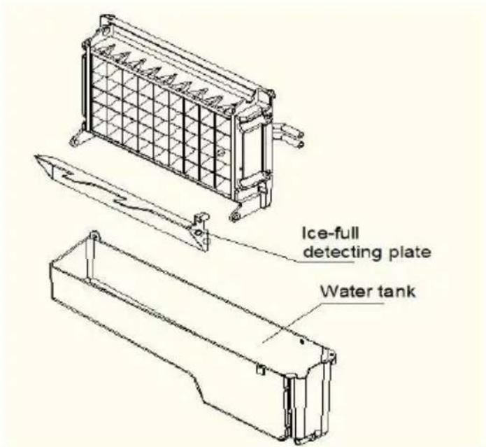
Ice-full detecting plate Water tank- For the water tank and ice-full detecting plate
Also the water tank and the ice-full detecting plate is very important to k your ice cube hygienic. Put mixture of neutral cleaner & water into a cle
water jet, then spray to all the inner surface of tank & the ice detecting Wipe these surfaces as far as possible with a clean cloth. And then, spr the surfaces with clean water, wiping with a dry clean cloth. Then drain the cleaned water in the water tank by pulling out the Water drain pipe the water tank indicating “H” in above illustration. When all of the clean water has been drained out, to reinstall back the water drain pipe of the water tank.
Suggestion: After cleaning the interior parts and install back to its respective position, and return machine to work, discard first batch of ice.
Ice Making Assembly System Cleaning by Using Nu-Calgon Nickle Safe Ice-machine Cleaner
Minerals that are removed from water during the freezing cycle will eventually form a hard scaly deposit in the water system. Cleaning the system regularly helps remove the mineral scale buildup. How often you need to clean the system depends upon how hard your water is. With h water of 4 to 5 grains/liter, you may need to clean the system as often every 6 months.
natural_image
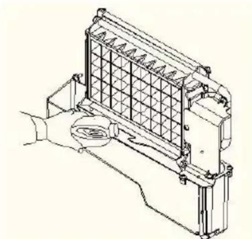
Technical line drawing of a mechanical component with grid structure and handle (no text or symbols)- Turn off the ice maker. Keep the ice maker connect to the water supp and drainpipe. But shut off the water faucet of main water supply.
2.Open the door and scoop out all of the ice cubes. Either discard them save them in an ice chest or cooler.
- Making the cleaning solution. Please mix the Nu-Calgon Nickle Safe Ice Machine Cleaner with water to make the cleaning solution.

WARNING
Wear rubber gloves and safety goggles ( and/or face shield)whehanding Ice Machine Cleaner or sanitizer.
Use a plastic or stainless container with more than 4 liters capacity, mix 300 ml Nu-Calgon Nickle Safe Ice-machine Cleaner with 2.8 liters warm water about 120^ F - 140^ F . Then divide them for 2 shares equally in 2 cups. It is better to keep the temperature of each cup of the cleaning solution.
-
Check to be sure that the water drain pipe of the water tank has been installed properly in the slot of the tank wall. Then Pour one cup of Nickel-Safe Ice Maker Cleaning Solution into the water tank. Wait about 15 minutes.
-
Turn on the power to the ice maker, then press "TIMER CLEAN" button control panel for more than 5 seconds, to enter the self-Cleaning program. Same as above explanation, the water pump runs for 8 minutes and stop for 3 minutes, one cycle, again one cycle. The total duration time is 30 minutes for one self-cleaning program.
During this process, the “CLEAN” light will always be on during this period and the digit window will indicate the remain time.
-
After 30 minutes of one self-cleaning program completing, pull out the drain pipe of the water tank, drain the cleaning solution down to the low ice storage bin. Shake the unit slightly to drain out all of the cleaning solution completely. Then install back the drain pipe to the slot of the water tank.
-
Repeat steps 4--6 to clean the ice making assembly system again.

WARNING
The ice machine cleaner contains acids.
DO NOT use or mix with any other solvent-based cleaner produce rubber gloves to protect hands. Carefully read the material instructions on the container of the ice machine cleaner.
- Then open the water faucet of the main water supply, Let the water flow in the unit. Again press the "TIMER CLEAN" button on control panel for more than 5 seconds, to enter the self-Cleaning program. Same as above explanation, the water pump runs for 8 minutes and stops for 3 minutes, one cycle, again one cycle. The total duration time is 30 minutes for one self-cleaning program.
During this process, the “CLEAN” light will always be on during this period and the digit window will indicate the left time. Through this process, It will rinse the water dividing pipe, evaporator, water pump, silicone pipe, and water tank, etc.
-
After one self-cleaning program complete, then pull out the drain pipe of the water tank, drain the cleaning solution down to the lower ice storage bin, also shake the unit slightly to drain out all of the water completely. Then install back the drain pipe to the water tank slot tightly.
-
Repeat the step 8-9 again for 2 times.
- Following the above program to clean the ice storage bin.
- Then this special cleaning program finish, you can return to the regular ice making mode. And suggest to discard the first batch of ice cube.
Cleaning Suggestion
1) DAILY CLEANING
The ice shovel, door and the water dividing pipe should be cleaned by yourself per each day. At the end of every day, rinse the ice shovel and
wipe the both sides of the door with a clean cloth.
2) SEMI-MONTHLY CLEANING
The ice shovel, ice bin, water tank, the ice-full detecting plate and the surface of the evaporator are to be cleaned by yourself semi-monthly according to interior cleaning program.
3) SEMI-ANNUAL CLEANING
All the components & surfaces exposed to water or ice cubes, like ice storage bin, water tank, door, evaporator, water pump, silicone tube, water dividing pipe, etc. should be cleaned by Using Nu-Calgon Nickle Safe Ice-machine Cleaner per each 6 months. They should be
cleaned by the serviceman according to ice making assembly system cleaning program.
NORMAL TROUBLE SHOOTING
| Problem | Possible Cause | Solution |
 indicator is on. indicator is on. | No water supply | Check the main water suppl pressure or check the water supply hose is blocked or no adding the water pressure o cleaning the hose necessary |
 indicator is on. indicator is on. | Floating ball of th water level detecting switch i blocked, can’t be raised u | Clean the water tank and th water level detecting switch。 |
| Water flows out from the water tank | Place the unit on the leve position, not on the slope. | |
| Water flows out from the water drain pipe of the water tank. | Pull out the pipe and install to the slot of the water tar properly. | |
| The unit start to enter the ice making process, but no water flowing in the unit,and The " " indicate flashes | Water supplying hose breakdown, or water flows in very slowly. | Check the main water supply pressure or check the water supply hose is blocked or n adding the water pressure o cleaning the hose necessary |
| Water pump is working, but no water flow out from the water dividing pipe | The little holes of the water dividing pipe is blocked. | Clean these little holes. |
| The transparency of the ice cube not very good | Water quality is bad | Change the water supply, or the water filter to soften or f the water. |
| Ice cube shape is irregular | Water quality is n good or the water tank is ver dirty | Clean the water tank, and change with new water. |
| The little holes of the water dividing pipe is some blocked | Clean the water dividing pipe make sure all nine holes ar unclogged | |
| Ice cube is very thi | Ambient temperature is too highAir circulation around the unit i not good | Move the unit to low temperature space, or length the time of each ice making cycle.Make sure there is more tha 20CM space between the ur back & front and the obstad |
| Ice cube is too thi | Ambient temperature is to low | Reduce the time of each id making cycle. |
| [225Z] indicator is on | The ice storage b is full of the ice cube. | Take out some ice cube |
| Ice making cycle is normal, but there is no ice cube produced | The temperature of Ambient, or water in water tai is too high | Move to the place with temperature lower than 90Fahrenheit,centigrade, and change to the low temperature water |
| Refrigerant leakage | Need the technical servicema to maintain | |
| Cooling system tube is clogged | Need the technical service person to maintain |
ERROR INDICATOR
a) Ambient temp sensor breakdown Display E1 in digital window.
b) The machine not make ice or the gas leak Display E2 in digital window
c) The drain pump dose not work, Display E in digital window (Only for the unit witch have drain tank).
d) Magnetic control switch cutoff----“Full” light will be on when plugging on or just turning on the unit. And it will delete the breakdown display if this switch is electric shorted.
e) During the ice making process, press the “ON/OFF” button for more than 5 seconds, the unit start to enter the ice harvest program. And after the harvest program, it continue to enter the ice making process.
CORRECT DISPOSAL OF THIS PRODUCT
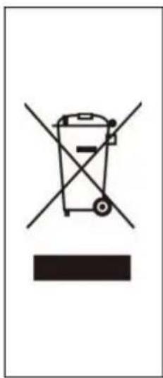
 | This marking indicates that this product should not be disposed with other household wastes throughout the E To prevent possible harm to the environment or hum health from uncontrolled waste disposal, recycle it responsibly to promote the sustainable reuse of mater resources. To return your used device, please use the and collection systems or contact the retailer where t product was purchased. They can take this product fi environmental safe recycling. |
VEVOR®
TOUGH TOOLS, HALF PRICE
Technical Support and E-Warranty Certificate www.vevor.com/support
VEVOR®
TOUGH TOOLS, HALF PRICE
natural_image
Line drawing of a stainless steel refrigerator with ventilation grilles and side-mounted door (no text or symbols)BESOIN D'AIDE? CONTACTEZ-NOUS!
DIMENSIONS/CONNEXION....6
NOTE......6
INFORMATIONS GÉNÉRALES....7
CONSTRUCTION DE L'UNITÉ PRINCIPALE....7
FABRICATION DE GLACE ET SES PIÈCES DE RÉSERVOIR D'EAU....8
PANNEAU DE COMMANDE....9
DESSIN EXPLOSIF....11
MODE D'EMPLOI ET ENTRETIEN....14
DÉBALLAGE DE VOTRE MACHINE À GLAÇONS....14 INVERSION DE LA
PORTE (en option)....15 EXIGENCES RELATIVES À L'EMPLACEMENT
D'INSTALLATION......17
EXIGENCES ÉLECTRIQUES ET CONNEXIONS....19
NETTOYER VOTRE MACHINE À GLACE AVANT LA PREMIÈRE UTILISATION....20
RACCORDEMENTS D'EAU POUR VOTRE MACHINE À GLACE....20
FONCTIONNEMENT DE VOTRE UNITÉ....22
FONCTIONNEMENT DU PROCESSUS DE FABRICATION DE GLACE....22
SCHÉMA DE CÂBLAGE....25
SONS NORMAUX....26
PRÉPARATION DE LA MACHINE À GLACE POUR UN STOCKAGE DE LONGUE DURÉE......26
NETTOYAGE ET ENTRETIEN....27
NETTOYAGE EXTÉRIEUR....28
NETTOYAGE INTÉRIEUR....28
NETTOYAGE DES PIECES DE FABRICATION DE GLACE....29
NETTOYAGE DU SYSTÈME D'ASSEMBLAGE DE FABRICATION DE GLACE À L'AIDE DE NU-CALGON
NETTOYANT POUR MACHINE À GLACE SANS NICKLE....31
SUGGESTION DE NETTOYAGE....33
DÉPANNAGE NORMAL....34
ÉLIMINATION CORRECTE DE CE PRODUIT....37
IMPORTANTES CONSIGNES DE SÉCURITÉ
1) DIMENSIONS/CONNEXIONS
text_image
380 [15.0] 850 [33.5] 820 [32.3] 159 [6.3] 516 [20.3] 426 [16.8] 47 [1.9] 550 [21.7]2) Notation
| MODÈLE | HBZB-36F |
| ALIMENTATION ÉLECTRIQUE TENSION | Monophasé, 220-240 V/50 Hz |
| CLASSE DE RÉCLAMATION | SN/N/ST/T |
| ÉLECTRIQUECLASSE DE PROTECTION | |
| COTE DE FABRICATION DE GLACE(Amplis) | 1,5 |
| COTE DE RÉCOLTE DE GLACE(Amplis) | 1.9 |
| CAPACITÉ DE FABRICATION DE GLACE(KG/24H) | 36 * |
| CHARGE DE RÉFRIGÉRANT | R290 2,29 onces / 65 g |
| POIDS NET (lb) | 53 |
| vésicant | C5H10 |
| DIMENSIONS DE L'UNITÉ (L x P)XH) (pouce) | 15x20,3x33,5 |
| STOCKAGE DE GLACE MAXIMUMCAPACITÉ (lbs) | 12 |
| ACCESSOIRES | PELLE, KITS D'INSTALLATION, MANCHE |
| CONNEXION | CORDON D'ALIMENTATION ---- 0,75 mm2ALIMENTATION EN EAU ----6,35 mm de diamètreTUYAU DE VIDANGE ---- Φ16mm SILFONSOUFFLET |
| CONDITIONS DE COURSE | TEMPÉRATURE AMBIANTE 10-43TEMPÉRATURE D'ALIMENTATION EN EAU 5-35PRESSION D'ALIMENTATION EN EAU 0,04-0,6 MPa |
REMARQUE * : TESTÉ À 21 DE TEMPÉRATURE AMBIANTE ET 10 D'EAU TEMPÉRATURE.
INFORMATIONS GÉNÉRALES
natural_image
Technical line drawing of a two-part electrical enclosure with internal components and mounting base (no text or symbols)text_image
Technical diagram of a mechanical assembly with labeled components A through J, showing cross-sectional views and structural details.text_image
Exploded view diagram of a refrigerator internal components with numbered labelstext_image
50 [2.0] 5 [0.2] 5 [0.2] 10.2 50 [2.0]natural_image
Simple line drawing of a coiled spring with a separate curved arrow pointing to it (no text or symbols)flowchart
graph LR
    A["STEP 1: Quick-connector and the water faucet"] --> B["STEP 2: Screw the quick-connector on the water faucet by the screw thread, and remove the clipper"]
    B --> C["STEP 4: Install back the clipper"]
    C --> D["Push inwards"]
STEP 3: Insert the water hose completely
FONCTIONNEMENT DE VOTRE UNITÉ
text_image
Little holes of water dividing pipe Water dividing pipe Evaporator Pull up first Then move out right towardtext_image
Ice-full detecting plate Water tanknatural_image
Technical line drawing of a mechanical component with grid structure and handle (no text or symbols)ÉLIMINATION CORRECTE DE CE PRODUIT
text_image
Warning symbol for a trash bin with crossed and uncorrected lines, indicating no waste or discharge.natural_image
Line drawing of a stainless steel refrigerator with ventilation grilles and side-mounted door (no text or symbols)text_image
Technical diagram of an internal device with labeled ports and internal compartments, including y-y coordinate axes.1.Tür
text_image
Technical diagram of a mechanical assembly with labeled components A through J, showing cross-sectional views and structural details.text_image
Exploded view diagram of a refrigerator internal components with numbered labelstext_image
50 [2.0] 5 [0,2] 5 [0,2] 100000000000000000000000000000000000000000000000000000000000000000000000 50 [2.0]natural_image
Simple line drawing of a coiled spring with a separate curved arrow pointing to it (no text or symbols)flowchart
graph LR
    A["STEP 1: Quick-connector and the water faucet"] --> B["STEP 2: Screw the quick-connector on the water faucet by the screw thread, and remove the clipper"]
    B --> C["STEP 4: Install back the clipper"]
    C --> D["Push inwards"]
STEP 3: Insert the water hose completely
BETRIEB IHRES GERÄTS
text_image
Little holes of water dividing pipe Water dividing pipe Evaporator Pull up first Then move out right towardtext_image
Ice-full detecting plate Water tanknatural_image
Technical line drawing of a mechanical component with grid structure and handle (no text or symbols)natural_image
Symbol of a trash bin crossed out by two diagonal lines, with no text or labels present.natural_image
Line drawing of a stainless steel refrigerator with ventilation grilles and side-mounted door (no text or symbols)DIMENSIONE/CONNESSIONE....6
VALUTAZIONE....6
PROCEDURA OPERATIVA E MANUTENZIONE....14
DISIMBALLAGGIO DELLA MACCHINA PER IL GHIACCIO....14
INVERSIONE DELLA PORTA (opzionale)....15 REQUISITI PER LA
text_image
Technical diagram of an electronic device showing internal components with labeled y-y coordinate axestext_image
Technical diagram of a mechanical assembly with labeled components A through J, showing cross-sectional views and structural details.text_image
Exploded view diagram of a refrigerator internal components with numbered labelstext_image
Piosura fisca Cupercia siccifer Camera Camera Maniglia Maniglia Piosura fisca shi-lisa in base a dri##e camera Piosura fisca shi-lisa in base a dri##e camera Piosura fisca shi-lisa in base a dri##e camera Piosura fisca shi-lisa in base a dri##e cameratext_image
50 [2.0] 5 [0.2] 5 [0.2] 10000000000000000000000000000000000000000000000000000000000000000000 50 [2.0]natural_image
Simple line drawing of a coiled spring with a separate curved arrow pointing to it (no text or symbols)flowchart
graph LR
    A["STEP 1: Quick-connector and the water faucet"] --> B["STEP 2: Screw the quick-connector on the water faucet by the screw thread, and remove the clipper"]
    B --> C["STEP 4: Install back the clipper"]
    C --> D["Push inwards"]
STEP 3: Insert the water hose completely
text_image
Little holes of water dividing pipe Water dividing pipe Evaporator Pull up first Then move out right towardtext_image
Ice-full detecting plate Water tanknatural_image
Technical line drawing of a mechanical component with grid structure and handle (no text or symbols)natural_image
Line drawing of a stainless steel refrigerator with ventilation grilles and side-mounted door (no text or symbols)www.vevor.com/support
DIAGRAMA DE CABLEADO....25
SONIDOS NORMALES....26
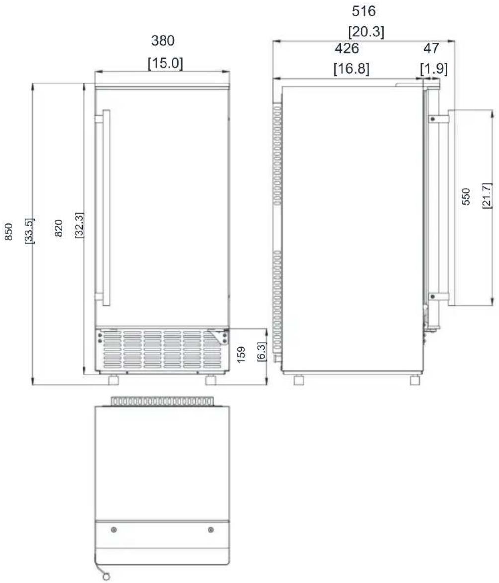
1) DIMENSIONES/CONEXIONES
text_image
380 [15.0] 850 [33.5] 820 [32.3] 159 [6.3] 516 [20.3] 426 47 [16.8] [1.9] 550 [21.7]2) Calificación
natural_image
Technical line drawing of a two-part electrical enclosure with internal components and mounting base (no text or symbols)text_image
Technical diagram of a mechanical assembly with labeled components A through J, showing cross-sectional views and structural details.text_image
Exploded view diagram of an electronic device with numbered components for identificationnatural_image
Diagram of a coiled spring with a separate curved arrow pointing to it (no text or symbols)flowchart
graph LR
    A["STEP 1: Quick-connector and the water faucet"] --> B["STEP 2: Screw the quick-connector on the water faucet by the screw thread, and remove the clipper"]
    B --> C["STEP 4: Install back the clipper"]
    C --> D["Push inwards"]
STEP 3: Insert the water hose completely
text_image
Little holes of water dividing pipe Water dividing pipe Evaporator Pull up first Then move out right towardtext_image
Ice-full detecting plate Water tanknatural_image
Technical line drawing of a mechanical component with grid structure and handle (no text or symbols)natural_image
Line drawing of a stainless steel refrigerator with ventilation grilles and side-mounted door (no text or symbols)POTRZEBUJESZ POMOCY? SKONTAKTUJ SIĘ Z NAMI!
WYMIARY/POŁĄCZENIE....6
OCENA....6
INFORMACJE OGÓLNE....7
BUDOWA JEDNOSTKI GŁÓWNEJ....7
PRODUKCJA LODU I CZĘŚCI ZBIORNIKA NA WODĘ....8
PANEL OPERACYJNY....9
RYSUNEK WYBUCHOWY....11
PROCEDURA OBSŁUGI I KONSERWACJI....14
ROZPAKOWYWANIE MASZYNY DO LODU....14 ODWRÓCENIE DRZWI
(opcjonalne)....15 WYMAGANIA DOTYCZĄCE MIEJSCA
INSTALACJI....17
WYMAGANIA I PODŁĄCZENIA ELEKTRYCZNE....19
CZYSZCZENIE KOSTKARKI DO LODU PRZED PIERWSZYM UŻYCIEM....20
PODŁĄCZENIA WODNE DO MASZYNY DO LODU....20
OBSŁUGA URZĄDZENIA....22
DZIAŁANIE PROCESU PRODUKCJI LODU....22
SCHEMAT OKABLOWANIA....25
DŻWIĘKI NORMALNE....26
PRZYGOTOWANIE MASZYNY DO LODU DO DŁUGIEGO PRZECHOWYWANIA....26
CZYSZCZENIE I KONSERWACJA....27
CZYSZCZENIE ZEWNETRZNE....28
text_image
380 [15,0] 850 [33,5] 820 [32,3] 159 [6,3] 516 [20,3] 426 [16,8] 47 [1,9] 550 [21,7]2)Ocena
| MODEL | HBZB-36F |
| ZASILANIEWOLTAŻ | 1 faza, 220-240 V/50 Hz |
| KLASA ROSZCZENIA | Nr seryjny/N/ST/T |
| ELEKTRYCZNYKLASA OCHRONY | I |
| OCENA PRODUKCJI LODU(Ampery) | 1,5 |
| OCENA ZBIORU LODU(Ampery) | 1.9 |
| WYDAJNOŚĆ PRODUKCJI LODU(KG/24h) | 36 * |
| ŁADUNEK CZYNNIKA CHŁODNICZEGO | R290 2,29 uncji / 65 g |
| MASA NETTO (funty) | 53 |
| wezykatoria | C5H10 |
| WYMIARY JEDNOSTKI (szer. x gł.)XH) (cal) | 15x20,3x33,5 |
| MAKSYMALNE PRZECHOWYWANIE LODUNOŚNOŚĆ (funty) | 12 |
| AKCESORIA | ŁOPATA, ZESTAWY INSTALACYJNE, UCHWYT |
| POŁĄCZENIE | PRZEWÓD ZASILAJĄCY---- 0,75 mm2DOPŁYW WODY----Średnica 6,35 mmRURA ODPŁYWOWA----SYLFON Φ16mmMiechy |
| WARUNKI BIEGOWE | TEMPERATURA POKOJOWA 10-43°CTEMP. DOPŁYWU WODY 5-35°CCIŚNIENIE WODY 0,04-0,6 MPa |
UWAGA *: TESTOWANO W TEMPERATURZE POKOJOWEJ 21°C I WODZIE 10°C TEMPERATURA.
INFORMACJE OGÓLNE
natural_image
Technical line drawing of a two-part electrical enclosure with internal components and mounting base (no text or symbols)text_image
Technical diagram of a mechanical assembly with labeled components A through J, showing cross-sectional views and structural details.text_image
Exploded view diagram of a refrigerator internal components with numbered labelsnatural_image
Pure mechanical component diagram showing a spiral coil and a separate curved component with an arrow indicating direction (no text or symbols)Najpierw usuń klips
KROK 2: W
Następnie przytnij
KROK 1: Usuń taśmę
flowchart
graph LR
    A["STEP 1: Quick-connector and the water faucet"] --> B["STEP 2: Screw the quick-connector on the water faucet by the screw thread, and remove the clipper"]
    B --> C["STEP 4: Install back the clipper"]
    C --> D["Push inwards"]
STEP 3: Insert the water hose completely
OBSŁUGA TWOJEGO URZĄDZENIA
text_image
Little holes of water dividing pipe Water dividing pipe Evaporator Pull up first Then move out right towardtext_image
Ice-full detecting plate Water tanknatural_image
Technical line drawing of a mechanical component with grid structure and handle (no text or symbols)natural_image
Symbol of a trash bin crossed out by two crossed lines, with a solid black rectangle below (no text or labels)natural_image
Line drawing of a stainless steel refrigerator with ventilation grilles and side-mounted door (no text or symbols)HULP NODIG? NEEM CONTACT MET ONS OP!
WERKING VAN HET IJSPRODUCTIEPROCES....22
BEDRADINGSSCHEMA....25
NORMALE GELUIDEN....26
HET IJSMACHINE VOORBEREIDEN VOOR LANGDURIGE BEWARING....26
REINIGING EN ONDERHOUD....27
EXTERIEURREINIGING....28
INTERIEURREINIGING....28
REINIGING VAN ONDERDELEN VOOR IJSMAKERS....29
REINIGING VAN HET IJSPRODUCTIESYSTEEM MET NU-CALGON
NIKKELVEILIGE IJSMACHINEREINIGER....31
REINIGINGSVOORSTEL....33
NORMALE PROBLEMEN OPLOSSEN....34
CORRECTE VERWIJDERING VAN DIT PRODUCT....37
BELANGRIJKE VEILIGHEIDSVOORSCHRIFTEN
text_image
Technical diagram of an electronic device showing internal components with labeled y-y coordinate axestext_image
Technical diagram of a mechanical assembly with labeled components A through J, showing cross-sectional views and structural details.text_image
Exploded view diagram of a refrigerator internal components with numbered labelstext_image
50 [2.0] 5 [0.2] 5 [0.2] 50 [2.0] [0.2]WAARSCHUWING: DEZE UNIT MOET GEAARD WORDEN.
natural_image
Simple line drawing of a coiled spring with a separate curved arrow pointing to it (no text or symbols)flowchart
graph LR
    A["STEP 1: Quick-connector and the water faucet"] --> B["STEP 2: Screw the quick-connector on the water faucet by the screw thread, and remove the clipper"]
    B --> C["STEP 4: Install back the clipper"]
    C --> D["Push inwards"]
STEP 3: Insert the water hose completely
BEDIENING VAN UW UNIT
text_image
Little holes of water dividing pipe Water dividing pipe Evaporator Pull up first Then move out right towardtext_image
Ice-full detecting plate Water tanknatural_image
Technical line drawing of a mechanical component with grid structure and handle (no text or symbols)natural_image
Symbol of a trash bin crossed out by two diagonal lines, with no text or labels present.garantiecertificaat www.vevor.com/support
VEVOR®
TOUGH TOOLS, HALF PRICE
www.vevor.com/support
AUTOMATISK ISMASKIN
MODELL: HBZB-36F
natural_image
Line drawing of a stainless steel refrigerator with ventilation grilles and side-mounted door (no text or symbols)BEHÖVER HJÄLP? KONTAKTA OSS!
DIMENSION/ ANSLUTNING....6
GRADERING....6
ALLMÄN INFORMATION....7
KONSTRUKTION AV HUVUDENHET....7
IS-TILLVERKNING OCH DESS VATTENTANKDELAR....8
DRIFTPANELEN....9
EXPLOSIV RITNING....11
KLEDNINGSDIAGRAM....25
NORMALA LJUD....26
FÖRBEREDA ISMASKINEN FÖR LÅNGFÖRVARING....26
RENGÖRING OCH UNDERHÅLL....27
EXTERIÖR RENGÖRING....28
INRE STÄDNING....28
RENGÖRING AV ISDELAR 29
RENGÖRING GENOM ATT ANVÄNDA NU-CALGON
NICKLE SAFE ICE-MASKINE CLEANER....31
RENGÖRINGSFÖRSLAG....33
NORMAL FELSÖKNING....34
KORREKT AVFALLSHANTERING AV DENNA PRODUKT....37
VIKTIG SÄKERHET
text_image
Technical diagram of an electronic device showing internal components with labeled y-y coordinate axestext_image
Technical diagram of a mechanical assembly with labeled components A through J, showing cross-sectional views and structural details.text_image
Exploded view diagram of a refrigerator with numbered components for identificationnatural_image
Simple line drawing of a coiled spring with a separate curved arrow pointing to it (no text or symbols)flowchart
graph LR
    A["STEP 1: Quick-connector and the water faucet"] --> B["STEP 2: Screw the quick-connector on the water faucet by the screw thread, and remove the clipper"]
    B --> C["STEP 4: Install back the clipper"]
    C --> D["Push inwards"]
STEP 3: Insert the water hose completely