HL15000 - Trailer hitch Vevor - Free user manual and instructions
Find the device manual for free HL15000 Vevor in PDF.

| Brand | Vevor |
| Model | HL15000 |
| Product Type | Weight Distribution Hitch |
| Gross Trailer Weight Capacity | 15,000 lb |
| Tongue Weight Capacity | 1,500 lb |
| Hitch Ball Diameter | 2-5/16" |
| Adjustable Shank Length | 2" |
| Material | Heavy-Duty Steel |
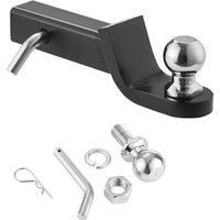
| Included Components | Hitch head, spring bars (2), spring bar brackets (2), adjustable shank, bolts, hitch pin, hitch ball, nuts, washers |
| Usage | Towing heavy trailers with weight distribution |
| Installation | Requires assembly and adjustment, see detailed manual |
| Maintenance | Regular lubrication of spring bars and sockets, cleaning, anti-rust paint |
| Safety | Do not exceed capacities, check all connections before towing |
| Warranty | Technical support and electronic warranty certificate at www.vevor.com/support |
Frequently Asked Questions - HL15000 Vevor
User questions about HL15000 Vevor
0 question about this device. Answer the ones you know or ask your own.
Ask a new question about this device
Download the instructions for your Trailer hitch in PDF format for free! Find your manual HL15000 - Vevor and take your electronic device back in hand. On this page are published all the documents necessary for the use of your device. HL15000 by Vevor.
USER MANUAL HL15000 Vevor
Technical Support and E-Warranty Certificate www.vevor.com/support
WEIGHT DISTRIBUTION HITCH
MODEL: HL15000
We continue to be committed to provide you tools with competitive price. "Save Half", "Half Price" or any other similar expressions used by us only represent of savings you might benefit from buying certain tools with us compared top brands and doses not necessarily mean to cover all categories of tools offered are kindly reminded to verify carefully when you are placing an order with us actually saving half in comparison with the top major brands.
VEVOR®
TOUGH TOOLS, HALF PRICE
WEIGHT DISTRIBUTION HITCH
MODEL: HL15000
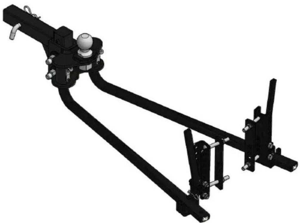
natural_image
Mechanical linkage assembly diagram with articulated and linear components (no text or symbols)NEED HELP? CONTACT US!
Haveproductquestions?Needtechnicalsupport?Pleasefeelfreeto contactus: Technical Support and E-Warranty Certificate www.vevor.com/support
Thisistheoriginalinstruction, pleasereadallmanualinstructions carefullybeforeoperating.VEVORreservesaclearinterpretationofour usermanual.Theappearanceoftheproductshallbesubjecttothe productyoureceived.Pleaseforgiveusthatwewon'tinformyouagainif thereareanytechnologyorsoftwareupdatesonourproduct.

Warning-To reduce the risk of injury, user must read instructions manual carefully.
WARNING:
-
Read and understand all instructions. Failure to follow all instruction listed below may result in serious injury.
-
Various dangers may occur if the hand lever grease gun is improved, handled during installation, commissioning and daily operation.
-
Risk of injury and damage to material property because of improper handling. Hold the manual at the disposal of the operating staff at the usage site of the unit. Country-specific safety measures and accident prevention regulations must be observed.
-
Persons are qualified if they are, due to their training, experience, instruction and knowledge of the relevant standards, able to assess assigned tasks and to identify potentially hazardous situations.
-
Never exceed the vehicle manufacturer's recommended towing capacity.
-
The loaded ball height should never be greater than the uncoupled height. Front wheel overload and loss of rear wheel traction can lead unstable handling. It can reduce braking ability and create a tendency jackknife when turning and braking at the same time.
-
If the loaded trailer ball height is greater than the uncoupled height, reduce take-up on the spring bar, remeasure and adjust until the proper height is obtained.
-
This product is not a toy, and the dump truck mesh tarp cannot as toys for children to play with.
CAUTION:
-
Defective accessories should be replaced immediately. Defective accessories can lead to personal injury and material damage.
-
During their period of use, accessories must be checked for wear, and other damage.
SAVE THESE INSTRUCTIONS
MODEL AND PARAMETERS
| Model: | HL15000 |
| Gross Trailer Weight: | 15000 lbs |
| Tongue Weight: | 1500 lbs |
| Hitch Ball: | 2-5/16" |
| Adjustable Shank: | 2" |
COMPONENTS
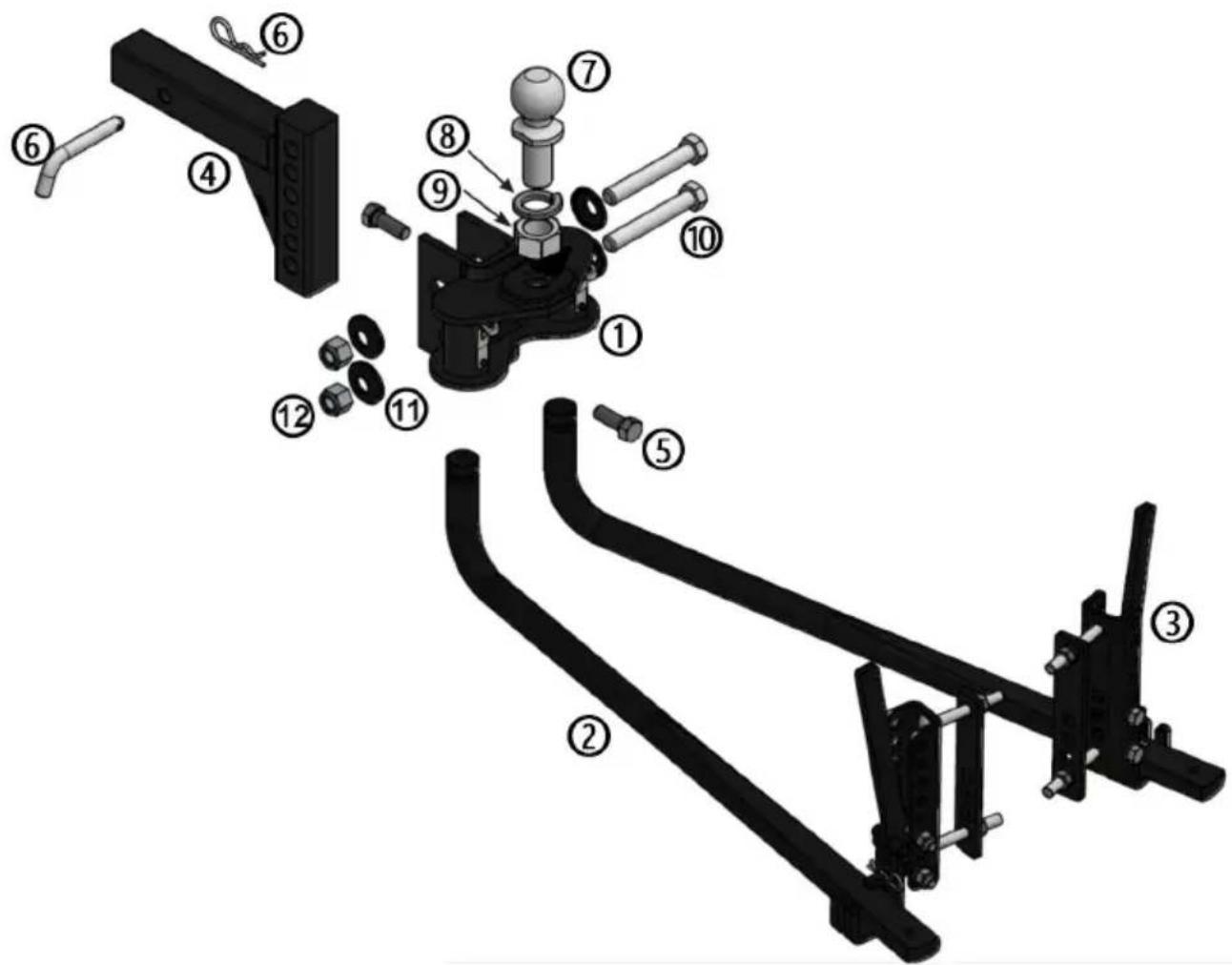
| Parts List | ||
| Item | Quantity | Description |
| 1 | 1 | Hitch head |
| 2 | 2 | Spring bar |
| 3 | 2 | Spring bar support bracket assembly |
| 4 | 1 | Adjustable shank |
| 5 | 2 | Hex bolt, 5/8"-11 x 1-3/4" |
| 6 | 1 | Hitch pin & clip |
| 7 | 1 | Hitch ball, 2-5/16" |
| 8 | 1 | Lock washer,1-1/4" |
| 9 | 1 | Hex nut, 1-1/4"-12 |
| 10 | 2 | Hex bolt, 3/4"-10x5" |
| 11 | 4 | Serrated conical washer 3/4" |
| 12 | 2 | Nylock nut,3/4"-10 |
ASSEMBLY & INSTALLATION
Step 1:
Insert adjustable shank bar(#4) into receiver tube on tow vehicle and secure with hitch pin&clip(#6).
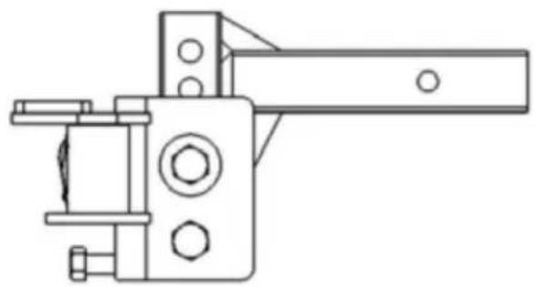
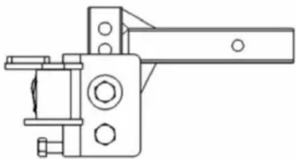
NOTE: To obtain proper ball height on high ground clearance
vehicles, shank may be inverted as shown below. If shank is used in the inverted position, check for adequate ground clearance.
UP POSITION
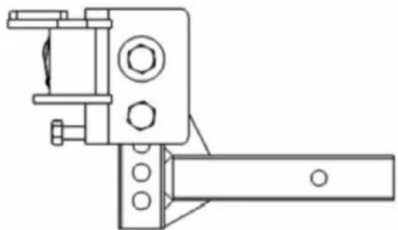
natural_image
Technical line drawing of a mechanical clamp or bracket assembly (no text or symbols)DOWN POSITION
natural_image
Technical line drawing of a mechanical clamp or bracket device (no text or symbols)Step 2:
Torque ball to 360ft-lbs.Secure the ball to the head assembly(#1) us lock washer(#8) and nut(#9).
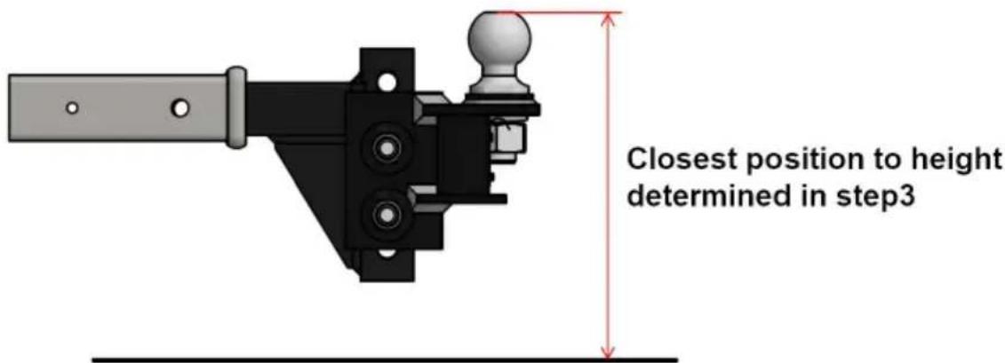
Step 3:
Position head assembly on shank. Slide head up or down to the r bolt hole alignment position which corresponds with the target ball h determined earlier. Mark the position on the shank.
Step 4:
Install the head on the shank at marked position. Insert the 3/4"-10 hex bolt(#10) through the 3/4" conical washer(#11) and then through lower hole in the head channel. Rotate the head forward as far as go. The ball should be vertical or tilted slightly back. If it is not, adjust screws(#5). Install the remaining 3/4"-10 x 5" hex bolt(#10) with 3/4" conical washer(#11) through the upper slotted hole. Install a second 3/4" conical washer(#11) on both bolts. Start 3/4"-10(#12) nylock nuts and finger tighten only.
Step 5:
Tighten top 3/4"-10 x 5 hex bolt(#10) just enough to hold head tig against the pin in the head channel. This bolt will be tightened late
Step 6: Install spring bars
Apply a heavy grease on the round end of each spring bar and p up into the head socket until you hear a click, as shown below. T indicate that the spring bar is locked into place. To release spring up slightly on spring bar and gently pull out on the retaining pin in hitch head. The spring bar will be dropped free of the hitch head.
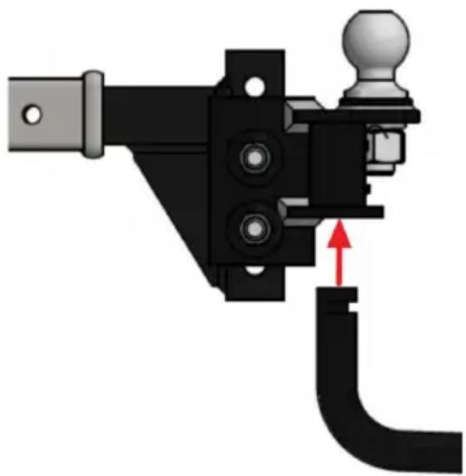
natural_image
Mechanical component diagram showing a lever mechanism with a red arrow indicating motion direction (no text or symbols present)Step 7: Attaching the trailer to the ball
Using the trailer tongue jack, lower the coupler onto the trailer ball close coupler latch. Do not retract jack fully at this time. Allow the
support some of the tongue weight.
Raise the front of the trailer and back of the tow vehicle approxim with tongue jack or until the rear bumper is back to the initial mea height. This will allow easier installation of the spring bars onto the support brackets.
Step 8:Installing the spring bar support brackets
Mark the position of the support brackets (#3) by making a center the trailer A-frame a minimum of 4" in from the end of the spring (#2).
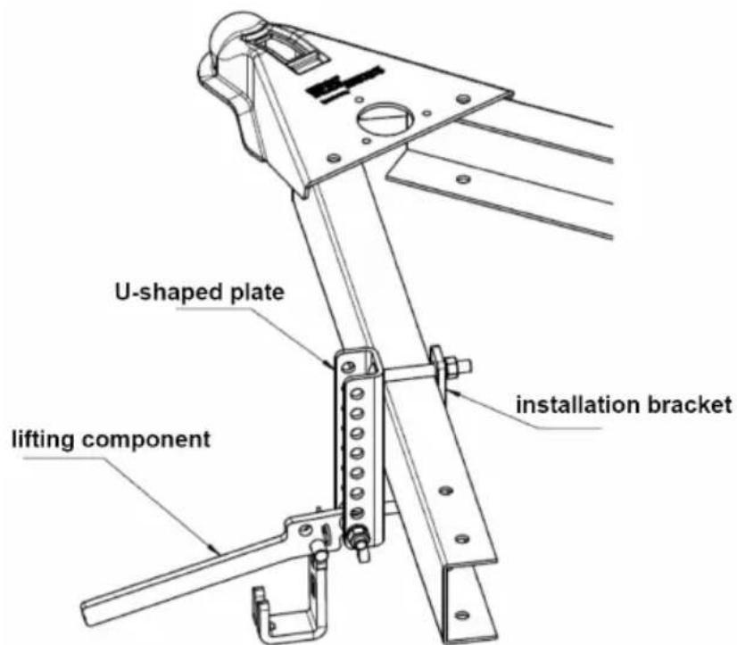
Step 9:
Assemble and fasten the U-shaped installation plate and bracket on the tracker A-frame using two 1/2-13UNC-4 "carriage bolts, two 1/2-13UNC hex nuts, and spring washers. Then, assemble the lifting component onto the mounting bracket and secure it using one 1/2-13UNC-3" hex head bolt, 1/2-13UNC nut, and spring washer. All must have a torque of 45-55ft-lbs.
Step 10: Raise the spring bars
Place the end of the spring bar into the groove of the lifting comp
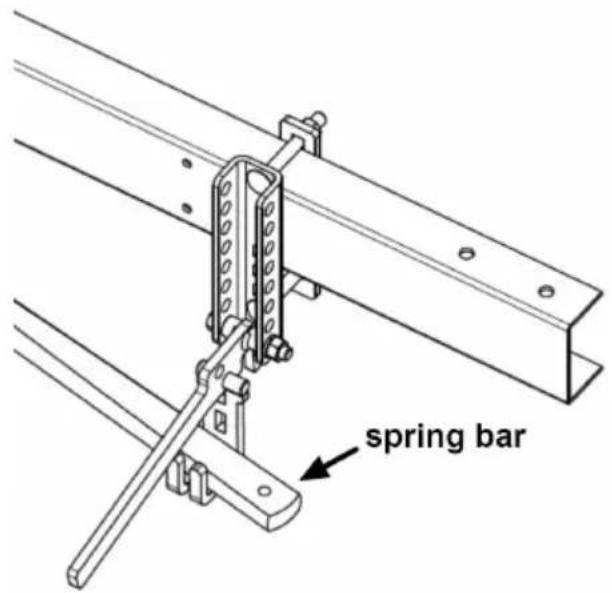
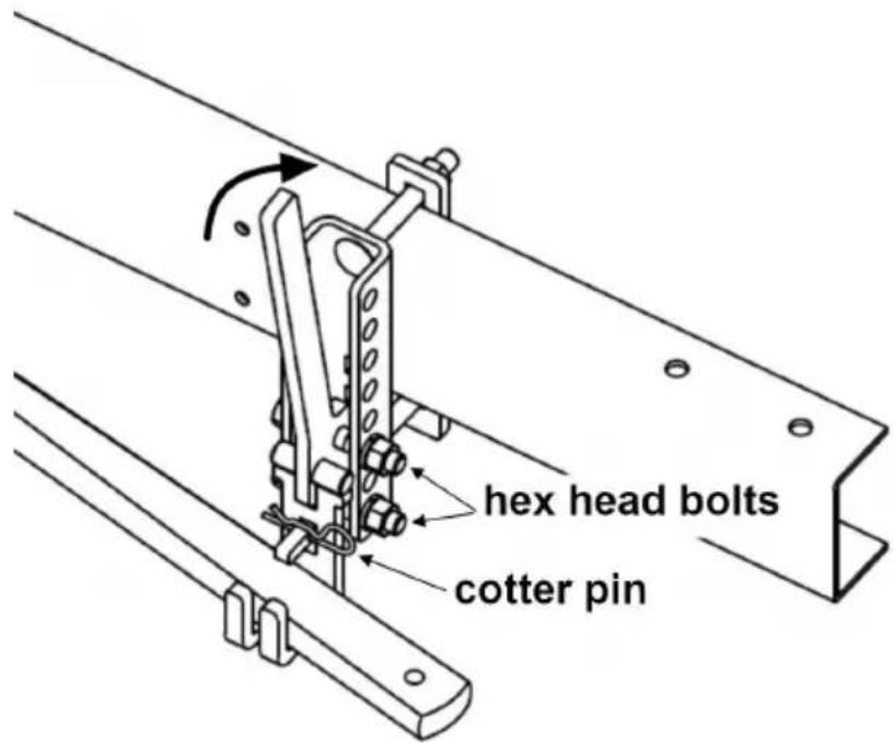
Step 11:
Lift the lifting component and secure it to the U-shaped groove plate using two 1/2"-13UNC-3 " hex head bolts, two 1/2"-13UNC nuts, an spring washers each. All nuts must have a torque of 45-55ft lbs. The secure the spring bar by installing the cotter pin.
Step 12:
Check the vehicle height and adjust the angle of the head using the screws (#5) as required until desired loading is reached. With the s
bars secured, lower the jack to apply load to the hitch. The vehicle should settle evenly. Remeasure the front and rear bumper reference points. If the front has settled much more than the rear, adjust the screws until the vehicle and trailer are level. The spring bars should nearly horizontal when correct height is achieved.
Step 13:
Tighten all 3/4" bolts and lock nuts to 200 ft-lbs. Tighten the set is (#5) to 50 ft-lbs. Failure to tighten the hardware may result in fast loss or failure.
Before You Tow:
Check all connections listed below prior to towing:
- Hitch pin & clip (securing shank to receiver)
- Head to shank fasteners
- Trailer ball nut
- Coupler latch
- Spring bar support brackets
- Safety chains
- Lights and turn signals
- Braking system (including breakaway switch)
MAINTENANCE
-
Keep the socket-mounted ends of the spring bars and the lock pin the head assembly free from dirt and well lubricated. Excessive wear area may indicate an overload or inadequate lubrication.
-
Keep the head assembly exterior clean. Do not allow dirt or stone lodge between the spring bars and the head.
- Keep hitch parts painted to prevent rust and maintain good appeal. Do not paint over labels.
- Keep lift brackets clean and lubricated to ensure ease of operation.
MADE IN CHINA
VEVOR®
TOUGH TOOLS, HALF PRICE
Technical Support and E-Warranty Certificate www.vevor.com/support
VEVOR®
TOUGH TOOLS, HALF PRICE
natural_image
Mechanical linkage assembly diagram with articulated joints and mounting brackets (no text or symbols)BESOIN D'AIDE? CONTACTEZ-NOUS!
natural_image
Technical line drawing of a mechanical clamp or bracket assembly (no text or symbols)DOWN POSITION

natural_image
Technical line drawing of a mechanical clamp or bracket component (no text or symbols)Étape 2 :
Étape 4 :
natural_image
Mechanical component diagram showing a lever mechanism with a red arrow indicating motion direction (no text or symbols present)Étape 11 :
Étape 12 :
natural_image
Mechanical linkage assembly diagram with articulated joints and mounting brackets (no text or symbols)natural_image
Technical line drawing of a mechanical clamp or bracket assembly (no text or symbols)DOWN POSITION

natural_image
Technical line drawing of a mechanical clamp or bracket component (no text or symbols)Schritt 2:
Schritt 4:
natural_image
Mechanical component diagram showing a lever mechanism with a red arrow indicating motion direction (no text or symbols present)Schritt
Schritt
natural_image
Mechanical linkage assembly diagram with articulated arms and mounting brackets (no text or symbols)natural_image
Technical line drawing of a mechanical clamp or bracket assembly (no text or symbols)DOWN POSITION

natural_image
Technical line drawing of a mechanical clamp or bracket component (no text or symbols)Fase 2:
Fase 4:
natural_image
Mechanical assembly diagram showing a lever mechanism with a red arrow indicating motion direction (no text or symbols present)Fase 10: sollevare le barre a molla
Fase 11:
Fase 12:
natural_image
Mechanical linkage assembly diagram with articulated joints and mounting brackets (no text or symbols)natural_image
Technical line drawing of a mechanical clamp or bracket assembly (no text or symbols)DOWN POSITION

natural_image
Technical line drawing of a mechanical clamp or bracket component (no text or symbols)Paso 2:
Paso 4:
natural_image
Mechanical component diagram showing a lever mechanism with a red arrow indicating motion direction (no text or symbols present)Paso 11:
Paso 12:
natural_image
Mechanical linkage assembly diagram with articulated joints and mounting brackets (no text or symbols)POTRZEBUJESZ POMOCY? SKONTAKTUJ SIĘ Z NAMI!
natural_image
Technical line drawing of a mechanical clamp or bracket assembly (no text or symbols)DOWN POSITION

natural_image
Technical line drawing of a mechanical clamp or bracket component (no text or symbols)Krok 2:
Krok 4:
natural_image
Mechanical assembly diagram showing a lever mechanism with a red arrow indicating motion direction (no text or symbols present)Krok 11:
Krok 12:
Machine Translated by Google
natural_image
Mechanical linkage assembly diagram with articulated joints and mounting brackets (no text or symbols)HULP NODIG? NEEM CONTACT MET ONS OP!
natural_image
Technical line drawing of a mechanical clamp or bracket assembly (no text or symbols)DOWN POSITION

natural_image
Technical line drawing of a mechanical clamp or bracket component (no text or symbols)Stap 2:
Stap 4:
natural_image
Mechanical assembly diagram showing a lever mechanism with a red arrow indicating motion direction (no text or symbols present)Stap 11:
Stap 12:
natural_image
Mechanical linkage assembly diagram with articulated joints and mounting brackets (no text or symbols)BEHÖVER HJÄLP? KONTAKTA OSS!
natural_image
Technical line drawing of a mechanical clamp or bracket assembly (no text or symbols)DOWN POSITION