USER MANUAL DI850 SCHEPPACH
natural_image
Exterior view of a modern electric drill with a black handle and control panel (no visible text or symbols)
DI850
natural_image
Mechanical component with labeled parts and dimension arrows (no text or symbols beyond numbers)
4
Günzburger Straße 69
D-89335 Ichenhausen
VEREHRTER KUNDE,
Explanation of the symbols on the equipment
 | GB | Warning! Danger to life, risk of injury or damage to the tool are possible by ignoring!. |
 | GB | Caution - Read the operating instructions to reduce the risk of inquiry |
 | GB | Wear safety goggles! |
 | GB | Wear a breathing mask! |
 | GB | Wear ear-muffs! |
 | GB | Protection class II |
Introduction
MANUFACTURER:
Günzburger Straße 69
D-89335 Ichenhausen
DEAR CUSTOMER,
We hope your new tool brings you much enjoyment and success.
NOTE:
According to the applicable product liability laws, the manufacturer of the device does not assume liability for damages to the product or damages caused by the product that occurs due to:
- Improper handling,
• Non-compliance of the operating instructions,
• Repairs by third parties, not by authorized service technicians,
• Installation and replacement of non-original spare parts,
• Application other than specified,
- A breakdown of the electrical system that occurs due to the non-compliance of the electric regulations and VDE regulations 0100, DIN 57113 / VDE0113.
WE RECOMMEND:
Read through the complete text in the operating instructions before installing and commissioning the device.
The operating instructions are intended to help the user to become familiar with the machine and take advantage of its application possibilities in accordance with the recommendations.
The operating instructions contain important information on how to operate the machine safely, professionally and economically, how to avoid danger, costly repairs, reduce downtimes and how to increase reliability and service life of the machine.
In addition to the safety regulations in the operating instructions, you have to meet the applicable regulations that apply for the operation of the machine in your country.
Keep the operating instructions package with the machine at all times and store it in a plastic cover to protect it from dirt and moisture. Read the instruction manual each time before operating the machine and carefully follow its information. The machine can only be operated by persons who were instructed concerning the operation of the machine and who are informed about the associated dangers. The minimum age requirement must be complied with.
In addition to the safety requirements in these operating instructions and your country's applicable regulations, you should observe the generally recognized technical rules concerning the operation of woodworking machines.
Device description (Fig. 1)
1 Drilling/hammer-drilling selector switch
2 Gear selector switch
3 Depth stop
4 Depth stop release
5 Quick-release chuck
5a Front sleeve
5b Rear sleeve
6 Additional handle lock
7 Additional handle
8 Rotational direction switch
9 Speed adjustment dial
10 On/off switch
11 Handle
12 Locking knob for continuous running
Unpacking
- Open the packaging and remove the device carefully.
- Remove the packaging material as well as the packaging and transport bracing (if available).
- Check that the delivery is complete.
- Check the device and accessory parts for transport damage.
- If possible, store the packaging until the warranty period has expired.
ATTENTION
The device and packaging materials are not toys! Children must not be allowed to play with plastic bags, film and small parts! There is a risk of swallowing and suffocation!
Intended use
The device is intended:
- for impact drilling in concrete, masonry or rocks,
• for drilling in wood, metal or plastic,
- for screwing in and loosening screws.
Any other use that is not explicitly approved in these instructions may result in damage to the equipment and represent a serious danger to the user.
For security reasons, the device is not intended for children and young people under the age of 16.
Young people aged 16 and over may only use the device under adult supervision. The device is not designed for commercial use.
The manufacturer cannot be held liable for damage when the appliance is not used in conformity with its intended purpose or due to incorrect operation.
Read all safety warnings and all instructions. Failure to follow the warnings and instructions may result in electric shock, fire and/or serious injury.
Save all warnings and instructions for future reference.
The term „power tool“ in the warnings refers to your mains-operated (corded) power tool or battery operated (cordless) power tool.
1. Work area safety
a) Keep work area clean and well lit. Cluttered or dark areas invite accidents.
b) Do not operate power tools in explosive atmospheres, such as in the presence of flammable liquids, gases or dust. Power tools create sparks which may ignite the dust or fumes.
c) Keep children and bystanders away while operating a power tool. Distractions can cause you to lose control.
2. Electrical safety
a) Power tool plugs must match the outlet. Never modify the plug in any way. Do not use any adapter plugs with earthed (grounded) power tools. Unmodified plugs and matching outlets will reduce risk of electric shock.
b) Avoid body contact with earthed or grounded surfaces, such as pipes, radiators, ranges and refrigerators. There is an increased risk of electric shock if your body is earthed or grounded.
c) Do not expose power tools to rain or wet conditions. Water entering a power tool will increase the risk of electric shock.
d) Do not abuse the cord. Never use the cord for carrying, pulling or unplugging the power tool. Keep cord away from heat, oil, sharp edges or moving parts. Damaged or entangled cords increase the risk of electric shock.
e) When operating a power tool outdoors, only use an extension cable suitable for outdoor use. Use of a cord suitable for outdoor use reduces the risk of electric shock.
f) If operating a power tool in a damp location is unavoidable, use a residual current device (RCD) protected supply. Use of an RCD reduces the risk of electric shock.
3. Personal safety
a) Stay alert, watch what you are doing and use common sense when operating a power tool. Do not use a power tool while you are tired or under the influence of drugs, alcohol or medication. A moment of inattention while operating power tools may result in serious personal injury.
b) Use personal protective equipment. Always wear eye protection. Protective equipment such as dust mask, non-skid safety shoes, hard hat, or hearing protection used for appropriate conditions will reduce personal injuries.
c) Prevent unintentional starting. Ensure the switch is in the off-position before connecting to power source and/or battery pack, picking up or carrying the tool. Carrying power tools with your finger on the switch or energising power tools that have the switch on invites accidents.
d) Remove any adjusting key or wrench before turning the power tool on. A wrench or a key left attached to a rotating part of the power tool may result in personal injury.
e) Do not overreach. Keep proper footing and balance at all times. This enables better control of the power tool in unexpected situations.
f) Dress properly. Do not wear loose clothing or jewellery. Keep your hair, clothing and gloves away from moving parts. Loose clothes, jewellery or long hair can be caught in moving parts.
g) If devices are provided for the connection of dust extraction and collection facilities, ensure these are connected and properly used. Use of dust collection can reduce dust-related hazards.
a) Do not force the power tool. Use the correct power tool for your application. The correct power tool will do the job better and safer at the rate for which it was designed.
b) Do not use the power tool if the switch does not turn it on and off. Any power tool that cannot be controlled with the switch is dangerous and must be repaired.
c) Disconnect the plug from the power source and/or the battery pack from the power tool before making any adjustments, changing accessories, or storing power tools. Such preventive safety measures reduce the risk of starting the power tool accidentally.
d) Store idle power tools out of the reach of children and do not allow persons unfamiliar with the power tool or these instructions to operate the power tool. Power tools are dangerous in the hands of untrained users.
e) Maintain power tools. Check for misalignment or binding of moving parts, breakage of parts and any other condition that may affect the power tools operation. If damaged, have the power tool repaired before use. Many accidents are caused by poorly maintained power tools.
f) Keep cutting tools sharp and clean. Properly maintained cutting tools with sharp cutting edges are less likely to bind and are easier to control.
g) Use the power tool, accessories and tool bits, etc. in accordance with these instructions, taking into account the working conditions and the work to be performed. Use of the power tool for operations different from those intended could result in a hazardous situation.
5. Service
a) Have your power tool serviced by a qualified repair person using only identical replacement parts. This will ensure that the safety of the power tool is maintained.
b) Always arrange for the replacement of the plug or the power cord to be carried out by the manufacturer of the appliance or by his approved customer services. This will ensure that the safety of the power tool is maintained.
a) Wear ear protection during impact drilling. The exposure to noise can cause hearing loss.
b) Use the additional handles delivered with the device. The loss of control can result in injuries.
c) Hold the device by the insulated gripping surfaces when performing work in which the cutting tool may come into contact with hidden wiring or its own cord. Contact with a live wire can also cause a charge in metal parts of the device and result in an electric shock.
d) Use suitable detectors in order to find hidden supply lines or ask the local utility company. Contact with electrical cables can lead to electric shock and fire, contact with a gas pipe can result in an explosion. Damage to a water pipe can lead to property damaged and electric shock.
e) Keep hands away from rotating parts. Wait until the power tool has stopped before placing it down. Risk of injury!
f) Avoid contact with the tool insert or the component part immediately after processing. The parts may be hot and cause burn injuries.
g) Immediately switch off the power tool if the tool insert is blocked due to overloading or tilting of the component part. The loss of control can result in injuries.
h) Secure moving component part with clamping devices. A hand held tool can slip and endanger your safety.
i) The device must only be connected to a mains socket via a residual-current circuit breaker (RCD) with a rated leakage current of not more than 30 mA.
Residual risks
Even if you use this electric power tool in accordance with instructions, certain residual risks cannot be rules out. The following hazards may arise in connection with the equipment's construction and layout:
- Lung damage if no suitable protective dust mask is used.
- Damage to hearing if no suitable ear protection is used.
- Health damage caused by hand-arm vibrations if the equipment is used over a prolonged period or is not properly guided and maintained.
Technical Data
| Rated input voltage 220-230 V~ / 50 Hz |
| Idling speed n_0 | 0-1000 min ^-1 0-2800 min ^-1 |
| Power input (power con-sumption) P | 1050W |
| Blow count | 0-16000 min ^-1 0-44800 min ^-1 |
| Max. Drill size | 13 mm |
| Max. drill diameterin wood | 30 mm |
| in concrete | 20 mm |
| in steel | 13 mm |
| Protection class | II |
| Protection category | IPX0 |
| Weight | 3,2 kg |
Noise and vibration values
The total noise values determined in accordance with EN 60745.
| sound pressure level L_pA | 95 dB(A) |
| uncertainty K_pA | 3 dB |
| sound power level L_WA | 106 dB(A) |
| uncertainty K_WA | 3 dB |
Wear hearing protection.
The effects of noise can cause a loss of hearing Total vibration values (vector sum - three directions) determined in accordance with EN 60745.
Drilling in metal: 7,31 m/s ^2 , K=1,5 m/s ^2
Impact drilling in concrete: 16,93 m/s ^2 , K= 1,5 m/s ^2
The specified vibration value was established in accordance with a standardized testing method. It may change according to how the electric equipment is used and may exceed the specified value in exceptional circumstances.
The specified vibration value can be used to compare the equipment with other electric power tools.
The specified vibration value can be used for initial assessment of a harmful effect.
Mounting
Pull out the power plug before carrying out any work on the equipment. There is a risk of electrocution or of injury from moving parts.
Mounting/pivoting the additional handle (Fig. 2/3)
Do not use the device without the additional handle. It provides additional hold and reduces the risk of injury.
- Release the lock for the additional handle (6).
- Insert the additional handle (7) over the keyless chuck (5) on to the device.
- Pivot the additional handle (7) into the desired position.
- Retighten the lock for the additional handle (6).
The additional handle is equally suited for right and left-handed person.
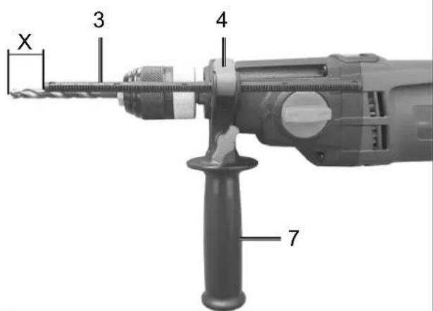
Mount/set depth stop (Fig. 4)
The boreholes can be precisely drilled to an exact drilling depth x using the depth stop.
- Press the depth stop release (4).
- Use the depth stop (4) in the additional handle (7). Make sure that the flute of the depth stop (4) engages the flute of the additional handle (7).
- Place the tip of the depth stop (3) to the desired drilling depth x behind the tip of the drill.
- Let go of the depth stop release (4). The depth stop (3) is now locked.
- Drill the hole until the depth stop (3) comes in contact with the component part.
- Open the keyless chuck (5) wide (RELEASE) so that the tool can be inserted. To do so, firmly hold the rear sleeve (5b) of the keyless chuck (5) and turn the front sleeve (5a) in the anti-clockwise direction.
- Insert the tool as far as possible into the keyless chuck (5).
- Close the keyless chuck (5) (GRIP) in order to clamp the tool. To do so, firmly hold the rear sleeve (5b) of the keyless chuck (5) and turn the front sleeve (5a) in the clockwise direction.
- To remove the tool again, rotate the keyless chuck (5) and pull out the tool.
Always use a universal bit holder use using a screw-driver bits.
Operation
Do not use the device without the additional handle. It provides additional hold and reduces the risk of injury.
Observe noise control and local regulations.
Switching on and off (Fig. 1)
- Connect the machine to the power supply. Make sure that the net voltage matches the voltage rating indicated on the device's type plate. Switching on: Press the on/off switch (10).
- By using the on/off switch (10)) you can progressively control the speed.
Gentle pressure: low speed
Increase pressure: higher speed.
- Continuous operation: Press the lock button (12). The on/off switch (10)) is locked.
- Switching off: Release the on/off switch (10). For continuous operation, briefly press the on/off switch (10).
Defining the speed range (Fig. 1)
The gear selector switch (2) allows you to work within a specific speed range.
Switch position stage 1
Speed range: High torque, low speed
Switch position stage 2
Speed range: Low torque, high speed
Preselecting the speed (Fig. 1)
- The speed adjustment dial (9) allows you to define the maximum speed.
- Set the speed adjustment dial (9) to the desired position.
- If the on/off switch (10) is fully depressed, the motor will still only turn as fast as the setting on the speed adjustment dial (9).
- This setting can also be adjusted during operation.
Set the direction of rotation (Fig. 1)
The device's direction of rotation can be changed with the rotational direction switch.
- Wait for the device to shut-down.
- Push the rotational direction speed (8) into the desired position:
Clockwise rotation: to drill and screw in screws.
Anticlockwise rotation: to loosen screws.
Changeover drilling/impact drilling (Fig. 1)
- Wait for the device to shut-down.
- Set the changeover switch (1) to the "Drill" symbol.
- Impact drilling: Set the changeover switch (1) to the "Impact drill" symbol.
Practical tips
• Always use the proper tool.
- Immediately switch of the device, if the tool should get jammed. Change the rotation direction to anticlockwise rotation and the carefully unscrew the jammed tool.
- Do not use any blunt or damaged tools or accessories.
Electrical connection
The electrical motor installed is connected and ready for operation. The connection complies with the applicable VDE and DIN provisions.
The customer's mains connection as well as the extension cable used must also comply with these regulations.
In the event of an overloading the motor will switch itself off. After a cool-down period (time varies) the motor can be switched back on again.
Damaged electrical connection cable
The insulation on electrical connection cables is often damaged.
This may have the following causes:
• Passage points, where connection cables are passed through windows or doors.
- Kinks where the connection cable has been improperly fastened or routed.
- Places where the connection cables have been cut due to being driven over.
- Insulation damage due to being ripped out of the wall outlet.
- Cracks due to the insulation ageing.
Such damaged electrical connection cables must not be used and are life-threatening due to the insulation damage.
Check the electrical connection cables for damage regularly. Make sure that the connection cable does not hang on the power network during the inspection. Electrical connection cables must comply with the applicable VDE and DIN provisions. Only use connection cables with the marking „H05VV-F“.
The printing of the type designation on the connection cable is mandatory.
AC motor
- The mains voltage must be 230 V\~
- Extension cables up to 25 m long must have a cross-section of 1.5 mm ^2 .
Connections and repairs of electrical equipment may only be carried out by an electrician.
Please provide the following information in the event of any enquiries:
• Type of current for the motor
• Machine data - type plate
• Machine data - type plate
Cleaning and Servicing
Pull the mains plug before any adjustments, maintenance or repair.
△ Have any work on the device that is not described in this instruction guide performed by a professional. Only use original parts. Allow the device to cool off before any maintenance or cleaning is undertaken. There is a risk of burning!
Always check the device before using it for obvious defects such as loose, worn or damaged parts, correct the positioning of screws or other parts. Exchange the damaged parts.
Cleaning
Do not use any cleaning agents or solvents. Chemical substances can etch the plastic parts of the device. Never clean the device under running water.
• Thoroughly clean the device after every use.
- Clean the ventilation openings and the surface of the device with a soft brush or cloth.
- Remove chips, dust and dirt with a vacuum cleaner if necessary.
- Lubricate moving parts regularly.
Please note that the following parts of this product are subject to normal or natural wear and that the following parts are therefore also required for use as consumables.
Wear parts*: Carbon brushes, v-belt, batteries, drill bit
* Not necessarily included in the scope of delivery!
Storage
Store the device and its accessories in a dark, dry and frost-proof place that is inaccessible to children. The optimum storage temperature is between 5 and 30°C.
Store the electrical tool in its original packaging. Cover the electrical tool in order to protect it from dust and moisture.
Store the operating manual with the electrical tool.
Disposal and recycling
The equipment is supplied in packaging to prevent it from being damaged in transit. The raw materials in this packaging can be reused or recycled. Never place batteries in your household refuse, in fire or in water. Batteries should be collected, recycled or disposed of by environment-friendly means. The equipment and its accessories are made of various types of material, such as metal and plastic. Defective components must be disposed of as special waste. Ask your dealer or your local council.
Old devices must not be disposed of with household waste!
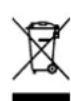
This symbol indicates that this product must not be disposed of together with domestic waste in compliance with the Directive (2012/19/EU) pertaining to waste electrical and electronic equipment (WEEE). This product must be disposed of at a designated collection point. This can occur, for example, by handing it in at an authorised collecting point for the recycling of waste electrical and electronic equipment. Improper handling of waste equipment may have negative consequences for the environment and human health due to potentially hazardous substances that are often contained in electrical and electronic equipment. By properly disposing of this product, you are also contributing to the effective use of natural resources. You can obtain information on collection points for waste equipment from your municipal administration, public waste disposal authority, an authorised body for the disposal of waste electrical and electronic equipment or your waste disposal company.
Günzburger Straße 69
D-89335 Ichenhausen
CHER CLIENT,
Günzburger Straße 69
D-89335 Ichenhausen
VÁŽENÝ ZÁKAZNÍKU,
Günzburger Straße 69
D-89335 Ichenhausen
VÁŽENÝ ZÁKAZNÍK,
Günzburger Straße 69
D-89335 Ichenhausen
TISZTELT VÁSÁRLÓ!
Günzburger Straße 69
D-89335 Ichenhausen
DROGI KLIENCIE,
Annex V
Annex VI
Notified Body:
Notified Body No.:
Noise: measured L_WA = xx dB(A) ; guaranteed L_WA = xx dB(A) P = 0.55 KW; L/∅ = cm
X 2006/42/EC
Annex IV
Notified Body:
Notified Body No.:
Certificate No.:
2010/26/EC
Emission. No:
Standard references:
EN 60745-1; EN 60745-2-1; EN 55014-1; EN 55014-2; EN 61000-3-2; EN 61000-3-3
This declaration of conformity is issued under the sole responsibility of the manufacturer.
Subject to change without notice
Documents registar: Georg Kohler
Günzburger Str. 69, D-89335 Ichenhausen
Garantiebedingungen