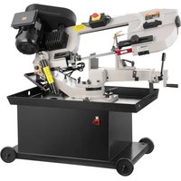
BS-712R - Saw Vevor - Free user manual and instructions
Find the device manual for free BS-712R Vevor in PDF.


User questions about BS-712R Vevor
0 question about this device. Answer the ones you know or ask your own.
Ask a new question about this device
Download the instructions for your Saw in PDF format for free! Find your manual BS-712R - Vevor and take your electronic device back in hand. On this page are published all the documents necessary for the use of your device. BS-712R by Vevor.
USER MANUAL BS-712R Vevor
Technical Support and E-Warranty Certificate
www.vevor.com/support
Metal horizontal band saw USER MANUAL
MODEL:BS-712R
We continue to be committed to provide you tools with competitive price. "Save Half", "Half Price" or any other similar expressions used by us only represent estimate of savings you might benefit from buying certain tools with us compared top brands and does not necessarily mean to cover all categories of tools offered are kindly reminded to verify carefully when you are placing an order with us actually saving half in comparison with the top major brands.
MODEL:BS-712R
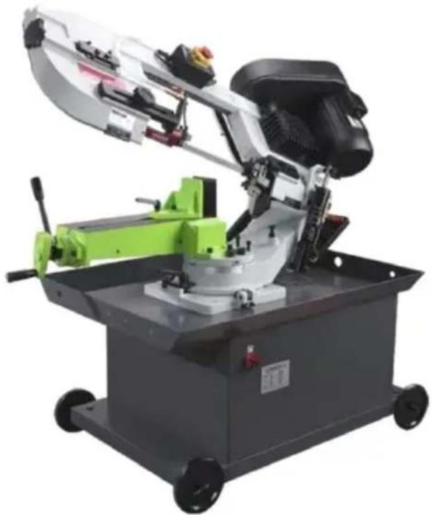
natural_image
Industrial cutting machine with green handle and black head assembly, mounted on a gray base with wheels (no visible text or symbols)(The picture is for reference only, please refer to the actual obje
NEED HELP? CONTACT US!
Have product questions? Need technical support? Please feel fr contact us:
Technical Support and E-Warranty Certificate www.vevor.com/support
This is the original instruction, please read all manual instruction carefully before operating. VEVOR reserves a clear interpretation user manual. The appearance of the product shall be subject to product you received. Please forgive us that we won't inform you there are any technology or software updates on our product.
 | Warning-To reduce the risk of injury, user must read instru manual carefully. |
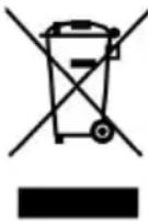 | This product is subject to the provision of European Direct 2012/19/EC. The symbol showing a wheelie bin crossed thr indicates that the product requires separate refuse collection European Union. This applies to the product and all acces marked with this symbol. Products marked as such may no discarded with normal domestic waste, but must be taken collection point for recycling electrical and electronic devices |
SAFETY INSTRUCTION
-
Know your bandsaw. Read the operator's manual carefully. Learn the operations, applications and limitation as well as the specific potential hazard peculiar to this band saw
-
This unit is equipped with a three prong (grounded) plug for your prote against shock hazards and should be plugged directly into a property grounded three prong receptacle. Where a two prong wall receptacle is encountered. It must be replaced with a properly grounded three prong receptacle in accordance with the National Electrical Code and Local Code and Ordinance.
-
Use only 3-wire extension cords which have 3-prong grounding type plug
-
Replace or repair damage or worn cord immediately.
-
Keep guards in place and in working order.
-
Be especially careful when using band saw in vertical position to keep fingers and hands out of path of blade.
-
Wear ear protection if exposed to long periods of very noisy shop oper 8. Use safety goggles, hard hat and safety shoes. Also use face or dust cutting operation is dusty.
-
Wear proper apparel. No loose clothing or jewelry to get caught in mov parts. Do not wear a tie or gloves.
-
Don't overreach. Keep your proper footing and balance at all times.
-
Secure work. Always use the vise to hold work. Clamp securely. Never hand-hold the work with saw in horizontal position.
- Keep work area clean. Cluttered areas and benches invite accidents.
- Avoid dangerous environment. Don not use the band saw in damp or location. Keep work area well illuminated.
- Don't force tool. It will do the job better and safer at the rate for which designed. 15. Disconnect power cord before adjusting and servicing and before changing blade.
- Safety is combination of operator common sense and alertness at all t when the saw is being used.
- Never stand on tool. Serious injury could occur if the tool is tipped on cutting tool is accidentally contacted.
- Check damaged parts. Before further use of the tools, a guard or other parts that will operate to assure that it will operate properly
- And perform its intend function-check for alignment of moving parts; binding of moving parts, break-age of parts, mounting and any other conditions that may affect its operation. A guard or other part that is dar should be properly repaired or replaced.
- If tool is equipped with three-prong plug, it should be plugged into a three-hole electrical receptacle. If an adapter is used to accommodate a t prong receptacle, the adapter plug must be attached to a known ground. Never remove the third prong
- When moving the saw, ALWAYS have the head lowered to the horizontal position.
ASSEMBLY
A 3/4 or 1 HP motor split phase or capacitor is recommended for best economical performance. Counter clockwise is required. Note that rotation of be reversed by following directions given on terminal or name plate.
- Assemble the motor Mounting plate to the head using the long bolt. If that the flat side of the plate faces up.
- Assemble the guard plate to the head using the screw and lock wash the carriage bolt.Washer and wing nut are used to secure the motor mount plate to the guard plate through the slotted hole in the guard plate. The
components also serve to position and lock the motor in place or proper speed/belt adjustment.
- Place the spacer over the long bolt and secure it with the nut.
- Secure the motor to the motor mounting plate with the four bolts and Note that the motor shaft is placed through the large opening in the gua and must be parallel with the drive shaft.
- Assemble the motor pulley, the smaller of the two provided to the motor shaft. Note the larger diameter must be closest to the motor. Do not tigh set screw.
- Assemble the driven pulley, the larger off the two provided to the pro drive shaft. Note the
smaller diameter must be closest to the bearing. Do not tighten the set
- Place the belt into one of the pulley groove and the other end into the respective grooves of the second pulley.
- Line up the belt and both pulleys so that the belt is running parallel pulley grooves.
-
Tighten the set screws of both pulleys in this position.
-
Place the belt into proper pulley combination for proper blade speed.
11 .Adjust the position of the motor to obtain approximately 1/2"depression the belt when applying pressure with your thumb
-
Tighten the head screw holding the motor mounting plate to the guard
-
Connect the electrical harness to the motor terminal box. The motor should be protected with a time delay fuse or circuit breaker with a rated amper slightly greater than the full-load amperage of the motor.
INSTALLATION
The saw may be mounted on your own bench or stand. The rear end of saw must be mounted flush with the rear of the stand or bench to perform vertical operation for this band saw. This stand has punched holes to effuse easy assembly to the base using eight standard bolts.
OPERATION
WORK SET UP
-
Raise the saw head to vertical position
-
Open vise to accept the piece to be cut by rotating the wheel at the base.
- Place work piece on saw bed. If the piece is long support the end.
- Clamp work piece securely in vise
WORK STOP ADJUSTMENT
- Loose the thumb holding the work stop casting to the shaft.
- Adjust the work stop casting to the desired length position.
- Rotate the work stop as close to the bottom of the cut as possible.
- Tighten thumb screw.
- Do not allow the blade to rest on the work while the motor is shut
CONVERTING FOR VERTICAL USE
Nothing, slitting, contour work may be done with the saw in the vertical in the following manner:
- Rotate the head to the vertical position.
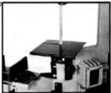
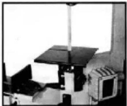
- Assemble a 10"x10" table (an option that maybe purchased from your dealer to the guide bar using the screws provided and the guide bar kn
BLADE SPEEDS
When using your band saw always change the blade speed to best suit material being cut. The material cutting shaft given suggested settings for several materials.
4 SPECIFICATION CHART
| Item No. | BS-712R |
| Voltage | 110V -220V/220v |
| Frequency | 50Hz/60Hz |
| Power | 1.1KW |
| Maximum Speed | 256fpm |
| Cut Rectangular Dimensions | 7*8.25” |
| Blade Length | 93” |
BLADE DIRECTION OF TRAVEL
Be sure the blade is assembled to the pulleys so that the vertical edge engages the work piece first.
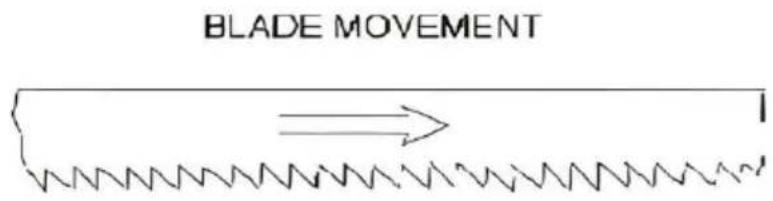
text_image
BLADE MOVEMENTSTARTING SAW
CAUTION: NEVER OPERATE SAW WITHOUT BLADE GUARDS IN PLACE. Be sure the blade is not in contact with the workpiece when the motor started. Start the motor, allow the saw to come to full speed, then begin by let the head down slowly onto the work. DO NOT DROP OR FORCE the weight of the saw head provide the cutting force. The saw automatic shuts off at the end of the cut.
BLADE SELECTION
A 8-tooth per inch, general-use blade is furnished with this metal cutting saw. Additional blades in 4,6,8 and 10 tooth sizes are available. The choice the blade pitch is governed by the thickness of the work to be cut; the the workpiece. the more teeth advised. A minimum of three teeth should engage the workpiece at all times for proper cutting. If the teeth of the are so far apart that they straddle the work, severe damage to the work and to the blade can result.
CHANGING BLADE
Raise saw head to vertical position and open the blade guards. Loosen tension screw knob sufficiently to allow the saw blade to slip off the w install the new blade with teeth slanting toward the motor as follows:
- Place the blade in between each of the guide bearings
- Slip the blade around the motor pulley (bottom) with the left hand and position.
-
Hold the blade taut against the motor pulley by pulling the blade upw the right hang which is placed at the top of the blade.
-
Remove left hand from bottom pulley and place it at the top side of to continue the application on the upward pull on the blade.
- Remove right hand from blade and adjust the position of the top pulley permit left hand to slip the blade around the pulley using the thumb index little finger as guides.
- Adjust the blade tension knob clockwise until it is just right enough so blade slippage occurs. Do not tighten excessively.
- Replace the blade guards.
- Place 2-3 drops of oil on the blade.
USAGE OF THE QUICK VISE
Your machine is equipped with a quick action vise jaw which allows you instantly position the movable vise jaw (B). Simply turn hand wheel (A) c clockwise 1/2 turn and move the vise jaw(B) to the desired position. Then tighten the vise jaw (B) against the workpiece by turning hand-wheel clockwise.
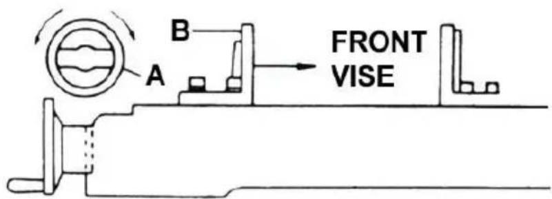
text_image
A B FRONT VISEQUICK VISE ADJUSTMENT FOR ANGLE CUT
- Loosen the A.B.C. Screw.
- Adjust rear vise to the threaded hole position.(E)
- Set the scale to the desired angle.
- Adjust the front vise (D) to parallel the rear vise (E).
- Tighten the A.B.C. Screw.
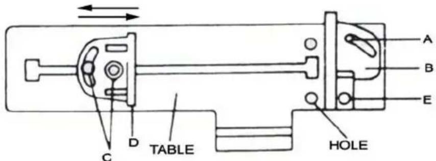
text_image
A B E C D TABLE HOLEBLADE GUIDE BEARING ADJUSTMENT
ATTENTION: This is the most important adjustment on your saw. It is impossible to get satisfactory work from your saw if the blade guides are properly adjusted. The blade guide bearing on your Metal Cutting Band S adjusted and power tested with several test cuts before leaving the factor insure proper setting. The need for adjustment will rarely occur when the is used properly. If the guides do get out of adjustment, it is extremely important to read just immediately. If improper adjustment is maintained, the blade will not cut straight, and if the situation is not corrected it will cause serious blade damage
Because guide adjustment is a critical factor in the performance of your tools is always best to try a new blade to see if this will correct poor cutting beginning to adjust. If a blade becomes dull on one side sooner than that for example, it will begin cutting crooked. A blade change will correct this problem, the guide adjustment will not. If a new blade does not correct the problem, check the blade and guides for proper spacing.
NOTE: There should be from 000 (just touching) 001 clearance between blade and guide bearings, to obtain this clearance adjust as follows.
- The inner guide bearing is fixed and cannot be adjusted.
- The outer guide bearing is mounted to an eccentric bushing and can adjusted.
- Loose the nut while holding the bolt with an Allen wrench.
- Position the eccentric by turning the bolt to the desired position of cle
- Tighten the nut.
- Adjust the second blade guide bearing in the same manner.
BLADE TRACK ADJUSTMENT
- Open the blade guard.
- Remove the blade guide assemblies (top and bottom)
- Loosen the hex head screw in the tilting mechanism to a point where loose but snug.
- With the machine running, adjust both the set screw and blade tension simultaneously to keep
constant tension on the blade. The set screw and blade tension knob are always tuned in opposite directions, when one is turned clockwise the other turned counterclockwise. The blade is tracking properly when the back side just touches the shoulder of pulley or a slight gap appears near the center of the pulley. Care should be taken not to over tighten the saw blade s will give a false adjustment and limit life of the blade.
- Tighten the hex head screw in tilting mechanism.
IMPORTANT: Sometimes for trying to make this critical adjustment it is possible causing the basic setting to be misaligned. Should this occur, pro as follows:
a. Loosen the set screw and back it out as far as it can go and still the threaded hold. b. Turn the hex head screw clockwise until it stop (do tighten).
c. Turn the set screw clockwise to the bottoms, then continue for half and check the tracking
by turning on the machine.
d. If further adjustment is required, go back to step 4.
-
Turn off power to the machine.
-
Replace the blade guide assemblies - it may be necessary to loosen blade tension lightly.
-
Adjust the vertical position of blade guide bearing assemblies so that the back side of the blade just Touches the ball bearings
-
Make a final run to check tracking. If required, touch up adjustment (step 4)
-
Replace the blade guards.
MAINTE NANCE
CAUTION: MAKE SURE THAT THE UNIT IS DISCONNECTED FROM THE POWER SOURCE BEFORE AT TEMTING TO SERVICE OR REMOVE AN COMPONENT!
LUBRICATION
Lubricate the following components using SAE-30 oil as noted.
- Ball-bearing none.
- Driven pulley bearing 6-8 drops a week.
-
Vise lead screw as needed.
-
The drive gears run in an oil bath and will not require a lubricant or more often than once a year, unless the lubricant is accidentally contaminant or a leak occurs because of improper replacement of the gear box cover. During the first few days of operation, the worm gear drive will run hot. the temperature exceeds 200F. there is no cause for alarm.
The following lubricants may be used for the gear box:
Atlantic Refinery Co. Mogul Cyl. Oil
Cities Service Optimus No.6
Gulf Refinery Co Medium Gear Oil
Pure Oil co.Park Clipper
Tools required for assembly
2 cross point screwdriver Pliers
Unpacking and clean-up
- First uncrating the saw. Inspect it for sh damage. If any damage has occurred, conta your distributor.
- Unbolt the saw from the skid and place level surface.
- Clean rust protected surfaces with kerose diesel oil. Do not use cellulose based solve such as paint thinner or lacquer thinner. Th damage painted surfaces.
Vertical cutting plate assembly
Note: these steps are only necessary if using bandsaw in the vertical mode.

Warning
Disconnect bandsaw from the power source before making any repairs or adjustments! Failure to comply may cause ser injury!

natural_image
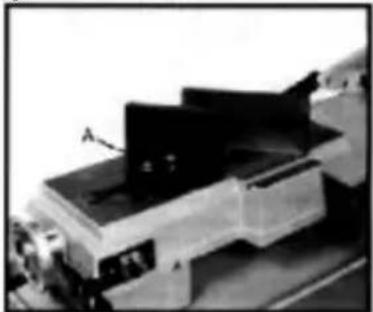
Black-and-white photo of a mechanical setup with labeled component B, no visible text or symbolsFig.1
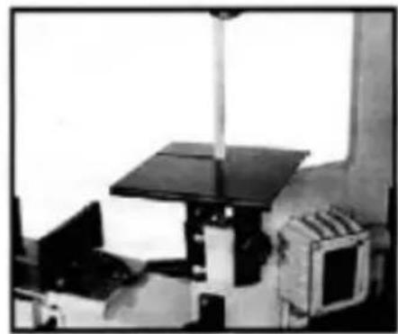
natural_image
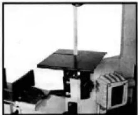
Black-and-white photo of a laboratory setup with equipment and a vertical rod (no visible text or symbols)Fig.2
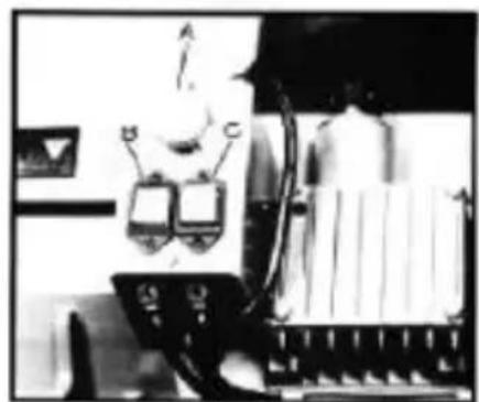
natural_image
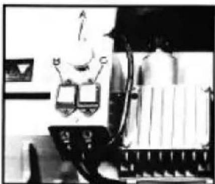
Black-and-white photo of a vintage office interior with two electronic devices and a large cylindrical device (no visible text or symbols)Fig.3
- Disconnect the bandsaw from the power source.
- Raise the arm to the vertical position and lock in place by turning the hydraulic cylinder valve to the off position.
-
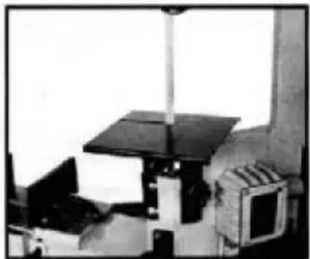
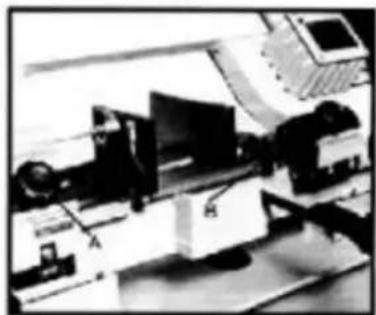
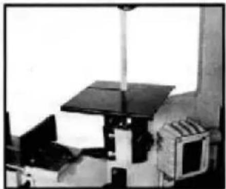
Remove two screws (A.Fig. 1) and the deflector plate (B).
-
Guide blade through slot in table and fasten two screws. See Fig.2.
Coolant tank preparation
Use of a water-soluble coolant will increase cu efficiency and prolong blade life. Do not use cutting oil as a substitute.
Change cutting oil often and follow manufacturer instructions as to its uses and precautions.
- Disconnect machine from the power source.
- Remove coolant return hose from tank cover
- Slide tank out of saw base and carefully lid containing coolant pump.
- Fill tank to approximately 80% of capacity.
- Place lid back onto tank and place tank a back into base.
- Replace return hose back into hole in tank
Adjusting blade square to table
- Disconnect machine from the power source
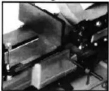
- Place machinist's square on table next to I pictured in Fig.4.
- Check to see blade contact with square all entire width of the blade.
- If adjustment is necessary, loosen bolts and blade guide
assemblies slightly in the same direction until makes contact
with the square along it's entire width.
- Tighten bolts (A).
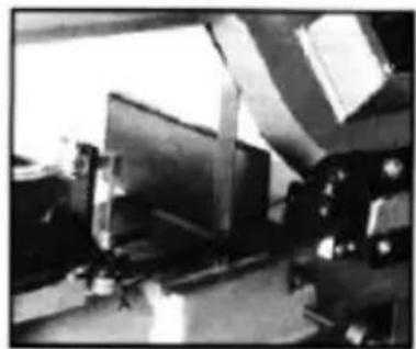
natural_image
Industrial machinery setup with metal components and a control panel (no visible text or symbols)Fig.4
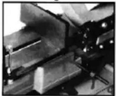
natural_image
Close-up of mechanical components with no visible text or symbolsFig.5
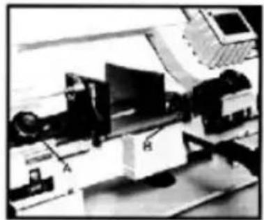
natural_image
Black-and-white photo of a laboratory instrument with labeled parts (A, H, and others), no visible text or symbols.Fig.6
natural_image
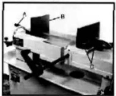
Laboratory setup with two monitors and a tripod, no visible text or symbolsFig.7
natural_image
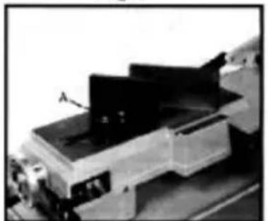
Mechanical assembly with labeled component A, no visible text or symbolsFig.8
- Connect machine to the power source
Note: If adjustment of square blade to table is necessary. be sure to change blade adjustments again. Adjusting blade square to vise
- Disconnect machine from the power source.
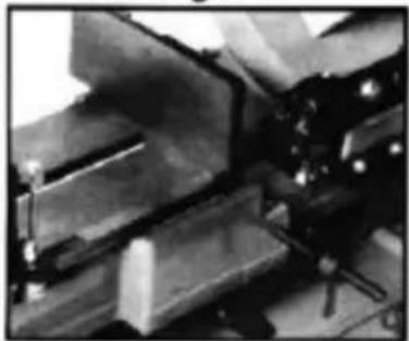
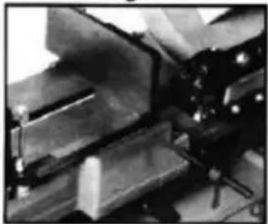
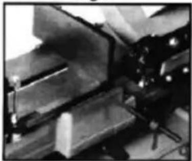
- Place a machinist's square as pictured in figure 5. Square should lie along entire length of vise and blade without a gap.
- If adjustment is necessary. loosen bolts holding vice and adjust vise so that square lines up properly. Tighten bolts.
- Connect machine to the power source.
Adjusting blade guides
- Disconnect machine from the power source
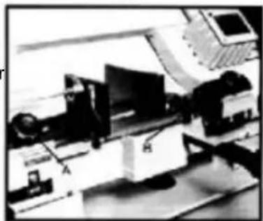
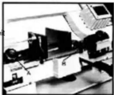
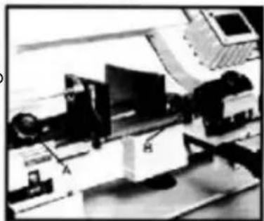
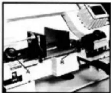
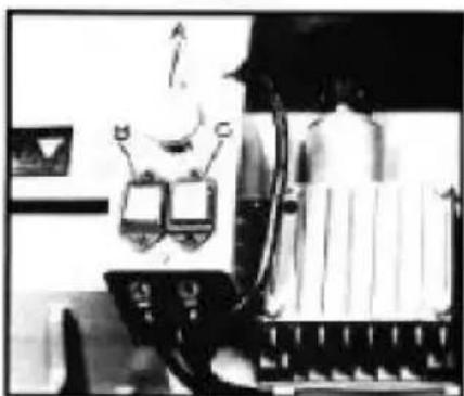
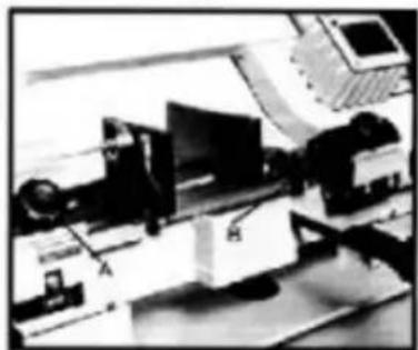
- Loosen knob(A.Fig.6) and bolt (B). Slide blade guide assemblies as clos possible to the material without touching with the cut.
- Tighten knob (A) and bolt (B) and connect machine to the power sou
Vise adjustment

Warning
Do not make any adjustments or load/unload material from vise while ma is running!
Failure to comply may cause serious injury!
o set the vise for 0 to 45 degree cutting:
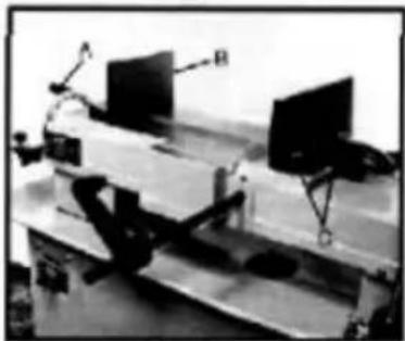
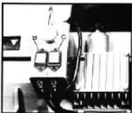
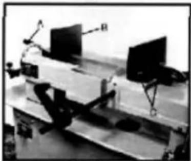
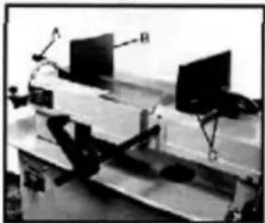
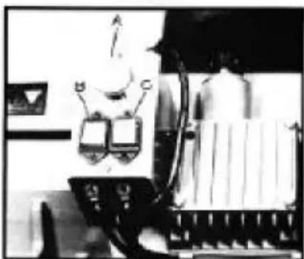
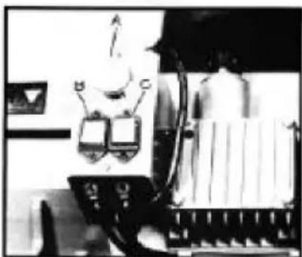
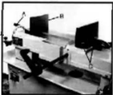
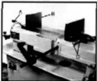
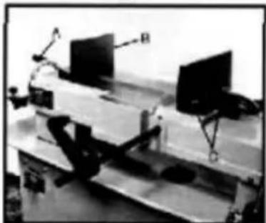
- Remove bolt assemblies(C.Fiq.7)
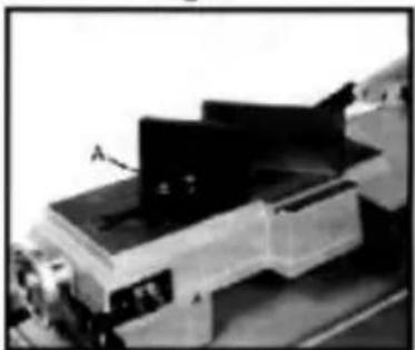
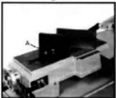
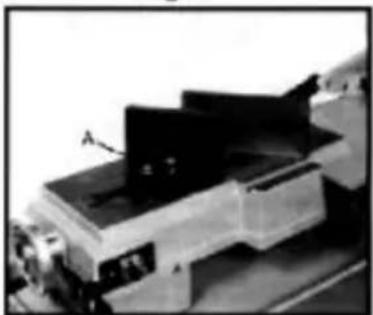
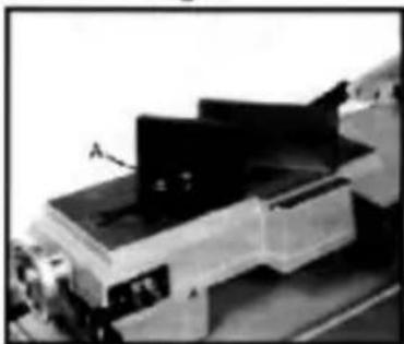
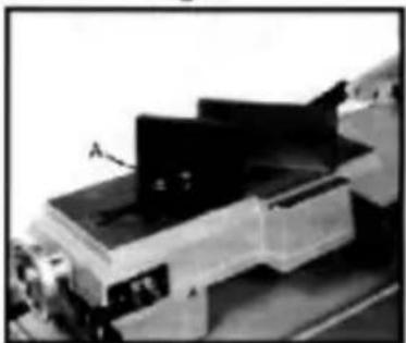
- Position vise and re-install as picture in Fig.8. Pay particular attention to bolt hole location.
- Set vise to desired angle, re-install bolts, and lighten nut and bolt assemblies.
- Adjust movable vise parallel to fix vise by loosening bolt(A, Fig.8). adjust to parallel and tightening bolt.
To set vise for maximum width of stock cutting
- Remove nut and bolt assemblies.
- Position vise and re-install bolt assemblies as pictured in Fig 7.
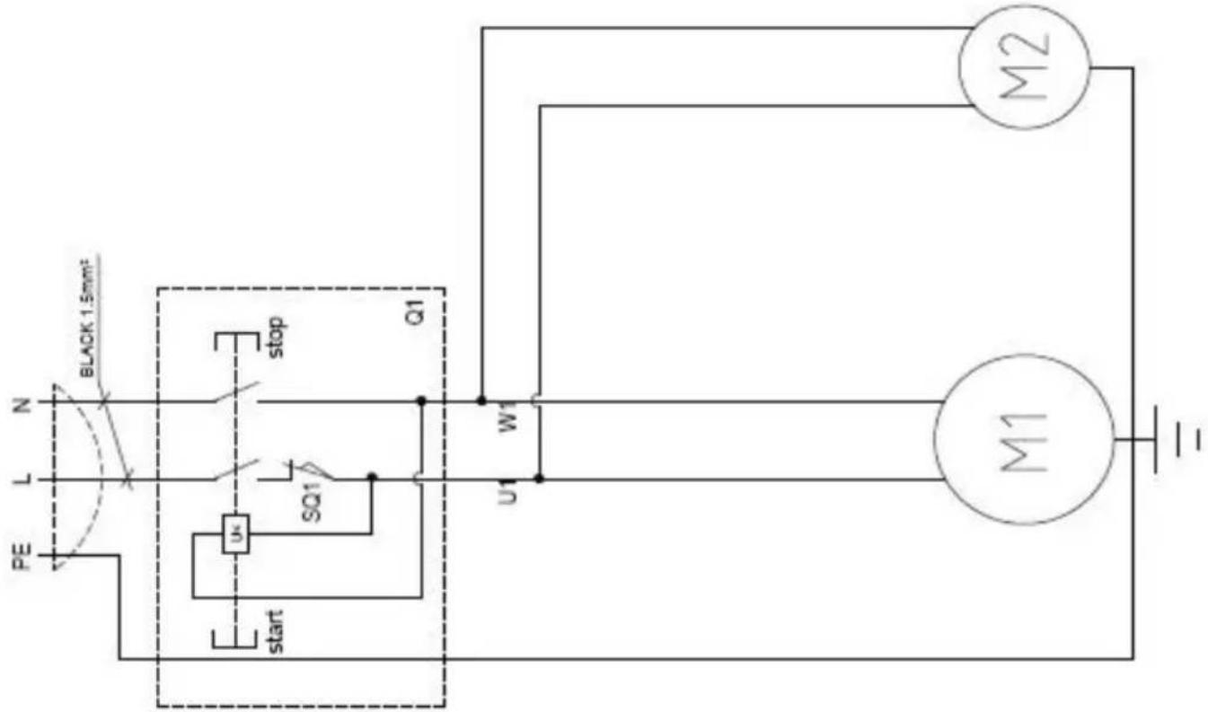
Electric principle drawing
text_image
BLACK 1.5mm² N L PE stop Q1 w1 u1 start SQ1 M2 M1Motor wiring diagram
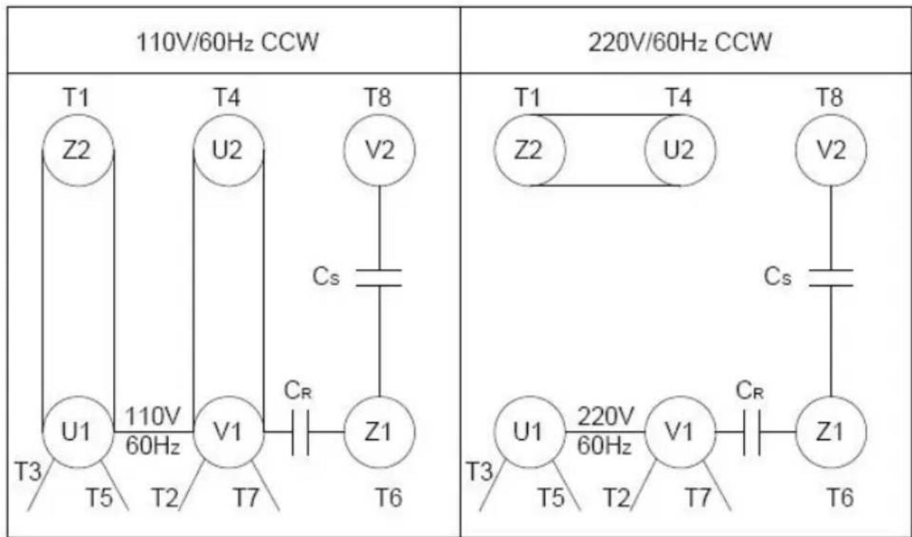
The above wiring diagram is reversed. To reverse, simply sw T5 and T6.
| Part No. | Description | Qty | Part No. | Description | Qty |
| 1 | Upper board of bottom pan | 1 | 43 | Support | 1 |
| 2 | Leg B | 1 | 44 | Bolt M6X16 | 1 |
| 3 | Leg A | 1 | 45 | Acme screw | 1 |
| 4 | Board B | 1 | 46 | Pin | 1 |
| 5 | Board A | 1 | 47 | Spring screw | 1 |
| 6 | Foot wheel φ 125X φ 12 | 4 | 48 | Bolt M5X8 | 1 |
| 7 | Pin 3X25 | 4 | 49 | Seat of stop switch | 1 |
| 8 | Foot wheel shaft | 2 | 50 | Stop switch | 1 |
| 9 | Bolt M10X30 | 2 | 51 | Washer 6 | 2 |
| 10 | Flat washer 10 | 2 | 52 | Bolt M6X12 | 1 |
| 12 | Column 12X70 | 1 | 53 | Handle assembly | 1 |
| 13 | Support for cylinder | 1 | 54 | Handle seat | 1 |
| 14 | Hydraulic cylinder | 1 | 55 | Handle shaft | 1 |
| 15 | Bolt M10X35 | 1 | 56 | Bolt M8X16 | 2 |
| 16 | Flat washer 10 | 1 | 57 | Washer 8 | 2 |
| 11 | Screw M10 | 2 | 58 | Screw M8 | 1 |
| 17 | Bolt M6X16 | 6 | 59 | Safety board | 1 |
| 18 | Washer 6 | 6 | 60 | Bolt M8X30 | 1 |
| 19 | Screw M6 | 6 | 61 | Bottom seat | 1 |
| 20 | Bolt M8X16 | 8 | 62 | fixed handle M10X80 | 1 |
| 21 | Flat washer 8 | 16 | 63 | Bolt M10X35 | 1 |
| 22 | Screw M8 | 8 | 64 | Washer 10 | 2 |
| 23 | Bolt M6X20 | 1 | 65 | Moving vise | 1 |
| 25 | filter sieve | 1 | 66 | Bolt M12X40 | 2 |
| 26 | Screw M6 | 1 | 67 | Washer 12 | 2 |
| 27 | Bolt M8X30 | 7 | 68 | Fixed vise | 1 |
| 28 | Washer 8 | 7 | 69 | Bolt M10X20 | 1 |
| 29 | Screw M8 | 7 | 70 | Washer 10 | 1 |
| 30 | Coolant switch assembly | 1 | 71 | Screw M10 | 2 |
| 31 | Coolant box | 1 | 72 | Set rack | 1 |
| 32 | Aleak hose | 1 | 73 | Bolt on Spring | 1 |
| 33 | Coolant pump | 1 | 74 | Spring | 1 |
| 34 | Bolt M6X16 | 4 | 75 | Bolt M10X40 | 1 |
| 35 | Coupler | 1 | 76 | Screw M10 | 1 |
| 36 | Hose clamp | 1 | 77 | Bolt M10X35 | 2 |
| 37 | Hose | 1 | 78 | Mat | 1 |
| 38 | Turning handle M8X63 | 1 | 79 | Pivot arm | 1 |
| 39 | Hand wheel φ 125X φ 15 | 1 | 80 | Rotor | 1 |
| 40 | Bolt M6X6 | 1 | 81 | Sleeve | 2 |
| 41 | Key 5X20 | 1 | 82 | Washer 16 | 2 |
| 42 | Screw | 1 | 83 | Screw M10 | 2 |
| 84 | Support | 1 | 123 | Nozzle support | 1 |
| 85 | Bolt M10X40 | 1 | 124 | Coolant switch assembly | 1 |
| 86 | Screw M10 | 1 | 125 | Bolt M8X30 | 1 |
| 87 | Bolt M10X35 | 2 | 126 | Screw M10X1 | 4 |
| 88 | Washer 10 | 2 | 126.1 | Washer 10 | 4 |
| 89 | fixed board for cylinder | 1 | 127 | Shaft | 2 |
| 90 | Bolt M8X30 | 3 | 128 | Bolt M4X6 | 2 |
| 91 | Shaft on cylinder | 1 | 129 | Bearing 608-2Z | 2 |
| 92 | Bolt M8X16 | 2 | 130 | Shaft | 2 |
| Big washer 8 | 2 | 131 | Eccentric shaft | 2 | |
| 93 | Bolt M10X45 | 1 | 132 | Bearing 608-2Z | 8 |
| 94 | Washer 10 | 1 | 133 | Washer 8 | 4 |
| Screw M10 | 1 | 134 | Bolt M5X12 | 2 | |
| 95 | Bolt M8X16 | 2 | 135 | Safety board | 1 |
| 96 | Washer 8 | 2 | 136 | Bolt M8X30 | 1 |
| 97 | Blade guard | 1 | 137 | Front adjustable seat | 1 |
| 97.1 | Board | 1 | 137.1 | Rear adjustable seat | |
| 98 | Bolt M8X16 | 4 | 138 | Front adjustable support | 1 |
| 99 | Washer 8 | 4 | 139 | Thicker washer 10 | 2 |
| 100 | Bolt M8X20 | 1 | 140 | Bolt M10X40 | 1 |
| 101 | Big washer | 1 | 141 | Bolt M5X10 | 2 |
| 102 | Bearing 6203-2Z | 2 | 142 | Stand of Brush | 1 |
| 103 | Idle wheel | 1 | 143 | Brush | 1 |
| 103.1 | Steering wheel | 1 | 144 -1 | Sleeve 1 | 1 |
| 104 | Blade 2362X0.9X20 | 1 | 144 -2 | Sleeve 2 | 1 |
| 105 | Sleeve | 1 | 144 -3 | Sleeve 3 | 1 |
| 106 | Saw bow | 1 | 145 | Spring | 1 |
| 107 | Stellate handle M10X35 | 1 | 146 | Bolt M6X6 | 1 |
| 108 | Spring | 1 | 147 | Switch box | 1 |
| 109 | Board | 2 | 148 | Bolt M10X25 | 1 |
| 110 | Washer 6 | 4 | 149 | Washer | 1 |
| 111 | Bolt M6X16 | 4 | 150 | Key 6X25 | 1 |
| 112 | Shaft | 1 | 151 | Sleeve | 1 |
| 113 | Shaft seat | 1 | 152 | Gear box | 1 |
| 114 | Pin 4X20 | 1 | 152.1 | Bolt M8X16 | 1 |
| 115 | Moving board | 1 | 153 | Bearing 6005-2Z | 3 |
| 116 | Bolt M8X16 | 1 | 154 | Washer 47 | 2 |
| 117 | Bolt M8X35 | 2 | 155 | Seal 47X 25X7 | 1 |
| 118 | Washer 8 | 2 | 156 | Mat | 1 |
| 119 | Rear adjustable stand | 1 | 157 | Output shaft | 1 |
| 120 | Stellate handle M10X35 | 1 | 157.1 | Key 6X25 | 1 |
| 121 | 6 Copper tube | 1 | 158 | Washer 25 | 2 |
| 122 | Bolt M6X6 | 1 | 159 | Worm wheel | 1 |
| 160 | Seal mat | 1 | 203 | Vertical table | 1 |
| 161 | Cover for gear box | 1 | 204 | Gear box assembly | |
| 162 | Washer 6 | 4 | 205 | Vertical motor | 1 |
| 163 | Bolt M6X20 | 4 | 206 | Bolt M6X25 | 5 |
| 164 | Bolt | 1 | 207 | Bolt | 1 |
| 165 | Upper seat for cylinder | 1 | 208 | Bearing 6201-2Z | 5 |
| 166 | Washer 10 | 2 | 209 | Timing gear | 1 |
| 167 | Bolt M10X20 | 2 | 210 | Output shaft | 1 |
| 168 | Fixed seat for cylinder | 1 | 211 | Key 5X80 | 1 |
| 169 | Washer 8 | 3 | 212 | Key | 1 |
| 170 | Bolt M8X30 | 3 | 213 | Washer 25 | 3 |
| 171 | Bolt M4X12 | 3 | 214 | Bearing 6205-2Z | 2 |
| 172 | Cover for bearing | 1 | 215 | Mat | 1 |
| 173 | Washer 17 | 1 | 216 | Set board | 1 |
| 174 | Bearing 6003-2Z | 3 | 217 | Bolt M4X8 | 3 |
| 175 | Seal φ 35X17X7 | 1 | 218 | Conical pin | 1 |
| 176 | Sleeve | 1 | 219 | Poking board | 1 |
| 177 | Worm | 1 | 220 | Pin | 1 |
| 178 | Shield leathern | 1 | 221 | Spring | 1 |
| 179 | Washer 6 | 2 | 222 | Handle | 1 |
| 180 | Bolt M6X12 | 2 | 223 | O-ring 6X1.8 | 1 |
| 181 | Seating board for motor | 1 | 224 | Shaft | 1 |
| 182 | Bolt M8X40 | 1 | 225 | Bolt M5X20 | 1 |
| 183 | Screw M8 | 1 | 226 | Seal φ 30X φ 42X7 | 1 |
| 184 | Washer 8 | 3 | 227 | Gear box | 1 |
| 185 | Bolt M8X20 | 3 | 228 | Gear shaft | 1 |
| 186 | Bolt M8X50 | 2 | 229 | Gear shaft | 1 |
| 187 | Screw M8 | 2 | 230 | Key 6X20 | 1 |
| 188 | Motor seat A | 1 | 231 | Worm gear | 1 |
| 189 | Motor | 1 | 232 | Washer 20 | 1 |
| 190 | Bolt M8X25 | 4 | 233 | Seal mat | 1 |
| 191 | Washer 8 | 8 | 234 | Column pin 6X25 | 2 |
| 192 | Screw M8 | 4 | 235 | Cover for gear box | 1 |
| 193 | Key 6 | 1 | 236 | Worm | 1 |
| 194 | Stellate handle | 1 | 237 | Shaft | 1 |
| 195 | Belt cover | 1 | 238 | Bolt M6X20 | 1 |
| 196 | Bolt M8X10 | 2 | 239 | Turning handle M8X63 | 1 |
| 197 | Worm pulley | 1 | 240 | Screw M10 | 1 |
| 198 | Bolt M8X10 | 1 | 241 | Handle | 1 |
| 199 | Motor pulley | 1 | 242 | Bolt M6X12 | 1 |
| 200 | Belt | 1 | 243 | Pin 5X25 | 2 |
| 201 | Washer 6 | 2 | 244 | Speedy fixed block | 1 |
| 202 | Bolt M6X12 | 2 | 245 | Speedy moving block | 1 |
| 246 | Bolt M8X30 | 2 | 288 | Screw M10 | 1 |
| 247 | Washer 8 | 2 | 289 | Bolt M6X25 | 2 |
| 248 | Bearing 51101 | 1 | 290 | Seat | 1 |
| 249 | Mat 14 | 1 | 291 | Bottom tray | 1 |
| 250 | Spring | 1 | 292 | Bolt M8X25 | 4 |
| 251 | Handle pole | 1 | 293 | Tray | 1 |
| 252 | Handle cover M12X60 | 1 | 294 | Upper plate of stand | 1 |
| 253 | Screw | 1 | 295 | Block | 1 |
| 254 | Adjustive screw | 1 | 296 | Screw M8 | 1 |
| 255 | Vice | 1 | 297 | Bolt M8X40 | 1 |
| 256 | Moving vise | 1 | 298 | Shaft | 1 |
| 257 | Washer 10 | 2 | 299 | Fixed seat | 1 |
| 258 | Adjustable fixed handle M10X80 | 1 | 300 | Bolt M8X25 | 1 |
| 259 | Bolt M10X35 | 1 | 301 | Washer 8 | 2 |
| 260 | Fixed vise | 1 | 302 | Middle plate of stand | 2 |
| 261 | Washer 8 | 3 | 302.1 | Middle plate of stand | 1 |
| 262 | Bolt M8X30 | 3 | 303 | Washer 8 | 4 |
| 263 | Bolt M10X30 | 4 | 304 | Stretchy washer 16 | 4 |
| 264 | Washer 10 | 4 | 305 | Bolt M8X25 | 4 |
| 265 | Bolt M8X16 | 1 | 306 | Lower plate of stand | 1 |
| 266 | Key 8X100 | 1 | 307 | Screw M8 | 22 |
| 267 | Bolt M8X25 | 6 | 308 | Washer 8 | 44 |
| 268 | Sleeve | 2 | 309 | Bolt M8X16 | 22 |
| 269 | Rotative tray | 1 | 310 | Foot wheel | 4 |
| 270 | Bolt M16X65 | 1 | 311 | Foot wheel shaft | 2 |
| 271 | Bolt 12X16 | 4 | 312 | Pin 3X25 | 4 |
| 272 | Spring | 4 | 313 | Bolt M8X16 | 2 |
| 273 | Shaft | 4 | 314 | Big washer 8 | 2 |
| 274 | Rotative sleeve | 1 | 315 | Shaft | 1 |
| 275 | Stretchy washer 16 | 1 | 316 | Screw M12 | 1 |
| 276 | Washer 16 | 1 | 317 | Bolt M12X60 | 1 |
| 277 | Capper | 1 | 318 | Breakwater | 1 |
| 278 | Rotation | 1 | 319 | Bolt M6X12 | 2 |
| 279 | Spring | 1 | 320 | Washer 6 | 2 |
| 280 | Bolt for spring | 1 | 321 | Sleeve | 1 |
| 281 | Screw M10 | 2 | 322 | Handle seat | 1 |
| 282 | Fixed board | 1 | 323 | Handle shaft | 1 |
| 283 | Bolt M8X20 | 1 | 324 | Key 5X20 | 1 |
| 284 | Adjustable fixed handle M10X80 | 1 | 325 | Screw | 1 |
| 285 | Board | 1 | 326 | Vice | 1 |
| 286 | Scale | 1 | 327 | Key 8X70 | 1 |
| 287 | Bolt M10X40 | 1 | 328 | Rotative tray | 1 |
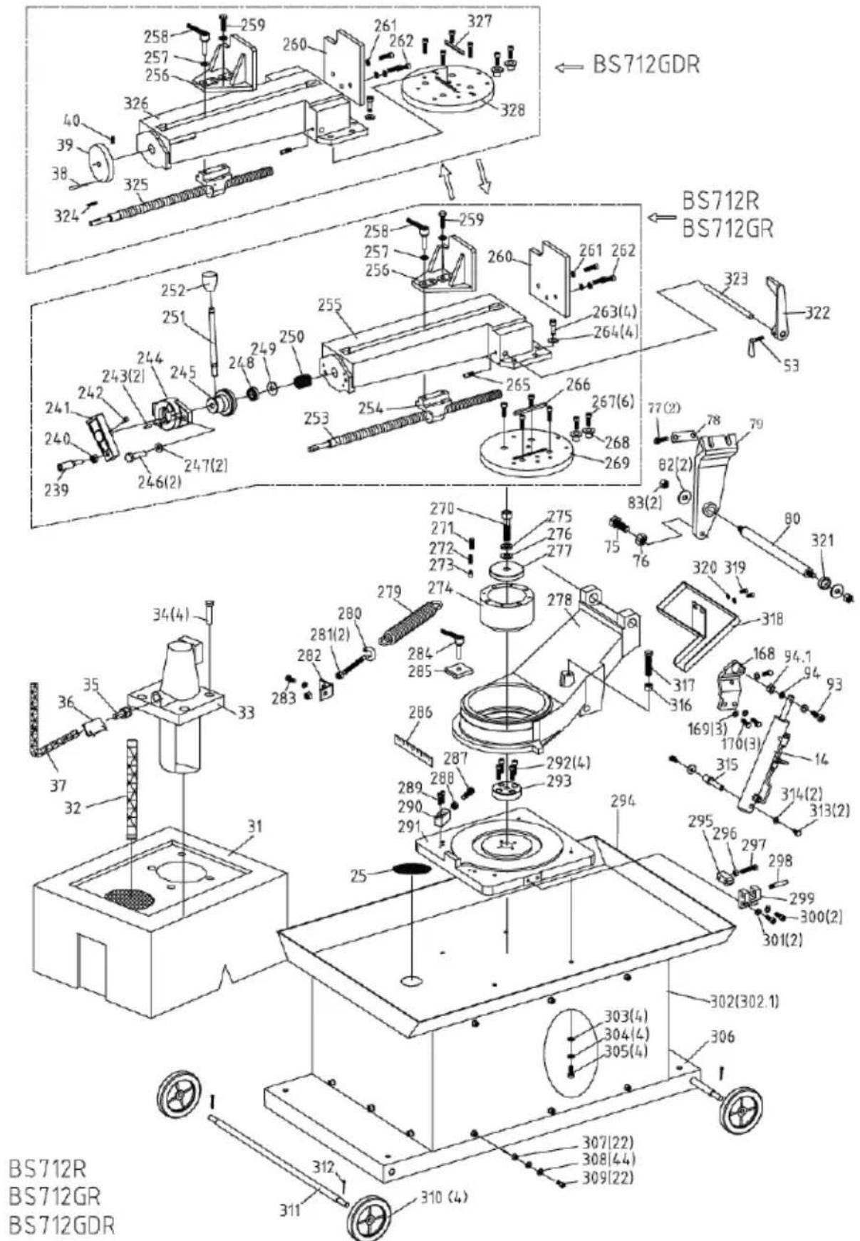
text_image
BS712GDR BS712R BS712GR 323 322 53 258 257 256 260 261 262 327 328 40 39 38 324 252 251 248 249 250 255 258 257 256 260 261 262 263(4) 264(4) 265 266 267(6) 268 269 77(2) 78 79 82(2) 83(2) 320 319 318 317 316 168 94.1 94 93 170(3) 14 315 314(2) 313(2) 295 296 297 298 299 300(2) 301(2) 302(302.1) 306 BS712R BS712GR BS712GDRVEVOR®
TOUGH TOOLS, HALF PRICE
Technical Support and E-Warranty Certificate www.vevor.com/support
VEVOR®
TOUGH TOOLS, HALF PRICE
natural_image
Industrial cutting machine with green and black components mounted on a gray base (no visible text or symbols)text_image
Diagram showing a zigzag line with an arrow indicating direction, possibly representing a transformation or process.DÉMARRAGE DE LA SCIE
ATTENTION : NE JAMAIS UTILISER LA SCIE SANS LES PROTECTIONS DE LAME EN PLACE.
REEMPLACEMENT DE LA LAME
text_image
A B E C D TABLE HOLERÉGLAGE DU ROULEMENT DE GUIDAGE DE LAME
natural_image
Black-and-white photo of a laboratory setup with equipment and a computer monitor (no visible text or symbols)Fig.1
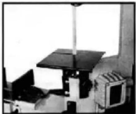
natural_image
Industrial machine setup with a black roof-mounted unit and a brick chamber (no visible text or symbols)Fig.2
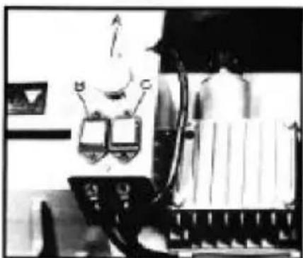
natural_image
Black-and-white photo of a robotic arm with two control panels and a cylindrical device (no visible text or symbols)Fig.3
natural_image
Interior view of a mechanical or industrial setting with multiple monitors and structural components (no visible text or symbols)Fig.4
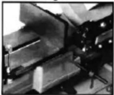
natural_image
Close-up of mechanical components with no visible text or symbolsFig.5
natural_image
Black-and-white photo of an open laboratory bench with equipment and a monitor (no visible text or labels)Fig.6
natural_image
Black-and-white photo of a desktop computer setup with two monitors and a tripod stand (no visible text or symbols)Fig.7
natural_image
Mechanical assembly or machine component with no visible text or symbolsFig.8
www.vevor.com/support
Horizontale Metallbandsäge
BENUTZERHANDBUCH
MODELL:BS-712R
natural_image
Industrial cutting machine with green and black components mounted on a gray base (no visible text or symbols)text_image
Diagram showing a zigzag line with an arrow indicating direction, possibly representing a transformation or process.STARTSÄGE
text_image
A B E C D TABLE HOLEnatural_image
Black-and-white photo of a laboratory setup with equipment and a computer monitor (no visible text or symbols)Fig.1
natural_image
Industrial machine setup with a roof-mounted platform and control panel (no visible text or symbols)Fig.2
natural_image
Black-and-white photo of a robotic arm with two control panels and a cylindrical device (no visible text or symbols)Fig.3
natural_image
Interior view of a mechanical or industrial setting with multiple monitors and structural components (no visible text or symbols)Fig.4
natural_image
Close-up of mechanical components with no visible text or symbolsFig.5
natural_image
Black-and-white photo of an electronic device with mounted components and a screen (no visible text or symbols)Fig.6
natural_image
Black-and-white photo of a desktop computer setup with two monitors and a tripod stand (no visible text or symbols)Fig.7
natural_image
Exterior view of a modern office building (no signage)Fig.8
elettronica www.vevor.com/support
natural_image
Industrial cutting machine with green and black components mounted on a gray base (no visible text or symbols)text_image
Diagram showing a zigzag line with an arrow indicating direction, possibly representing a transformation or process.text_image
A B E C D TABLE HOLEAtlantic Refinery Co. Mogul Cyl. Olio
natural_image
Black-and-white photo of a laboratory setup with equipment and a computer monitor (no visible text or symbols)Fig.1
natural_image
Industrial machine setup with a black roof and control panel (no visible text or symbols)Fig.2
natural_image
Black-and-white photo of a robotic arm with two control panels and a cylindrical device (no visible text or symbols)Fig.3
natural_image
Interior view of a mechanical or industrial setting with multiple monitors and structural components (no visible text or symbols)Fig.4
natural_image
Close-up of mechanical components with no visible text or symbolsFig.5
natural_image
Black-and-white photo of a vintage office setup with monitor, keyboard, and equipment (no visible text or symbols)Fig.6
natural_image
Black-and-white photo of a desktop computer setup with two monitors and a person using a device (no visible text or symbols)Fig.7

natural_image
Mechanical assembly or machine component with no visible text or symbolsFig.8
natural_image
Industrial cutting machine with green and black components mounted on a gray base (no visible text or symbols)text_image
Diagram showing a zigzag line with an arrow indicating direction, possibly representing a transformation or process.SIERRA DE ARRANQUE
text_image
A B E C D TABLE HOLEAJUSTE DEL COJINETE DE LA GUÍA DE LA HOJA
natural_image
Black-and-white photo of a laboratory setup with equipment and a computer monitor (no visible text or symbols)Fig.1
natural_image
Industrial machine setup with a black roof-mounted unit and a brick chamber (no visible text or symbols)Fig.2
natural_image
Black-and-white photo of a robotic arm with two control panels and a cylindrical device (no visible text or symbols)Fig.3
natural_image
Interior view of a mechanical or industrial setting with multiple monitors and structural components (no visible text or symbols)Fig.4

natural_image
Close-up of mechanical components with no visible text or symbolsFig.5
natural_image
Black-and-white photo of a vintage office setup with monitor, keyboard, and equipment (no visible text or symbols)Fig.6

natural_image
Black-and-white photo of a desktop computer setup with two monitors and a mouse, no visible text or symbolsFig.7
natural_image
Mechanical assembly or machine component with no visible text or symbolsFig.8
natural_image
Industrial cutting machine with green and black components mounted on a gray base (no visible text or symbols)text_image
Diagram showing a zigzag line with an arrow indicating direction, possibly representing a transformation or process.URUCHOMIENIE PIŁY
UWAGA: NIGDY NIE UŻYWAJ PIŁY BEZ ZAŁOŻONYCH OSŁON OSTRZA.
text_image
A B E C D TABLE HOLEAtlantic Refinery Co. Mogul Cyl. Oil
natural_image
Black-and-white photo of a laboratory setup with equipment and a computer monitor (no visible text or symbols)Fig.1
natural_image
Industrial machine setup with a black roof and control panel (no visible text or symbols)Fig.2
natural_image
Black-and-white photo of a robotic arm with two control panels and a cylindrical device (no visible text or symbols)Fig.3
natural_image
Interior view of a mechanical or industrial setting with multiple monitors and structural components (no visible text or symbols)Fig.4
natural_image
Close-up of mechanical components with no visible text or symbolsFig.5
natural_image
Black-and-white photo of a vintage office setup with monitor, keyboard, and equipment (no visible text or symbols)Fig.6
natural_image
Black-and-white photo of a desktop computer setup with two monitors and a tripod stand (no visible text or symbols)Fig.7
natural_image
Mechanical assembly or machine component with no visible text or symbolsFig.8
www.vevor.com/support
natural_image
Industrial cutting machine with green and black components mounted on a gray base (no visible text or symbols)HULP NODIG? NEEM CONTACT MET ONS OP!
www.vevor.com/support
text_image
BLADE MOVEMENTSTARTZAAG
LET OP: GEBRUIK DE ZAAG NOOIT ZONDER DAT DE ZAAGBLADBESCHERMERS ZIJN GEPLAATST.
text_image
A B E C D TABLE HOLEAFSTELLING VAN HET LAGER VAN DE BLADGELEIDER
Atlantic Refinery Co. Mogul Cyl. Olie
natural_image
Black-and-white photo of a laboratory setup with equipment and a computer monitor (no visible text or symbols)Fig.1
natural_image
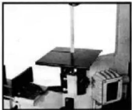
Industrial machine setup with a black roof-mounted unit and a brick chamber (no visible text or symbols)Fig.2
natural_image
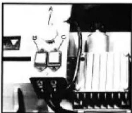
Black-and-white photo of a robotic arm with two control panels and a cylindrical device (no visible text or symbols)Fig.3
natural_image
Black-and-white photo of industrial machinery with no visible text or symbolsFig.4
natural_image
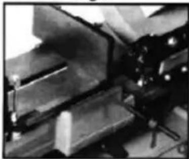
Close-up of mechanical components with no visible text or symbolsFig.5
natural_image
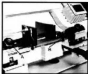
Black-and-white photo of a laboratory setup with equipment and a monitor (no visible text or symbols)Fig.6
natural_image
Black-and-white photo of a laboratory setup with two computer monitors and a tripod-mounted probe (no visible text or labels)Fig.7
natural_image
Mechanical assembly with black components and a labeled arrow (no visible text or symbols)Fig.8
www.vevor.com/support
Horisontell bandsåg i metall ANVÄNDARMANUAL
MODELL: BS-712R
natural_image
Industrial cutting machine with green and black components mounted on a gray base (no visible text or symbols)text_image
BLADE MOVEMENTSTARTSÅG
FÖRSIKTIGHET: ANVÄND ALDRIG sågen UTAN BLADSKYDD PÅ PLATS.
text_image
A B E C D TABLE HOLEJUSTERING AV BLADGUIDELAGER
Atlantic Refinery Co. Mogul Cyl. Olja
Städer Service Optimus No.6
Gulf Refinery Co Medium Gear Oil
Pure Oil co.Park Clipper
natural_image
Black-and-white photo of a laboratory setup with equipment and a computer monitor (no visible text or symbols)Fig.1
natural_image
Industrial machine setup with a black roof and control panel (no visible text or symbols)Fig.2
natural_image
Black-and-white photo of a robotic arm with two control panels and a cylindrical device (no visible text or symbols)Fig.3
natural_image
Interior view of a mechanical or industrial setting with multiple monitors and structural components (no visible text or symbols)Fig.4
natural_image
Close-up of mechanical components with no visible text or symbolsFig.5
natural_image
Black-and-white photo of an open laboratory setup with equipment and a monitor (no visible text or labels)Fig.6
natural_image
Black-and-white photo of a laboratory setup with two computer monitors and a tripod-mounted probe (no visible text or labels)Fig.7
natural_image
Mechanical assembly with layered components and a labeled component (no visible text or symbols)Fig.8