
AM877D+ - Hot air soldering station Vevor - Free user manual and instructions
Find the device manual for free AM877D+ Vevor in PDF.

| Product Type | 2-in-1 Hot Air Soldering Station |
| Brand | Vevor |
| Model | AM877D+ |
| Dimensions (L x W x H) | 280 x 260 x 160 mm |
| Net Weight | Approximately 2.95 kg |
| Input Voltage | 230 VAC ±10% 50 Hz (selectable 120 VAC ±10% 60 Hz) |
| Total Power | 820 W |
| Hot Air Station Power | 750 W |
| Soldering Station Power | 70 W |
| Hot Air Temperature Range | 100 °C to 500 °C (212 °F to 932 °F) |
| Soldering Iron Temperature Range | 150 °C to 480 °C (302 °F to 896 °F) |
| Maximum Airflow | 120 L/min |
| Air Volume Adjustment | F1 to F20 |
| Hot Air Handle Cable Length | 95 cm |
| Soldering Iron Handle Cable Length | 120 cm |
| USB Output | DC 5 V / 1 A |
| Main Functions | Hot air soldering and desoldering, soldering iron, standby and sleep mode, temperature calibration, °C/°F unit conversion |
| Package Contents | 2-in-1 rework station, soldering iron handle, stand with sponge, 3 nozzles (5, 8, 12 mm), desoldering pump, tweezers, 5 soldering tips, 30g solder wire, manual, gun stand with screws |
| Maintenance and Cleaning | Regular tip cleaning, applying new solder, replacing heating element if necessary, periodic calibration |
| Safety | Ventilation stop at 100 °C, do not direct towards people or animals, use on fireproof surface, unplug before maintenance |
| Spare Parts and Repairability | Replaceable heating element and tips, one-year limited warranty (excluding consumables) |
| General Information | Manufacturer: Shanghaimuxinmuyeyouxiangongsi, Shanghai. Imported into the USA by Sanven Technology Ltd. Support: www.vevor.com/support |
Frequently Asked Questions - AM877D+ Vevor
User questions about AM877D+ Vevor
0 question about this device. Answer the ones you know or ask your own.
Ask a new question about this device
Download the instructions for your Hot air soldering station in PDF format for free! Find your manual AM877D+ - Vevor and take your electronic device back in hand. On this page are published all the documents necessary for the use of your device. AM877D+ by Vevor.
USER MANUAL AM877D+ Vevor
Technical Support and E-Warranty Certificate www.vevor.com/support
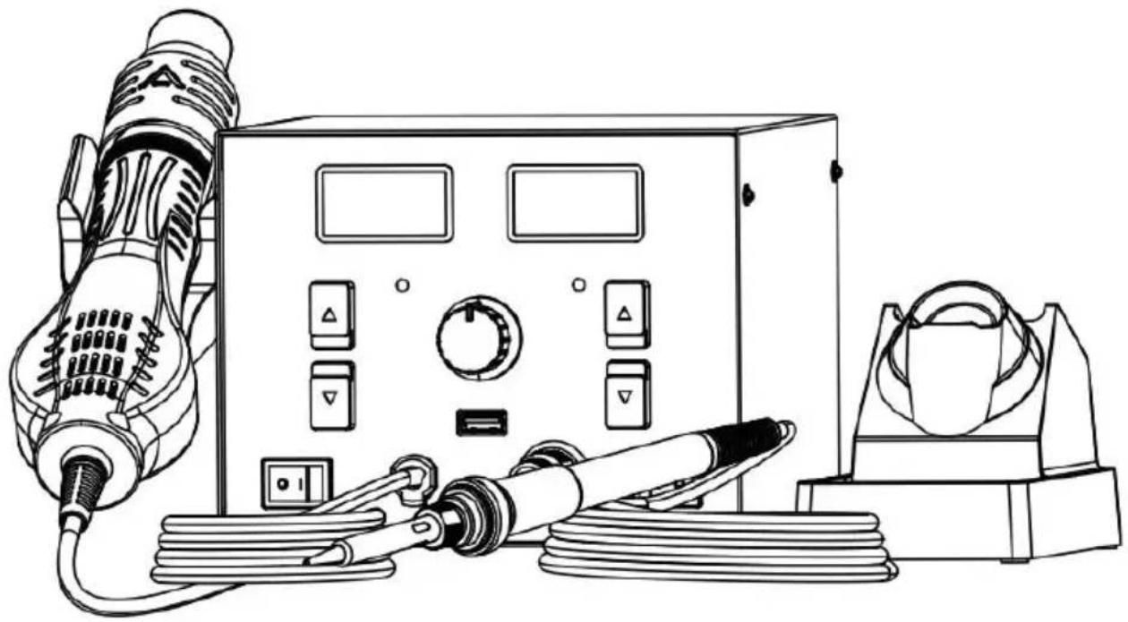
Two-in-One Hot Air Rework Station Model: AM877D+
We continue to be committed to provide you tools with competitive price. "Save Half", "Half Price" or any other similar expressions used by us only represents an estimate of savings you might benefit from buying certain tools with us compared to the major top brands and does not necessarily mean to co all categories of tools offered by us. You are kindly reminded to verify carefully when you are placing an order with us if you are actually Saving Half in comparison with the top major brands.
Model: AM877D+
natural_image
Line drawing of a portable electronic device with control panel, hose, and earpiece (no text or symbols)NEED HELP? CONTACT US!
Have product questions? Need technical support? Please feel from contact us:
Technical Support and E-Warranty Certificate www.vevor.com/support
This is the original instruction, please read all manual instruction carefully before operating. VEVOR reserves a clear interpretation user manual. The appearance of the product shall be subject to product you received. Please forgive us that we won't inform you there are any technology or software updates on our product.
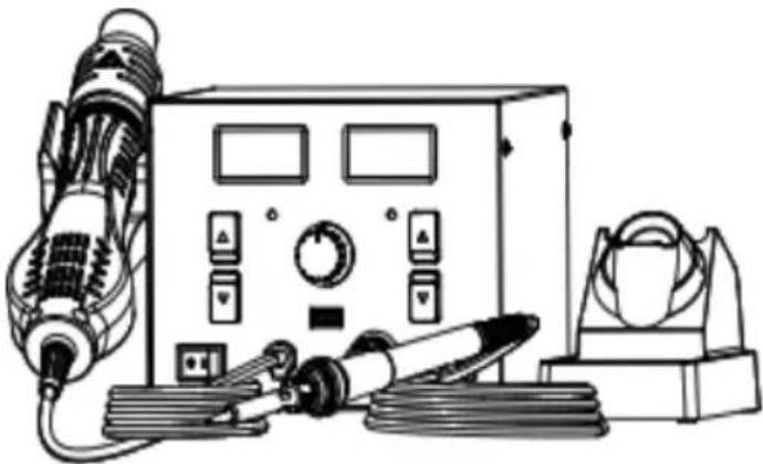
PACKING LIST
Two-in-one rework station(with air gun): 1pc
Soldering iron handle : 1pc
Iron stand (provided with cleaning sponge): 1pc
Nozzle(Φ5 mm, Φ8mm, Φ12mm): 3pcs
Desoldering pump : 1 pc
Tweezer: 1pc
Soldering tip: 5pcs
30g lead free solder wire : 1pc
User manual: 1pc
Air gun holder: 1pc with 2screws
natural_image
Line drawing of an electrical testing device with hoses, control panel, and speaker (no text or symbols)SAFETY AND PRECAUTIONS
The precautions in this manual are divided into the following [warning] and [attention].
Warning: misuse may cause death or serious injury to the user
Note: misuse may cause injury to users or substantial damage to objects inv
For your own safety, please strictly abide by the following precautions
| Warning |
| As the ambient temperature of nozzle is up to 500°C, if it is imp used ,it might hurt people and cause fire and other accidents. The please abide by the following precautions: |
| Don't aim the nozzle of hot air rework station at people or animals, the hot air rework station as a hair dryer in any case,and don't touch heating tube or use the air duct of hot air rework station to blow ski Don't put the hot air rework station nearby inflammable gas or otherinflammable substances immediately after use.The power switch should be turned off after use,and the main powe be turned off only when the temperature of hot air rework station is n 100 °C .Please use the hot air rework station carefully,don't drop or violently the machine,don't put heavy objects onto the equipment,and don't opera machine buttons or keys roughly.Don't use the hot air rework station when your hand is wet or the air rework station is wet,in order to avoid short circuit or electric shockDon't allow children to touch the product.Please use the nozzle provided by the manufacturer and don't alterThe temperature of nozzles of different models is different,which is normal,rather than quality problem with the equipment.Please notice the specification of input power when using the hot a station.The manufacturer can provide hot air rework stations of different power supplies,and please select carefully.Please don't play when using the equipment,which might hurt you or people. |
PRODUCT SPECIFICATION
| Input voltage | 230VAC±10% 50HZ (selectable within 120VAC±10% 60HZ) | |
| Total Power | 820W | |
| USB Output | DC 5V/1A | |
| Hot air rework station | Soldering station | |
| Power | 750W | 70W |
| Temperature range | 100°C~500°C (212~932 °F) | 150°C~480°C (302~896°F) |
| Handle wire length | 95cm (L) | 120cm (L) |
| Air volume gear | F1-F20 | |
| Air supply mode | Turbofan air supply | |
| Air flom rate | 120L/min (MAX) | |
| Machine Size | 280(L) x 2 60(W) x 160(H) |
| Net weight | About 2.95kg |
USING METHOD
1. Operation and display instructions
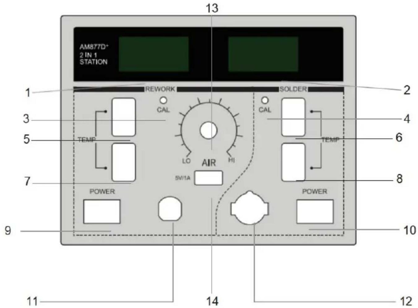
- Hot blast temperature 2. Soldering station temperature
- Hot-air calibration hole 4. Soldering iron calibration hole
- Hot blast temperature + 6. Soldering station temperature +
- Hot blast temperature - 8. Soldering station temperature -
-
Hot air switch 10. Soldering station switch
-
Hot air rework station handle interface
-
Soldering station handle interface
-
Regulating air volume 14. DC 5V/1A USB port
2. Power-on
2.1 Electrify the machine and turn on the power switch on the back.(Before turning on the power switch reconfirm that the power supply meet the product requirements).
2.2 Turn on the hot air rework station power switch or soldering station pow switch, enable the corresponding function.
2.3 Turn on the power switch. The LED will light up and display for 1 second followed by the temperature unit or for 1 second. It will enter working mode display the set temperature for 1 second.
3. Hot air rework station operation
When the hot air rework station is in normal working state, put the handle into a bracket of the machine, and the hot air rework station will stop heating, the first start to supply air for cooling, and when the temperature is reduced to 100°C be displayed, and the hot air rework station will stop working. Remove the heat from the bracket and the hot air rework station will return to normal working
4. Hot air rework station temperature setting
The temperature range is 0/100-500°C (212-932°F), adjust the set temperature by up and down buttons. When the setting is at 0, the hot air desoldering stati blows air without heating, and temperatures below 100°C during continuous cooling will display "----".
5. Hot air rework station air volume setting
Adjust the air volume knob to set the air volume of air nozzle; the maximum volume is 120L/min, the digital display is gear F1-F20, and the smaller the value the smaller the air volume is.
6. Soldering station temperature setting
The temperature range is 100-500°C (212-932°F), adjust the set temperature by up and down buttons.
7. Soldering station Standby&Sleep function
When standby function is turned on, the soldering station will enter standby r after not in use for 10 minutes.
1) In standby mode, LED segment displays and temperature drops to 250^ C ( 482^ F).
2) When an operation is detected, such as using the soldering iron, adjusting knob or pressing the function key, it will return to the work mode.
3) During standby mode, if no further operation is detected for another 10 m it will enter sleep mode. Press the up or down key to return to working mo
8. Temperature unit conversion
After shutdown, press and hold the "up key" of the hot air rework station or soldering station, and then turn on the power switch, to switch the temperature unit of the corresponding functional equipment (°C/°F).
9. Shutdown
9.1 When operation is finished or the hot air rework station is not used, please put the handle into the handle bracket. When needing to shutdown, to off the front panel switch only when the temperature is reduced to 100^ C, finally turn off the main power for rear panel of the machine
9.2 After use, please clean the soldering iron tip and apply new solder on i
Disclaimer
- The company will not take responsibility for any personal injury or property arising from the use of this product due to user's failure to follow related instructions, the natural disasters or other force majeure, individual behavior or other reasons rather than unqualified product quality.
- This instruction was arranged, compiled and released by VEVOR according to the latest product characteristics. The product and the instruction will be subject to subsequent improve-ment without further notice.
Routine Maintenance
1. Temperature Calibration by User
1) Adjust the set temperature of hot air rework station or soldering station to ^ C (662°F) by key and wait for 2 minutes to stabilize the temperature.
2) Use a thermometer to measure the temperature of the soldering iron tip.
3) Use a cross screwdriver to adjust the corresponding "CAL" hole to make displayed temperature value equal to the measured value. For example, if the measured value is 340^ , adjust calibration hole to reduce display temperature 350^ to 340^ , make the display temperature match the measured value.
Note: such operation can be performed when the temperature is found not accurate after the heating core or soldering iron tip is replaced.
2. Fault Display
a) Fault symbol S-E means open circuit of heating core sensor.
b) Fault symbol H-E means open circuit of heating wire, or short circuit of se
c) Fault symbol F-E means failure of the fan.
Note
- Don't damage the earth wire on steel pipe when replacing the heating bo
- Don't damage the connecting wires of fan when replacing.
- When installing back the handle shell 1, the fixing pole on handle shell s be installed in fixing hole of steel pipe.
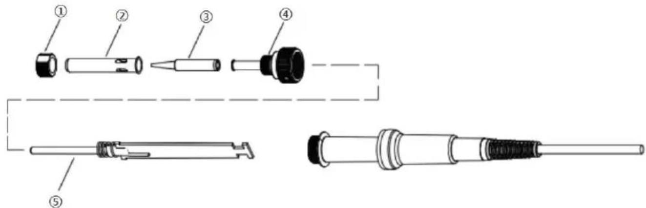
Replacement for Heating Body of Soldering Station
- The heating body of soldering station can be replaced only after unplugged disconnected from the power supply.
- As shown in the figure below, after unscrewing the nut ① , remove the steel jacket ② and soldering iron tip ③, then unscrew the fixing base ④ and de-solder the heating body ⑤ .
• Install the handles according to the reverse procedure of dismantling.
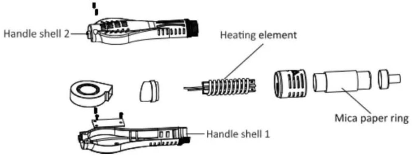
Replacement for Heating Body of Hot Air Rework Station
- The heating element can be replaced when it is cool and the power wire disconnected
- As shown in the figure, loosen two fixed screws on the handle.
-
Screw out the handle shell 1 and then take out the handle shell 2.
-
Remove the fan gently and then take out the fixing screws of terminal block
- Turn over the terminal block, disconnect the connecting wire of heating ele on the terminal block, and pay attention to the position of its connecting wire
- Take out the heating element and the mica paper ring for wrapping the h element from the steel pipe and don't break the earth wire on the steel pipe
- Wrap the new heating element with mica paper ring, insert it into the steel and the heating element should be installed in place.
- Connect the connecting wires of heating element according to the original position.
• Install the handles according to the reverse procedure of dismantling.
WARRANTY TERMS
- We offer a one-year limited warranty for this machine (excluding consumable such as soldering tips and heating elements).
- The warranty covers materials and manufacturing defects from factory shipr collection date and includes both replacement parts and labor.
- The warranty becomes void if the damage is caused by improper use or equipment has been altered or repaired by unauthorized personnel.
MAINTENANCE
In order to make this product durable, please maintain it regularly. The lifespan of this product depends on the used temperature, quality of solder wire and soldering paste, frequency of use etc. Please repair and maintain it according to specific use conditions.
| Warning |
| Please pay close attention when the soldering station is in use at h temperature, turn off the power and unplug the power cord after us |
Soldering iron tip maintenance
- Set the temperature to 250 °C (480 °F).
- After the temperature is stable, clean the soldering iron tip with a brass and check its condition.
- If black oxide is attached to it, please apply new solder (including flux) a it repeatedly with a brass wool until it's clean, then apply some new solder.
- If the soldering iron tip has been deformed, perforated or worn out, please replace it with a new one.
Description of Common Signs
Thank you for purchasing the product, and before using it, please read this manual carefully and pay attention to the warnings and precautions mentioned where in.
 | Warn you to prevent possible electric shock. |
 | Warn you to prevent possible personal injury. |
Requirements for Users
Users should possess the basic knowledge of life and basic knowledge about electrical operations before using this product. The underage should use this product under the guidance of professionals or their guardian.
[Note]: To avoid damaging the machine and maintain the safety of wo environment, please read this instruction carefully before using and kee properly for future reference.
900M-T SERIES SOLDERING TIPS (AM877D+)
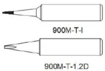
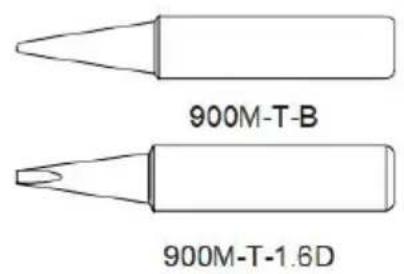
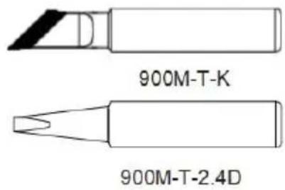
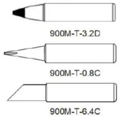
(More soldering tips information please contact us)
FCC Information
CAUTION: Changes or modifications not expressly approved by the party responsible for compliance could void the user's authority to operate the equipment!
This device complies with Part 15 of the FCC Rules. Operation is subject to following two conditions:
1) This product may cause harmful interference.
2) This product must accept any interference received, including interference that may cause undesired operation.
WARNING: Changes or modifications to this product not expressly approved by the party.responsible for compliance could void the user's authority to operate product.
Note: This product has been tested and found to comply with the limits for Class B digital device pursuant to Part 15 of the FCC Rules, These limits are designed to provide reasonable protection against harmful interference in a residential installation.
This product generates, uses and can radiate radio frequency energy, and if installed and used in accordance with the instructions, may cause harmful interference to radio communications. However, there is no guarantee that interference will not occur in a particular installation. If this product does cause harmful interference to radio or television reception, which can be determined by turning the product off and on, the user is encouraged to try to correct the interference by one or more of the following measures.
- Reorient or relocate the receiving antenna.
- Increase the distance between the product and receiver.
- Connect the product to an outlet on a circuit different from that to which receiver is connected.
- Consult the dealer or an experienced radio/TV technician for assistance
CORRECT DISPOSAL
natural_image
Symbol of a trash bin crossed with diagonal lines, no text or numbers presentThis product is subject to the provision of european Directive 2012/19/EU. The symbol showing a wheelie bin crossed through indicates that the product requires separate refuse collection in the European Union. This applies to the product and all accessories marked with this symbol. Products marked as such may not be
discarded with normal domestic waste, but must be taken to a collection point recycling electrical and electronic devices.
Manufacturer: Shanghaimuxinmuyeyouxiangongsi
Address: Shuangchenglu 803nong11hao1602A-1609shi, baoshanqu, shanghai 200000 CN.
Imported to AUS: SIHAO PTY LTD. 1 ROKEVA STREETEASTWOOD NSW 2122 Australia
Imported to USA: Sanven Technology Ltd. Suite 250, 9166 Anaheim Place, Rancho Cucamonga, CA 91730
| UK | REP |
YH CONSULTING LIMITED. C/O YH Consulting Limited Office 147, Centurion House, London Road, Staines-upon-Thames, Surrey, TW18 4AX
| EC | REP |
Technical Support and E-Warranty Certificate
www.vevor.com/support
VEVOR®
TOUGH TOOLS, HALF PRICE
natural_image
Line drawing of an electrical testing device with cables, switches, and control panel (no text or symbols)BESOIN D'AIDE? CONTACTEZ-NOUS!
natural_image
Illustration of an electrical testing device with hoses, control panel, and speaker (no text or symbols)CARACTÉRISTIQUES DU PRODUIT
CONDITIONS DE GARANTIE
(More soldering tips information please contact us)
Informations de la FCC
natural_image
Symbol of a trash bin with crossed lines indicating no waste or discharge, and a solid black rectangle below (no text or labels)YH CONSULTING LIMITED. C/O YH Consulting Limited Bureau 147, Centurion House, London Road, Staines-upon-Thames, Surrey, TW18 4AX
| REPRÉSENTANT | DE LA CE |
E-CrossStu GmbH
Mainzer Landstr.69,
natural_image
Line drawing of an electrical testing device with cables, switches, and a control panel (no text or symbols)natural_image
Line drawing of an electrical testing device with hoses, control panel, and speaker (no text or symbols)GARANTIEBEDINGUNGEN
(More soldering tips information please contact us)
FCC-Informationen
natural_image
Symbol of a trash bin with crossed lines indicating no waste or discharge, and a solid black rectangle below (no text or labels)YH CONSULTING LIMITED. C/O YH Consulting Limited Office 147, Centurion House, London Road, Staines-upon-Thames, Surrey, TW18 4AX
www.vevor.com/support
VEVOR®
TOUGH TOOLS, HALF PRICE
natural_image
Line drawing of an electrical testing device with cables, switches, and control panel (no text or symbols)natural_image
Illustration of an electrical testing device with hoses, control panel, and speaker (no text or symbols)SICUREZZA E PRECAUZIONI
TERMINI DI GARANZIA
(More soldering tips information please contact us)
Informazioni FCC
natural_image
Symbol of a trash bin with crossed lines indicating no waste or discharge, and a solid black rectangle below (no text or labels)Importato in AUS: SIHAO PTY LTD. 1 ROKEVA STREETEASTWOOD NSW 2122 Australia
Importato negli USA: Sanven Technology Ltd. Suite 250, 9166 Anaheim Place, Rancho Cucamonga, CA 91730
YH CONSULTING LIMITED. C/O YH Consulting Limited Ufficio 147, Centurion House, London Road, Staines-upon-Thames, Surrey, TW18 4AX
elettronica www.vevor.com/support
VEVOR®
TOUGH TOOLS, HALF PRICE
natural_image
Line drawing of an electrical testing device with cables, switches, and a control panel (no text or symbols)natural_image
Illustration of a mechanical testing device with hoses and control panel (no text or symbols)SEGURIDAD Y PRECAUCIONES
TÉRMINOS DE GARANTÍA
(More soldering tips information please contact us)
natural_image
Symbol of a trash bin with crossed lines indicating no waste or discharge, and a solid black rectangle below (no text or labels)natural_image
Line drawing of an electrical testing device with cables, switches, and a control panel (no text or symbols)POTRZEBUJESZ POMOCY? SKONTAKTUJ SIĘ Z NAMI!
natural_image
Line drawing of an electrical testing device with hoses and control panel (no text or symbols)BEZPIECZEŃSTWO I ŚRODKI OSTROŻNOŚCI
WARUNKI GWARANCJI
(More soldering tips information please contact us)
Informacje FCC
natural_image
Symbol of a trash bin with crossed lines indicating no waste or discharge, and a solid black rectangle below (no text or labels)YH CONSULTING LIMITED. C/O YH Consulting Limited Biuro 147, Centurion House, London Road, Staines-upon-Thames, Surrey, TW18 4AX
| Przedstaw ciel UE |
E-CrossStu GmbH
Mainzer Landstr.69,
60329 Frankfurt nad Menem.
VEVOR®
TOUGH TOOLS, HALF PRICE
natural_image
Line drawing of an electrical testing device with cables, switches, and a control panel (no text or symbols)HULP NODIG? NEEM CONTACT MET ONS OP!
Soldeerbout handvat: 1st
natural_image
Line drawing of an electrical testing device with hoses, control panel, and base mount (no text or symbols)GARANTIEVOORWAARDEN
(More soldering tips information please contact us)
FCC-informatie
natural_image
Symbol of a trash bin with crossed lines indicating no waste or discharge, and a solid black rectangle below (no text or labels)YH CONSULTING LIMITED. C/O YH Consulting Limited Kantoor 147, Centurion House, London Road, Staines-upon-Thames, Surrey, TW18 4AX
E-CrossStu GmbH
Mainzer Landstr.69,
60329 Frankfurt am Main.
VEVOR®
TOUGH TOOLS, HALF PRICE
garantiecertificaat www.vevor.com/support
VEVOR®
TOUGH TOOLS, HALF PRICE
natural_image
Line drawing of an electrical testing setup with a control panel, coiled cables, and a device (no text or symbols visible)BEHÖVER HJÄLP? KONTAKTA OSS!
natural_image
Line drawing of an electrical testing device with hoses, control panel, and speaker (no text or symbols)SÄKERHET OCH FÖRSIKTIGHETSÅTGÄRDER
GARANTIVILLKOR
(More soldering tips information please contact us)
FCC-information
natural_image
Symbol of a trash bin with crossed lines indicating no waste or discharge, and a solid black rectangle below (no text or labels)YH CONSULTING LIMITED. C/O YH Consulting Limited Office 147, Centurion House, London Road, Staines-upon-Thames, Surrey, TW18 4AX
| EC | REP |
E-CrossStu GmbH
Mainzer Landstr.69,
60329 Frankfurt am Main.
VEVOR®
TOUGH TOOLS, HALF PRICE
www.vevor.com/support


