
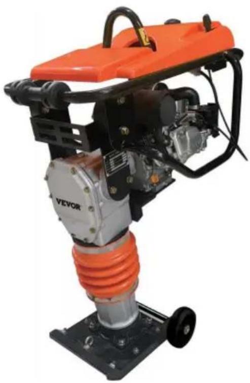
CNCJ-80K-1 - Vibratory plate Vevor - Free user manual and instructions
Find the device manual for free CNCJ-80K-1 Vevor in PDF.

| Product type | Vibratory plate (rammer compactor) |
| Brand | Vevor |
| Model | CNCJ-80K-1 |
| Engine | 6.5 HP (4.1 kW) |
| Plate dimensions | 335 × 280 × 35 mm |
| Maximum jump stroke | 65 mm |
| Strike frequency | 630-680 strokes/min |
| Fuel tank capacity | 2.8 L |
| Engine oil capacity | 0.4-0.6 L (SAE 10W-30) |
| Oil bath capacity | 1 L (Mobil ISO VG46) |
| Fuel type | Unleaded gasoline (octane rating ≥86) |
| Ignition type | Transistorized magneto ignition |
| Starting method | Recoil starter (pull cord) |
| Lubrication system | Oil bath for striking mechanism |
| Weight (approx.) | Approx. 70 kg |
Frequently Asked Questions - CNCJ-80K-1 Vevor
User questions about CNCJ-80K-1 Vevor
0 question about this device. Answer the ones you know or ask your own.
Ask a new question about this device
Download the instructions for your Vibratory plate in PDF format for free! Find your manual CNCJ-80K-1 - Vevor and take your electronic device back in hand. On this page are published all the documents necessary for the use of your device. CNCJ-80K-1 by Vevor.
USER MANUAL CNCJ-80K-1 Vevor
Technical Support and E-Warranty Certificate www.vevor.com/support
MODEL:CNCJ-80K-1/CNCJ-80K
We continue to be committed to provide you tools with competitive price. "Save Half", "Half Price" or any other similar expressions used by us only represents an estimate of savings you might benefit from buying certain tools with us compared to the major top brands and does not necessarily mean to co all categories of tools offered by us. You are kindly reminded to verify carefully when you are placing an order with us if you are actually Saving Half in comparison with the top major brands.
VEVOR®
TOUGH TOOLS, HALF PRICE
Jumping jack compacto
Model:CNCJ-80K-1/CNCJ-80K
natural_image
Orange VEVOR push tool with mechanical components and base mount (no visible text or symbols)NEED HELP? CONTACT US!
Have product questions? Need technical support? Please feel free to contact us:
Technical Support and E-Warranty Certificate www.vevor.com/support
This is the original instruction, please read all manual instructions care before operating. VEVOR reserves a clear interpretation of our user manual. The appearance of the product shall be subject to the product received. Please forgive us that we won't inform you again if there are technology or software updates on our product.
TABLE OF CONTENTS
TABLE OF CONTENTS 2
Product Parameter....3
SAFETY&ALERT SYMBOLS....4
I. INTRODUCTION....4
II.SAFETY&ALERT SYMBOLS....5
2.1 SAFETYSYMBOLS....5
2.2 HAZARDS SYMBOLS....6
2.3 GENERAL SAFETY......8
2.4 TRANSPORTING....10
2.5 MAINTENANCE 11
2.6 EMERGENCIES....11
III. GENERAL INFORMATION......11
3.1 DEFINITION....11
3.2 CONSTRUCTION....12
3.3 CONTROLS....12
3.4 BASIC ENGINE....13
IV. OPERATION 14
4.1 CHECK SPRING CYLINDER OIL BATH....15
4.2 CHECK ENGINE 15
4.3 INSPECTION 16
4.4 START 16
4.5 STOP ENGINE 19
V.MAINTENANCE 20
VI. TROUBLESHOOTING....22
6.1 ENGINE TROUBLESHOOTING 22
6.2 RAMMER TROUBLESHOOTING 24
VII. REPLACEMENT PARTS LIST 24
7.1 GUIDE CYLINDER AND FOOT ASSY .....24
7.2 CRANKCASE AND ENGINE ASSY 28
7.3 TANK AND HANDLE ASSY 30
PARAMETER LIST
| Model | CNCJ-80K-1 | CNCJ-80K |
| Engine horsepower | 6.5HP | 6.5HP |
| Max Jumping Stroke | 65mm | 65mm |
| Number of shocks per minut | 630-680 | 630-680 |
| Number of jumping springs | 1 | 4 |
| Transport wheel outer diameter | ∅137 | ∅137 |
| Bottom plate size | 335*280*35mm | 340*280*40mm |
| gasoline capacity | 2.8L | 2.8L |
| Oil capacity | 0.4-0.6L | 0.4-0.6L |
Accessories instructions
When you receive our package, please open the carton carefully, check accessories, and note that our products should be placed upward; The box includes a main engine with a holder, a pair of casters, a sleeve with an axle, two strips, a product manual and an engine ma Frame and the metal plate of the base before removing the main en
SAFETY&ALERT SYMBOLS

WARNING
To reduce the risk of injury, all operators and maintenance personnel read and understand these instructions before operating, changing accessories, or performing maintenance on power equipment. All possible situations cannot be covered in these instructions. Care must be exercised by everyone using, maintaining or working near this equipment.

CAUTION

NO OIL IN ENGINE
Fill the engine with oil to the correct level before starting the engine.
Thank you for your selection of our equipment.
We have taken care in the design, manufacture and testing of this p Should service or spare parts be required, prompt and efficient service available from our branches.
General Safety instructions for the Operation of Power Equipment. Our factory's goal is to produce power equipment that helps the operator safely and efficiently. The most important safety device for this or any is the operator. Care and good judgment are the best protection again injury. All possible hazards cannot be covered here, but we have tried highlight some of the important items, individuals should look for and Caution, Warning and Danger signs placed on equipment, and displayed the workplace. Operators should read and follow safety instructions packed with each product.
Learn how each machine works. Even if you have previously used si machines, carefully check out each machine before you use it .Get th “feel” of it and know its capabilities, limitations, potential hazards, how operates, and how it stops. We has no duty if person don’t operate instruction said.
II.SAFETY&ALERT SYMBOLS
FOR YOUR SAFETY AND THE SAFETY OF OT
Safety precautions should be followed all the time operating this equipment. Failure to read and und the Safety Messages and Operating Instructions c result in injury to yourself and others.

natural_image
Silhouette of a person using a computer (no text or symbols)
NOTE
This Operating Instructions has been developed to provide complete instructions for the safe and efficient operation of the Tamping Ramme. Refer to the engine manufactures instructions for data relative to its operation.
Before using this rammer, ensure that the operating individual has read and understood all instructions in this manual.
2.1 SAFETY SYMBOLS
The three (3) Safety Messages shown below will inform you about po hazards that could injure you or others. The three Safety Messages specifically address the level of exposure to the operator, and are preceded by one of three words: DANGER, WARNING and CAUTION.

DANGER
You WILL be KILLED or SERIOUSLY INJURED if you DO NOT follow these directions.

WARNING
You CAN be KILLED or SERIOUSLY INJURED if you DO NOT follow directions.

CAUTION
You CAN be INJURED if you DO NOT follow these directions.
2.2 HAZARDS SYMBOLS
Potential hazards associated with the operation of a Tamping Rammer be referenced with Hazard Symbols which appear throughout this man and will be referenced in conjunction with Safety Message Alert Symb
| WARNINGLethal Exhaust Gas HazardsEngine Exhaust gases contain poisonous carbon monoxide. This gas is colorless and odorless, and cause death if inhaled. NEVER operate this equipn a confined area or enclosed structure that does no provide ample free flow air. |  |
| WARNINGExplosive Fuel HazardsGasoline is extremely flammable, and its vapors ca cause an explosion if ignited.DO NOT start the en near spilled fuel or combustible fluids. DO NOT fill tank while the engine is running or hot. DO NOT tank, since spilled fuel could ignite if it comes into with hot engine parts or sparks from the ignition $ Store fuel in approved containers, in well-ventilated and be away from sparks and flames. |  |
| WARNINGBurn HazardsEngine components can generate extreme heat. To prevent burns, DO NOT touch these areas while the engine is running or immediately after operations. I operate the engine with heat shields or heat guard removed. |  |
| WARNINGRespiratory HazardsALWAYS wear approved respiratory protection when required. |  |
| CAUTION Rotating Parts Hazards NEVER operate equipment with covers, or guards removed. Keep fingers, hands, hair and clothing av from all moving parts to prevent injury. | 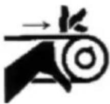 |
| CAUTION Accidental Starting Hazards ALWAYS place the ON/OFF switch in the OFF po when the rammer is not in use. |  |
| CAUTION Eye and Hearing Hazards ALWAYS wear approved eye and hearing protection |  |
| CAUTION Equipment Damage Hazards Other important messages are provided throughout manual to help prevent damage to your light towe property, or the surrounding environment. |

DANGER Refueling Hazard

DANGER Read this manual
Failure to follow instructions in this manual may lead to serious injury even death! This equipment is to be operated by trained and qualified personnel only! This equipment is for industrial use only.
2.3 GENERAL SAFETY
DO NOT operate or service this equipment before reading this entire manual.

natural_image
Silhouette of a person reading a book (no text or symbols visible)This equipment should not be operated by persons under 18 years o NEVER operate this equipment without proper protective clothing, shatterproof glasses, steel-toed boots and other protective devices required by the job.

natural_image
Five black circular icons representing different workplace safety symbols: boot, helmet, suit, helmet with eyes, and glove (no text or labels)NEVER operate this equipment when not feeling well due to fatigue, or taking medicine.
NEVER operate this equipment under the influence of drugs or alcohol

ALWAYS wear proper respiratory (mask), hearing and eye protection equipment when operating the rammer.
Whenever necessary, replace nameplate, operation and safety decals when they become difficult read.
Manufacturer does not assume responsibility for any accident due to equipment modifications.
NEVER use accessories or attachments, which are not recommended this equipment.
Damage to the equipment and/or injury to user may result.
NEVER touch the hot exhaust manifold, muffler or cylinder. Allow these parts to cool before
servicing engine or rammer.

High Temperatures – Allow the engine to cool before adding fuel or performing service and maintenance functions. Contact with hot components can cause serious burns.
The engine section of this rammer requires an adequate free flow of cooling air.
NEVER
operate the rammer in any enclosed or narrow area where free flow air is restricted it
will cause serious damage to the rammer or engine and may cause to people.
Remember the rammer's engine gives off DEADLY carbon monoxide g

ALWAYS refuel in a well-ventilated area, away from sparks and open flames.
ALWAYS use extreme caution when working with flammable liquids. W refueling, stop the engine and allow it cool.
NEVER operate the rammer in an explosive atmosphere or near combustible materials. An explosion or fire could result causing severe bodily harm or even death.
DO NOT smoke around or near the machine. Fire or explosion could from fuel vapors, or if fuel is spilled on a hot engine.
Topping-off to filter port is dangerous, as it tends to spill fuel.
Stop the engine when leaving the rammer unattended.
Maintain this equipment in a safe operating condition at all times.
ALWAYS stop the engine before servicing, adding fuel and oil.
NEVER run engine without air filter. Severe engine may occur.
ALWAYS service air cleaner frequently to prevent carburetor malfunction
ALWAYS check the machine for loosened threads or bolts before sta
ALWAYS be sure the operator is familiar with proper safety precaution and operations techniques before using rammer.
ALWAYS store equipment properly when it is not being used. Equipm should be stored in a clean, dry location out of the reach of children
DO NOT operate this equipment unless all guards and safety devices attached and in place.
CAUTION must be exercised while servicing this equipment.
Keep all inexperienced and unauthorized people away from the equipment at all times.
Unauthorized equipment modifications will void all warranties.
Test the engine ON/OFF switch before operating. The purpose of this switch is to shut down the engine of the rammer.
Refer to the Engine User's Manual for engine technical questions or information
recommended for the equipment.
2.4 TRANSPORTING
ALWAYS shut down engine before transporting.
Tighten fuel tank cap securely and close fuel cock to prevent fuel from spilling.
Drain fuel when transporting rammer over long distances or bad roads. When placing the rammer inside a truck-bed for transport, always tie with the rammer.
2.5 MAINTENANCE
NEVER lubricate components or attempt service on a running rammer. ALWAYS allow the rammer a proper amount of time to cool before servicing.
Keep the rammer in proper running condition.
Fix damage to the rammer immediately and always replace broken pa Dispose of hazardous waste properly. Examples of potentially hazardous waste are used motor oil, fuel and fuel filters.
DO NOT use wooden or plastic containers to dispose of hazardous v
2.6 EMERGENCIES
ALWAYS know the location of the nearest fire extinguisher and first

In emergencies always know the location of the nearest phone or keep phone on the job site.
Also know the phone numbers of the nearest ambulance, doctor and department. This
information will be invaluable in the case of an emergency.

natural_image
Four black-and-white icons representing mobile phone, a bus, a police officer, and a fire department (no text or symbols)III. GENERAL INFORMATION
3.1 DEFINITION
The tamping rammer is a powerful compacting tool capable of applying tremendous force in consecutive impacts to a soil surface. Its application include soil compacting for road, embankments and reservoirs as well backfilling for gas pipelines, water pipelines and cable installation work Circular motion is converted to create impact force. The tamping ramr develops a powerful compacting force at the foot of the rammer. To maintain optimum performance, proper operation and service are essential.
3.2 CONSTRUCTION
The tamping rammer is equipped with an air cooled, four-cycle gasolir engine.
Transmission of the power takes place by increasing the engine speed engage the centrifugal clutch.
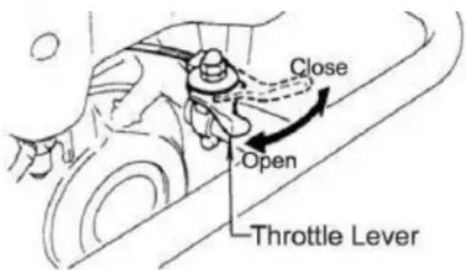
3.3 CONTROLS
Before starting the tamping rammer, identify and understand the function the controls.
Fig1
1 shows the location of the controls and components for the tamping rammer. The
function of each control is described below:
- Throttle Lever – Controls engine speed and the tamping action of the rammer.
- Engine Stop Switch –Controls the starting and stopping of the eng Switch must be in the “ON” position when starting the engine.
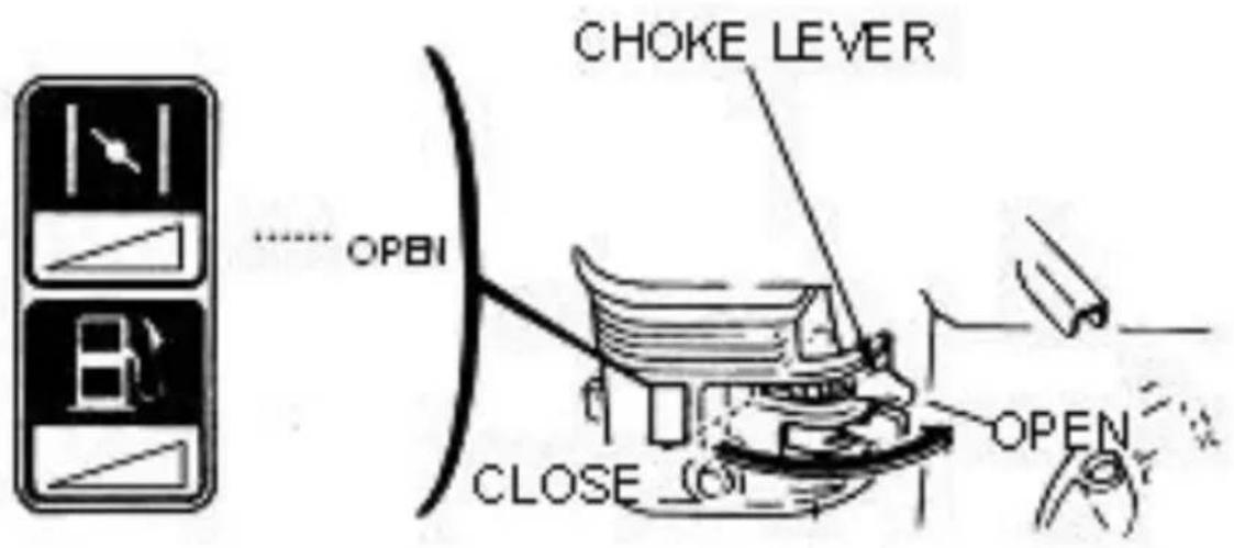
- Choke Lever – Used when starting the engine. Normally used in weather conditions. In cold weather turn the choke lever to the fully position, in warm weather set choke lever half way or completely open
- Fuel Shut-Off Valve – Supplies fuel from the fuel tank to the eng begin fuel flow move the fuel shut-off valve downward.
- Pre-Cleaner – Pre-cleans (first stage) dirt and other debris from er the engine.
- Foot – Laminated wood with tempered steel plate for superior shock absorption.
- Oil Level Sight Glass – Indicates the level of oil in the oil bath
- Recoil Starting Handle – Used when starting the engine. Pull start handle sharply and quickly, then return starter handle to starter case releasing.
- Fuel Tank/Cap – Poly fuel tank to avoid rust and corrosion, reme cap to add gasoline.
- Engine Air Cleaner – Prevents dirt (second stage) and other debris from entering the engine.
- Bellows – Reservoir for oil bath.
- Handle - To operate rammer, grip handle assembly firmly on bot sided.
- Muffler - Used to reduce noise and emissions.
- Spark Plug – Provides spark to the ignition system, replace with manufacturers recommended type spark plug.
- Nameplate – Displays information regarding the rammer.
3.4 BASIC ENGINE
Fig 1A
The engine (Fig 1A) must be checked for proper lubrication and filled fuel prior to operation. Refer to the Engine User's Manual for instruct
- Secondary Air Cleaner – Prevents dirt and other debris from enter the fuel system.
Remove wing-nut on top of air filter canister to gain access to filter element. - Choke Lever – Used when starting the engine. Normally used in c weather conditions. In cold weather turn the choke lever to the fully position, in warm weather set choke lever half way or completely open
- Spark Plug – Provides spark to the ignition system. Set spark plug to 0.6–0.7 mm (0.024–0.028 inch). Clean spark plug once a week.
- Muffler - Used to reduce noise and emissions.

WARNING

Engine components can generate extreme heat. To prevent burns, DO NOT touch these areas while the engine is running or immediately at operating. NEVER operate the engine with the muffler removed.
- Recoil Starter (pull rope) – Manuel-starting method. Pull the starter until resistance is felt, then pull briskly and smoothly.
- Engine ON/OFF Switch – Controls the starting and stopping of the engine. Switch must be in the “ON” position when starting the engine

NOTE
Operate the engine without an air filter, with a damaged air filter, or in need of replacement will allow dirt to enter the engine, causing ra engine wear.
IV. OPERATION
This section is intended to assist the operator with the initial start-up Tamping Rammer.
It's extremely important that this section should be read carefully before attempting to operate the rammer.
DO NOT use your rammer until this section is thoroughly understood.

CAUTION
Read Manual
Failure to understand the operation of the Tamping Rammer could res severe damage to the trowel or personal injury
4.1 CHECK SPRING CYLINDER OIL BATH
This unit uses an oil bath lubrication system. Perform the following:
- Check the oil level through the oil level sight glass (Figure 2) at tl of the tamper foot.
Fig 2
- If oil is not visible, add Mobil ISO VG46 or other oil with same st into the oil fill plug opening (Fig 2). The bath contains approximately cc..

NOTE
The oil level should be kept at the half way point of the sight glass
4.2 CHECK ENGINE
- Fill the fuel tank (Fig 3) with unleaded gasoline. At the same time the engine oil and make it a habit to replenish it often.
Fig 3 Fig 4
- Low levels of oil may result in engine seizure due to high levels of consumption during operations.
- Check the engine oil level (Fig 4) and if the engine oil level is I should be refilled. Use the proper motor oil as suggested in the Tab below.
| Season or Temperature | Grade of motor oil(higher than MS class) |
| Spring, Summer or Autumn+ 120° F to +15° F | SAE 30 |
| Winter+ 40° F to +15° F | SAE 30 |
| Below +15° F | SAE 10w-30 |
4.3 INSPECTION
- Check all nuts, bolts fasteners for tightness. Retighten as necessary
- Clean any dirt from the recoil starter and foot pedestal. Wipe the unit clean before operating.
- Replace any missing or damage Safety Operations decals.
- Adjust height of handle. Adjust handle by loosening nuts and movi handle to suit operation. Retighten nuts.
4.4 START
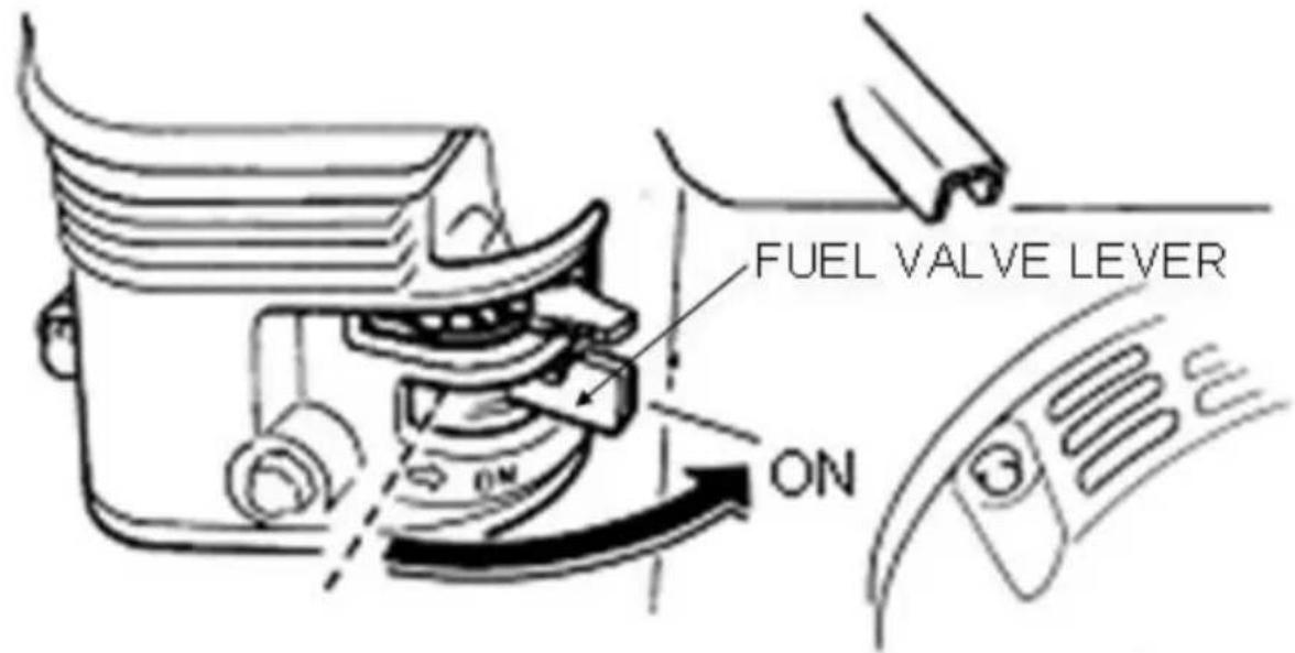
- Open the fuel shut-off valve by moving the fuel cock lever to the position (Fig 5) then set the engine start/stop switch (Fig 5) to the S position.
Fig 5
- Set the engine ON/OFF switch (Fig 6) to the ON position (start)

Fig 6
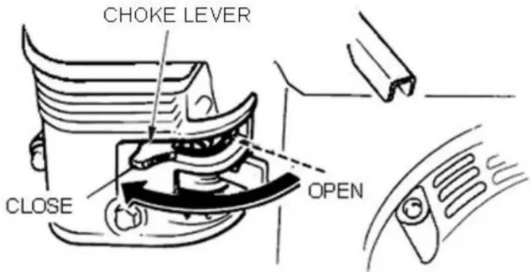
- Close the choke lever (Fig 7) and move the throttle lever to the Open position. Turning the choke lever 90 degrees clockwise closes the choke. In cold weather, start the unit with choke fully closed. In warr weather or when the engine is warm, the unit can be started with c halfway or completely open.
Fig 7
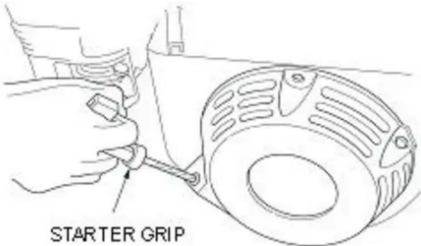
- Grip the recoil starter (Fig 8) handle and pull it until you feel a resistance. Then pull sharply and quickly. Return the recoil starter har to the starter case before releasing.
Fig 8
- If engine fails to start, move the choke lever (Fig 7) to the half position to avoid flooding.
- Repeat steps 1 to 4.
- If the engine does not start after repeated attempts, check the spot for excess fuel.
Clean and replace the spark plug as needed.
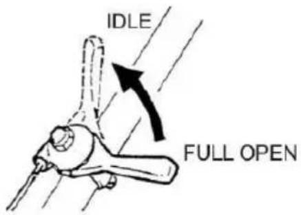
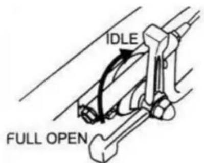
- To start the tamping rammer action, move the throttle lever (Fig 9) quickly from IDLE (close) to the FULL OPEN position. DO NOT move throttle lever slowly as this may cause damage to the clutch or spring. Please be noted that for NEW TYPE throttle lever, get O-ring from ring and accessories bag and fix in the throttle lever as Fig 10.
OLD TYPE
NEW TYPE
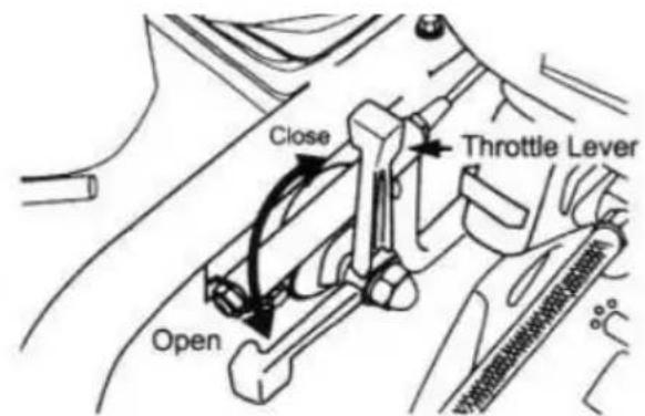
Fig 9

natural_image
Close-up of a hand holding a mechanical component with a central bolt (no visible text or symbols)Fig 10

CAUTION
- Make sure that the throttle lever is moved to the FULL OPEN po Operating the rammer at less than full speeds can result in damage clutch springs or foot.
- The Tamping rammer is designed to run at 4.000 rpm. At optimum the foot hits at the rate of 680 impacts per minute. Increasing throttle past factory set rpm does not increase impacts and may damage uni rammer is designed to advance while tamping.
For faster advance, pull back slightly on the handle so that rear of contacts soil first.
4.5 STOP ENGINE
Normal Shutdown
- Move throttle lever quickly from the FULL OPEN to IDLE position and run the engine for three minutes at low speed. After the engine turn the engine start/stop
switch to the “STOP” position (Figure 6) until engine comes to a cor stop.
OLD TYPE
NEW TYPE
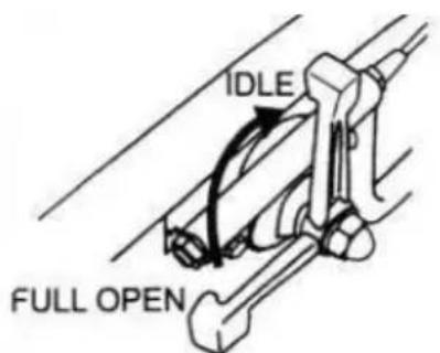
Fig 11
- Close the fuel shut-off valve by moving the fuel cock lever to the CLOSED position. See Figure 5.
Emergency Showdown
Move the throttle lever quickly to the IDLE position, and turn the eng START/STOP switch to the STOP position
V.MAINTENANCE
DAILY
Thoroughly remove dirt and oil from the engine and control area. Cle replace the air cleaner elements as necessary. Check and retighten a fasteners as necessary. Check the spring box and bellows for oil leaf Repair or replace as needed.
WEEKLY
Remove the fuel filter cap and clean the inside of the fuel tank.
Remove or clean the filter at the bottom of the tank.
Remove and clean the spark plug, then adjust the spark gap to 0.02 inch (0.6\~0.7 mm). This unit has electronic ignition, which requires no adjustments.
Clean air cleaner cover.
200 - 300 HOURS
Remove the element from the pre-cleaner (Figure 12) at the top of the crankcase (body side) and clean it with cleaning oil (kerosene).

Figure 12 Optional Pre-Cleaner
Lubricate the top element (yellow) with 2\~5cc of engine oil SAE-30. Lubricate bottom element (gray) with 13\~15cc of engine oil SAE-30 are completely squeeze out the excess oil from the element before installi. The air cleaner (Figure 13) on the engine side will hardly be contam if it is, however after cleaning the element with kerosene, dip it in n consisting of 3 parts of gasoline and 1 part of engine oil. Then tight squeeze outer primary element (sponge) and shake off well the inner secondary element before installing them.
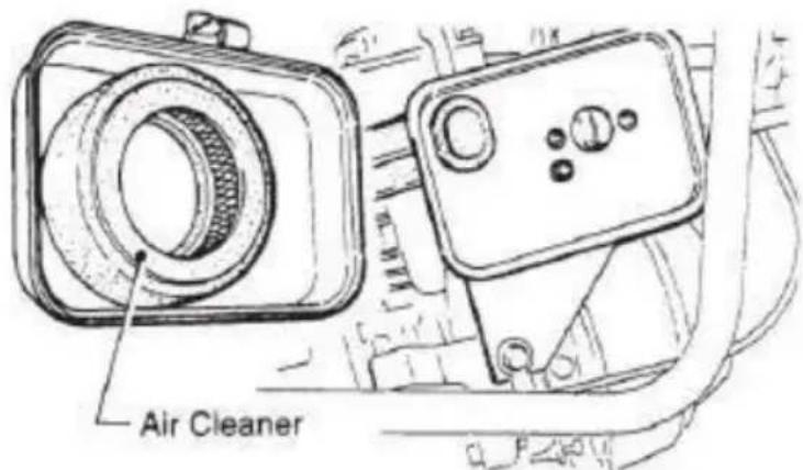
Figure 13 Engine Air Cleaner
200 - 300 HOURS (Oil Bath)
Drain oil reservoir on foot housing (Figure 14). Refill with approximate 1000cc of MOBIL ISO VG-46 or other oil with same standard. Oil sh midway in sight glass. Break in oil should be changed after first 50
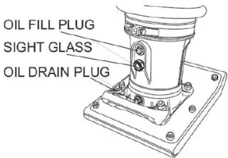
Figure 14 Foot Housing Drain Plug
YEARLY
Check the fuel line and the oil line regularly for damage and to ens there are no leaks.
Replace the oil and fuel lines every two years to maintain the perfor and flexibility lines.
LONG TERM STORAGE
Drain fuel from fuel tank, fuel line and carburetor.
Remove spark plug and pour a few drops of motor oil into cylinder. engine 3 to 4 times so that oil reaches all internal parts.
Clean exterior with a cloth soaked in clean oil.
Store unit covered with plastic sheet in moisture free and dust free I out of direct sunlight.
VI. TROUBLESHOOTING
6.1 ENGINE TROUBLESHOOTING
| SYMPTOM | POSSIBLE PROBLEM | SOLUTION |
| Difficult to start | ||
| Fuel is availab but spark plu will not ignite.(Power available at his tension cable). | Ignition plug being bridge? | Check ignition system |
| Carbon deposit at ignition? | Clean or replace ignition. | |
| Short circuit due to defective insulators? | Replace insulators. | |
| Improper spark gap? | Set spark plug gap the correct gap. | |
| Fuel is availab but spark plu will not ignite (Power NOT available at his tension cable). | Short circuit at stop switch | Check stop switch circuit. Replace stop switch if defective. |
| Ignition coil defective? | Replace ignition coil. | |
| Fuel is availab and spark plu ignites (compression normal). | Muffler clogged with carbon deposits? | Clean or replace muff |
| Fuel in use inadequate (water, dust)? | Flush fuel system ar replace with fresh fuc | |
| Air Cleaner clogged? | Clean or replace ai cleaner. | |
| Fuel is availab and spark plu ignites (compression low). | Defective cylinder head gaske | Tighten cylinder head bolts or replace hea gasket. |
| Cylinder worn? | Replace cylinder. | |
| Spark plug loose? | Tighten spark plug | |
| Operation not satisfactory | ||
| Not enough power available (compression normal, no misfiring). | Air cleaner clogged? | Clean or replace air cleaner. |
| Air in fuel line? | Bleed (remove air) from fuel line. | |
| Fuel level in carburetor float chamber improper? | Adjust carburetor float | |
| Carbon deposits in cylinder? | Clean or replace cylinder. | |
| Not enough power available (compression normal, misfiring). | Ignition coil defective? | Flush fuel system and replace with fresh fuel |
| Ignition plug often shorts? | Clean or replace crankcase. | |
| Fuel in use inadequate (water, dust)? | Clean or replace muff | |
| Engine overheats. | Combustion chamber? | Clean or replace crankcase. |
| Exhaust or muffler clogged with carbon. | Clean or replace muff | |
| Spark plug heat value incorre | Replace spark plug with correct type spark plu | |
| SYMPTOM | POSSIBLE PROBLEM | SOLUTION |
| Rotational speed fluctuates. | Governor adjustment improper | Adjust governor to correct lever. |
| Governor spring defective? | Clean or replace ignition. | |
| Fuel flow erratic? | Check fuel line. | |
| Air taken in through suction | Check suction line. | |
| Recoil starter not working properly. | Dustin rotating part? | Clean recoil starter assembly. |
| Spiral spring failure? | Replace spiral spring | |
6.2 RAMMER TROUBLESHOOTING
| Engine rotates but amplitude not uniform or does n strike. | Operation speed of throttle lever is incorrectly set? | Set throttle lever to correct position. |
| Oil in excess? | Drain excess oil. Br to correct level. | |
| Clutch slips? | Replace or adjust clutch. | |
| Spring Failure? | Replace spiral spring | |
| Speed of engine improper? | Adjust engine speed to correct operating RPM setting. |
VII. REPLACEMENT PARTS LIST
7.1 GUIDE CYLINDER AND FOOT ASSY
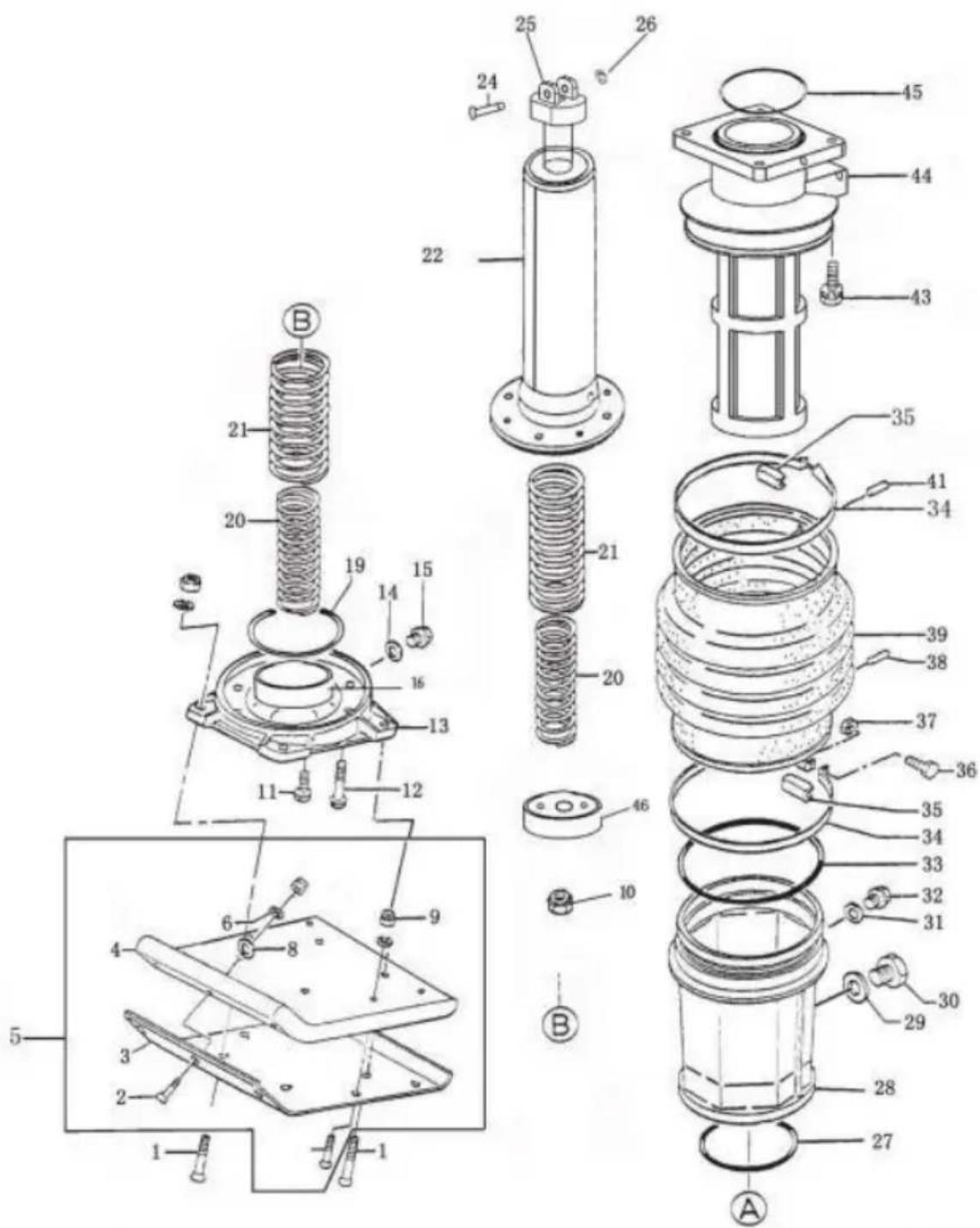
| PART NO | DESCRIPTION | QTY |
| A01 | Sunk head bolt 12*75H( Foot Assy with/ Handle/ with Plastic sleeve) | 4 |
| A01 | Sunk head bolt 12*105H( Foot Assy with/ Handle/with Plastic Al sleeve) | 4 |
| A01 | Sunk head bolt 12*105H( Foot Assy with | 4 |
| A01 | Sunk head bolt 12*105H( Foot Assy with Handle/with Al sleeve) | 4 |
| A02 | Sunk head bolt 12*55 H | 7 |
| A03 | Metal sheet | 1 |
| A04 | Foot 285B-331L | 1 |
| A05 | Foot Assy | 1 |
| A06 | Washer SWφ12 | 11 |
| A08 | Washer SWφ12 | 7 |
| A09 | Nylon nut M12 | 11 |
| A10 | Nut M18, | 1 |
| A11 | Socket head bolt 10*20T | 4 |
| A12 | Socket head bolt 10*35T | 4 |
| A3 | Foot plate | 1 |
| A14 | Packing 1/4(CU) | 1 |
| A15 | Plug M12*1.25 | 1 |
| A19 | O-ring G-90 | 1 |
| A20 | Inner spring ( for engines except Honda G | 2 |
| A20 | Inner spring ( for Honda GX100) | 2 |
| A21 | Out spring | 2 |
| A22 | Spring cylinder | 1 |
| A24 | Pin § 16 | 1 |
| A25 | Piston rod kit | 1 |
| A26 | Stop ring § 15 | 1 |
| A27 | O-ring G-90 | 2 |
| A28 | Protection sleeve (Plastic) | 1 |
| A28 | Protection sleeve(Optional AI) | 1 |
| A29 | Copper packing 17*25.5*1 | 1 |
| A30 | Level gauge, plug type | 1 |
| A31 | Packing 1/4(CU) | 1 |
| A32 | Plug M12*1.25 | 1 |
| A33 | O-ring 160*4 | 1 |
| A34 | Bellows clamp | 2 |
| A35 | Band guide,bellows | 2 |
| A36 | Socket head bolt M6*50 | 2 |
| A37 | Nut M6 | 2 |
| A38 | Dowel pinφ6×8 | 1 |
| A39 | Bellow (Made in China) | 1 |
| A39 | Bellow(Made in Germany, optional) | 1 |
| A41 | Pin 6D-8.5L | |
| A43 | Socket head bolt 10*35T | 4 |
| A44 | Guide cylinder | 1 |
| A45 | O-ring φ110×4 | 1 |
| A46 | piston end | 1 |
7.2 CRANKCASE AND ENGINE ASSY
| PART NO. | DESCRIPTION | QTY |
| B01 | Bolt 6*18H,SW | 9 |
| B02 | Case cover | 1 |
| B03 | O-ring 22.4*2.65 | 1 |
| B04 | Hexagonal bolt 8*20 | 1 |
| B05 | Washer M8 | 1 |
| B06 | Internal circlip φ50 | 1 |
| B07 | Bearing6204 | 1 |
| B08 | Connecting rod | 1 |
| B09 | Gearwheel | 1 |
| B10 | Internal circlip φ62 | 1 |
| B11 | Bearing6207 | 1 |
| B12 | Bearing6305-2Z | 1 |
| B13 | Crank case | 1 |
| B14 | External circlip φ20 | 1 |
| B15 | O-ring 40*2.4 | 1 |
| B16 | Bearing cover | 1 |
| B17 | Key 5*20 | 1 |
| B18 | Pinion( for engines except Honda GX100) | 1 |
| B18 | Pinion( for Honda GX100) | 1 |
| B19 | Bearing6204 | 1 |
| B20 | Bearing6007 | 1 |
| B21 | Oil seal 40*68*8 | 1 |
| B22 | Clutch drum( for engines except Honda GX1 | 1 |
| B22 | Clutch drum(for Honda GX120) | 1 |
| B23 | Washer ∅ 8*7 | 1 |
| B24 | Bolt M 8*25 T | 1 |
| B25 | Washer SW φ10 | 4 |
| B26 | Socket head bolt 10*35 | 4 |
| B27 | Lock washer | 1 |
| B28 | Clutch assy ( depends on engines) | 1 |
| B29 | Woodruff key 4*13 | 1 |
| B30 | Connecting plate, engine( depends on engine | 1 |
| B31 | Engine | 1 |
| B32 | Bottom plate, engine( depends on engines) | 1 |
| B33 | Bolt M10*50 | 2 |
| B34 | Bolt M8*40 | 4 |
| B35 | Washer, SW M8 | 4 |
| B36 | Washer,8.5*22*3 | 4 |
| B37 | Nylon nut M8 | 4 |
| B40 | Throttle cable( depends on engines) | 1 |
| B43 | Throttle lever | 1 |
7.3 TANK AND HANDLE ASSY
| PART NO. | DESCRIPTION | QTY |
| C01 | Handle( depends on engines) | 1 |
| C02 | Roller handle | 1 |
| C03 | Flange bolt 8*25 H | 4 |
| C04 | Flange nut M5 | 4 |
| C05 | Shock absorber | 2 |
| C06--1 | Shock head bolt 10*20 | 4 |
| C06--2 | Tooth locked washer BM10 | 8 |
| C07 | Bolt10*20 T | 4 |
| C08 | Nylon nut M8 | 2 |
| C09 | Washer,φ8*22*3 | 2 |
| C11 | Fuel tank | 1 |
| C12 | Hexagonal bolt 8*40 | 2 |
| C13 | Fueltank cap | 1 |
| C15 | washer,throttle lever | 1 |
| C17 | Fuel cock assy | 1 |
| C18 | Hose band 9.5D | 2 |
| C19 | Hose, fuel | 1 |
| C20 | Hose band 9.5D | 2 |
Manufacturer: Shanghaimuxinmuyeyouxiangongsi
Address: Shuangchenglu 803nong11hao1602A-1609shi, baoshanqu, shanghai 200000 CN.
Imported to AUS: SIHAO PTY LTD. 1 ROKEVA STREETEASTWOOD NSW 2122 Australia
Imported to USA: Sanven Technology Ltd. Suite 250, 9166 Anaheim Place, Rancho Cucamonga, CA 91730
| UK | REP |
YH CONSULTING LIMITED. C/O YH Consultin Limited Office 147, Centurion House, London Road, Staines-upon-Thames, Surrey, TW18 4A>
| EC | REP |
Technical Support and E-Warranty Certificate
www.vevor.com/support
VEVOR®
TOUGH TOOLS, HALF PRICE
MODÈLE : CNCJ-80K-1/CNCJ-80K
natural_image
Orange VEVOR manual tool with mechanical components and base mount (no visible text or symbols)BESOIN D'AIDE? CONTACTEZ-NOUS!
INFORMATIONS GÉNÉRALES....11
3.1 DÉFINITION....11
3.2 CONSTRUCTION....12
3.3 COMMANDES....12
3.4 MOTEUR DE BASE....13
FONCTIONNEMENT 14
4.1 VÉRIFICATION DU BAIN D'HUILE DU CYLINDRE À RESSORT....15
4.2 CONTRÔLE DU MOTEUR 15
4.3 INSPECTION 16
4.4 DÉMARRAGE ....16
4.5 ARRÊT DU MOTEUR 19
.ENTRETIEN ....20
DÉPANNAGE....22
6.1 DÉPANNAGE DU MOTEUR 22
6.2 DÉPANNAGE DU PILONNEUR .....24
LISTE DES PIÈCES DE RECHANGE....24
7.1 ENSEMBLE CYLINDRE DE GUIDAGE ET PIED 24
7.2 ENSEMBLE CARTER ET MOTEUR .....28
7.3 ENSEMBLE RÉSERVOIR ET POIGNÉE ....30
LISTE DES PARAMÈTRES
Fill the engine with oil to the correct level before starting the engine.
natural_image
Silhouette of a lightning bolt striking a flame (no text or symbols)
WARNING
Risques de brûlures
natural_image
Silhouette of a person reading a book (no text or symbols visible)natural_image
Five black circular icons representing different workplace safety symbols: boot, helmet, suit, gear, and glove (no text or labels). INFORMATIONS GÉNÉRALES
3.1 DÉFINITION La
Fig1
Fig. 1A
Fig 3

Fig. 4
Fig. 5
Fig. 7
NOUVEAU TYPE
Fig. 9

natural_image
Close-up of a hand holding a mechanical component with a central hexagonal bolt (no visible text or symbols)Fig. 10

CAUTION
NOUVEAU TYPE

Fig. 11
GUIDE CYLINDER AND FOOT ASSY (A)
Fabricant : Shanghaimuxinmuyeyouxiangongsi Adresse :
Shuangchenglu 803nong11hao1602A-1609shi, baoshanqu, shanghai 200000 CN.
Importé en Australie : SIHAO PTY LTD. 1 ROKEVA STREETEASTWOOD NSW 2122 Australie
YH CONSULTING LIMITED. C/O YH Consulting Limited Bureau 147, Centurion House, London Road, Staines-upon-Thames, Surrey, TW18 4AX
| REPRÉSENTANT DE LA CE |
E-CrossStu GmbH
Mainzer Landstr.69,
MODELL: CNCJ-80K-1/CNCJ-80K
natural_image
Orange VEVOR manual tool with mechanical components and base mount (no visible text or symbols)2.2 GEFAHRENSYMBOLE....6
Fill the engine with oil to the correct level before starting the engine.
natural_image
Silhouette of a person using a computer (no text or symbols)
NOTE
natural_image
Silhouette of a person reading a book (no text or symbols visible)natural_image
Five black circular icons representing different workplace safety symbols: boot, helmet, suit, gear, and glove (no text or labels)ÿ. ALLGEMEINE INFORMATIONEN
3.1 DEFINITION Der
Abb. 1
Abb. 1A
Abb. 3

Abb. 4
Abb. 5
Abb. 7
NEUER TYP

Abb. 9

natural_image
Close-up of a hand holding a mechanical component with a central hexagonal bolt (no visible text or symbols)Abb. 10

CAUTION
NEUER TYP
Abb. 11
Abbildung 13 Motorluftfilter
GUIDE CYLINDER AND FOOT ASSY (A)

Hersteller: Shanghaimuxinmuyeyouxiangongsi Adresse:
Shuangchenglu 803nong11hao1602A-1609shi, baoshanqu, Shanghai 200000 CN.
Nach AUS importiert: SIHAO PTY LTD. 1 ROKEVA STREETEASTWOOD NSW 2122 Australien
Importiert in die USA: Sanven Technology Ltd. Suite 250, 9166 Anaheim Place, Rancho Cucamonga, CA 91730
| UK | REP |
YH CONSULTING LIMITED. C/O YH Consulting Limited Office 147, Centurion House, London Road, Staines-upon-Thames, Surrey, TW18 4AX

www.vevor.com/support
VEVOR®
TOUGH TOOLS, HALF PRICE
MODELLO:CNCJ-80K-1/CNCJ-80K
natural_image
Orange VEVOR manual tool with mechanical components and orange spring (no visible text or symbols)www.vevor.com/support
Fill the engine with oil to the correct level before starting the engine.
natural_image
Silhouette of a person with a lamp and explosion sparks (no text or symbols)
WARNING
Rischi di ustione
natural_image
Silhouette of a person reading a book (no text or symbols visible)natural_image
Five black circular icons representing different workplace safety symbols: boot, helmet, suit, gear, and glove (no text or labels)Figura 1
Figura 1A
Figura 3

Figura 4
Figura 5
Figura 7
NUOVO TIPO

Figura 9

natural_image
Close-up of a hand holding a mechanical component with a central bolt and metallic housing (no visible text or symbols)Figura 10

CAUTION
NUOVO TIPO

Figura 11
GUIDE CYLINDER AND FOOT ASSY (A)

Importato in AUS: SIHAO PTY LTD. 1 ROKEVA STREETEASTWOOD NSW 2122 Australia
Importato negli USA: Sanven Technology Ltd. Suite 250, 9166 Anaheim Place, Rancho Cucamonga, CA 91730
YH CONSULTING LIMITED. C/O YH Consulting Limited Ufficio 147, Centurion House, London Road, Staines- upon-Thames, Surrey, TW18 4AX

elettronica www.vevor.com/support
VEVOR®
TOUGH TOOLS, HALF PRICE
MODELO:CNCJ-80K-1/CNCJ-80K
natural_image
Orange VEVOR manual tool with mechanical components and orange spring (no visible text or symbols)Fill the engine with oil to the correct level before starting the engine.
natural_image
Silhouette of a person using a computer (no text or symbols)
NOTE
natural_image
Silhouette of a person with a large hat and spiky hair, no text or symbols present
WARNING
natural_image
Silhouette of a person reading a book (no text or symbols visible)natural_image
Five black circular icons representing different workplace safety symbols: boot, helmet, suit, gear, and glove (no text or labels)Figura 1
Figura 1A
Figura 3
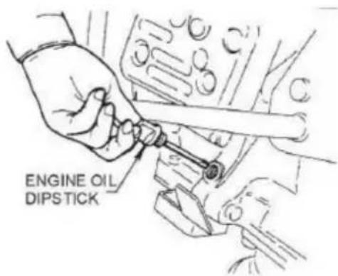
Figura 4
Figura 5
Figura 7
NUEVO TIPO

Figura 9

natural_image
Close-up of a hand holding a mechanical component with a central bolt and metallic housing (no visible text or symbols)Figura 10

CAUTION
NUEVO TIPO

Figura 11
Figura 13 Filtro de aire del motor
200 - 300 HORAS (Baño de aceite)
GUIDE CYLINDER AND FOOT ASSY (A)

Road, Staines-upon-Thames, Surrey, TW18 4AX

E-CrossStu GmbH
Mainzer Landstr.69,
MODEL:CNCJ-80K-1/CNCJ-80K
Modele:CNCJ-80K-1/CNCJ-80K

natural_image
Orange VEVOR manual tool with mechanical components and base mount (no visible text or symbols)POTRZEBUJESZ POMOCY? SKONTAKTUJ SIĘ Z NAMI!
www.vevor.com/support
SYMBOLE BEZPIECZEŃSTWA I ALARMÓW....4
I. WSTEP....4
II.SYMBOLE BEZPIECZEŃSTWA I ALARMÓW....5
2.1 SYMBOLE BEZPIECZEŃSTWA....5
2.2 SYMBOLE ZAGROŻEŃ......6
2.3 OGÓLNE BEZPIECZEŃSTWO....8
2.4 TRANSPORT....10
2.5 KONSERWACJA ....11
2.6 SYTUACJE AWARYJNE....11
III. INFORMACJE OGÓLNE....11
3.1 DEFINICJA....11
3.2 BUDOWA....12
Fill the engine with oil to the correct level before starting the engine.
natural_image
Silhouette of a person using a computer (no text or symbols)
NOTE
natural_image
Silhouette of a person with a flag above a flame (no text or symbols)
WARNING
natural_image
Silhouette of a person reading a book (no text or symbols visible)natural_image
Five black circular icons representing different workplace safety symbols: boot, helmet, suit, gear, and glove (no text or labels)III. INFORMACJE OGÓLNE
3.1 DEFINICJA Ubijak
Rys. 1
Rys. 1A
Rys. 3

Rys. 4
Rys. 5
Ryc. 7
NOWY TYP

Ryc. 9
natural_image
Close-up of a hand holding a mechanical component with a central hexagonal bolt (no visible text or symbols)Ryc. 10

CAUTION
NOWY TYP

Ryc. 11
GUIDE CYLINDER AND FOOT ASSY (A)

Producent: Shanghaimuxinmuyeyouxiangongsi Adres:
Shuangchenglu 803nong11hao1602A-1609shi, baoshanqu, szanghaj 200000 CN.
Importowane do AUS: SIHAO PTY LTD. 1 ROKEVA STREETEASTWOOD NSW 2122 Australia
Importowane do USA: Sanven Technology Ltd. Suite 250, 9166 Anaheim Place, Rancho Cucamonga, CA 91730
| REP WIEL KIEJ BRYTANII |
YH CONSULTING LIMITED. C/O YH Consulting Limited Biuro 147, Centurion House, London Road, Staines-upon-Thames, Surrey, TW18 4AX
| Przedstaw ciel UE |
E-CrossStu GmbH
Mainzer Landstr.69,
60329 Frankfurt nad Menem.
VEVOR®
TOUGH TOOLS, HALF PRICE
MODEL: CNCJ-80K-1/CNCJ-80K
Model:CNCJ-80K-1/CNCJ-80K
natural_image
Orange VEVOR manual tool with mechanical components and base mount (no visible text or symbols)HULP NODIG? NEEM CONTACT MET ONS OP!
www.vevor.com/support
VEILIGHEIDS- EN WAARSCHUWINGSSYMBOLEN....4
ÿ. INLEIDING....4
ÿ.VEILIGHEIDS- EN WAARSCHUWINGSSYMBOLEN....5
2.1 VEILIGHEIDSSYMBOLEN....5
2.2 GEVARENSYMBOLEN....6
2.3 ALGEMENE VEILIGHEID....8
2.4 TRANSPORTEREN....10
2.5 ONDERHOUD ....11
2.6 NOODGEVALLEN....11
ÿ. ALGEMENE INFORMATIE....11
3.1 DEFINITIE....11
3.2 CONSTRUCTIE....12
3.3 CONTROLES....12
3.4 BASISMOTOR....13
ÿ. BEDIENING ....14
4.1 CONTROLEER DE OLIEBAD VAN DE VEERCILINDER....15
4.2 MOTOR CONTROLLEREN ....15
4.3 INSPECTIE ....16
4.4 BEGINNEN 16
4.5 MOTOR STOPPEN 19
ÿ.ONDERHOUD ....20
ÿ. PROBLEEMOPLOSSING....22
6.1 MOTORPROBLEMEN OPLOSSEN 22
6.2 PROBLEEMOPLOSSING VAN RAMMER 24
ÿ. LIJST MET VERVANGENDE ONDERDELEN ....24
7.1 GELEIDECILINDER EN VOETASSEMBLAGE 24
7.2 CARTER- EN MOTORASSEMBLAGE 28
7.3 TANK- EN HANDVATASSEMBLAGE 30
PARAMETERLIJST
| Model | CNCJ-80K-1 | CNCJ-80K |
| Motorvermogen | 6,5 pk | 6,5 pk |
| Maximale sprongslag | 65mm | 65mm |
| Aantal schokken per minuut | 630-680 | 630-680 |
| Aantal springveren | 1 | 4 |
| Transportwiel buitendiameter | ∅137 | ∅137 |
| Bodemplaat maat | 335*280*35mm 340*280*40mm | |
| benzine capaciteit | 2,8L | 2,8L |
| Olie capaciteit | 0,4-0,6L | 0,4-0,6L |
VEILIGHEIDS- EN WAARSCHUWINGSSYMBOLEN

WAARSCHUWING
Fill the engine with oil to the correct level before starting the engine.
ÿ.VEILIGHEIDS- EN WAARSCHUWINGSSYMBOLEN
VOOR UW VEILIGHEID EN DE VEILIGHEID VAN ANDEREN!
natural_image
Silhouette of a person using a computer (no text or symbols)
NOTE
natural_image
Silhouette of a person reading a book (no text or symbols visible)natural_image
Five black circular icons representing different workplace safety symbols: boot, helmet, suit, gear, and glove (no text or labels)Giet of spuit NOOIT water over de motor.
Figuur 1
Figuur 1A
Figuur 3
Figuur 4
Figuur 5
Figuur 7
NIEUW TYPE

Figuur 9
natural_image
Close-up of a hand holding a mechanical component with a central bolt and metallic housing (no visible text or symbols)Figuur 10

CAUTION
NIEUW TYPE
Figuur 11
ÿ. PROBLEEMOPLOSSING
6.1 MOTORPROBLEMEN OPLOSSEN
GUIDE CYLINDER AND FOOT ASSY (A)

Fabrikant: Shanghaimuxinmuyeyouxiangongsi Adres:
Shuangchenglu 803nong11hao1602A-1609shi, baoshanqu, shanghai 200000 CN.
YH CONSULTING LIMITED. C/O YH Consulting Limited Kantoor 147, Centurion House, London Road, Staines- upon-Thames, Surrey, TW18 4AX

MODELL: CNCJ-80K-1/CNCJ-80K
natural_image
Orange VEVOR manual tool with mechanical components and base mount (no visible text or symbols)BEHÖVER HJÄLP? KONTAKTA OSS!
INNEHÅLLSFÖRTECKNING
INNEHÅLLSFÖRTECKNING 2
Produktparameter ....3
SÄKERHETS- OCH VARNINGSSYMBOLER....4
ÿ. INTRODUKTION....4
ÿ.SÄKERHETS- OCH VARNINGSSYMBOLER....5
2.1 SÄKERHETSSYMBOLER....5
2.2 RISKER SYMBOLER....6
2.3 ALLMÄN SÄKERHET....8
2.4 TRANSPORTER....10
2.5 UNDERHÅLL 11
2.6 NÖDSTOPP....11
ÿ. ALLMÄN INFORMATION....11
3.1 DEFINITION....11
3.2 KONSTRUKTION....12
3.3 KONTROLLER....12
3.4 GRUNDMOTOR....13
ÿ. DRIFT ....14
4.1 KONTROLLERA FJÄDERCYLINDEROLJEBAD....15
4.2 KONTROLLERA MOTORN 15
4.3 INSPEKTION 16
4.4 STARTA 16
4.5 STOPPA MOTOR ....19
ÿ.UNDERHÅLL 20
ÿ. FELSÖKNING....22
6.1 FELSÖKNING AV MOTOR ....22
6.2 FELSÖKNING AV RAMMER ....24
ÿ. RESERVDELAR LISTA ......24
7.1 STYRCYLINDER OCH FOTSAMLING 24
7.2 VELVHUS OCH MOTORMONTERING ....28
7.3 TANK OCH HANDTAG 30
PARAMETERLISTA
| Modell | CNCJ-80K-1 | CNCJ-80K |
| Motor hästkrafter | 6,5 hk | 6,5 hk |
| Max Hoppslag | 65 mm | 65 mm |
| Antal stötar per minut | 630-680 | 630-680 |
| Antal hoppfjädrar | 1 | 4 |
| Transporthjulets ytterdiameter | ∅137 | ∅137 |
| Bottenplattans storlek | 335*280*35mm 340*280*40mm | |
| bensinkapacitet | 2,8 L | 2,8 L |
| Oljekapacitet | 0,4-0,6L | 0,4-0,6L |
Fill the engine with oil to the correct level before starting the engine.
natural_image
Silhouette of a person using a computer (no text or symbols)
NOTE
natural_image
Silhouette of a person using a computer (no text or symbols)natural_image
Five black circular icons representing different workplace safety symbols: boot, helmet, suit, gear, and glove (no text or labels)ÿ. ALLMÄN INFORMATION
3.1 DEFINITION
Fig1
Fig 1A

Fig 3
Fig 4
Fig 5
Fig 7
NY TYP

Fig 9

natural_image
Close-up of a hand holding a mechanical component with a central bolt and metallic housing (no visible text or symbols)Fig 10

CAUTION
NY TYP

Fig 11
Figur 13 Motorluftrenare
200 - 300 TIMMAR (oljebad)
GUIDE CYLINDER AND FOOT ASSY (A)

Tillverkare: Shanghaimuxinmuyeyouxiangongsi Adress:
Shuangchenglu 803nong11hao1602A-1609shi, baoshanqu, shanghai 200000 CN.
Importerad till AUS: SIHAO PTY LTD. 1 ROKEVA STREETEASTWOOD NSW 2122 Australien
Importerad till USA: Sanven Technology Ltd. Suite 250, 9166 Anaheim Place, Rancho Cucamonga, CA 91730
| UK | REP |
YH CONSULTING LIMITED. C/O YH Consulting Limited Office 147, Centurion House, London Road, Staines-upon-Thames, Surrey, TW18 4AX
| EC | REP |
www.vevor.com/support
VEVOR®
TOUGH TOOLS, HALF PRICE
Technical Support and E-Warranty Certificate www.vevor.com/support
LC168F-2H Engine
MODEL:LC168F-2H
We continue to be committed to provide you tools with competitive price. "Save Half", "Half Price" or any other similar expressions used by us only represents an estimate of savings you might benefit from buying certain tools with us compared to the major top brands and does not necessarily mean to co all categories of tools offered by us. You are kindly reminded to verify carefully when you are placing an order with us if you are actually Saving Half in comparison with the top major brands.
MODEL:LC168F-2H
natural_image
Technical line drawing of a mechanical pump or motor assembly (no text or symbols)NEED HELP? CONTACT US!
Have product questions? Need technical support? Please feel free to contact us:
Technical Support and E-Warranty Certificate www.vevor.com/support
This is the original instruction, please read all manual instructions care before operating. VEVOR reserves a clear interpretation of our user manual. The appearance of the product shall be subject to the product received. Please forgive us that we won't inform you again if there are technology or software updates on our product.
! DANGER
Keep this owner's manual handy, so you can refer to it at any time. This owner's manual is considered a permanent part of the engine and should remain with the engine if resold.
The information and specifications included in this publication were in effect at the time of approval for printing.
READ THIS OWNER'S MANUAL CAREFULLY. Pay special attention to these symbols and any instructions that follow:
WARNING
Indicates serious injury or death will result if instructions are not follow
! DANGER
A DANGER Indicates a strong possibility that serious injury or deaf could result if instructions are not followed.
CAUTION
A CAUTION Indicates a possibility that minor injury or an result if instructions are not followed.
NOTICE
INDicates that equipment or property damage can result if instructions are not followed.
NOTE: Gives helpful information. If a problem should arise, or if you any questions about your engine, consult your engine dealer.
TABLE OF CONTENTS
| Project | Pagination |
| 1. ENGINE SAFETY | 4 |
| 2. COMPONENTS & CONTROL LOCATIONS | 5 |
| 3. CONTROLS | 5 |
| 4. CHECK BEFORE OPERATION | 8 |
| 5. OPERATION | 9 |
| 6. MAINTENANCE | 15 |
| 7. STORAGE/TRANSPORTING | 27 |
| 8. TROUBLESHOOTING | 32 |
| 9. TECHNICAL & CONSUMER INFORMATION | 33 |
| 10. Specifications | 39 |
| 11. Wiring Diagrams | 40 |
1. ENGINE SAFETY
IMPORTANT SAFETY INFORMATION
Most accidents with engines can be prevented if you follow all instruct in this manual and on the engine. Some of the most common hazard discussed below, along with the best way to protect yourself and other
Owner Responsibilities
- The engines are designed to give safe and dependable service if operated according to instructions. Read and understand this owner's manual before operating the engine. Failure to do so could result in personal injury or equipment damage.
- Know how to stop the engine quickly, and understand the operation controls. Never permit anyone to operate the engine without proper instructions.
- Do not allow children to operate the engine. Keep children and pet from the area of operation.
Refuel With Care
Gasoline is extremely flammable, and gasoline vapor can explode. Ref outdoors, in a well-ventilated area, with the engine stopped. Never sm near gasoline, and keep other flames and sparks away. Always store gasoline in an approved container. If any fuel is spilled, make sure t is dry before starting the engine.
Hot Exhaust
- The muffler becomes very hot during operation and remains hot for while after stopping the engine. Be careful not to touch the muffler v is hot. Let the engine cool before storing it indoors.
• To prevent fire hazards and to provide adequate ventilation for static equipment applications, keep the engine at least 3 feet (1 meter) away from building walls and other equipment during operation. Do not place flammable objects close to the engine.
Carbon Monoxide Hazard
Exhaust gas contains poisonous carbon monoxide. Avoid inhalation of exhaust gas. Never run the engine in a closed garage or confined a Other Equipment
Review the instructions provided with the equipment powered by this engine for any additional safety precautions that should be observed in conjunction with engine startup, shutdown, operation, or protective appa that may
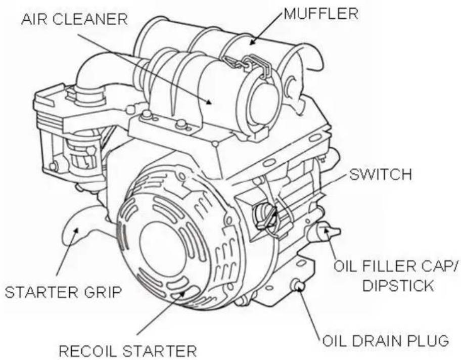
2. COMPONENTS & CONTROL LOCATIONS
3. CONTROLS
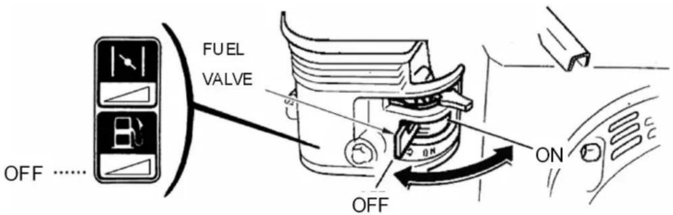
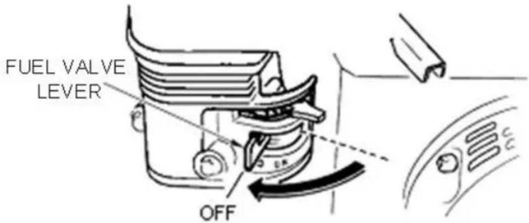
Fuel Valve Lever
The fuel valve opens and closes the passage between the fuel tank the carburetor.
The fuel valve lever must be in the ON position for the engine to r When the engine is not in use, leave the fuel valve lever in the OF position to prevent carburetor flooding and to reduce the possibility of leakage.
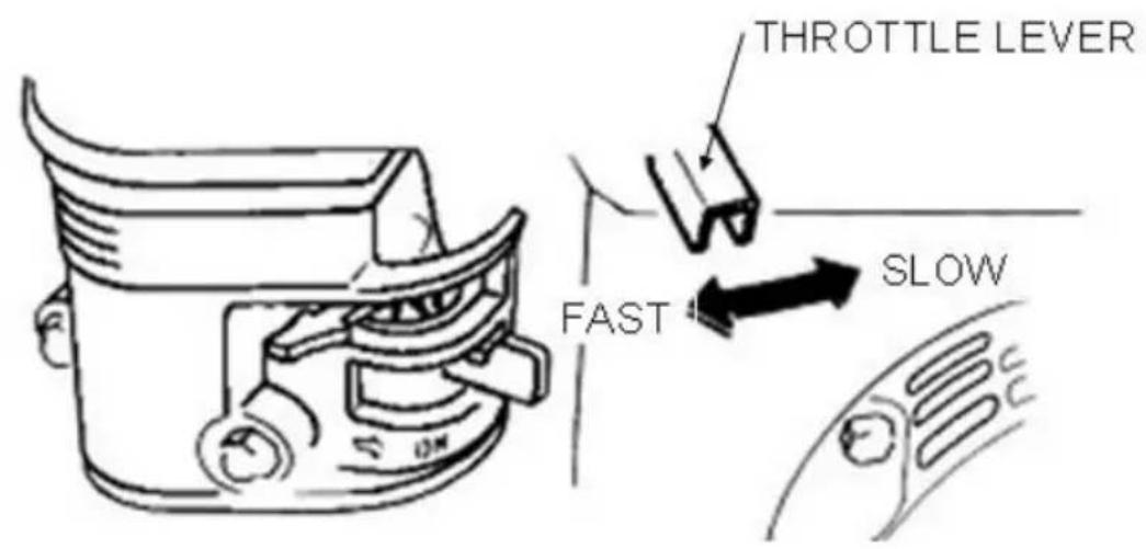
Throttle Lever
The throttle lever controls engine THROTTLE LEVER speed.
Moving the throttle lever in the directions shown makes the engine run faster or slower.
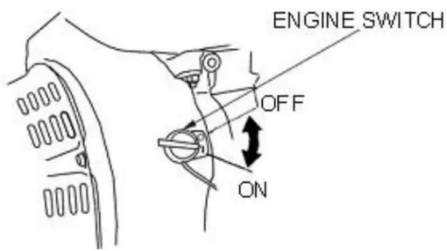
Engine Switch
The engine switch enables and disables the ignition system.
The engine switch must be in the ON position for the engine to run. Turning the engine switch to the OFF position stops the engine.
Choke Lever
The choke lever opens and closes the choke valve in the carburetor. The CLOSE position enriches the fuel mixture for starting a cold engi The OPEN position provides the correct fuel mixture for operation after starting, and for restarting a warm engine.
Some engine applications use a remotely-mounted choke control rather than the engine-mounted choke lever shown here.
Recoil Starter Grip
Pulling the starter grip operates the recoil starter to crank the engine.
For your safety, and to maximize the service life of your equipment, very important to take a few moments before you operate the engine check its condition. Be sure to take care of any problem you find, c your servicing dealer correct it, before you operate the engine.
WARNING
Improperly maintaining this engine,or failing to correct a problem before operation, could cause a malfunction in which you could I seriously injured.Always perform a preoperation inspection before each operation,and correct any problem.
Before beginning your preoperation checks, be sure the engine is level the engine switch is in the OFF position.
Check the General Condition of the Engine
- Look around and underneath the engine for signs of oil or gasoline
-
Remove any excessive dirt or debris, especially around the muffler recoil starter.
-
Look for signs of damage.
- Check that all shields and covers are in place, and all nuts, bolts, screws are tightened.
Check the Engine
Check the engine oil level. Running the engine with a low oil level cause engine damage.
The Oil Alert system (applicable engine types) will automatically stop the engine before the oil level falls below safe limits. However, to avoid inconvenience of an unexpected shutdown, always check the engine or level before startup.
Check the air filter. A dirty air filter will restrict air flow to the carbu reducing engine performance.
Check the fuel level. Starting with a full tank will help to eliminate operating interruptions for refueling.
Check the Equipment Powered by This Engine
Review the instructions provided with the equipment powered by this engine for any precautions and procedures that should be followed by engine startup.
5. OPERATION
SAFE OPERATING PRECAUTIONS
Before operating the engine for the first time, please review the IMPORTANT SAFETY INFORMATION and the chapter titled BEFORE OPERATION.
WARNING
Carbon monoxide gas is toxic.
Breathing it can cause unconsciousness and even kill you.
Avoid any areas or actions that expose you to carbon monoxide.
Review the instructions provided with the equipment powered by this
engine for any safety precautions that should be observed in conjunct with engine startup, shutdown, or operation.
STARTING THE ENGINE
- Move the fuel valve lever to the ON position.
- To start a cold engine, move the choke lever to the CLOSE position. To restart a warm engine, leave the choke lever in the OPEN position. Some engine applications use a remotely-mounted choke control rather than the engine-mounted choke lever shown here.
- Move the throttle lever away from the SLOW position, about 1/3 c
way toward the FAST position.
Some engine applications use a remotely-mounted throttle control rather than the engine-mounted throttle lever shown here.
- Turn the engine switch to the ON position.

- Operate the starter.
RECOIL STARTER (all engine types):
Pull the starter grip lightly until you feel resistance, then pull briskly.
Return the starter grip gently.

- If the choke lever has been moved to the CLOSE position to sta engine, gradually move it to the OPEN position as the engine warms
STOPPING THE ENGINE
To stop the engine in an emergency, simply turn the engine switch 1 OFF position. Under normal conditions, use the following procedure.
- Move the throttle lever to the SLOW position.
Some engine applications use a remotely-mounted throttle control rather than the engine-mounted throttle lever shown here.
- Turn the engine switch to the OFF position.
- Turn the fuel valve lever to the OFF position.
SETTING ENGINE SPEED
Position the throttle lever for the desired engine speed.
Some engine applications use a remotely-mounted throttle control rather than the engine-mounted throttle lever shown here.
For engine speed recommendations, refer to the instructions provided by the equipment powered by this engine.

6. MAINTENANCE
THE IMPORTANCE OF MAINTENANCE
Good maintenance is essential for safe, economical, and trouble-free operation. It will also help reduce air pollution.
WARNING
Improperly maintaining this engine, or failure to correct a problem before operation, can cause a malfunction in which you can be seriously hurt killed.
Always follow the inspection and maintenance recommendations and schedules in this owner's manual.
To help you properly care for your engine, the following pages include maintenance schedule, routine inspection procedures, and simple maintenance procedures using basic hand tools. Other service tasks tr
are more difficult, or require special tools, are best handled by professionals and are normally performed by a technician or other qual mechanic.
The maintenance schedule applies to normal operating conditions. If you operate your engine under unusual conditions, such as sustained high-load or high-temperature operation, or use in unusually wet or due conditions, consult your servicing dealer for recommendations applicable to your individual needs and use.
MAINTENANCE SAFETY
Some of the most important safety precautions are as follows: However, we cannot warn you of every conceivable hazard that can arise in performing maintenance. Only you can decide whether or not you show perform a given task.
WARNING
Failure to properly follow maintenance instructions and precautions can cause you to be seriously hurt or killed.
Always follow the procedures and precautions in the owner's manual.
Safety Precautions
- Make sure the engine is off before you begin any maintenance or This will eliminate several potential hazards:
◆ Carbon monoxide poisoning from engine exhaust.
Be sure there is adequate ventilation whenever you operate the engin
◆ Burns from hot parts.
Let the engine and exhaust system cool before touching.
♦ Injury from moving parts.
Do not run the engine unless instructed to do so.
- Read the instructions before you begin, and make sure you have t and skills required.
- To reduce the possibility of fire or explosion, be careful when work around gasoline. Use only a nonflammable solvent, not gasoline, to cl
parts. Keep cigarettes, sparks and flames away from all fuel-related p. Remember that your servicing dealer knows your engine best and is equipped to maintain and repair it.
To ensure the best quality and reliability, use only new, genuine parts their equivalents for repair and replacement.
MAINTENANCE SCHEDULE
| REGULAR SERVICE PERIOD Performed at every indicate month or operating hour interval, whichever comes first. | Each use | First month or 20 Hrs. | Every 3 months or 5 Hrs. | Every 6 months or 100 Hrs. | Every year or 300 Hrs. | ||
| ITEM | |||||||
| ● | Engine oil | Check level | ○ | ||||
| Change | ○ | ○ | |||||
| ● | Air cleaner | Check | ○ | ||||
| Clean | ○(1) | ||||||
| Replace | ○☆ | ||||||
| ● | Sediment Cup | Clean | ○ | ||||
| ● | Spark plug | Check-Clean | ○ | ||||
| Replace | ○ | ||||||
| Spark arrester (optional parts) | Clean | ○ | |||||
| ● | Idle speed | Check-Adjust | ○(2) | ||||
| ● | Valve clearance | Check-Adjust | ○(2) | ||||
| ● | Fuel tank and strainer | Clean | ○(2) | ||||
| ● | Combustion chamber | Clean | After every 300 Hrs. (2) | ||||
| ● | Fuel line | Check | Every 2 years (Replace if necessary | ||||
- Emission-related items.
☆ Replace the paper element type only.
(1)Service more frequently when used in dusty areas.
(2) These items should be serviced by your servicing dealer unless you have the proper tools and are mechanically proficient. Refer to manual service procedures.
FUEL RECOMMENDATIONS
Use unleaded gasoline with a pump octane rating of 86 or highe
These engines are certified to operate on unleaded gasoline. Unleaded gasoline produces fewer engine and spark plug deposits and extends exhaust system life.
Never use stale or contaminated gasoline or an oil/gasoline mixture. A getting dirt or water in the fuel tank.
Occasionally you may hear a light “spark knock” or “pinging” (metallic rapping noise) while operating under heavy loads. This is no cause for concern.
If spark knock or pinging occurs at a steady engine speed, under no load, change brands of gasoline. If spark knock or pinging persists, s authorized servicing dealer.
NOTICE
Running the engine with persistent spark knock or pinging can cause engine damage.
Running the engine with persistent spark knock or pinging is considered misuse, and the Distributor's Limited Warranty does not cover parts
damaged by misuse.
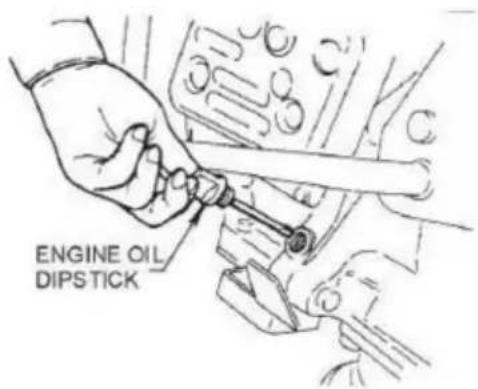
ENGINE OIL LEVEL CHECK
Check the engine oil level with the engine stopped and in a level p 1. Remove the filler cap/dipstick and wipe it clean.
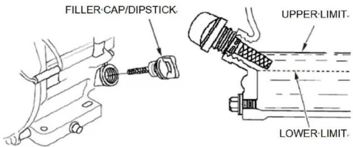
- Insert and remove the dipstick without screwing it into the filler ne Check the oil level shown on the dipstick.
- If the oil level is low, fill to the edge of the oil filler hole with t recommended oil.
- Screw in the filler cap/dipstick securely.
NOTICE
Running the engine with a low oil level can cause engine damage. The Oil Alert system (applicable engine types) will automatically stop the engine before the oil level falls below safe limit. However, to avoid the inconvenience of an unexpected shutdown, always check the engine or level before startup.
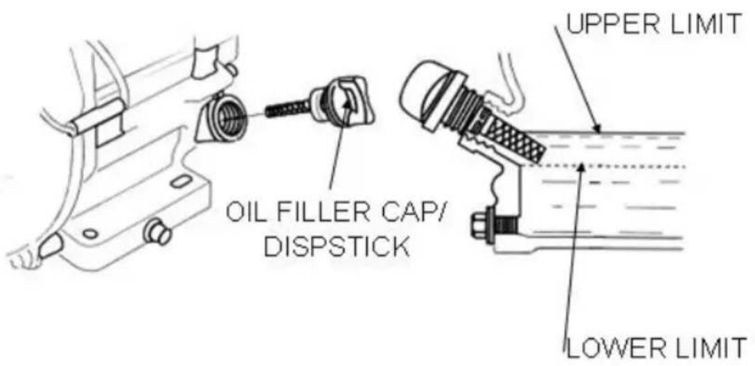
ENGINE OIL CHANGE
Drain the used oil while the engine is warm. Warm oil drains quickly completely.
- Place a suitable container below the engine to catch the used oil, then remove the filler cap/dipstick and the drain plug.
- Allow the used oil to drain completely, and then reinstall the drain and tighten it securely.
Please dispose of used motor oil in a manner that is compatible with environment. We suggest you take used oil in a sealed container to local recycling center or service station for reclamation. Do not throw the trash; pour it on the ground; or down a drain.
- With the engine in a level position, fill to the outer edge of the hole with the recommended oil.
Engine oil capacities:
LC168F-2H: 0.63 US qt (0.60 L)
Running the engine with a low oil level can cause engine damage. However, to avoid the inconvenience of an unexpected shutdown, fill the upper limit, and check the oil level regularly.
- Screw in the filler cap/dipstick securely.
REDUCTION GEAR OIL (Only on equipped model)
- Remove the oil filler cap and wipe the dipstick clean.
- Insert the dipstick into the filler neck but do not screw it in.
- If the level is low, fill to the upper level mark with the same oil
recommended for the engine.
SERVICING YOUR ENGINE
ENGINE OIL RECOMMENDATIONS
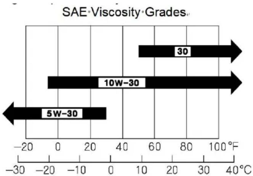
Oil is a major factor affecting performance and service life. Use 4-str automotive detergent oil.
SAE 10W-30 is recommended for general use. Other viscosities show the chart may be used when the average temperature in your area is the recommended range.
SAE Viscosity Grades
bar
SAE®Viscosity®Grades. | Grade | SAE®Viscosity (degrees) | | :--- | :--- | | 30 | 50 | | 10W-30 | -10 | | 5W-30 | -20 |AMBIENT·TEMPERATURE
The SAE oil viscosity and service classification are in the API label of oil container. We recommend that you use API SERVICE Category SF oil.
AIR FILTER INSPECTION
Remove the air cleaner cover and inspect the filter. Clean or replace filter elements. Always replace damaged filter elements.
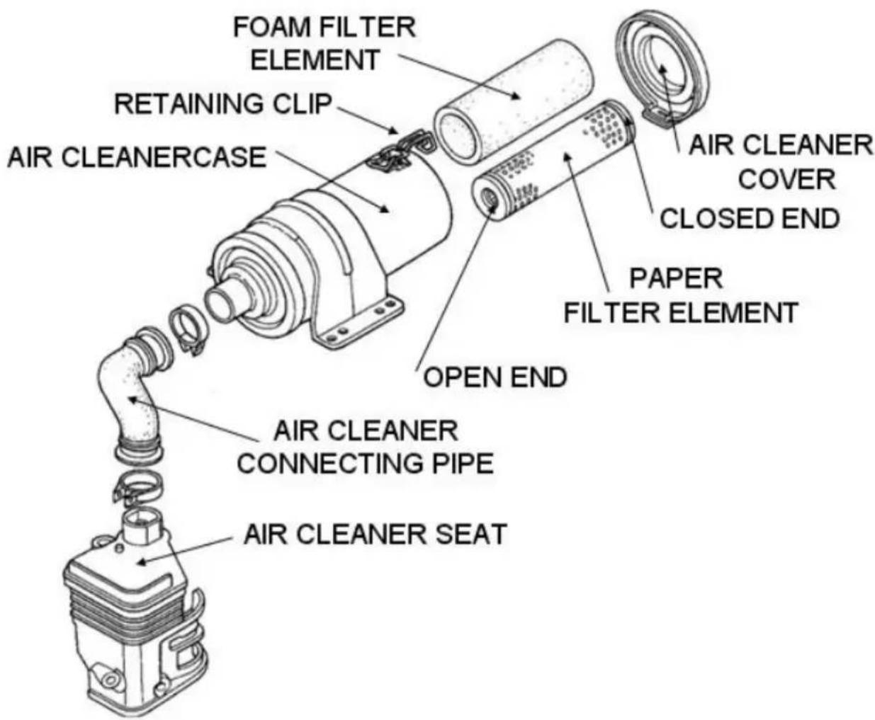
AIR CLEANER SERVICE
A dirty air filter will restrict air flow to the carburetor, reducing engine performance.
If you operate the engine in very dusty areas, clean the air filter more than specified in the MAINTENANCE SCHEDULE.
NOTICE
Operating the engine without an air filter, or with a damaged air filter allow dirt to enter the engine, causing rapid engine wear. This type of damage is not covered by the Distributor's Limited Warranty.
-
Unfold the retaining clip from the air cleaner case, and remove the cleaner cover.
-
Remove the filter.
-
Remove the foam filter element from the paper filter element.
- Inspect both air filter elements, and replace them if they are damaged. Always replace the paper air filter element at the scheduled interval.
- Clean the air filter elements if they are to be reused.
Paper filter element: Tap the filter element several times on a hard s to remove dirt, or blow compressed air [not exceeding 30 psi (207 k through the filter element from the inside. Never try to brush off dirt; brushing will force dirt into the fibers.
Foam filter element: Clean in warm soapy water, rinse, and allow dry thoroughly. Or clean in nonflammable solvent and allow drying. Dip the filter element in clean engine oil, and then squeeze out all excess oil engine will smoke when started if too much oil is left in the foam.
- Wipe dirt from the inside of the air cleaner seat, base and cover, use moist rag. Be careful to prevent dirt from entering the air duct that I use the carburetor.
- Place the foam filter element over the paper element, and reinstall assembled air filter. Be sure the open end of the Paper filter element the air cleaner connecting pipe.
- Install the air cleaner cover, and tighten the retaining clip securely.
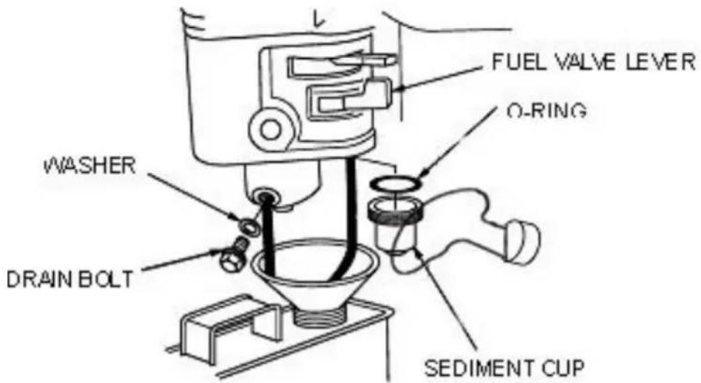
SEDIMENT CUP CLEANING
- Move the fuel valve to the OFF position, and then remove the fuel sediment cup and O-ring.
Gasoline is highly flammable and explosive.
You can be burned or seriously injured when handling fuel.
WARNING
Keep heat, sparks and flame away.
Handle fuel only outdoors.
Wipe up spills immediately.
- Wash the sediment cup and O-ring in nonflammable solvent, and dr them thoroughly.
- Place the O-ring in the fuel valve, and install the sediment cup. Tig
the sediment cup securely.
- Move the fuel valve to the ON position, and check for leaks. Replace O-ring if there is any leakage.
SPARK PLUG SERVICE
Recommended spark plugs: F7RTC or other equivalents.
NOTICE
An incorrect spark plug can cause engine damage.
- Disconnect the spark plug cap, and remove any dirt from around spark plug area.
- Remove the spark plug with a spark plug wrench.
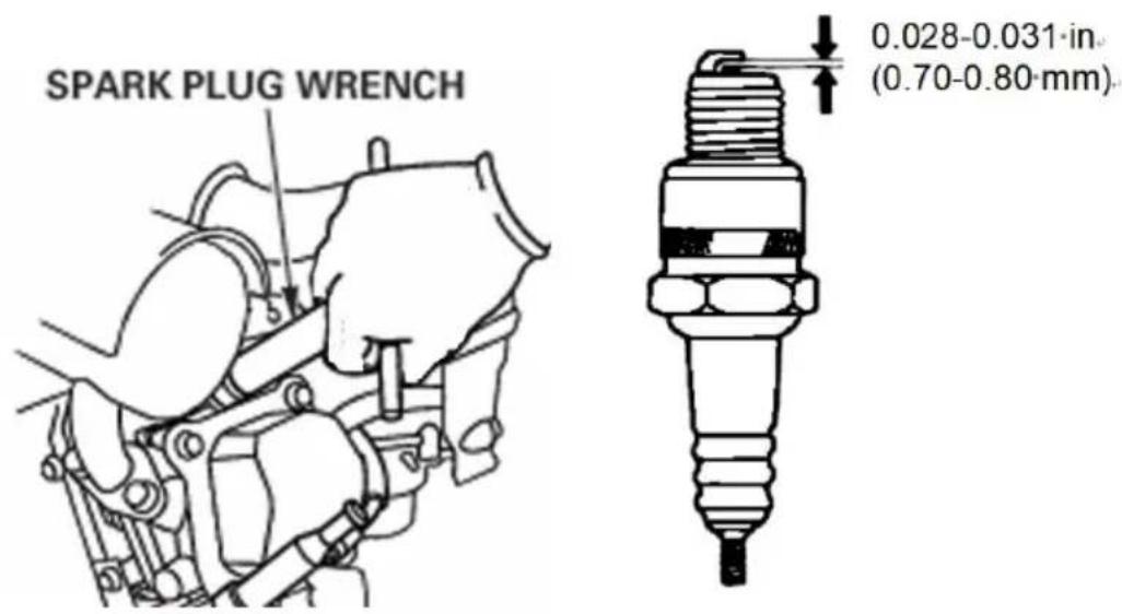
- Inspect the spark plug. Replace it if the electrodes are worn, or i insulator is cracked or chipped.
- Measure the spark plug electrode gap with a suitable gauge.
The gap should be 0.028 -0.031 in (0.70 - 0.80 mm). Correct the gap necessary, by carefully bending the side electrode.
- Install the spark plug carefully, by hand, to avoid cross-threading.
- After the spark plug seats, tighten with a spark plug wrench to cut the water.
If reinstalling the used spark plug, tighten 1/8 - 1/4 turn after the spare seats.
If installing a new spark plug, tighten 1/2 turn after the spark plug s
NOTICE
A loose spark plug can overheat and damage the engine.
Over tightening the spark plug can damage the threads in the cylinder head.
- Attach the spark plug cap.
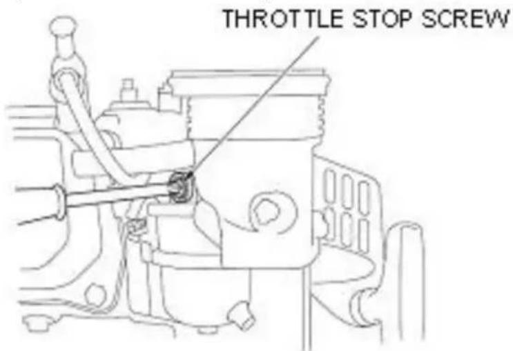
IDLE SPEED ADJUSTMENT
- Start the engine outdoors, and allow it to warm up to operating temperature.
- Move the throttle lever to its slowest position.
- Turn the throttle stop screw to obtain the standard idle speed.
Standard idle speed: 1800±150 rpm
7. STORAGE/ TRANSPORTING
STORING YOUR ENGINE
Storage Preparation
Proper storage preparation is essential for keeping your engine trouble and looking good. The following steps will help to keep rust and confrom impairing your engine's function and appearance, and will make engine easier to start after storage.
Cleaning
If the engine has been running, allow it to cool for at least half an before cleaning. Clean all exterior surfaces, touch up any damaged pa and coat other areas that may rust with a light film of oil.
NOTICE
- Using a garden hose or pressure washing equipment can force water the air cleaner or muffler opening. Water in the air cleaner will soak filter, and water that passes through the air filter or muffler can enter cylinder, causing damage.
• Water contacting a hot engine can cause damage. If the engine has running, allow it to cool for at least half an hour before washing.
Fuel
Gasoline will oxidize and deteriorate in storage. Old gasoline will cause hard starting, and it leaves gum deposits that clog the fuel system. I gasoline in your engine deteriorates during storage, you may need to the carburetor and other fuel system components serviced or replaced. The length of time that gasoline can be left in your fuel tank and could without causing functional problems will vary with such factors as gas blend, your storage temperatures, and whether the fuel tank is partially completely filled. The air in a partially filled fuel tank promotes fuel deterioration. Very warm storage/temperatures accelerate fuel deterioration. Fuel deterioration problems may occur within a few months
or even less if the gasoline was not fresh when you filled the fuel. The Distributor's Limited Warranty does not cover fuel system damage engine performance problems resulting from neglected storage preparation.
You can extend fuel storage life by adding a fuel stabilizer that is formulated for that purpose, or you can avoid fuel deterioration problem by draining the fuel tank and carburetor.
ADDING A FUEL STABILIZER TO EXTEND FUEL STORAGE LIFE
When adding a fuel stabilizer, fill the fuel tank with fresh gasoline. If partially filled, air in the tank will promote fuel deterioration during stop. If you keep a container of gasoline for refueling, be sure that it con- only fresh gasoline.
- Add fuel stabilizer following the manufacturer's instructions.
- After adding a fuel stabilizer, run the engine outdoors for 10 minutes be sure that treated gasoline has replaced the untreated gasoline in carburetor.
- Stop the engine, and move the fuel valve to the OFF position.
DRAINING THE FUEL TANK AND CARBURETOR
- Place an approved gasoline container below the carburetor, and use funnel to avoid spilling fuel.
- Remove the carburetor drain bolt and sediment cup, and then move fuel valve lever to the ON position.
- After all the fuel has drain into the container, reinstall the drain bol sediment cup. Tighten them securely.
WARNING
- The length of time that gasoline can be left in your fuel tank and carburetor without causing functional problems will vary with such facts as gasoline blend, your storage temperatures, and whether the fuel ta partially or completely filled.
The air in a partially filled fuel tank promotes fuel deterioration. Very storage temperatures accelerate fuel deterioration. Gasoline will oxidize and deteriorate in storage. Deteriorated gasoline will cause hard starting and it leaves gum deposits that clog the fuel system. As a result, if engine is not used for more than one month, the fuel oil shall be thoroughly to prevent from deterioration of the fuel in fuel system and carburetor.
- The failures of fuel system or engine performance arising from imprint storage are beyond the scope of the warranty.
Storage Precautions
- Change the engine oil.
- Remove the spark plugs.
- Pour a tablespoon (5-10 cc) of clean engine oil into the cylinder.
- Pull the starter rope several times to distribute the oil in the cylinder
- Reinstall the spark plugs.
- Pull the starter rope slowly until resistance is felt. This will close the valves so moisture cannot enter the engine cylinder. Return the starter rope gently.
If your engine will be stored with gasoline in the fuel tank and carbus is important to reduce the hazard of gasoline vapor ignition. Select a well-ventilated storage area away from any appliance that operates with flame, such as a furnace, water heater, or clothes dryer. Also avoid area with a spark-producing electric motor, or where power tools are
operated.
If possible, avoid storage areas with high humidity, because that prom rust and corrosion.
Unless all fuel has been drained from the fuel tank, leave the fuel v lever in the OFF position to reduce the possibility of fuel leakage.
Position the equipment so the engine is level. Tilting can cause fuel leakage.
With the engine and exhaust system cool, cover the engine to keep dust. A hot engine and exhaust system can ignite or melt some mat Do not use sheet plastic as a dust cover. A nonporous cover will tra moisture around the engine, promoting rust and corrosion.
If equipped with a battery for an electric starter, recharge the battery month while the engine is in storage. This will help to extend the set of the battery.
Removal from Storage
Check your engine as described in the chapter CHECK BEFORE OPERATION.
If the fuel was drained during storage preparation, fill the tank with f gasoline. If you keep a container of gasoline for refueling, be sure th contains only fresh gasoline. Gasoline oxidizes and deteriorates over ti causing hard starting.
If the cylinders were coated with oil during storage preparation, the e may smoke briefly at startup. This is normal.
TRANSPORTING
If the engine has been running, allow it to cool for at least 15 minutes before loading the engine-powered equipment on the transport vehicle. Hot engine and exhaust system can burn you and can ignite some materials.
Keep the engine level when transporting to reduce the possibility of f leakage. Move the fuel valve lever to the OFF position.
8.TROUBLESHOOTING
| ENGINE WILL NOT START | Possible Cause | Correction |
| Electric starting: check battery | Battery discharged. | Recharge battery. |
| 2. Check control positions | Fuel valve OFF. | Move lever to ON. |
| Choke OPEN. | Move lever to CLOS unless engine is warm. | |
| Engine switch OFF. | Turn engine switch ON. | |
| 3. Check fuel. | Out of fuel. | Refuel |
| Bad fuel; engine stor without treating or draining gasoline, or refueled with bad gasoline. | Drain fuel tank and carburetor. Refuel with fresh gasoline. | |
| 4. Remove and inspe spark plugs. | Spark plugs faulty, fouled, or improperly gapped. | Gap, or replace spa plugs. |
| Spark plugs wet with fuel (flooded engine). | Dry and reinstall spark plugs. Start engine with throttle lever in FAST position. | |
| 5. Take engine to ar authorized servicing dealer, or refer to manual. | Fuel filter clogged, carburetor malfunction, ignition malfunction, valve stuck, etc. | Replace or repair faulty components as necessary. |
| ENGINE LACKS POWER | Possible Cause | Correction |
| 1. Check air filter | Filter element(s) clogged. | Clean or replace filt element(s). |
| 2. Check fuel. | Out of fuel. | Refuel |
| Bad fuel; engine stored without treating or draining gasoline, refueled with bad gasoline. | Drain fuel tank and carburetor. Refuel with fresh gasoline. | |
| 3.Take engine to an authorized servicing dealer, or refer to manual. | Fuel filter clogged, carburetor malfunction, ignition malfunction, valve stuck, etc. | Replace or repair faulty components as necessary. |
9. TECHNICAL & CONSUMER INFORMATION
TECHNICAL INFORMATION
Serial Number Location
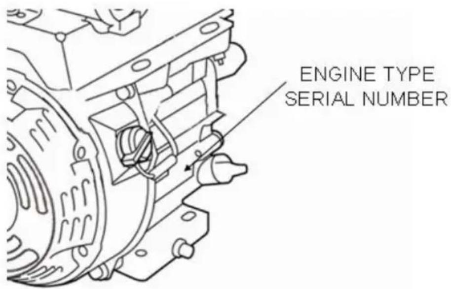
Record the engine serial number in the space below. You will need serial number when ordering parts, and when making technical or war inquires.
Engine serial number:
©
modification is made.
NOTICE
When the carburetor has been modified for high altitude operation, the air-fuel mixture will be too lean for low altitude use. Operation at alti below 5,000 feet (1,500 meters) with a modified carburetor may cause engine to overheat and result in serious engine damage. For use at altitudes, have your servicing dealer return the carburetor to original fat specifications.
Oxygenated Fuels
Some conventional gasolines are being blended with alcohol or an eth compound. These gasolines are collectively referred to as oxygenated fuels.
To meet clean air standards, some areas use oxygenated fuels to be reduce emissions.
If you use an oxygenated fuel, be sure it is unleaded and meets the minimum octane rating requirement.
Before using an oxygenated fuel, try to confirm the fuel's contents. S areas require this information to be posted on the pump.
The following are the EPA approved percentages of oxygenates:
ETHANOL ——(ethyl or grain alcohol) 10% by volume
You may use gasoline containing up to 10% ethanol by volume. Gas containing ethanol may be marketed under the name “Gasohol”.
MTBE ——(methyl tertiary butyl ether) 15% by volume
You may use gasoline containing up to 15% MTBE by volume.
METHANOL ——(methyl or wood alcohol) 5% by volume
You may use gasoline containing up to 5 % methanol by volume, as it also contains cosolvents and corrosion inhibitors to protect the fuel system. Gasoline containing more than 5 % methanol by volume may cause starting and/or performance problems. It may also damage metal rubber, and plastic parts of your fuel system. If you notice any under operating symptoms, try another service station, or switch to another I
of gasoline.
Fuel system damage or performance problems resulting from the use oxygenated fuel containing more than the percentages of oxygenates mentioned above are not covered under warranty.
Emission Control System Information
Source of Emissions
The combustion process produces carbon monoxide, oxides of nitrogen and hydrocarbons. Control of hydrocarbons and oxides of nitrogen is important because, under certain conditions, they react to form photochemical smog when subjected to sunlight. Carbon monoxide does not react in the same way, but it is toxic.
This utilizes lean carburetor settings and other systems to reduce the emissions of carbon monoxide, oxides of nitrogen and hydrocarbons. Tampering and Altering
Tampering with or altering the emission control system may increase emissions beyond the legal limit. Among those acts that constitute tampering are:
- Removal or alteration of any part of the intake, fuel or exhaust sy
- Altering or defeating the governor linkage or speed-adjusting mechan to cause the engine to operate outside its design parameters.
Problems That May Affect Emissions
If you are aware of any of the following symptoms, have your engine inspected and repaired by your servicing dealer.
- Hard starting or stalling after starting.
- Rough idle.
- Misfiring or backfiring under load.
• Afterburning (backfiring). - Black exhaust smoke or high fuel consumption.
Replacement Parts
The emission control systems on your engine were designed, built. W
recommend the use of genuine parts whenever you have maintenance done. These original-design replacement parts are manufactured to the same standards as the original parts, so you can be confident of the performance. The use of replacement parts that are not of the original design and quality may impair the effectiveness of your emission control system.
A manufacturer of an aftermarket part assumes the responsibility that part will not adversely affect emission performance. The manufacturer rebuilder of the part must certify that use of the part will not result failure of the engine to comply with emission regulations.
Maintenance
Follow the maintenance schedule. Remember that this schedule is based on the assumption that your machine will be used for its designed p Sustained high-load or high-temperature operation, or use in unusually or dusty conditions, will require more frequent service.
Engine Tune-up
| ITEM | SPECIFICATION |
| Spark plug gap | 0.028 in -0.031 in(0.70 mm -0.80 mm) |
| Valve clearance | IN: 0.15 mm±0.02 mm (cold)EX: 0.20 mm±0.02 mm (cold) |
| Other specifications | No other adjustments needed |
CONSUMER INFORMATION
Publications
These publications will give you additional information for maintaining a repairing your engine. You may order them from your engine dealer.
Parts Catalog
This manual provides complete, illustrated parts lists.
QUICK REFERENCE INFORMATION
| Engine Oil | Type | SAE 10W-30,API SE or SF, for ge use |
| Capacity | 160/200F(D):0.6 L | |
| Spark Plug | Type | F7RTC or other equivalents. |
| Gap | 0.028—0.031 in (0.70 mm—0.80 mr | |
| Carburetor | Idle speed | 1800 rpm±150 rpm |
| Maintenance | Each use | Check engine oil. Check air filter |
| First 20 hour | Change engine oil. | |
| Subsequent | Refer to the maintenance |
10.Specifications
| Model | LC168F-2H |
| Type | Single cylinder, 4-Stroke, Forced Air Cooling, OHV |
| Rated power(kW/3600rpm) | 4.1 |
| Max. torque(N·m/rpm) | 12.4/2500 |
| Fuel consumption(g/kW·h) | ≤395 |
| Idle speed | 1800±150 |
| SpeedFluctuating Ratio | ≤10% |
| Noise(≤) | 70 |
| Bore×Stroke(mm) | 68×54 |
| Displacement(cc) | 196 |
| Compression Ratio | 8.5:1 |
| Lubricating mode | Splash |
| Starting Mode | Recoil start |
| Rotation | Anti-clockwise(from P.T.O. side) |
| Valve Clearance | Input valve: 0.10 mm ~0.15mm, Output valve: 0.15 mm ~0.20mm |
| Spark plug clearance | 0.7 mm ~0.8mm |
| Igniting Mode | Transistorized magneto Ignition |
| Air cleaner | Foam filter |
| Dimension(Length) (mm) | 380 |
| Dimension(Width) (mm) | 335 |
| Dimension(High) (mm) | 390 |
| Net weight(kg) | 16 |
The power rating of the engine indicated in this document is the net output tested on a production engine for the engine model and meas in accordance with SAE J1349 at 3,600 rpm (Net Power) and at 2,5 (Max. Net Torque). Mass production engines may vary from this value. Actual power output for the engine installed in the final machine will depending on numerous factors, including the operating speed of the engine in application, environmental conditions, maintenance, and other variables.
11. Wiring Diagrams
| BI | BLACK |
| Y | YELLOW |
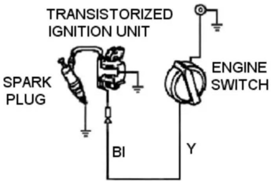
Manufacturer: Shanghaimuxinmuyeyouxiangongsi
Address: Shuangchenglu 803nong11hao1602A-1609shi, baoshanqu, shanghai 200000 CN.
Imported to AUS: SIHAO PTY LTD. 1 ROKEVA STREETEASTWOOD NSW 2122 Australia
Imported to USA: Sanven Technology Ltd. Suite 250, 9166 Anaheim Place, Rancho Cucamonga, CA 91730
| UK | REP |
YH CONSULTING LIMITED. C/O YH Consultin Limited Office 147, Centurion House, London Road, Staines-upon-Thames, Surrey, TW18 4A>
| EC | REP |
Technical Support and E-Warranty Certificate
www.vevor.com/support
VEVOR®
TOUGH TOOLS, HALF PRICE
natural_image
Technical line drawing of a mechanical pump assembly (no text or symbols)BESOIN D'AIDE? CONTACTEZ-NOUS!
RECOMMANDATIONS DE CARBURANT
charge. • Postcombustion (retours
YH CONSULTING LIMITED. C/O YH Consulting Limited Bureau 147, Centurion House, London Road, Staines-upon-Thames, Surrey, TW18 4AX
| REPRÉSENTANT DE LA CE |
E-CrossStu GmbH
Mainzer Landstr.69,
natural_image
Technical line drawing of a mechanical pump assembly (no text or symbols)YH CONSULTING LIMITED. C/O YH Consulting Limited Office 147, Centurion House, London Road, Staines-upon-Thames, Surrey, TW18 4AX
www.vevor.com/support
VEVOR®
TOUGH TOOLS, HALF PRICE
natural_image
Technical line drawing of a mechanical pump assembly (no text or symbols)Importato in AUS: SIHAO PTY LTD. 1 ROKEVA STREETEASTWOOD NSW 2122 Australia
Importato negli USA: Sanven Technology Ltd. Suite 250, 9166 Anaheim Place, Rancho Cucamonga, CA 91730

YH CONSULTING LIMITED. C/O YH Consulting Limited Ufficio 147, Centurion House, London Road, Staines- upon-Thames, Surrey, TW18 4AX

elettronica www.vevor.com/support
VEVOR®
TOUGH TOOLS, HALF PRICE
natural_image
Technical line drawing of a mechanical pump assembly (no text or symbols)Road, Staines-upon-Thames, Surrey, TW18 4AX

E-CrossStu GmbH
Mainzer Landstr.69,
natural_image
Technical line drawing of a mechanical pump assembly (no text or symbols)POTRZEBUJESZ POMOCY? SKONTAKTUJ SIĘ Z NAMI!
www.vevor.com/support
- ROZWIAZYWANIE PROBLEMÓ W
YH CONSULTING LIMITED. C/O YH Consulting Limited Biuro 147, Centurion House, London Road, Staines-upon-Thames, Surrey, TW18 4AX
| Przedstaw ciel UE |
E-CrossStu GmbH
Mainzer Landstr.69,
60329 Frankfurt nad Menem.
VEVOR®
TOUGH TOOLS, HALF PRICE
natural_image
Technical line drawing of a mechanical pump assembly (no text or symbols)HULP NODIG? NEEM CONTACT MET ONS OP!
www.vevor.com/support
YH CONSULTING LIMITED. C/O YH Consulting Limited Kantoor 147, Centurion House, London Road, Staines- upon-Thames, Surrey, TW18 4AX

E-CrossStu GmbH
Mainzer Landstr.69,
60329 Frankfurt am Main.
VEVOR®
TOUGH TOOLS, HALF PRICE
Technische ondersteuning en e-garantiecertificaat www.vevor.com/support
VEVOR®
TOUGH TOOLS, HALF PRICE
natural_image
Technical line drawing of a mechanical pump assembly (no text or symbols)BEHÖVER HJÄLP? KONTAKTA OSS!
INNEHÅLLSFÖRTECKNING
| Projekt | Paginering |
| 1. MOTORSÄKERHET | 4 |
| 2. KOMPONENTER OCH KONTROLLPLATSER | 5 |
| 3. KONTROLLER | 5 |
| 4. KONTROLLERA INNAN ANVÄNDNING | 8 |
| 5. DRIFT | 9 |
| 6. UNDERHÅLL | 15 |
| 7. LAGRING/TRANSPORT | 27 |
| 8. FELSÖKNING | 32 |
| 9. TEKNISK OCH KONSUMENTINFORMATION | 33 |
| 10. Specifikationer | 39 |
| 11. Kopplingsscheman | 40 |
1. MOTORSÄKERHET
VIKTIG SÄKERHETSINFORMATION
YH CONSULTING LIMITED. C/O YH Consulting Limited Office 147, Centurion House, London Road, Staines-upon-Thames, Surrey, TW18 4AX
| EC | REP |
www.vevor.com/support


