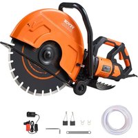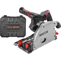
8140 - Saw Vevor - Free user manual and instructions
Find the device manual for free 8140 Vevor in PDF.


User questions about 8140 Vevor
0 question about this device. Answer the ones you know or ask your own.
Ask a new question about this device
Download the instructions for your Saw in PDF format for free! Find your manual 8140 - Vevor and take your electronic device back in hand. On this page are published all the documents necessary for the use of your device. 8140 by Vevor.
USER MANUAL 8140 Vevor
Technical Support and E-Warranty Certificate
www.vevor.com/support
TRACK SAW USER MANUAL
MODEL:8140
We continue to be committed to provide you tools with competitive price. "Save Half", "Half Price" or any other similar expressions used by us only represent of savings you might benefit from buying certain tools with us compared top brands and does not necessarily mean to cover all categories of tools offered are kindly reminded to verify carefully when you are placing an order with us actually saving half in comparison with the top major brands.
MODEL:8140
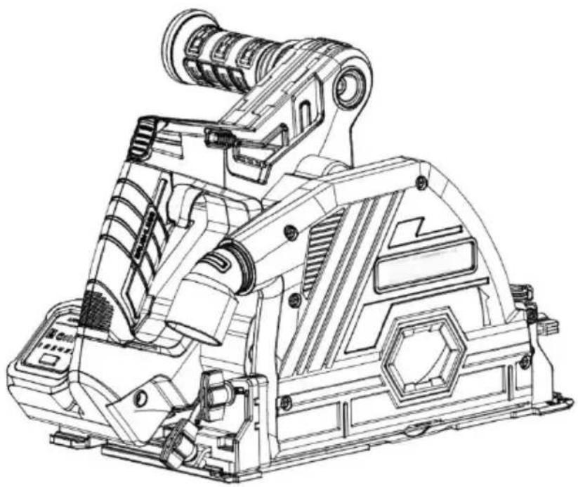
natural_image
Technical line drawing of a mechanical device with no visible text or symbols(The picture is for reference only, please refer to the actual obje
NEED HELP? CONTACT US!
Have product questions? Need technical support? Please feel fr contact us:
Technical Support and E-Warranty Certificate www.vevor.com/support
This is the original instruction, please read all manual instruction carefully before operating. VEVOR reserves a clear interpretation user manual. The appearance of the product shall be subject to product you received. Please forgive us that we won't inform you there are any technology or software updates on our product.
 | Warning-To reduce the risk of injury, user must read instru manual carefully. |
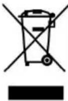 | This product is subject to the provision of European Direct 2012/19/EC. The symbol showing a wheelie bin crossed th indicates that the product requires separate refuse collection European Union. This applies to the product and all acces marked with this symbol. Products marked as such may no discarded with normal domestic waste, but must be taken collection point for recycling electrical and electronic devices |
General safety warning for power too
⚠️ Keep all warnings and instructions for future reference.
The term "power tool" in the warning means either a mains powered power tool or a battery powered (wireless) power tool.
Keep all warnings and instructions for future reference.
The term "power tool" in the warning means either a mains powered power tool or a battery powered (wireless) power tool.
a) Workplace safety
- Keep the workplace clean and bright. Messy and dark fields can I accidents.
- Do not operate power tools in explosive environments, such as flammable liquids, gases or dust. Sparks from power tools can ignite or gas.
- Keep power tools away from children and bystanders. A lack of concentration can cause you to lose control of your tools.
b) Electrical safety
- The plug of the power tool must match the socket. The plug must be modified in any way. Power tools that need to be grounded should use any adapter plugs. Unmodified plugs and matching sockets will re
the risk of electric shock.
- Keep your body away from ground surfaces, such as pipes, heat and refrigerators. If you touch a grounded surface, you increase the shock.
- Do not expose power tools to rain or humidity. Water entering power tools increase the risk of electric shock.
Do not abuse the cord. Never handle, pull, or unplug power tools with cords. Keep cords away from heat sources, oil, sharp edges, or movi parts. Damaged or entangled cords increase the risk of shock.
- When using power tools outdoors, use an extension cord suitable for outdoor use. Electrical wiring suitable for outdoor use will reduce the electric shock.
- Use a power supply with residual current device (RCD) protection if not possible to avoid operating the appliance in a humid environment. use of RCD reduces the risk of electric shock.
- Do not touch the power plug with wet hands.
- If the wire is damaged, it will be replaced by the manufacturer or to avoid safety hazards.
c) Personal safety
- Stay alert, pay attention to the operation and stay awake when open power tools. Do not operate electric tools when you are tired, or who have a reaction to drugs, alcohol, or treatment. Momentary negligence operating power tools can result in serious personal injury.
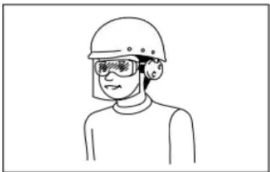
- Use personal protective equipment. Always wear safety goggles.
Protective devices, such as dust masks, non-slip safety shoes, hard hearing protection and other devices used under appropriate conditions can reduce personal injury.
- Remove all adjustment keys or wrenches before the power tool is switched on. A wrench or key left on a rotating part of a power tool result in personal injury.
-
Don't overextend your hands. Always pay attention to your footing balance. This allows for better control of power tools in the event of accident.
-
Dress appropriately. Don't wear loose clothing or accessories. Keep hair and clothes away from moving parts. Loose clothing, accessories, long hair may involve moving parts.
-
If a device is provided for connection with the chip removal and collection equipment, ensure that it is properly connected and used. The use of dust collection devices can reduce the risk of dust.
-
Don't let the familiarity of frequent tool use lead you to ignore the guidelines of the tool. A careless action can lead to serious injury in instant.
-
Always wear safety goggles when using power tools to avoid eye damage. Safety goggles must comply with ANSI Z87.1, European EN or Australia/New Zealand AS/ NZS 1336. In Australia/New Zealand, a is required by law to protect the face. It is the employer's responsibility ensure that tool operators and other personnel near the work area would appropriate safety equipment.
natural_image
Line drawing of a person wearing a helmet and safety goggles (no text or symbols)d) Power tools and precautions
-
Do not force the use of power tools, according to the use of app power tools. Choosing the right power tool designed according to the value will make you work more efficiently and safely.
-
If the switch cannot be turned on or off, do not use the power to Electric tools that cannot be controlled by a switch are dangerous an be repaired.
-
Unplug and/or remove the battery pack (if removable) from the power supply before any adjustment, replacement of accessories or storage of electrical equipment. This protective safety measure reduces the risk of accidental starting of power tools.
-
Store unused power tools outside the reach of children, and do not allow people who are not familiar with power tools and do not under these instructions to operate power tools. Power tools are dangerous hands of untrained users.
-
Maintain power tools and accessories. Check whether moving parts adjusted in place or stuck, check for broken parts and other condition affect the operation of power tools. If there is damage, repair the po before use. Many accidents are caused by poorly maintained power to
-
Keep cutting tools sharp and clean. A well-maintained tool with a sharp edge is less likely to stick and easier to control.
-
According to the instruction manual, and considering the working conditions and the operation to be carried out, choose the power tools, accessories and heads. Using power tools for operations that are not suitable for their purposes lead to dangerous situations.
-
Keep the handle and grip surface dry, clean, and free of grease. In the an accident, a slippery handle does not guarantee a safe grip and control of tool.
-
Do not wear cloth work gloves that may become entangled when using tool. Cloth work gloves involving moving parts may cause personal injury.
e) Maintenance
- Use the same spare parts to repair electric tools by professional maintenance personnel. This will ensure the safety of the power tools being serviced.
- Please follow the instructions in this manual when applying lubrication and replacing accessories.
Electric circular saws use safety warning
Danger:
a) Keep hands away from the sawing area and blade at all times. A hold the auxiliary handle or motor housing with your other hand. If y the circular saw with both hands, you won't be hurt by the blade.
b) Do not touch the underside of the work piece. The guard does not protect against the danger of the saw blade under the work piece. c) Adjust the cutting depth to the thickness of the work piece. The s visible under the work piece should be less than one tooth height. d) Do not hold the work piece or hold the work piece on the leg for the work piece should be clamped on a stable platform. Proper support the work piece is essential to reduce personal injury, saw blade jamn loss of control.
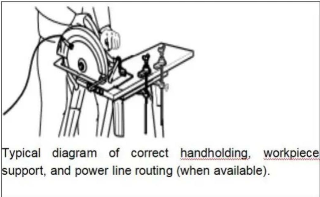
a) When the sawing work piece is operated, it is possible to touch dark line or its own wire. The machine must be held through an ins grip surface. Touching a "live" wire can also electrify the exposed me part of the tool, thus electrocuting the operator.
text_image
Typical diagram of correct handholding, workpiece support, and power line routing (when available).b) When used as a splitting saw, always use a splitting guard and straight edge guide. This improves the cutting accuracy and reduces the chance of the saw blade getting stuck.
c) Always use a saw blade with the right size and shaft shape (d or round). If the saw blade and the circular saw clamping parts do match, it will cause eccentric operation and lead to loss of control.
d) Damaged washers and bolts that do not match dimensions shall be used. For improved operation and safe operation, saw blade wash and bolts are specially designed for circular saws
Reasons for rebound and operator protection:
Rebound is the sudden reverse operation when the saw blade is squeezed, stuck, or off-center, causing the circular saw to lift uncontro and away from the work piece towards the operator.
When the saw blade is squeezed or tightly stuck by the closed cut, saw blade is blocked and the motor reaction force drives the machine snap back towards the operator.
If the blade is twisted or deviated from the cutting surface, the ser edges on the back edge of the blade can dig into the upper surface wood .causing the blade to crawl out of the cut and bounce back to the operator.
Rebound is the result of misuse of the circular saw and/or incorrect operating procedures or conditions, and can be avoided by taking appropriate precautions.
a) Grip the handle of the circular saw with both hands, and position upper arms enough to withstand the rebound. The body is on either the circular saw and not aligned with the blade. Rebound will cause the circular saw to spring back, but if proper precautions are taken, the rebound can be controlled by the operator.
b) When the saw blade is stuck, or the sawing is interrupted for any reason, release the switch trigger and hold the circular saw in the m without moving until the saw blade comes to a complete stop. Do no attempt to remove the saw from the workpiece or pull the saw back while the saw blade is in operation or is likely to spring back. Inves and take proper action to eliminate the cause of the saw blade stick
c) When restarting the circular saw in the workpiece, align the saw with the cut and check that the saw blade is inserted into the mater saw blade gets stuck, it will crawl out of the piece or bounce off th when the tool is restarted.
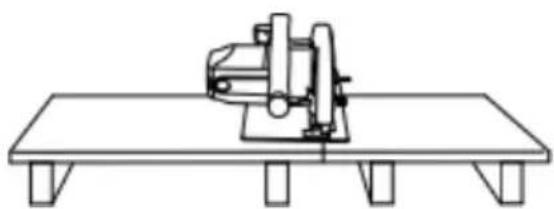
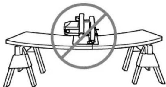
d) Support large sheet material to reduce the damage of saw blade extrusion and rebound. The large sheet material sags due to its own and the support material must be placed in the two measures below sheet material, near the cutting line and the edge of the sheet material
natural_image
Line drawing of a sewing machine on a flat workbench (no text or symbols)To avoid bouncing, place a support plate or panel close to the cut.
natural_image
Diagram of a table with two chairs and a central mechanical device, no text or symbols presentDo not place the support plate or pa from the cutting area.
a) Do not use dull or damaged saw blades. Saw blades with no edge or improperly installed can form narrow saw marks, which can be severe friction, stuck blades, and rebound.
b) Cutting depth and Angle adjustment locking buttons must be tigh and secured before sawing. If the blade regulator moves while sawing may cause the blade to jam and rebound.
c) Take extra care when "insert sawing" on existing walls or other areas. Sticking out the saw blade may cut an object that causes reb
Guard rebound description
a) Before each use, check that the cover is closed freely. If the lock guard does not return quickly, do not operate the circular saw. Do not or tie the lower guard in the open position. If the circular saw is suddenly dropped, the lower guard may bend out of shape. Lift the lower guard a retracted handle and make sure that the guard rears at any cutting and depth without touching the saw blade or any other part.
b) Check the working condition of the lower guard spring. If the guard and spring do not work properly, they must be repaired before use.
lower guard may be slow to move due to damage to parts, gum de or waste buildup.
c) Lift the lower guard manually only for special sawing, such as sawing" and "combined sawing". Lift the lower guard with the retractal handle. The lower guard must be released as soon as the saw blade the sawing material. For all other sawing operations, the lower guard should return automatically
d) Always ensure that the lower guard covers the saw blade before placing the circular saw on the table or the ground. An unprotected, saw blade causes the circular saw to retreat and cut an object on it taking into account the time the saw blade stops after the switch is released.
Additional security warning
-
Be especially careful when cutting wet wood, pressurized wood, trees that contain knobs. Without reducing the speed of the saw blade keep the tool smoothly pushed to avoid overheating of the serrations, well as to avoid the plastic melting when cutting.
-
Do not attempt to remove the cutting material when the saw blade moving. Wait until the saw blade has stopped completely beforegrabbing the cutting material. The saw blade will still move some distance after power is turned off.
-
Be careful not to cut into nails. Check wood for nails and remove before cutting.
-
When cutting, please place the wider part of the base of the circular saw on the part of the work piece that is firmly supported, the part that will be cut down. If the work piece is short or small, Do not try to hold short pieces!
-
Be especially careful when cutting wet wood, pressurized wood, or that contain knobs. Without reducing the speed of the saw blade, keep tool smoothly pushed to avoid overheating of the serrations, as well as avoid the plastic melting when cutting.
-
Do not attempt to remove the cutting material while the blade is
Wait until the saw blade has stopped completely before grabbing the cutting material. The saw blade will still move some distance after the power is turned off.
-
Be careful not to cut into nails. Check wood for nails and remove before cutting.
-
When cutting, please place the wider part of the base of the electric circular saw on the part of the work piece that is firmly supported, the part that will be cut down. If the work piece is short or small, Do not try to hold short pieces!
5.Before putting down the tool after cutting, ensure that the lower protective cover is closed and the saw blade is completely stopped.
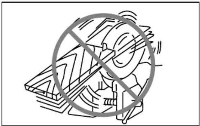
- Do not attempt to cut with an electric circular saw held backward vice. This is very dangerous and can lead to serious accidents.
natural_image
Illustration of a person crossed out of a large mechanical component, no text or symbols present-
Some materials contain toxic chemicals. Be careful not to inhale d and avoid skin contact. Follow the material supplier's safety tips.
-
Do not stop the saw blade by applying side pressure to it.
-
Do not use any grinding wheel.
-
Only use saw blades of the diameter indicated on the tool or spin in the instructions. Using an incorrectly sized saw blade can affect the proper protection of the saw blade or the operation of the protective resulting in serious personal injury.
-
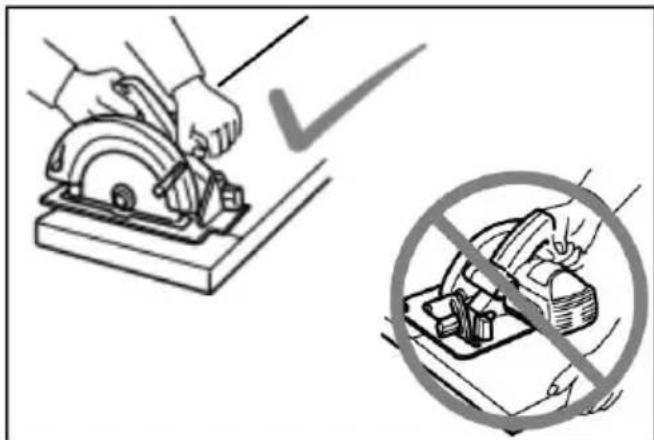
Keep the saw blade sharp and clean. Resin and wood bitumen are stuck on the blade and harden can slow down the electric circular surface increase the likelihood of rebound. Therefore, remove the saw blade from the tool first, and then clean it with resin and asphalt remover, hot water kerosene.
text_image
Diagram illustrating a manual tool and a prohibition symbol for cutting wood, with checkmark indicating selection.Keep the saw blade clean. Do not use gasoline.
- Wear a dust mask and protective earmuffs when using tools.
- Be sure to use a saw blade suitable for the material being cut.
- Only use saw blades whose marked speed is equal to or greater the speed indicated on the tool.
Please keep this manual.
Do not follow the relevant product safety rules for convenience or better you are familiar enough with the product (experience gained due to risk). Improper use or failure to follow the safety rules in the instruction made can result in serious personal injury.
Product specification
- Due to the ongoing development program, we reserve the right to change the specifications without notice.
| Item No. | 8140 | |
| Blade Diameter | 140 mm | |
| Cutting depth | 90° | 52 mm |
| 45° | 38 mm | |
| No Load Speed (RPM) | 3500-5500 | |
| Safety level | III | |
Note: The product does not come with a battery, and you to purchase a suitable battery. The track saw is compatible v Makita's 20V pin battery pa (Such as: BL1850B1 BL1840B
Operation instruction
- Switch operation
text_image
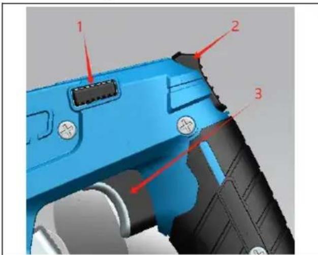
Labeled diagram of a blue handheld device showing three numbered components with red arrows pointing to features.- Lock button;
- push rod
- Switch
Before turning on the power, make sure to check whether the button is active normally and is in the open and normal closed state. In order to prevent the user from accidentally pulling the trigger of the switch, the tool adopts a locking mechanism. When the cutting operation required, the locking button is pushed to one side, and the switch be activated after the push rod is pushed to the top. Then the cutting can be performed
● Storage of hexagonal wrench
text_image
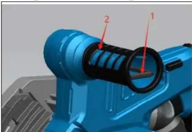
3D mechanical component diagram with numbered parts labeled 1 and 21 .Hex wrench
2 .Additional handle
The hex key is stored on the tool. To remove the hex key, pull it to install the Allen wrench, place it on the handle and insert it as possible.
- Remove or install the saw blade
Note:
- Do not use saw blades that do not conform to the specifications specified in this manual.
- The blade speed used should at least reach the maximum no-load speed in the specification value
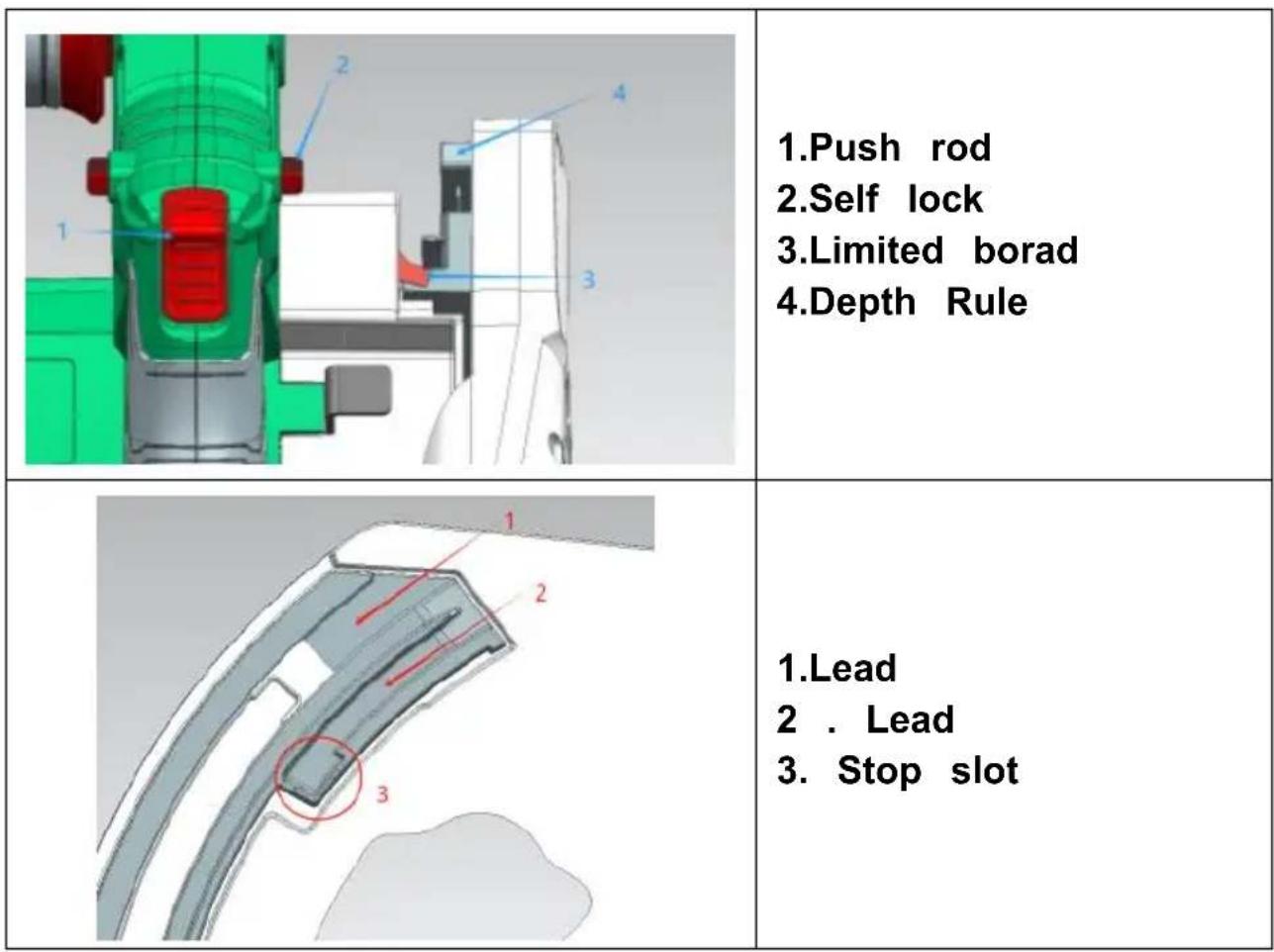
1.Push rod
2.Self lock
- Limited borad
4.Depth Rule
-
Lead
-
Lead
-
Stop slot
Step 1: To facilitate the removal of the saw blade, the depth ruler is designed with two lead slots. When removing the saw blade, push the to the right while pushing the rod up, push the limit plate into the lead 2, release the push rod and press the handle down, and the li will be embedded in the stop slot.
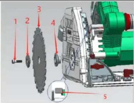
Step 2: Fully press the self-locking, rotate the saw blade until the saw blade cannot be turned, then use a wrench to turn counterclockwise to loosen the screw of the press knife, and then remove the screw of
press knife and the external pressure plate, and remove the saw black from the bottom.
If the machine is not in Step 1 state when you want to install the repeat Step 1 and do the opposite of step 2. Lock the knife screw clockwise.
text_image
1 2 3 4 5-
Press screw
-
External press plate
3.Blade
- Inner flange
5.Self lock
- Adjust the cutting depth
text_image
Technical diagram of a mechanical component with numbered parts and red annotation lines indicating features-
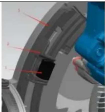
Push Button
-
Depth adjustment plate
-
Depth gauge
Press the push button on the depth adjustment plate, and move th scale on the depth adjustment plate to the required depth, release th button and spring back. (The A/B scale corresponds to the cutting de without guide rail/with guide rail)
In order to make the cutting more clean and safe, please adjust the depth to the position of no more than one tooth below the workpiece. The proper cutting depth can reduce the potential for personal injury by the saw blade bouncing.
- Bevel cutting
text_image
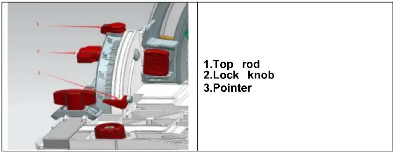
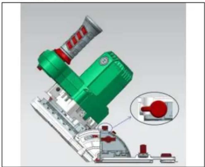
1.Top rod 2.Lock knob 3.Pointer-1°-47°Tilt
natural_image
3D mechanical assembly diagram showing green and red components with a close-up inset of a red valve (no text or symbols)0^ - 45^ : Loosen the front and rear locking knobs, tilt the machine observe the pointer indicating the scale, point it at the desired Angle, the locking knobs on both sides, so that it is fixed.
-1°/47° : To get -1°/47° oblique cutting Angle, turn the top rod to in the picture below, tilt the machine, when the pointer points to -1% tighten the locking knobs on both sides to make it fixed.
Note: Set the saw blade back to the correct Angle to set the ejection back.
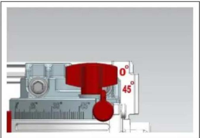
Alignment at
text_image
0° 45°Align the cutting line with the 0^ scale line on the base plate w cut is performed, and align the cutting line with the 45^ scale line o plate when a 45^ cut is performed.
● cutting (conventional sawing)
Attention:
Be sure to gently move the tool forward in a straight line. Applying excessive pressure to the tool or twisting the tool can cause the most overheat and cause the tool to rebound, potentially resulting in serious injury.
Never place any part of your body under the base of the tool when especially at the beginning of the cut. Otherwise, serious injury may I The saw blade is exposed below the tool base.
natural_image
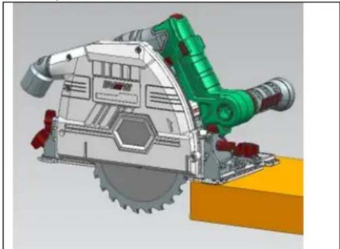
3D technical illustration of a mechanical cutting tool with green and red components (no text or symbols)Hold on to the tools. This tool is equipped with both an auxiliary I and a handle. Using both handles at the same time is the best way the tool. If both hands are on the circular saw, the blade won't cut
The front of the base is placed on the workpiece for cutting without contact with the saw blade. Then start the tool according to the switch operation and wait until the saw blade reaches full speed. Now, gently press the circular saw head down to the preset cutting depth, then s move the tool forward on the surface of the workpiece to keep it sn and flat until the cutting operation is complete.
To make the cutting cleaner, make sure the tool cuts in a straight at a consistent forward speed. If the actual cutting line is different from planned cutting line, do not attempt to turn or push the tool back to originally planned cutting line. Doing so may cause the saw blade to stuck and cause the tool to bounce or possibly cause serious injury. Release the switch, wait for the saw blade to stop and then pull back to tool. Align the tool with the new cutting line and start cutting again. determining the cutting position, try to avoid exposing the operator to debris and sawdust sprayed by the chainsaw. Wear safety goggles to injury.
- When using guide rail (optional accessories)
text_image
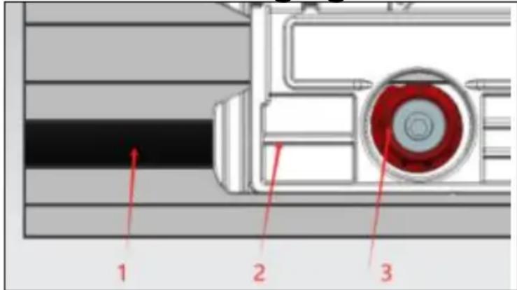
1 2 3- Guide rail
2.Bottom plate
3.Eccentric wheel
Place the tool at the end of the guide rail. Turn the two eccentric v the tool base so that the tool can slide smoothly. Hold on to the tool is equipped with both a secondary handle and a handle. Using handles at the same time is the best way to grip the tool. Open the press the tool down to the preset cutting depth (the B scale line on depth adjustment board corresponds to the cutting depth when there i guide rail), and then cut.
• guide ruler (optional)
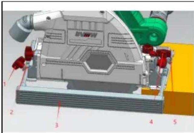
Angle gauges can be used for oblique cutting at different angles. A guide allows you to make more accurate straight cuts. Just insert guide ruler into the groove reserved on the bottom plate and lock the ruler knob, the guide ruler can be pressed tightly by pressing the front back press ruler plates, and adjust inside and outside according to the required cutting width, so that repeated cutting of the same width is possible.
text_image
Technical diagram of a mechanical assembly with numbered components and labeled parts1、4. Press rule knob;
2. Rear pressure ruler plate;
3. Guide ruler;
5.Front press plate
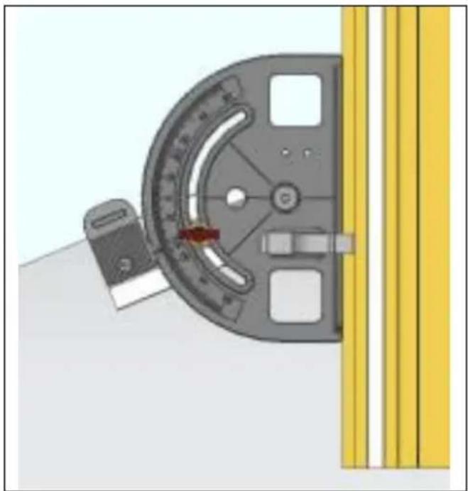
● Angle gauge (optional accessories)
Angle gauges can be used for oblique cutting at different angles.
natural_image
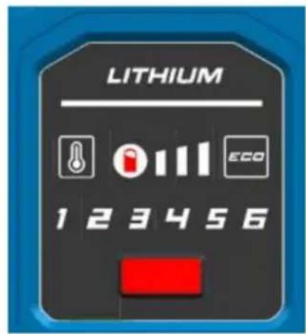
Diagram of a mechanical component with a curved dial and attached bracket, next to yellow vertical bars (no text or symbols)● Functional indication
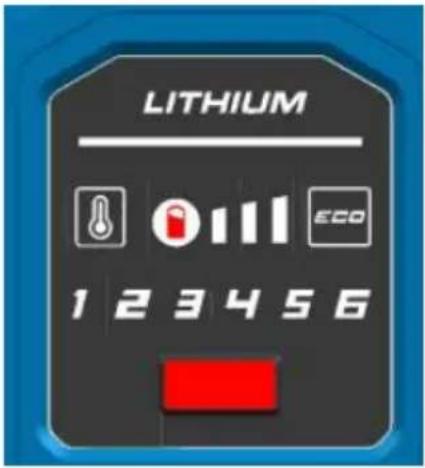 |  | Temperatureindicator,normally green,high temperature alarm is |
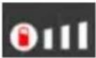 | Electric quantity display | |
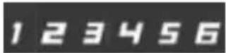 | Each speed gear | |
 | Energy saving gear |
Upkeep
△ Attention:
- Before preparing for inspection or maintenance, be sure to turn off switch and unplug the tool.
- Clean the protective cover to ensure the removal of accumulated sawdust that may impede the operation of the protective cover system dirty protective cover system may limit its operation, resulting in serious injury. The most effective way to complete the cleaning is to use compressed air. If you blow sawdust out of the protective cover, make you wear proper safety glasses and respiratory protection.
- Do not use gasoline, benzene, thinner, alcohol or similar materials to clean tools. Otherwise, the tool may become discolored, deformed, or cracked.
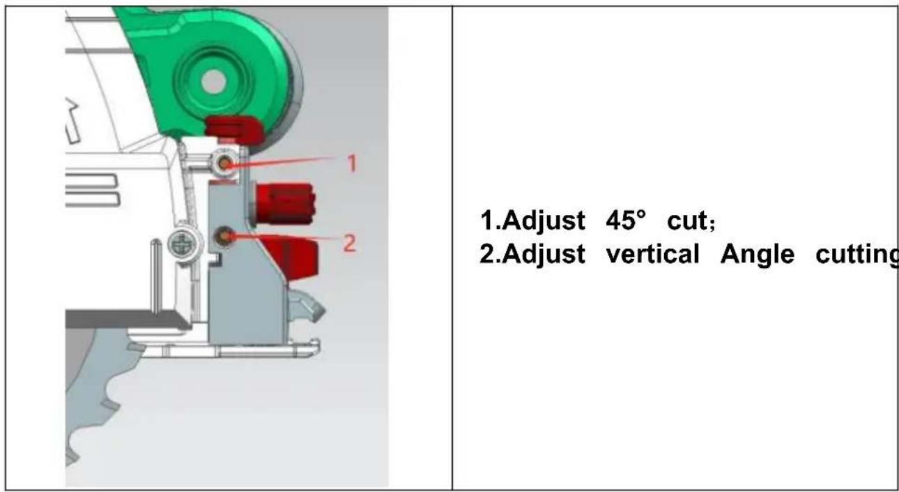
Adjust the accuracy of 45^ cutting and vertical cutting
This adjustment has been completed before the product leaves the face. However, if the tool is turned off, use the hex wrench to adjust the screw, and check the 90^ or 45^ saw blade with a three-edge rule as an Angle rule.
text_image
1. Adjust 45° cut; 2.Adjust vertical Angle cuttingThese accessories or devices are intended for use with power tools I in this specification. If other accessories or devices are used, there is of injury. Optional accessories or devices may only be used for the specified purpose.
- Guide rail
- Guide ruler
- Angle gauge
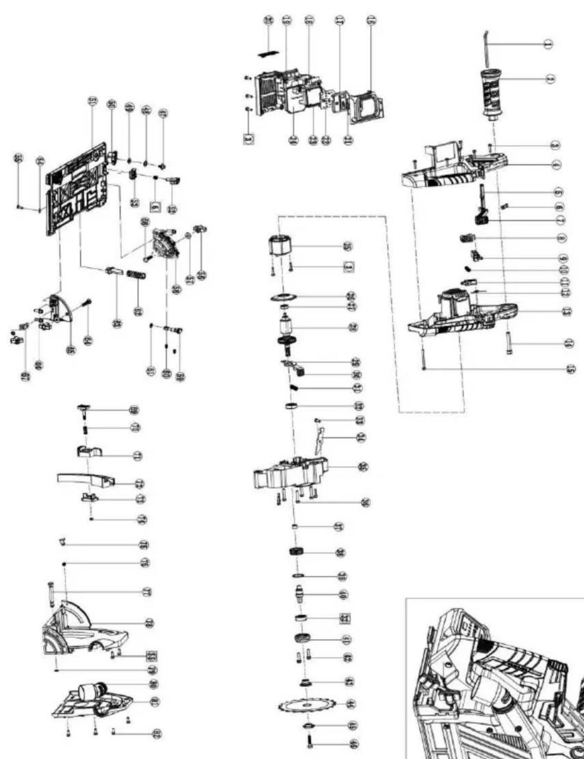
| serial number | Name specification | serial number | Name specification | serial number | Name specification |
| 1 | inner hexagon spanner | 29 | self-lock | 57 | flat gasket |
| 2 | Auxiliary handle | 30 | Self-locking sleeve | 58 | Front leg |
| 3 | Cross pan head tapping screw | 31 | Self-locking spring | 59 | knock-out pin |
| 4 | Handle cover | 32 | Deep groove ball bearing 6000 | 60 | holding screw |
| 5 | shackle | 33 | Phillips pan head screw M5*15 | 61 | O ring |
| 6 | 80165 push rod spring | 34 | Limit plate | 62 | return spring |
| 7 | push rod | 35 | gear case | 63 | Spring frame |
| 8 | Switch button (encapsulated) | 36 | Cross pan head tapping screw | 64 | Small semi-circular square diameter screw |
| 9 | Switch guide rod | 37 | Needle roller bearing HK0808 | 65 | Rear leg |
| 10 | Switch spring | 38 | main gear | 66 | socket head screw |
| 11 | switch | 39 | Retaining ring for φ26 hole | 67 | Rear ruler plate |
| 12 | torsional spring | 40 | output shaft | 68 | Small semi-circular square diameter screw |
| 13 | Chassis handle | 41 | front cover | 69 | Push button |
| 14 | socket head screw | 42 | Cross pan head screw | 70 | Push button spring |
| 15 | Cross pan head tapping screw | 43 | Internal pressure plate | 71 | Depth adjusting plate |
| 16 | Display cover plate | 44 | 140 saw blade | 72 | depthometer |
| 17 | Display frame | 45 | External pressure plate | 73 | Ruler buckle |
| 18 | Makita pin | 46 | Press knife screw | 74 | Lock nut M4 |
| 19 | Controller box | 47 | hexagon socket head cap screws | 75 | needle |
| 20 | Word board | 48 | flat gasket | 76 | Cross pan head screw |
| 21 | Display film pasting | 49 | Corrugated gasket | 77 | sell |
| 22 | indicator | 50 | eccentric (wheel) | 78 | Shaft retaining ring φ8 |
| 23 | Positioning frame | 51 | baseboard | 79 | Shaft retaining ring φ8 |
| 24 | controller | 52 | Ruler knob | 80 | Dust outlet pipe |
| 25 | stator | 53 | Front ruler plate | 81 | Head shell cover |
| 26 | Windproof ring | 54 | flat gasket | 82 | Cross pan head screw |
| 27 | Deep groove ball bearing 607 | 55 | Cross pan head tapping screw | ||
| 28 | rotator | 56 | Locking knob |
natural_image
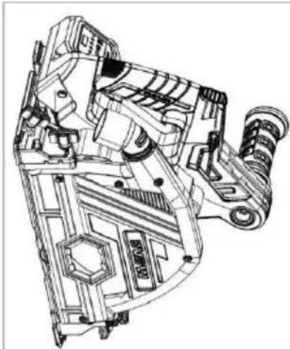
Technical line drawing of a mechanical assembly with gears and housing (no text or symbols)Manufacturer: Shanghaimuxinmuyeyouxiangongsi
Address: Shuangchenglu 803nong11hao1602A-1609shi, baoshanqu, shanghai 200000 CN.
Imported to AUS: SIHAO PTY LTD, 1 ROKEVA STREETEASTWOOD NS 2122 Australia
Imported to USA: Sanven Technology Ltd., Suite 250, 9166 Anaheim Pla Rancho Cucamonga, CA 91730
| EC | REP |
E-CrossStu GmbH
Mainzer Landstr.69, 60329 Frankfurt am Ma
| UK | REP |
YH CONSULTING LIMITED.
C/O YH Consulting Limited Office 147, Centurion H
London Road, Staines-upon-Thames, Surrey, TW18 4
VEVOR®
TOUGH TOOLS, HALF PRICE
Technical Support and E-Warranty Certificate
www.vevor.com/support
VEVOR®
TOUGH TOOLS, HALF PRICE
natural_image
Technical line drawing of a mechanical device with no visible text or symbolsnatural_image
Line drawing of a person wearing a helmet and safety goggles (no text or symbols)natural_image
Line drawing of a person using a power tool on a cutting board (no text or symbols)Typical diagram of correct handholding, workpiece support, and power line routing (when available).
natural_image
Line drawing of a sewing machine on a flat workbench (no text or symbols)natural_image
Diagram of a table with four legs and a central object, no text or symbols presentnatural_image
Illustration of a person crossed out of a large mechanical component, no text or symbols presenttext_image
Diagram illustrating a manual tool and a prohibition symbol for cutting wood, with checkmark and crossed-out instruction.text_image
Labeled diagram of a blue game controller with numbered components and red arrows indicating parts of the body.text_image
3D model of a blue mechanical component with numbered callouts pointing to features 1 and 2.text_image
Technical diagram showing mechanical components with numbered annotations and a blue tool interacting with a componenttext_image
Technical diagram of a mechanical assembly with numbered components and red indicator lightsnatural_image
3D mechanical assembly diagram showing green and red components with a close-up inset of a red component (no text or symbols)natural_image
3D CAD model of a mechanical cutting tool with green and red components, no visible text or symbolsnatural_image
3D mechanical assembly diagram showing a robotic arm and housing components (no text or symbols visible)natural_image
Mechanical component with a circular dial and attached bracket, next to vertical yellow bars (no text or symbols visible)natural_image
Technical line drawing of a mechanical assembly (no text or symbols visible)Fabricant : Shanghaimuxinmuyeyouxiangongsi
Adresse : Shuangchenglu 803nong11hao1602A-1609shi, baoshanqu, Shanghai
200000 CN.
Importé en Australie : SIHAO PTY LTD, 1 ROKEVA STREET, ASTWOOD NSW
2122 Australie
C/O YH Consulting Limited Bureau 147, Centurion House,
Route de Londres, Staines-upon-Thames, Surrey, TW18 4AX
VEVOR®
TOUGH TOOLS, HALF PRICE
www.vevor.com/support
BENUTZERHANDBUCH FÜR DIE SCHIENENSÄGE
MODELL:8140
natural_image
Technical line drawing of a mechanical device with no visible text or symbolsnatural_image
Line drawing of a person wearing a helmet and safety goggles (no text or symbols)natural_image
Line drawing of a person using a power tool on a cutting board (no text or symbols)Typical diagram of correct handholding, workpiece support, and power line routing (when available).
natural_image
Line drawing of a sewing machine on a flat workbench (no text or symbols)natural_image
Diagram of a table with four legs and a central object, no text or symbols presentnatural_image
Illustration of a person crossed out of a large mechanical component, no text or symbols presenttext_image
Diagram illustrating a manual tool and a prohibition symbol for cutting wood, with checkmark and crossed-out instruction.text_image
Labeled diagram of a blue game controller with numbered components and red arrows indicating parts of the body.- Sperrknopf; 2.
Schubstange;
- Schalter

text_image
3D mechanical component diagram with numbered parts labeled 1 and 2text_image
Technical diagram showing mechanical components with numbered annotations and a blue robotic arm interacting with a blue tool.text_image
Technical diagram of a mechanical assembly with numbered components and red directional arrows indicating motion or force directions.natural_image
3D mechanical assembly diagram showing green and red components with a close-up inset of a red component (no text or symbols)natural_image
3D CAD model of a mechanical cutting tool with green and red components, no visible text or symbolsnatural_image
3D mechanical assembly diagram showing a robotic arm and housing components (no text or symbols visible)natural_image
Mechanical component with a curved dial and attached bracket, next to vertical yellow bars (no text or symbols visible)ÿ Funktionsanzeige
text_image
LITHIUM 1 2 3 4 5 6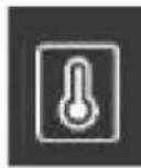
Temperatur
natural_image
Technical line drawing of a mechanical assembly (no text or symbols visible)Hersteller: Shanghaimuxinmuyeyouxiangongsi
Adresse: Shuangchenglu 803nong11hao1602A-1609shi, baoshanqu, Shanghai 200000 CN.
Nach AUS importiert: SIHAO PTY LTD, 1 ROKEVA STREETEASTWOOD NSW 2122 Australien
Importiert in die USA: Sanven Technology Ltd., Suite 250, 9166 Anaheim Place, Rancho Cucamonga, CA 91730
C/O YH Consulting Limited Office 147, Centurion House,
London Road, Staines-upon-Thames, Surrey, TW18 4AX
VEVOR®
TOUGH TOOLS, HALF PRICE
www.vevor.com/support
VEVOR®
TOUGH TOOLS, HALF PRICE
elettronica www.vevor.com/support
MANUALE D'USO DELLA SEGA A CINGOLI
MODELLO:8140
natural_image
Technical line drawing of a mechanical device with no visible text or symbolsnatural_image
Line drawing of a person wearing a helmet and safety goggles (no text or symbols)natural_image
Line drawing of a person using a power tool on a cutting board (no text or symbols)Typical diagram of correct handholding, workpiece support, and power line routing (when available).
natural_image
Line drawing of a sewing machine on a flat workbench (no text or symbols)natural_image
Simple line drawing of a table with four legs and a central object, no text or symbols present.natural_image
Illustration of a person crossed out of a large mechanical component, no text or symbols presenttext_image
Diagram illustrating a manual tool and a prohibition symbol for cutting wood, with checkmark and crossed-out instruction.text_image
Labeled diagram of a blue game controller with numbered components and red arrows indicating parts of the body.text_image
Technical diagram of a blue mechanical component with numbered parts labeled 1 and 2text_image
Technical diagram showing mechanical components with numbered annotations and a blue tool interacting with one part.text_image
Technical diagram of a mechanical assembly with numbered components and red directional arrows indicating motion or force directions.natural_image
3D mechanical assembly diagram showing green and red components with a close-up inset of a red component (no text or symbols)natural_image
3D CAD model of a mechanical cutting tool with green and red components, no visible text or symbolsnatural_image
3D mechanical assembly diagram showing a robotic arm and housing components (no text or symbols visible)natural_image
Mechanical component with curved dial and yellow vertical bars, no visible text or symbolsnatural_image
Technical line drawing of a mechanical assembly (no visible text or symbols)Importato in AUS: SIHAO PTY LTD, 1 ROKEVA STREETEASTWOOD NSW 2122 Australia
Importato negli USA: Sanven Technology Ltd., Suite 250, 9166 Anaheim Place, Rancho Cucamonga, CA 91730
natural_image
Technical line drawing of a mechanical device with no visible text or symbolsnatural_image
Line drawing of a person wearing a helmet and safety goggles (no text or symbols)natural_image
Line drawing of a person using a power tool on a cutting board (no text or symbols)Typical diagram of correct handholding, workpiece support, and power line routing (when available).
natural_image
Line drawing of a sewing machine on a flat workbench (no text or symbols)natural_image
Diagram of a table with supports and a central mechanical device, no text or symbols presentnatural_image
Illustration of a person crossed out of a large mechanical component, no text or symbols presenttext_image
Diagram illustrating a manual tool and a prohibition symbol for cutting wood, with checkmark and crossed-out instruction.text_image
Labeled diagram of a blue game controller with numbered components and red arrows indicating parts of the body.text_image
Technical diagram of a blue mechanical component with numbered parts labeled 1 and 21.Llave hexagonal;
- Asa adicional
text_image
Technical diagram showing mechanical components with numbered annotations and a blue tool interacting with a componenttext_image
Technical diagram of a mechanical assembly with numbered components and red directional arrows indicating motion or force directions.natural_image
3D mechanical assembly diagram showing green and red components with a close-up inset of a red component (no text or symbols)natural_image
3D CAD model of a mechanical cutting tool with green and red components, no visible text or symbolsnatural_image
3D mechanical assembly diagram showing a robotic arm and housing components (no text or symbols visible)natural_image
Mechanical component with a circular dial and attached bracket, next to vertical yellow bars (no text or symbols visible)natural_image
Technical line drawing of a mechanical assembly (no text or symbols visible)Fabricante: Shanghaimuxinmuyeyouxiangongsi
Dirección: Shuangchenglu 803nong11hao1602A-1609shi, baoshanqu, shanghai 200000 CN.
Importado a Australia: SIHAO PTY LTD, 1 ROKEVA STREETEASTWOOD NSW 2122 Australia
Importado a EE. UU.: Sanven Technology Ltd., Suite 250, 9166 Anaheim Place, Rancho Cucamonga, CA 91730
text_image
REPRESENTANTE CEE-CrossStu GmbH
natural_image
Technical line drawing of a mechanical device with internal components and mounting brackets (no text or symbols)natural_image
Line drawing of a person wearing a helmet and safety goggles (no text or symbols)natural_image
Line drawing of a person using a power tool on a cutting board (no text or symbols)Typical diagram of correct handholding, workpiece support, and power line routing (when available).
natural_image
Line drawing of a sewing machine on a flat workbench (no text or symbols)natural_image
Diagram of a table with four legs and a central object, no text or symbols presentnatural_image
Illustration of a person crossed out of a large mechanical component, no text or symbols presenttext_image
Diagram illustrating a manual tool and a prohibition symbol for cutting wood, with checkmark and crossed-out instruction.text_image
Labeled diagram of a blue game controller with numbered components and red arrows indicating parts of the body.- Przycisk blokady; 2.
Pręt popychający;
- Przełącznik

text_image
3D mechanical component diagram with labeled parts 1 and 2, showing blue housing and internal structuretext_image
Technical diagram showing mechanical components with numbered annotations and a blue robotic arm interacting with a blue tool.natural_image
3D mechanical assembly diagram showing green and red components with a close-up inset of a red component (no text or symbols)natural_image
3D mechanical assembly diagram showing a green and red tool interacting with a circular saw blade (no text or symbols visible)natural_image
3D mechanical assembly diagram showing a robotic arm and housing components (no text or symbols visible)natural_image
Mechanical component with a curved dial and attached bracket, next to vertical yellow bars (no text or symbols visible)natural_image
Technical line drawing of a mechanical assembly (no visible text or symbols)Producent: Shanghaimuxinmuyeyouxiangongsi
Adres: Shuangchenglu 803nong11hao1602A-1609shi, baoshanqu, szanghaj 200000 CN.
Importowane do AUS: SIHAO PTY LTD, 1 ROKEVA STREETEASTWOOD NSW 2122 Australia
Importowane do USA: Sanven Technology Ltd., Suite 250, 9166 Anaheim Place, Rancho Cucamonga, CA 91730
| Przedstaw ciel UE |
E-CrossStu GmbH
Mainzer Landstr.69, 60329 Frankfurt nad Menem.
| REP WIELKIEJ BRYTANII |
YH CONSULTING LIMITED.
C/O YH Consulting Limited Biuro 147, Centurion House, London Road, Staines-upon-Thames, Surrey, TW18 4AX
VEVOR®
TOUGH TOOLS, HALF PRICE
natural_image
Technical line drawing of a mechanical device with internal components and mounting brackets (no text or symbols)HULP NODIG? NEEM CONTACT MET ONS OP!
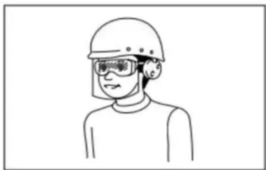
passende veiligheidsuitrusting.
natural_image
Line drawing of a person wearing a helmet and safety goggles (no text or symbols)natural_image
Line drawing of a person using a power tool on a cutting board (no text or symbols)Typical diagram of correct handholding, workpiece support, and power line routing (when available).
natural_image
Line drawing of a sewing machine on a flat workbench (no text or symbols)natural_image
Diagram of a table with four legs and a central object, no text or symbols presentnatural_image
Illustration of a person crossed out of a large mechanical component, no text or symbols presenttext_image
Diagram illustrating a manual tool and a prohibition symbol for cutting wood, with checkmark and crossed-out instruction.text_image
Labeled diagram of a blue game controller with numbered components and red arrows indicating parts of the body.- Vergrendelknop;
- Duwstang; 3.
Schakelaar

natural_image
Close-up of a blue mechanical component with labeled parts (1 and 2), no readable text or symbols beyond labels- Inbussleutel;
- Extra handgreep
text_image
Technical diagram showing mechanical components with numbered annotations and a blue tool interacting with a componentnatural_image
3D mechanical assembly diagram showing green and red components with a close-up inset of a red component (no text or symbols)natural_image
3D CAD model of a mechanical cutting tool with green and red components, no visible text or symbolsnatural_image
3D mechanical assembly diagram showing a robotic arm and housing components (no text or symbols visible)1ÿ4. Drukregelknopÿ 2.
natural_image
Mechanical component with a curved dial and attached bracket, next to vertical yellow bars (no text or symbols visible)ÿ Functionele indicatie
natural_image
Technical line drawing of a mechanical assembly (no visible text or symbols)Fabrikant: Shanghaimuxinmuyeyouxiangongsi
Adres: Shuangchenglu 803nong11hao1602A-1609shi, baoshanqu, shanghai 200000 CN.
C/O YH Consulting Limited Kantoor 147, Centurion House,
Londen Road, Staines-upon-Thames, Surrey, TW18 4AX
VEVOR®
TOUGH TOOLS, HALF PRICE
garantiecertificaat www.vevor.com/support
VEVOR®
TOUGH TOOLS, HALF PRICE
www.vevor.com/support
SPÅRSÅG ANVÄNDARHANDBOK
MODELL:8140
natural_image
Technical line drawing of a mechanical device with no visible text or symbolsnatural_image
Line drawing of a person wearing a helmet and safety goggles (no text or symbols)natural_image
Line drawing of a person using a power tool on a cutting board (no text or symbols)Typical diagram of correct handholding, workpiece support, and power line routing (when available).
natural_image
Line drawing of a sewing machine on a flat workbench (no text or symbols)natural_image
Diagram of a table with supports and a central mechanical device, no text or symbols presentnatural_image
Illustration of a person crossed out of a large mechanical component, no text or symbols presenttext_image
Diagram illustrating a manual tool and a prohibition symbol for cutting wood, with checkmark and crossed-out instruction.text_image
Labeled diagram of a blue handheld device with numbered components and red arrows indicating features- Låsknappÿ 2.
tryckstångÿ 3.
Brytare
natural_image
Close-up of a blue mechanical component with labeled parts (1 and 2), no readable text or symbols beyond labels1 .Insexnyckelÿ
- Extra handtag
text_image
Technical diagram showing mechanical components with numbered annotations and a blue robotic arm interacting with a blue tool.natural_image
3D mechanical assembly diagram showing green and red components with a close-up inset of a red component (no text or symbols)natural_image
3D mechanical assembly diagram showing a green and red tool interacting with a circular saw blade (no text or symbols visible)natural_image
3D mechanical assembly diagram showing a robotic arm and housing components (no text or symbols visible)natural_image
Mechanical component with a circular dial and attached bracket, next to vertical yellow bars (no text or symbols visible)natural_image
Technical line drawing of a mechanical assembly (no visible text or symbols)Tillverkare: Shanghaimuxinmuyeyouxiangongsi
Adress: Shuangchenglu 803nong11hao1602A-1609shi, baoshanqu, shanghai 200000 CN.
Importerad till AUS: SIHAO PTY LTD, 1 ROKEVA STREETEASTWOOD NSW 2122 Australien
Importerad till USA: Sanven Technology Ltd., Suite 250, 9166 Anaheim Place, Rancho Cucamonga, CA 91730
| EC | REP |
E-CrossStu GmbH
Mainzer Landstr.69, 60329 Frankfurt am Main.
| UK | REP |
YH CONSULTING LIMITED.
C/O YH Consulting Limited Office 147, Centurion House,
London Road, Staines-upon-Thames, Surrey, TW18 4AX
VEVOR®
TOUGH TOOLS, HALF PRICE
www.vevor.com/support