YDIES200L-E - Portable fuel tank Vevor - Free user manual and instructions
Find the device manual for free YDIES200L-E Vevor in PDF.

| Product type | Portable fuel tank with transfer pump |
| Brand | Vevor |
| Model | YDIES200L-E |
| Tank capacity | 200 liters |
| Tank material | High-density polyethylene, UV stabilized, red color |
| Power supply | 12 V DC (battery) via alligator clips |
| Pump power | 140 W |
| Flow rate | 40 L/min |
| Duty cycle | 30 minutes continuous dispensing; internal by-pass up to 2-3 minutes with trigger closed |
| Motor speed | 2300 rpm |
| Power cable length | 4 meters |
| Dispensing nozzle | Nozzle with automatic shut-off and swivel |
| Suction filter | Strainer filter on suction foot |
| Additional filter | Coarse filter at nozzle inlet (cleanable) |
| Compatible fuels | Diesel and gasoline (petrol / gasoline) |
| Thermal protection | Thermal overload protection device (automatic shut-off) |
| Routine maintenance | Clean the suction filter and nozzle filter periodically |
| Safety | Do not use indoors; secure the tank during transport; do not leave unattended while filling |
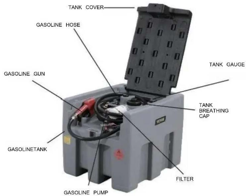
| Included accessories | Tank, pump, nozzle, hose, level gauge, filter, metal clamp, instruction manual |
| Repairability | Replaceable pump vanes and fuse; accessible check valve |
Frequently Asked Questions - YDIES200L-E Vevor
User questions about YDIES200L-E Vevor
0 question about this device. Answer the ones you know or ask your own.
Ask a new question about this device
Download the instructions for your Portable fuel tank in PDF format for free! Find your manual YDIES200L-E - Vevor and take your electronic device back in hand. On this page are published all the documents necessary for the use of your device. YDIES200L-E by Vevor.
USER MANUAL YDIES200L-E Vevor
Affordable. Reliable. Home Improvement.
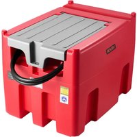
PORTABLE DIESEL&GASOLINE TANK
MODEL: YDIES200L-E/ YDIES400L-E
Technical Support and E-Warranty Certificate
www.vevor.com/support
VEVOR
Affordable. Reliable. Home Improvement.
PORTABLE DIESEI GASOLINE TAN
MODEL: YDIES200L-E/ YDIES400L-E

natural_image
Two identical gray industrial electrical enclosures with visible wiring and components, no text or symbols present.Photo for reference
This is the original instruction, please read all manual instructions care before operating. VEVOR reserves a clear interpretation of our user manual. The appearance of the product shall be subject to the product received. Please forgive us that we won't inform you again if there are technology or software updates on our product.
WARNING: Read carefully and understand all ASSEMBLY AND OPERATION INSTRUCTIONS before operating. Failure to follow the safety rules and other basic safety precautions may result in serious personal injury.
Part List
GENERAL:
All transfer units come standard with an Auto shut-off gun and all pumps feature a duty cycle for 30 minutes of continuous dispensing, all pumps also contain an internal bypass that allows for the pump to operate for up to a maximum of three minutes when the filling nozzle shuts off without damaging the pump or motor.
SPECIFICATIONS:
TANKS:
Made from impact resistant polyethylene, UV stabilized, coloured Red and fitted with lid and breather.
GUN: Trigger filling nozzle with automatic shut-off and hose swivel.
DELIVERY HOSE;4mx3/4 inch Diesel Delivery hose supplied.
FILTRATION: Suction foot screen filter
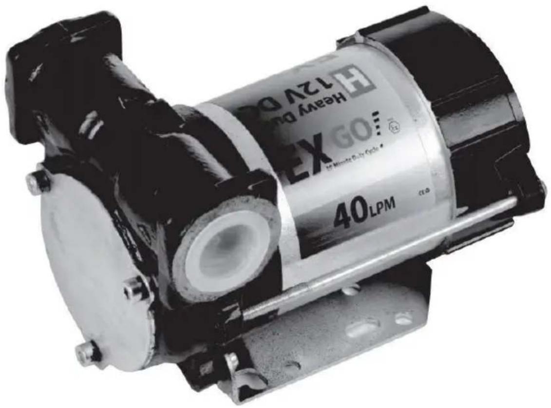
PUMPS:
| Power Output | Volts | Open Flow | Motor Duty Cycle | Internal Bypass | Power Cord | Motor Speed |
| 140W | 12V DC | 40L/min | 30 minutes | Yes | 4m with alligator clips | 2300RPM |
IMPORTANT OPERATIONAL NOTE-The internal bypass fitted in all diesel pump models is designed to protect the pump and motor from damage when the trigger is shut off for a time no overtake the 2-3 minutes.
This is enough time for the operator to switch off the pump or recommence pumping.
When the nozzle is off and the pump is running, the pump pressure increases and the electric motor load increases using more power (amps), which in turn generates more heat within both the pump and motor, risking increased wear or possibly, if the pump is not switched off.
Safety Instructions

WARNING
Before attempting to operate or install the diesel unit carefully read and take note of the following safety warnings.
Failure to comply with these warnings may result in serious injury or
Warning! This diesel unit is designed and manufactured solely to carry and pump diesel /gasoline fuel. Under no circumstances may it be used for any other purposes.
Warning! Prior to installing or using the Diesel unit, all operators must have read and fully understand the contents of this instruction manual as well as all other manuals supplied, and the safety decal fitted to the Diesel/gasoline unit.
Warning! Never allow inadequately trained person to install or operate the Diesel /gasoline unit.
Warning! Ensure the capacity of the vehicle is suitable for the loaded mass of the diesel unit. Refer to the vehicle operator's manual for safe working loads, correct secure points and relevant safety instructions.
Warning! Avoid diesel/gasoline contact with skin and eyes and avoid breathing vapours or mists. Refer to the Material Data Safety sheet from your Diesel supplier for recommended safety precautions and any required protective equipment for use when handling. Ensure that all operators and associated personnel are familiar with the legal regulations and codes of practice that apply to the safe use, storage, and disposal of diesel.
Warning! This tank unit should be securely restrained or tied down when being transported in a vehicle
Warning! This tank unit should not be lifted when partially or completely full unless supported by an appropriate frame or pallet.
Warning! This unit should never be left unattended while dispensing or being filled.
Warning! Before attempting to fill he tank at a service station, consult the operator for the correct procedure.
Warning! Do not store the gasoline tank unit within or next to a dwelling or garage attached to a dwelling.
Warning! Always store the diesel/gasoline unit in well ventilated open areas.
Warning! Storage of the diesel/gasoline unit must not be in the proximity of any heating or ignition sources.
Warning! No combustible waste material or residues shall be permitted to remain in or around areas in which diesel/gasoline is stored or decanted
Warning! Any spillage shall be cleaned up immediately and the materials used in the clean-up shall be disposed of safely and in accordance with any legal regulations and codes of practice that apply to the safe use, storage and disposal of Diesel/gasoline
Warning! Ensure that the electrical lead(s)are always in good condition and the wire is not exposed through the plastic coating.Do not allow the lead to become tightly knotted,crushed or pinched.

Whenoperatingthetank unitcarefullyreadandtake note of the following safety warnings.
Theremay be residual oil in thetankthatcannotbe pumpedout.
WARNING
Failure to comply with these warnings may result in serious injury
Warning! The tank is only suited for Gasoline and diesel.
Warning! When operating, the diesel /gasoline unit needs to connect with a 12V battery. Warning! Can't use the gasoline tank indoors or in enclosed spaces
Warning!when filled with gasoline, Please turn off the switch before connecting with the electric.
Operation and Installation
PREPARING THE TRANSFER UNIT FOR OPERATION;
For transport purposes some transfer units will be supplied with the Delivery hose and Automatic Shut-off gun disconnected from the pump. Before attempting to pump any Diesel ensure that the delivery hose is securely fitted to the pump's outlet, and that the Automatic Shut-off gun(with swivel)is fitted to the other end of the delivery hose.
CONNECTING TO A POWER SUPPLY:
All the gasoline transfer units are fitted with DC electric motors that are supplied with alligator clips that can be connected directly to a 12-volt DC battery. Connect the Red alligator clip to the positive terminal and the black alligator clip to the negative terminal, Another wire is Grounding fine. If the pump runs backwards, simply swap the clips on the battery. If you intend to extend the cable or add a plug, make sure it is of sufficient capacity 7Amps
FILLING THE DIESEL UNIT;
Ensure that the tank is supported on an even base that is capable of taking the weight. No Special equipment is required to fill the tank, however when the lid has been removed from the tank, take care not to introduce contaminants into the tank via the filler neck, and ensure that the lid is kept free of contaminating particles while filling.
TRANSFERING DIESEL:
The pump will need to prime itself upon first use. Turn the pump on and depress the trigger to allow air to bleed from the hoses, after a short time, the pump will have primed and delivery will commence. We recommend for this first priming that
the lid is removed from the tank and the nozzle is directed back into the tank pumping to avoid spillage or loss of diesel; with this done, the unit is now read operate.
To dispense the pump must be turned on and the nozzles trigger depressed, the nozzle features an automatic shut-off which operates when fluid contacts the outer nozzle. Once the auto shut off operates turn off the pump within 2 or 3 minutes as not to allow the motor to run for longer than its specified duty cycle.
Maintenance
The pumps have been designed and built to require minimal maintenance help, it is still important that you Always remove the pump from the power source before any inspection
The Vanes in the head of the pump will wear over time and require replacement extend the life of the Vanes, ensure that the filters are kept clean and the tank of contaminants. If a reduced flow rate is noticeable, or a screeching sound is heated from the pump, dirt or debris may have entered the pumps and require immediate cleaning before parts are permanently damaged. Periodically check the suction foot filter to ensure that it is clean and free of debris. This should be done if this is a noticeable decrease in diesel flow rate. There is also a coarse screen mesh the inlet of the Auto shut-off gun and it can be checked by removing the gun the swivel.
Trouble shoot
| TROUBLE SHOOTING GUIDE | |
| Problem | Solution |
| Pump does not operat | Ensure battery wires are connected to battery properly. Re to +veCheck fuse(7A)under plastic pump switch cover is intact. |
| To Test &Repair if Pu does not operate | ·Remove pump end cover,connect power to White &Black wires to test·If the motor still does not operate,remove 3x head cove check for rust or obstruction,do not over tighten the screw replacing the cover as this will jam the rotor against the also prevent the electric motor from turning and blowing |
| Pump Wiring Overheating | This can happen when pump is operated in bypass mod no longer than 3 minutes or if low voltage/amps.Ensure pump is not left running for longer than 3 minutes witho depressing Transfer Gun trigger.The wiring loom has been extended using wire of insufficient gauge.25A wire is requ and a matching connector |
| Pump makes a squealing/scratching sound while running | This can be caused by dirt or debris entering the pump becoming caught in the working parts.Remove the end co the pump by first unscrewing the three Socket Head scre lifting off the cover.Clean the impeller vanes ensuring you any dirt particles caught between the ends of the vanes and the impeller housing.Do not over-tighten head screws when reassembling. |
| Pump stalls when Transfer Gun trigger is released,and pump is running | ·The non-return valve in the outlet of the pump may be jammed shut.Remove the outlet hose from the pump.Open the white plastic valve is in the outlet port of the pump (by pushing it in and out),to ensure it moves freely. |
| To Test &Repair if the Pumps running but lov or nil flow from nozzle | ·Remove gun from hose &re-test,Run the hose into the t filling neck while checking·If flow improves,check hole in the end of the nozzle for Replace gun as required |
| Pump runs but does n pump | Check red alligator clip fitted to positive terminal,black to negative.If it is the wrong way around the pump runs backwardsCheck that the suction hose and foot filter are immersed diesel.The suction hose may be bent up out of the dies·If pump is brand new or has not been used in a long time unscrew automatic gun from hose and put hose in to prime pump |
Matching kit
Diesel tank*1
Filter*1
Refueling gun*1
Oil pipe*1
Liquid level gauge*1
Diesel pump*1
Metal lock*1
Instruction manual*1
PUMP OF FUEL TANK12V
MACHINE
DESCRIPTION
PUMP MOTOR
Self-priming, volumetric, rotating electric vane pump, equipped with by-pass valve. Brush motor powered by continuous current, low voltage, with intermittent cycle,
| WARNING | MOTOR EQUIPPED WITH AUTOMATIC THERMAL OVERLOAD PROTECTION SHOULD THE PROTECTION ACTIVATE, TURN OFF THE PUMP AND WAIT TO COOLDOWN. |
DEFINITION OF CLASSIFIED ZONES
| FOREWORD | Definition of zones as shown in directive 99/92/EC | ||
| ZONE 0 | Place where an explosive atmosphere made up of a mix of air and inflasubstances in the form of gas,vapour or mist is continuously present,eitheperiods or frequently. Note:Generally speaking,said conditions,when theyoccur,involve the inside of tanks,pipes and containers,etc | ||
| ZONE 1 | Place where it is probable that an explosive atmosphere,made up of anand inflammable substances in the form of gas,vapour or mist,can occuroccasionally during normal operationNote: Said zone can also include:places in the immediate vicinity of zone O;places in the immediate vicinity of supply openings;places in the immediate vicinity of filling and and emptying openings;places in the immediate vicinity of appliances, protection systems and fragand ceramic components.or components made of other similar materials:places in the immediate vicinity of inadequately sealed stuffing boxes, e.g.pumps and valves with stuffing box. | ||
| ZONE 2 | Place where it is improbable that an explosive atmosphere,made up of and inflammable substances in the form of gas,vapour or mist,can occurnormal operation, but which,if it does occurs,only persists for a short timeNote: Said zone can include, among others, places surrounding the zones | ||
| ZONE 20 | Place where an explosive atmosphere in the form of a cloud of combustibelpowders in the air is continuously present, either for long periods orfrequently.Note: Generally speaking, said conditions, when they occur, involinside of tanks, pipes and containers, etc. | ||
| ZONE 21 | Place where it is probable that an explosive atmosphere, in the form ofcombustible powders in the air, can occur occasionally during normaloperation.Note: Said zone can include, for example, among others, placesimmediate vicinity of powder loading and emptying points and places whelyers form or which, during normal operation, could produce an explosiveconcentration of combustible powders mixed with the air. | ||
| ZONE 22 | Place where it is improbable that an explosive atmosphere, in the form ofcombustible powders in the air, occur during normal operation but which,occur, only persists for a short time.Note: This zone can comprise, amonplaces near appliances, protections systems and components containing poout of which the powder can come out due to leaks with the formationdeposits (e.g. milling salt, where the powder comes out of the mills and | ||
| ZONE 1 | ZONE 0 | ||
 | ZONE 20 |  | |
| ZONE 2 | ZONE 21 | ||
INTENDED USE
| INTENDED USE |  | PUMP FOR TRANSFERRING FUEL SUITABLE FOR OPERATING IN ZONESCLASSIFIED“1”AND “2”, ACCORDING TO DIRECTIVE 99/92/CE |
| THE DETERMINATION OF THE AREAS (ZONES) IS TO BE CARRIED OUT BY THE USER |
| FORBIDDEN USE | Using the appliance for fluids other than those listed at paragraph “Fluids permitted” and for uses other than those described at the item “authorised use” is forbidden. |
| PLANT OPERATION RESTRICTIONS IT IS FORBIDDEN: | |
| 1 | To use the appliance in a construction configuration other than that contemplated by the manufacturer |
| 2 | To use the appliance with fixed guards tampered with or removed. |
| 3 | To use the appliance in places where there is risk of explosion and/or fires classified in the following zones: 0; 20; 21; 22 |
| 4 | To integrate other systems and/or equipment not considered by the manufacturer in the executive project. |
| 5 | To connect the appliance up to energy sources other than those contemplated by the manufacturer |
| 6 | To use the commercial devices for purposes other than those indicated by the manufacturer. |
| 7 | To use in case of lightnings |
WARNING

INSTALL AWAY FROM STRONG ELECTROMAGNETIC FIELDS
HANDLING AND TRANSPORT
Due to the limited weight and dimensions of the pumps, special lifting equipment is not required to handle them. The pumps are carefully packed before dispatch. Check the packing when receiving the material and store in a dry place.
GENERAL WARNINGS
| Important precautions | To ensure operator safety and to protect the pump from potential damage, workers must be fully acquainted with this instruction manual before performing any operation. |
| Symbols used in the manual | The following symbols will be used throughout the manual to highlight safety information and precautions of particular importance: |

WARNING
WARNING indicates a hazardous situation which, if not avoided, could result in death or serious injury

NOTICE
NOTICE is used to address pratices not related to personal injury
Manual preservation
This manual should be complete and legible throughout. It should remain available to end users and specialist installation and maintenance technicians for consultation at any time.
| NOTICE |  | ALWAYS USETHE RIGHT VOLTAGES TO CONNECTTHE PUMPS |
| WARNING |  | BEFORE PROCEEDING WITH THE REFUELLING OF AIRCRAFTS, ENSURE THAT THE SYSTEM INTENDED FOR SUCH ACTION COMPLIES WITH THE REGULATIONS IN FORCE IN THE COUNTRYOF USE |
| WARNING |  | USE THE PUMP ONLYWITH EFLUIDS PERMITTEDDO NOT USE WITHFLUIDS NOT PERMITTED TOAVOID DAMAGING THE PUMP THE WARRANTYLAPSES IN CASE OF MISUSE OF THE FLUID. |
| DO NOT USE THE PUMP WITH LIQUID FOOD PRODUCTS AND/OR WATER-BASED FLUIDS. | ||
| DO NOT OPERATE THE PUMPDRYTO AVOID DAMAGE. | ||
| Before connection, make sure that the piping and the suction tank are free of dirt and solid residue that could damage the pump and its accessories. NEVER COLLECT THE FLUID FROM THE BOTTOM OF THE TANK SINCE IT MAY CONTAIN IMPURITIES | ||
| Keep a working fire extinguisher in the work area. | ||
| Do not operate the unit when fatigued or under the influence of drugs or alcohol. | ||
| Do not alter or modify equipment. Alterations or modifications may void agency approvals and create safety hazards | ||
| Keep children and animals away from work area. | ||
| Comply with all applicable safety regulations.Do not use in case of lightnings |

BEFORE USING THE PUMP SWITCH OFF ALL THE ELECTRONIC DEVICES(I.E. MOBILE PHONES,BEEPERS ETC.)
FIRST AID RULES
Contact with the product
Persons who have suffered electric shock
In the event of problems developing following EYE/SKIN CONTACT, INHALATION or INGESTION of the treated product, please refer to the SAFETY DATA SHEET of the fluid handled.
Disconnect the power source, or use adry insulator to protect yourself while you move the injured person away from any electrical conductor. Avoid touching the injured person with your bare hands until he is far away from any conductor. Immediately call or help from qualified and trained personnel. Do not operate switches with wet hands.
NOTICE

SMOKING PROHIBITED
Please refer to the safety data sheet for the product

GENERAL SAFETY RULES
USER'S RESPONSIBILITY

IT IS ESSENTIAL TO GET TO KNOW AND UNDERSTAND THE INFORMATION CONTAINED IN THIS MANUAL.
IT IS ESSENTIAL TO GET TO KNOW AND OBSERVE THE SAFETY SPECIFICATIONS FOR FLAMMABLE LIQUIDS.
BEFORE USING THE PUMP IT'S IMPORTANT TO TRAIN OPERATORS, INSTALLERS AND MAINTENANCE STAFF TO LETTHEM WORKINAPARTICULARAREA NO. 1AS MENTIONED BY DIRECTIVE 99/92/EC
| Essential protective equipment characteristics | In case of contact with theproduct and for good standard of behaviour,wear protective equipmentwhich is: .Suited to the operations that need to be performed .Resistant to products used To do so,please refer to the relevant technical datasheets of the fuid used. | ||
| Personal protective equipment that must be worn |  |  | |
| safety shoes | close-fiting | dofthing | |
 |  | ||
| Necessary safety devices | protection gloves | safety goggles | |
 | instructions manual | ||
| Protective gloves | Prolonged contact with the treated product may cause skin irritation;always wear protective gloves during dispensing. | ||
| WARNING | ENFORCE REGULATIONS FOR ELECTRICAL INSTALLATIONALL WIRING AND ELECTRICAL CONNECTIONS MUST BE PERFORMED BY AUTHORIZED AND SUITABLY TRAINED PERSONNEL.Never touch the electric plug or socket with wet hands.Do not switch the dispensing system on if the network connection cable or important parts of the apparatus are damaged,such as the inlet/outlet pipe, nozzle or safety devices.Replace the damaged pipe immediately. | ||
| WARNING | The electrical connection between the plug and socket must be kept well away from waterTHE PUMP IS EQUIPPED WITH CURRENT-SENSING PROTECTION. IF IT ACTIVATES TURN OFF THE PUMP IMMEDIATELY.THE PUMP IS EQUIPPED WITH PROTECTION AGAINST OVERHEATING AND OVERLOAD RISKS. SHOULD SUCH DEVICES ACTIVATE, THE PUMP SHUTS DOWN AUTOMATICALLY, BUT THE MASTER SWITCH IS NOTTURNED OFF.IT IS IMPORTANT TO STOP THE PUMP USING ITS SWITCH. THE PUMP RESTARTS AFTER ITS NORMAL OPERATING CONDITIONS HAVE BEEN RESTORED. | ||
| WARNING | FAILURE TO OBSERVE THE ABOVE MENTIONED RULES CAN CAUSE SERIOUS ACCIDENTSSHOULD THE HEAT SENSOR ACTIVATE UNDER NORMAL USE CONDITIONS, PLEASE CONTACT THE TECHNICALSUPPORT | ||
| NOTICE | TO PREVENT ELECTRIC SHOCK AND DETONATION OF SPARKS, ALL PUMPING SYSTEM MUST HAVE PROPER GROUNDING, INCLUDING TANK AND ANY ACCESSORIES | ||
TECHNICAL DATA PERFORMANCE SPECIFICATIONS
The performance diagram shows flow rate as a function of back pressure.
| Absorption (A) | FlowRate (/min)-(gpm) | Back Pressure (bar)-(psi) | ||
| Functioning Point | ||||
| A = (Maximum Flow Rate) | 15 | 35-9 | 0,2 -3 | |
| C • (By-Pass) | 25 | 0 | 1] 6 | |
ATTENTION  | The curve refers to the following operating conditions:Fluid: PETROL,Temperature: 20°C Suction conditions: The pipe and the pump position relative to the fluid level is such that a low pressure of O.3 bar is generated at the nominal flow rate.Under different suction conditions higher low pressure values can be created that reduce the flow rate compared to the same back pressure values. To obtain the best performance, it is very important to reduce loss of suction pressure as much as possible by following these instructions:· shorten the suction pipe as much as possible· avoid useless elbows or throttling in the pipes· keep the suction filter clean· use a pipe with a diameter equal to, or greater than, indicated (see Installation). | |||
OPERATING CONDITIONS
ENVIRONMENTAL CONDITIONS
| AMBIENTTEMPERATUREFLUIDTEMPERATURERELATIVEHUMIDITY | min.+23°F/max+104°Fmin.-10°C/max+40C | |
| min.+23°F/max+104°Fmin.-10C7max+40C | ||
| max.90% | ||
| WARNING |  | The temperature limits shown apply to the pump components and must be respected to avoid possible damage or malfunction. |
ELECTRICAL POWER SUPPLY
| NOTICE |  | The pump must be powered by DC line, the nominal values of which are indicated on the table in the paragraph "ELECTRICAL DATA"The maximum acceptable variations from the electrical parametersare:Voltage:+/-5%of the EX30 nominal value+/-10%of the EX20 nominal valueFrequency:+/-2%of the nominal value |
| WARNING |  | Power supply from lines with values that do not fall within the indicated limits could cause damage to the electrical and electronic components. |
DUTY CYCLE
| NOTICE |  | In conditions of maximum T.Environment( 40^ c)and at the nominal transfer conditions:-The EX30 pumps have been designed for intermittent use and a 30 min duty cycle.ONand 60 min OFF-The EX20 pumps have been designed for operating conditions S1 |
| WARNING |  | Functioning under by-passconditions is only allowed for short periods of time (max. 30 seconds). |
FLUIDS PERMITTED
| WARNING |  | THE PUMP CAN BE USED -DIESEL -KEROSENE -PETROL -AVGAS -PETROLALCOHOL 100/100LL (pump) | ONLYWITH THE FOLLOWING FLUIDS: | |||
| MIXED MAX15% only)-JETA/A1 (pump only) | ||||||
| -ASPEN2/4 | ||||||
INSTALLATION
| WARNING |  | BEFOREANYOPERATION, ENSURE TO BE OUT OFPOTENTIALLYEXPLOSIVE AREAS |
| The pump must never be operated before the delivery and suction lines have been connected |
PRELIMINARY -Verify that all components are present. Request any missing parts from the manufacturer INSPECTION -Check that the pump has not suffered any damageduringtransport or storage.
-Carefullyclean the suction and delivery inlets and outlets, removing any dust or other packaging material that may be present.
Check that the electrical data corresponds to those indicated on the data plate
-Always install in anilluminated area.
Install the pump at a height of min. 80 cm
| WARNING |  | IF VALVES IN THE CIRCUIT ARE TO BE INSTALLED,MAKE SURE THEY ARE EQUIPPED WITH OVERPRESSURE SYSTEM. | ||||||||
| CLEAN | THE | TANK | AND | MAKE | SURE | IT | IS | WELL- | ||
| VENTILATED (RECOMMENDED) | OPENING | PRESSURE:3psi | ||||||||
| WARNING |  | DO NOT BLOCK THE DRAINAGE HOLES | ||||||||
POSITIONING, CONFIGURATIONS AND ACCESSORIES
| NOTICE |  | The pump must be secured in a stable manner. |
| WARNING |  | It is the installer's responsibility to provide the line accessories necessary for the safe and proper functioning of the pump. The accessories that are not suitable to be used with the previously indicated material could damage the pump and/or cause injury to persons, as well as causing pollution. |
| To maximise performance and prevent damage that could affect pump operation, always demand original accessories. | ||
NOTES ONSUCTIONAND DELIVERY LINES
DELIVERY
The selection of the pump model must be made taking into account the characteristics of the system
The combination OF:thelength of the pipe, the diameter of thepipe, as well as the accessories installed, could create back pressure that are greater than the maximum predicted pressure, thereby causing the pump's electronic controls to intervene and reducing the dispensed flow considerably.
In these cases, to guarantee correct operation of the pump, it is necessary to reduce the resistance of the system using pipes that are shorter or that have a greater diameter, as well as line accessories with smaller resistances (e.g. an automatic dispensing nozzle with greater flow rate capacity)
SUCTION
Self-priming pumps are characterized by excellent suction capacity.
During the start-up phase, when the suction pipe is empty and the pump is wet with the fluid, the electric pump unit is able to suck liquid from a maximum vertical distance of 2m
It is important to note that it could take up to 1 minute for the pump to prime and that the presence of an automatic dispensing nozzle on the delivery side will prevent the air trapped during the installation from being released and, therefore, the correct priming of the pump. For this reason, it is always advisable to prime the pump without an automatic delivery nozzle, verifying the proper wetting of the pump
Always install a foot valve to prevent the suction pipe from being emptied and to keep the pump wet at all times In this way, the pump will always start up immediately the next times it is used. When the system is in operation, the pump can operate with back pressures of up to 05 bars on the suction inlet; beyond this point, the pump may begin to cavitate resulting in a drop of the flow rate and an increase in the noise levels of the system.
In light of this, it is important to guarantee small back pressures on the suction side, by using short pipes with diameters that are equal to or larger than those recommended, reducing bends to a minimum, and using filters with a large cross-section and foot valves with minimum possible resistance on the suction side. It is very important to keep the suction filters clean because, when they become clogged, they increase the resistance of the system
The vertical distance between the pump and the fluid must be kept as short as possible, and it must fall within the 2m maximum required for priming. If the distance is greater, a foot valve must be installed to allow the suction pipes to fill up and the diameter pipes must be larger. It is however recommended that pump not be installed if the vertical distance is greater than 3m.
| WARNING | If the suction tank is higher than the pump, an anti-siphon valve should be installed to prevent accidental diesel fuel leaks. Dimension the installation in order to controlthebackpressures due towater hammering |
| It is a good system practice to install vacuum and air pressure gauges right at the inlets and outlets of the pump, which allow verification that operating conditions are within anticipated limits. To prevent the suction pipes frombeing emptied when the pump stops, a foot valve should be installed. | |
| THE INSTALLER IS RECOMMENDED TO INSTALLASUCTION FILTER. | |
CONNECTIONS
ELECTRICAL CONNECTIONS
| WARNING |  | BEFORE ANYOPERATION, ENSURE TO BE OUT OF POTENTIALLYEXPLOSIVE AREAS |
| IT IS THE INSTALLER'S RESPONSIBILITY TO CARRY OUT THE ELECTRICAL CONNECTIONS IN COMPLIANCE WITH THE RELEVANT STANDARDS. | ||
| NOTICE |  | BLACK CABLE: “■” (negative pole)RED CABLE: “+” (positive pole) |
| WARNING |  | DO NOT CUT THE CABLE FOR ANY REASON |
| WARNING |  | Comply with the following (not exhaustive)instructions to ensure a proper electrical connection: |
During installation and maintenance make sure that power supply to the electric lines has been turned off. -Use cables with minimum sections, rated voltages and installation type that are suitable for the characteristics indicated in paragraph "ELECTRICAL DATA" and the installation environme nt. -Always make sure that the cover of the terminalstrip box is closed before switching on the power supply, after having checked the integrity of the seal gaskets that ensure the IP55 protection grade. For those screws use a 10 nm clamping couple
| WARNING |  | All motors are equipped with a grounding terminal.Make sure all the plantis properly grounded. |
| NOTICE |  | IN THE EVENT OF INSTALLATION IN ZONES WHICH ARE NOT CLASSIFIED, ITIS SUFFICIENT TO OBSERVE THE MINIMUM SAFETY STANDARDS ALREADYMENTIONED IN THIS MANUAL. |
| WARNING |  | -THE OWNER HAS THE RESPONSIBILITY TO VERIFY THAT ALL THE LOCALAND NATIONAL REGULATIONS HAVEBEEN OBSERVED.-MAKE SURE THAT THE CABLE CONNECTING THE BATTERY IS PROTECTEDFROM HEAT SOURCES AND SHARP EDGES. INSTALL THE FUSE CLOsertoTHE BATTERY. |
| WARNING |  | FAILURE TO OBSERVE THE ABOVE MENTIONED RULES CAN CAUSE SERIOUSACCIDENTS |
| WARNING |  | IN CASE THE ELECTRICAL CABLING IS IN CLASSIFIED AREA, A CABLINGWITH PROTECTION DEGREESUITABLE TO THE WORKING AREA SHOULD BEPERFORMED. |
| WARNING |  | PREVENT THE INSTALLATION OF ASTOP BUTTON INA REACHABLE POSITIONANDWITHADEGREEOFPROTECTIONSUITABLEFOR THE CLASSIFICATIONOFTHE PUMP ONWHICH ITIS INSTALLED. |
PIPING CONNECTIONS
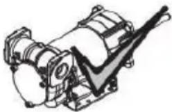
| FOREWORD | -Before carrying out any connection, refer to the visual indications ie arrow on the pump head, to identify suction and delivery |
| WARNING | Wrong connection can cause serious pump damage. |
| PRELIMINARY INSPECTION | Before connection, make sure that the piping and the suction tank are free of dirt and solid residue that could damage the pump and its accessories. NEVER COLLECT THE FLUID FROM THE BOTTOM OF THE TANK SINCEIT MAY CONTAIN IMPURITIES- Before connecting the delivery pipe, partially fill the pump body, from delivery side, with the liquid that needs to be pumped in order to facilitate priming.- Do not use conical threaded fittings, which could damage the threaded inlet or outlet openings of the pump if excessively tightened. |
INITIAL START-UP
| FOREWORD | Check that the quantity of fluid in the suction tank is greater than the amount you wish to transfer.-Makesure that the residual capacity of the delivery tank is greater than the quantity you wish to transfer.-Make sure that the piping and line accessories are in good condition. |
| NOTICE | THIS PUMP IS NOT PROVIDED FOR FURTHER REGULATION OF DELIVERY AND PRESSURE |
| WARNING | Fluid leaks can damage objects and injure persons. |
| NOTICE | -Never start or stop the pump by connecting or cutting out the power supply.-Prolonged contact with some fluidscan damage the skin.The use of goggles and glovesis recommended. |
| IF THE PUMP DOES NOT PRIME | Depending on the system characteristics,the priming phase can last from several seconds to a few minutes.If thisphase is prolonged,stop thepump and verify:-that the pump is not running completelydry (fill with fluid from thedelivery line);-that the suction pipe guarantees against air infiltration;that the suction filter is not clogged;that the suction height is not higher than 2 mt.that all air has been released from the delivery pipe. |
| AT THE END OF THE INITIAL START-UP | When priming has occurred,verify that the pumpis operating within the anticipated range,in particular:-that under conditions of maximum back pressure,the powerabsorption of the motor stays within the values shown on the identification plate;that the delivery back pressure does not exceed the maximum back pressure for the pump |
EVERYDAY USE
USE PROCEDURE
1 Inflexible pipes are used, attach the ends of the piping to the tanks. In the absence of an appropriate slot, solidly grasp the delivery pipe before beginning dispensing.
2 Before starting the pump make sure that the delivery valve is closed (dispensing nozzle or line valve) or make sure that the delivery pipe is properly inserted inside the destination tank.
3 Turn the ON/OFF switch on
4 Open the delivery valve, solidly grasping the pipe
5 While dispensing.do not inhale the pumped product
6 If any treated fluid leaks out during dispensing, take all steps necessary to ensure the leaked fluid is cleaned up and safe as specified on the product technical sheet.
7 Close the delivery valve to stop dispensing and switch off the pump, or switch off the pump and then close the delivery valve
| WARNING |  | THE WORKING OPERATIONS MUST ALWAYS BE GUARDED BY THI OPERATOR. |
| The by-pass valve allows functioning with delivery closed only for short periods (max. 3 minutes) | ||
| To avoid damaging the pump, after use, make sure the pump is off. | ||
| In case of a power break, switch the pump off straight away. | ||
| Should any sealants be used on the suction and delivery circuit of the pump make sure that these products are not released inside the pump. | ||
| Foreign bodies in the suction and delivery circuit of the pump could cause malfunctioning and breakage of the pump components. |
M△INTEN△NCE
Safety instructions The pump is designed and constructed to require a minimum of maintenance. Before carrying out any maintenancework,disconnect the pump from any electrical and hydraulic power source. During maintenance,the use of personal protective equipment (PPE)is compulsory. In any case always bear in mind the following basic recommendationsfor a goodfunctioning of the pump
| WARNING |  | BEFORE ANYOPERATION, ENSURE TO BE OUTOF AREAS FOR SAFETY REASONS IT'S NOTALLOWEDTO PARTS: (1) BOTTOM (2) MOTOR PIPE(3) PUMP BODY | POTENTIALLYEXPLOSIVE DISASSEMBLE THESE | ||||||
| FOR SAFETY REASONS IT IS FORBIDDEN TO REMOVE PLATE" (1), "MOTOR TUBE" (2) AND "FRONT SHIELD" (3). | THE PARTS | "BOTTOM | |||||||
| Authorised maintenance personnel | All maintenance must be performed by qualified personnel.Tampering can lead to performance degradation,danger topersons and/or propertyand may resultin the warranty and UL/ATEXCERTIFICATION being voided. |
| Measures to be taken | Check that the labels and plates found on the dispensing system do not deteriorate or become detachedover time. |
| ONCEAWEEK: | -Check that the pipe connections are not loose to prevent any leaks;-Check and keep the filter installed on the suction line clean. |
| ONCE A MONTH: | -Check the pump body and keep it clean and free of any impurities;-Check that the electrical supply cables are in good condition. |
NOISE LEVEL
Under normal operating conditions, noise emission of all models does not exceed 74dB at a distance of 1 metre from the electric pump.
PROBLEMS AND SOLUTIONS
For any problems contact the authorised dealer nearest to you.
| PROBLEM | POSSIBLE CAUSE | CORRECTIVE ACTION |
| THEMOTOR IS NOT TURNING | Lackof electric power | Check the electrical connections and the satety systems |
| Rotor jammed | Check for possible damage or obstruction of the rotating components. | |
| Motor problems | Contact the Service Department | |
| THE MOTOR TURNS SLOWLY WHEN STARTING | Low voltage in the electric power line | Bring the voltage back within the anticipated limits |
| LOWOR NO FLOWRATE | Low level in the suction tank | Refill the tank |
| Foot valve blocked | Clean and/or replace the valve | |
| Filter clogged | Clean the filter | |
| Excessive suction pressure | Lower the pump with respect to the level of the tank or increase the cross-section of the piping | |
| High loss of head in the delivery circuit (working with the by-pass open) | Use shorter piping or of greater diameter | |
| By-pass valve blocked | Dismantle the valve, clean and/or replace it | |
| Air entering the pump or the suction piping | Check the seals of the connections | |
| A narrowing in the suction piping | Use piping suitable for working under suction pressure | |
| Low rotation speed | Check the voltage at the pump. Adjust the voltage and/or use cables of greater cross-section | |
| The suction piping is resting on the bottom of the tank | Raise the piping | |
| INCREASED PUMP NOISE | Cavitation occurring | Reduce suction pressure |
| Irregularfunctioning of the by-pass | Dispense until the air is purged from the bypass system | |
| Presence of air in the fluid | Verify the suction connections | |
| LEAKAGE FROM THE PUMP BODY | Seal damaged | Check and replace the seal |
| THE PUMP DOES NOT PRIME THE LIQUID | Suction circuit blocked | Remove the blockage from the suction circuit |
| Malfunction of foot valve fitted on suction circuit | Replace foot valve | |
| The suction chambers are dry | Add liquid from pump delivery side | |
| The pump chambers are dirty or blocked | Remove the blockages from the suction and delivery valves | |
| THE HEAT SENSOR ACTIVATES UNDER NORMAL OPERATING CONDITIONS | Operating fault | Contact the technical support |
DEMOLITION AND DISPOSAL
Foreword
Disposing of packing materials Metal Parts Disposal Disposal of electric and electronic components

Information regarding the environment for clients residing within the European Union
Miscellaneous parts disposal
If the system needs to be disposed, the parts which make it up must be delivered to companies that specialize in the recycling and disposal of industrial waste and, in particular: The packaging consists of biodegradable cardboard which can be delivered to companies for normal recycling of cellulose.
Metal parts, whether paint-finished or in stainless steel, can be consigned to scrap metal collectors. These must be disposed of by companies that specialize in the disposal of electronic components, in accordance with the indications of directive 2012/19/UE (see text of directive below).
European Directive 2012/19/UE requires that all equipment marked with this symbol on the product and/or packaging not be disposed of together with non-differentiated urban waste. The symbol indicates that this product must not be disposed of together with normal household waste. It is the responsibility of the owner to dispose of these products as well as other electric or electronic equipment by means of the specific refuse collection structures indicated by the government or the local governing authorities.
Disposing of RAEE equipment as household wastes is strictly forbidden. Such wastes must be disposed of separately.
Any hazardous substances in the electrical and electronic appliances and/or the misuse of such appliances can have potentially serious consequences for the environment and human health.
In case of the unlawful disposal of said wastes, fines will be applicable as defined by the laws in force.
Other components, such as pipes, rubber gaskets, plastic parts and wires, must be disposed of by companies specialising in the disposal of industrial waste.
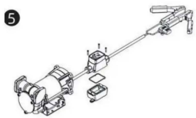
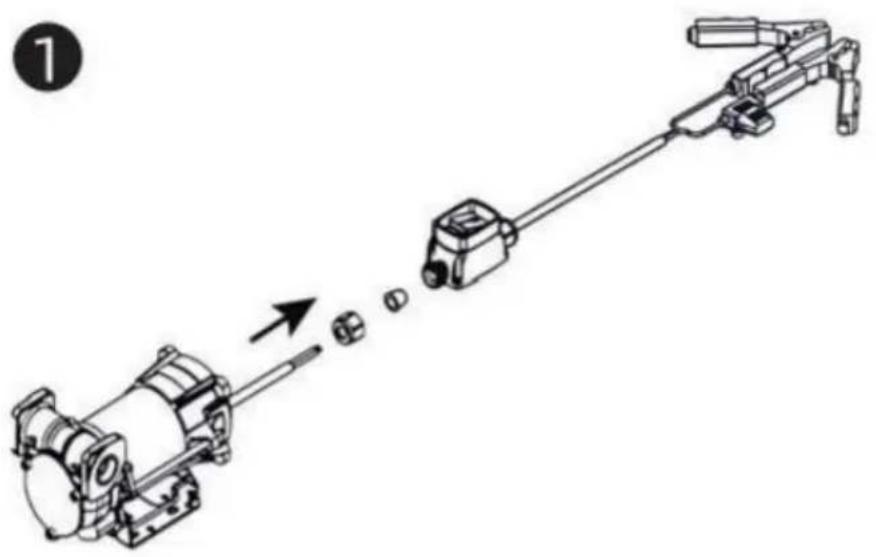
CASE SWITCH WITH PLIERSFOR THE PUMP OF FUELTANK

THESWTCH HAS NOT BEEN DESIGNED IN COMPLIANCE WITH ATEX REGULATION OR TO OPERATE IN ENVIRONMENTS WITH POTENTIALLY EXPLOSIVE ATMOSPHERE.
DO NOT INSTALL IN POTENTIALLY EXPLOSIVE LOCATIONS.

natural_image
Diagram of a mechanical assembly with an arrow indicating motion, showing a motor, gear, and shaft (no text or labels)
natural_image
Technical line drawing of a mechanical assembly with no visible text or symbols
natural_image
Technical line drawing of a mechanical assembly with no visible text or symbols
t is preferable to place Case Switch with pliers sheltered from atmospheric agents.
ts installation must be carried out by specialized personnel and carried out according to the instructions provided in this document

natural_image
Technical line drawing of a mechanical assembly with motor, gears, and housing (no text or symbols)
natural_image
Technical line drawing of a mechanical device with a thumbs-up icon (no text or symbols on the diagram itself)
DANGER!
Fumes accumulated whilefueling create an Explosive Atmosphere. It is CRITICAL that all possible sources of ignition be removed to a safe distance or extinguished. Sources of ignition would include (but not be limited to) open flames, cigarettes, static discharge, or electrical connection that can create a spark. Explosion, fire, and severe injury or death will occur if the explosive vapors are ignited.
Fumes accumulated whilefueling create an explosive Atmosphere around the tank that is beingfiled Toavoidpossible explosion of accumulated vapors, it is critical to keep possible sources of spark/ignition at safe distances from the fuelvapors
The accompanying diagram shows minimum safe distances for safe fueling 3m is the minimum safe distance between.
-Power source, switch and fuel supply.
-Power source, switch and thank being filled.
-Power source, switch and pump.

flowchart
graph TD
    A["PUMP INLET SIDE TANK"] --> B["POWER CORD"]
    B --> C["SWITCH"]
    C --> D["FUSE 25A"]
    E["SIDE TANK"] --> F["2.5M MIN."]
    F --> G["3M MIN."]
    H["Ground"] --> I["+ -"]
WARNING
●STATIC EL ECTRIC SPARK EXPLOSION HAZARD
● NEVER fill portable containers that are in oron vehicl

natural_image
Symbolic icon depicting a person using a tool to lift a vehicle, enclosed in a circle with radiating lines (no text or symbols)● ALWAYS PLACE CONTAINERS ON GROUND
- Keep nozzle in contact with container while flli

Astatic electric sparkcanoccur when fling portable containers sitting ontruck bed liners, or on any vehicle' scarpeting orfloor mating. This spark will explosively ignite gasoline vapor hire and cause SERIOUSINJURY or DEATH
FCC Information:
CAUTION: Changes or modifications not expressly approved by the party responsible for compliance could void the user's authority to operate the equipment!
This device complies with Part 15 of the FCC Rules.Operation is subject the following two conditions:
1) This product may cause harmful interference.
2) This product must accept any interference received, including interference that may cause undesired operation.
WARNING: Changes or modifications to this product not expressly approved by the party. Responsible for compliance could void the user's authority to operate the product.
Note: This product has been tested and found to comply with the limits for B digital device pursuant to Part 15 of the FCC Rules. These limits are designed to provide reasonable protection against harmful interference in a residential installation.
This product generates, uses and can radiate radio frequency energy, and if not installed and used in accordance with the instructions, it may cause harmful interference to radio communications. However, there is no guarantee that interference will not occur in a particular installation. If this product does cause harmful interference to radio or television reception, which can be determined by turning the product off and on, the user is encouraged to try to correct the interference by one or more of the following measures.
- Reorient or relocate the receiving antenna.
·Increase the distance between the product and receiver.
- Connect the product to an outlet on a circuit different from that to which the receiver is connected.
- Consult the dealer or an experienced radio/TV technician for assistance.
CORRECT DISPOSAL
This product is subject to the provision of European Directive 2012/19/EU. The symbol showing a wheelie bin crossed through indicates that the product requires separate refuse collection in the European Union. This applies to the product and all accessories marked with this symbol. Products marked as such may not be discarded with normal domestic waste, but must be taken to a collection point for recycling electrical an electronic devices.
Manufacturer: Shanghaimuxinmuyeyouxiangongsi
Address: Shuangchenglu 803nong11hao1602A-1609shi, baoshanqu, shanghai 200000 CN.
Imported to AUS: SIHAO PTY LTD. 1 ROKEVA STREETEASTWOOD NSW 2122 Australia
Imported to USA: Sanven Technology Ltd. Suite 250, 9166 Anaheim Place, Rancho Cucamonga, CA 91730
| UK | REP |
YH CONSULTING LIMITED. C/O YH Consulting Limited Office 147, Centurion House, London Road, Staines-upon-Thames, Surrey, TW18 4AX
| EC | REP |
Technical Support and E-Warranty Certificate www.vevor.com/support
VEVOR
Affordable. Reliable. Home Improvement.
PORTABLE RÉSERVOIR DIESEL ET ESSENCE
MODÈLE: YDIES200L-E / YDIES400L-E
Affordable. Reliable. Home Improvement.
PORTABLE DIESEI GASOLINE TAN
MODÈLE: YDIES200L-E / YDIES400L-E

natural_image
Two identical gray industrial electrical enclosures with visible wiring and components, no text or symbols present.Operation and Installation
PRÉPARATION LE TRANSFERT UNITÉ POUR OPÉRATION;
natural_image
Mechanical assembly diagram showing a motor and gear mechanism (no text or labels)ZONE 0
ZONE 20
ZONE 21

natural_image
Pure mechanical assembly diagram without any text, numbers, or symbolsINTENDED USE
| INTENDED USE | | PUMP FOR TRANSFERRING FUEL SUITABLE FOR OPERATING IN ZONESCLASSIFIED“1”AND “2”, ACCORDING TO DIRECTIVE 99/92/CE |
| THE DETERMINATION OF THE AREAS (ZONES) IS TO BE CARRIED OUT BY THE USER |
| FORBIDDEN USE | Using the appliance for fluids other than those listed at paragraph “Fluids permitted” and for uses other than those described at the item “authorised use” is forbidden. |
| PLANT OPERATION RESTRICTIONS IT IS FORBIDDEN: | |
| 1 | To use the appliance in a construction configuration other than that contemplated by the manufacturer |
| 2 | To use the appliance with fixed guards tampered with or removed. |
| 3 | To use the appliance in places where there is risk of explosion and/or fires classified in the following zones: 0; 20; 21; 22 |
| 4 | To integrate other systems and/or equipment not considered by the manufacturer in the executive project. |
| 5 | To connect the appliance up to energy sources other than those contemplated by the manufacturer |
| 6 | To use the commercial devices for purposes other than those indicated by the manufacturer. |
| 7 | To use in case of lightnings |
WARNING

INSTALL AWAY FROM STRONG ELECTROMAGNETIC FIELDS
HANDLING AND TRANSPORT
Due to the limited weight and dimensions of the pumps, special lifting equipment is not required to handle them. The pumps are carefully packed before dispatch. Check the packing when receiving the material and store in a dry place.
GENERAL WARNINGS
| Important precautions | To ensure operator safety and to protect the pump from potential damage, workers must be fully acquainted with this instruction manual before performing any operation. |
| Symbols used in the manual | The following symbols will be used throughout the manual to highlight safety information and precautions of particular importance: |

WARNING
WARNING indicates a hazardous situation which, if not avoided, could result in death or serious injury

NOTICE
NOTICE is used to address pratices not related to personal injury
Manual preservation
This manual should be complete and legible throughout. It should remain available to end users and specialist installation and maintenance technicians for consultation at any time.
| NOTICE | | ALWAYS USETHE RIGHT VOLTAGES TO CONNECTTHE PUMPS |
| WARNING | | BEFORE PROCEEDING WITH THE REFUELLING OF AIRCRAFTS, ENSURE THAT THE SYSTEM INTENDED FOR SUCH ACTION COMPLIES WITH THE REGULATIONS IN FORCE IN THE COUNTRYOF USE |
| WARNING | | USE THE PUMP ONLYWITH EFLUIDS PERMITTEDDO NOT USE WITHFLUIDS NOT PERMITTED TOAVOID DAMAGING THE PUMP THE WARRANTYLAPSES IN CASE OF MISUSE OF THE FLUID. |
| DO NOT USE THE PUMP WITH LIQUID FOOD PRODUCTS AND/OR WATER-BASED FLUIDS. | ||
| DO NOT OPERATE THE PUMPDRYTO AVOID DAMAGE. | ||
| Before connection, make sure that the piping and the suction tank are free of dirt and solid residue that could damage the pump and its accessories. NEVER COLLECT THE FLUID FROM THE BOTTOM OF THE TANK SINCE IT MAY CONTAIN IMPURITIES | ||
| Keep a working fire extinguisher in the work area. | ||
| Do not operate the unit when fatigued or under the influence of drugs or alcohol. | ||
| Do not alter or modify equipment. Alterations or modifications may void agency approvals and create safety hazards | ||
| Keep children and animals away from work area. | ||
| Comply with all applicable safety regulations.Do not use in case of lightnings |

BEFORE USING THE PUMP SWITCH OFF ALL THE ELECTRONIC DEVICES(I.E. MOBILE PHONES,BEEPERS ETC.)
FIRST AID RULES
Contact with the product
Persons who have suffered electric shock
In the event of problems developing following EYE/SKIN CONTACT, INHALATION or INGESTION of the treated product, please refer to the SAFETY DATA SHEET of the fluid handled.
Disconnect the power source, or use adry insulator to protect yourself while you move the injured person away from any electrical conductor. Avoid touching the injured person with your bare hands until he is far away from any conductor. Immediately call or help from qualified and trained personnel. Do not operate switches with wet hands.
NOTICE

SMOKING PROHIBITED
Please refer to the safety data sheet for the product

GENERAL SAFETY RULES
USER'S RESPONSIBILITY
IT IS ESSENTIAL TO GET TO KNOW AND UNDERSTAND THE INFORMATION CONTAINED IN THIS MANUAL.
IT IS ESSENTIAL TO GET TO KNOW AND OBSERVE THE SAFETY SPECIFICATIONS FOR FLAMMABLE LIQUIDS.
BEFORE USING THE PUMP IT'S IMPORTANT TO TRAIN OPERATORS, INSTALLERS AND MAINTENANCE STAFF TO LETTHEM WORKINAPARTICULARAREA NO. 1AS MENTIONED BY DIRECTIVE 99/92/EC
| Essential protective equipment characteristics | In case of contact with theproduct and for good standard of behaviour,wear protective equipmentwhich is: .Suited to the operations that need to be performed .Resistant to products used To do so,please refer to the relevant technical datasheets of the fuid used. | ||
| Personal protective equipment that must be worn | | | |
| safety shoes | close-fiting | dofthing | |
| | ||
| protection gloves | safety goggles | ||
| Necessary safety devices | | instructions manual | |
| Protective gloves | Prolonged contact with the treated product may cause skin irritation;always wear protective gloves during dispensing. | ||
| WARNING | ENFORCE REGULATIONS FOR ELECTRICAL INSTALLATIONALL WIRING AND ELECTRICAL CONNECTIONS MUST BE PERFORMED BY AUTHORIZED AND SUITABLY TRAINED PERSONNEL.Never touch the electric plug or socket with wet hands.Do not switch the dispensing system on if the network connection cable or important parts of the apparatus are damaged,such as the inlet/outlet pipe, nozzle or safety devices.Replace the damaged pipe immediately. | ||
| WARNING | The electrical connection between the plug and socket must be kept well away from waterTHE PUMP IS EQUIPPED WITH CURRENT-SENSING PROTECTION. IF IT ACTIVATES TURN OFF THE PUMP IMMEDIATELY.THE PUMP IS EQUIPPED WITH PROTECTION AGAINST OVERHEATING AND OVERLOAD RISKS. SHOULD SUCH DEVICES ACTIVATE, THE PUMP SHUTS DOWN AUTOMATICALLY, BUT THE MASTER SWITCH IS NOTTURNED OFF.IT IS IMPORTANT TO STOP THE PUMP USING ITS SWITCH. THE PUMP RESTARTS AFTER ITS NORMAL OPERATING CONDITIONS HAVE BEEN RESTORED. | ||
| WARNING | FAILURE TO OBSERVE THE ABOVE MENTIONED RULES CAN CAUSE SERIOUS ACCIDENTSSHOULD THE HEAT SENSOR ACTIVATE UNDER NORMAL USE CONDITIONS, PLEASE CONTACT THE TECHNICALSUPPORT | ||
| NOTICE | TO PREVENT ELECTRIC SHOCK AND DETONATION OF SPARKS, ALL PUMPING SYSTEM MUST HAVE PROPER GROUNDING, INCLUDING TANK AND ANY ACCESSORIES | ||
TECHNICAL DATA PERFORMANCE SPECIFICATIONS
The performance diagram shows flow rate as a function of back pressure.
| Absorption (A) | FlowRate (/min)-(gpm) | Back Pressure (bar)-(psi) | ||
| Functioning Point | ||||
| A = (Maximum Flow Rate) | 15 | 35-9 | 0,2 -3 | |
| C • (By-Pass) | 25 | 0 | 1] 6 | |
| ATTENTION | The curve refers to the following operating conditions:Fluid: PETROL,Temperature: 20°C Suction conditions: The pipe and the pump position relative to the fluid level is such that a low pressure of O.3 bar is generated at the nominal flow rate.Under different suction conditions higher low pressure values can be created that reduce the flow rate compared to the same back pressure values. To obtain the best performance, it is very important to reduce loss of suction pressure as much as possible by following these instructions:· shorten the suction pipe as much as possible· avoid useless elbows or throttling in the pipes· keep the suction filter clean· use a pipe with a diameter equal to, or greater than, indicated (see Installation). | |||
OPERATING CONDITIONS
ENVIRONMENTAL CONDITIONS
| AMBIENTTEMPERATUREFLUIDTEMPERATURERELATIVEHUMIDITY | min.+23°F/max+104°Fmin.-10°C/max+40C | |
| min.+23°F/max+104°Fmin.-10C7max+40C | ||
| max.90% | ||
| WARNING | | The temperature limits shown apply to the pump components and must be respected to avoid possible damage or malfunction. |
ELECTRICAL POWER SUPPLY
| NOTICE | | The pump must be powered by DC line, the nominal values of which are indicated on the table in the paragraph "ELECTRICAL DATA"The maximum acceptable variations from the electrical parametersare:Voltage:+/-5%of the EX30 nominal value+/-10%of the EX20 nominal valueFrequency:+/-2%of the nominal value |
| WARNING | | Power supply from lines with values that do not fall within the indicated limits could cause damage to the electrical and electronic components. |
DUTY CYCLE
| NOTICE | | In conditions of maximum T.Environment( 40^ c)and at the nominal transfer conditions:-The EX30 pumps have been designed for intermittent use and a 30 min duty cycle.ONand 60 min OFF-The EX20 pumps have been designed for operating conditions S1 |
| WARNING | | Functioning under by-passconditions is only allowed for short periods of time (max. 30 seconds). |
FLUIDS PERMITTED
| WARNING | | THE PUMP CAN BE USED -DIESEL -KEROSENE -PETROL -AVGAS -PETROLALCOHOL 100/100LL (pump) | ONLYWITH THE FOLLOWING FLUIDS: | |||
| MIXED MAX15% only)-JETA/A1 (pump only) | ||||||
| -ASPEN2/4 | ||||||
INSTALLATION
| WARNING | | BEFOREANYOPERATION, ENSURE TO BE OUT OFPOTENTIALLYEXPLOSIVE AREAS |
| The pump must never be operated before the delivery and suction lines have been connected |
PRELIMINARY -Verify that all components are present. Request any missing parts from the manufacturer INSPECTION -Check that the pump has not suffered any damageduringtransport or storage.
-Carefullyclean the suction and delivery inlets and outlets, removing any dust or other packaging material that may be present.
Check that the electrical data corresponds to those indicated on the data plate
-Always install in anilluminated area.
Install the pump at a height of min. 80 cm
| WARNING | | IF VALVES IN THE CIRCUIT ARE TO BE INSTALLED,MAKE SURE THEY ARE EQUIPPED WITH OVERPRESSURE SYSTEM. | ||||||||
| CLEAN | THE | TANK | AND | MAKE | SURE | IT | IS | WELL- | ||
| VENTILATED (RECOMMENDED) | OPENING | PRESSURE:3psi | ||||||||
| WARNING | | DO NOT BLOCK THE DRAINAGE HOLES | ||||||||
POSITIONING, CONFIGURATIONS AND ACCESSORIES
| NOTICE | | The pump must be secured in a stable manner. |
| WARNING | | It is the installer's responsibility to provide the line accessories necessary for the safe and proper functioning of the pump. The accessories that are not suitable to be used with the previously indicated material could damage the pump and/or cause injury to persons, as well as causing pollution. |
| To maximise performance and prevent damage that could affect pump operation, always demand original accessories. | ||
NOTES ONSUCTIONAND DELIVERY LINES
DELIVERY
The selection of the pump model must be made taking into account the characteristics of the system
The combination OF:thelength of the pipe,the diameter of thepipe,as well as the accessories installed, could create back pressure that are greater than the maximum predicted pressure,thereby causing the pump's electronic controls to intervene and reducing the dispensed flow considerably.
In these cases, to guarantee correct operation of the pump, it is necessary to reduce the resistance of the system using pipes that are shorter or that have a greater diameter, as well as line accessories with smaller resistances (e.g. an automatic dispensing nozzle with greater flow rate capacity)
SUCTION
Self-priming pumps are characterized by excellent suction capacity.
During the start-up phase, when the suction pipe is empty and the pump is wet with the fluid, the electric pump unit is able to suck liquid from a maximum vertical distance of 2m
It is important to note that it could take up to 1 minute for the pump to prime and that the presence of an automatic dispensing nozzle on the delivery side will prevent the air trapped during the installation from being released and, therefore, the correct priming of the pump. For this reason, it is always advisable to prime the pump without an automatic delivery nozzle, verifying the proper wetting of the pump
Always install a foot valve to prevent the suction pipe from being emptied and to keep the pump wet at all times In this way, the pump will always start up immediately the next times it is used. When the system is in operation, the pump can operate with back pressures of up to 05 bars on the suction inlet; beyond this point, the pump may begin to cavitate resulting in a drop of the flow rate and an increase in the noise levels of the system.
In light of this, it is important to guarantee small back pressures on the suction side, by using short pipes with diameters that are equal to or larger than those recommended, reducing bends to a minimum, and using filters with a large cross-section and foot valves with minimum possible resistance on the suction side. It is very important to keep the suction filters clean because, when they become clogged, they increase the resistance of the system
The vertical distance between the pump and the fluid must be kept as short as possible, and it must fall within the 2m maximum required for priming. If the distance is greater, a foot valve must be installed to allow the suction pipes to fill up and the diameter pipes must be larger. It is however recommended that pump not be installed if the vertical distance is greater than 3m.
| WARNING | If the suction tank is higher than the pump, an anti-siphon valve should be installed to prevent accidental diesel fuel leaks. Dimension the installation in order to controlthebackpressures due towater hammering |
| It is a good system practice to install vacuum and air pressure gauges right at the inlets and outlets of the pump, which allow verification that operating conditions are within anticipated limits. To prevent the suction pipes frombeing emptied when the pump stops, a foot valve should be installed. | |
| THE INSTALLER IS RECOMMENDED TO INSTALLASUCTION FILTER. | |
CONNECTIONS
ELECTRICAL CONNECTIONS
| WARNING | | BEFORE ANYOPERATION, ENSURE TO BE OUT OF POTENTIALLYEXPLOSIVE AREAS |
| IT IS THE INSTALLER'S RESPONSIBILITY TO CARRY OUT THE ELECTRICAL CONNECTIONS IN COMPLIANCE WITH THE RELEVANT STANDARDS. | ||
| NOTICE | | BLACK CABLE: “■” (negative pole)RED CABLE: “+” (positive pole) |
| WARNING |  | DO NOT CUT THE CABLE FOR ANY REASON |
| WARNING |  | Comply with the following (not exhaustive)instructions to ensure a proper electrical connection: |
During installation and maintenance make sure that power supply to the electric lines has been turned off. -Use cables with minimum sections, rated voltages and installation type that are suitable for the characteristics indicated in paragraph "ELECTRICAL DATA" and the installation environme nt. -Always make sure that the cover of the terminalstrip box is closed before switching on the power supply, after having checked the integrity of the seal gaskets that ensure the IP55 protection grade. For those screws use a 10 nm clamping couple
| WARNING |  | All motors are equipped with a grounding terminal.Make sure all the plantis properly grounded. |
| NOTICE |  | IN THE EVENT OF INSTALLATION IN ZONES WHICH ARE NOT CLASSIFIED, ITIS SUFFICIENT TO OBSERVE THE MINIMUM SAFETY STANDARDS ALREADYMENTIONED IN THIS MANUAL. |
| WARNING |  | -THE OWNER HAS THE RESPONSIBILITY TO VERIFY THAT ALL THE LOCALAND NATIONAL REGULATIONS HAVEBEEN OBSERVED.-MAKE SURE THAT THE CABLE CONNECTING THE BATTERY IS PROTECTEDFROM HEAT SOURCES AND SHARP EDGES. INSTALL THE FUSE CLOsertoTHE BATTERY. |
| WARNING |  | FAILURE TO OBSERVE THE ABOVE MENTIONED RULES CAN CAUSE SERIOUSACCIDENTS |
| WARNING |  | IN CASE THE ELECTRICAL CABLING IS IN CLASSIFIED AREA, A CABLINGWITH PROTECTION DEGREESUITABLE TO THE WORKING AREA SHOULD BEPERFORMED. |
| WARNING |  | PREVENT THE INSTALLATION OF ASTOP BUTTON INA REACHABLE POSITIONANDWITHADEGREEOFPROTECTIONSUITABLEFOR THE CLASSIFICATIONOFTHE PUMP ONWHICH ITIS INSTALLED. |
PIPING CONNECTIONS
| FOREWORD | -Before carrying out any connection, refer to the visual indications ie arrow on the pump head, to identify suction and delivery |
| WARNING | Wrong connection can cause serious pump damage. |
| PRELIMINARY INSPECTION | Before connection, make sure that the piping and the suction tank are free of dirt and solid residue that could damage the pump and its accessories. NEVER COLLECT THE FLUID FROM THE BOTTOM OF THE TANK SINCEIT MAY CONTAIN IMPURITIES- Before connecting the delivery pipe, partially fill the pump body, from delivery side, with the liquid that needs to be pumped in order to facilitate priming.- Do not use conical threaded fittings, which could damage the threaded inlet or outlet openings of the pump if excessively tightened. |
INITIAL START-UP
| FOREWORD | Check that the quantity of fluid in the suction tank is greater than the amount you wish to transfer.-Makesure that the residual capacity of the delivery tank is greater than the quantity you wish to transfer.-Make sure that the piping and line accessories are in good condition. |
| NOTICE | THIS PUMP IS NOT PROVIDED FOR FURTHER REGULATION OF DELIVERY AND PRESSURE |
| WARNING | Fluid leaks can damage objects and injure persons. |
| NOTICE | -Never start or stop the pump by connecting or cutting out the power supply.-Prolonged contact with some fluidscan damage the skin.The use of goggles and glovesis recommended. |
| IF THE PUMP DOES NOT PRIME | Depending on the system characteristics,the priming phase can last from several seconds to a few minutes.If thisphase is prolonged,stop thepump and verify:-that the pump is not running completelydry (fill with fluid from thedelivery line);-that the suction pipe guarantees against air infiltration;that the suction filter is not clogged;that the suction height is not higher than 2 mt.that all air has been released from the delivery pipe. |
| AT THE END OF THE INITIAL START-UP | When priming has occurred,verify that the pumpis operating within the anticipated range,in particular:-that under conditions of maximum back pressure,the powerabsorption of the motor stays within the values shown on the identification plate;that the delivery back pressure does not exceed the maximum back pressure for the pump |
EVERYDAY USE
USE PROCEDURE
1 Inflexible pipes are used, attach the ends of the piping to the tanks. In the absence of an appropriate slot, solidly grasp the delivery pipe before beginning dispensing.
2 Before starting the pump make sure that the delivery valve is closed (dispensing nozzle or line valve) or make sure that the delivery pipe is properly inserted inside the destination tank.
3 Turn the ON/OFF switch on
4 Open the delivery valve, solidly grasping the pipe
5 While dispensing.do not inhale the pumped product
6 If any treated fluid leaks out during dispensing, take all steps necessary to ensure the leaked fluid is cleaned up and safe as specified on the product technical sheet.
7 Close the delivery valve to stop dispensing and switch off the pump, or switch off the pump and then close the delivery valve
| WARNING | | THE WORKING OPERATIONS MUST ALWAYS BE GUARDED BY THI OPERATOR. |
| The by-pass valve allows functioning with delivery closed only for short periods (max. 3 minutes) | ||
| To avoid damaging the pump, after use, make sure the pump is off. | ||
| In case of a power break, switch the pump off straight away. | ||
| Should any sealants be used on the suction and delivery circuit of the pump make sure that these products are not released inside the pump. | ||
| Foreign bodies in the suction and delivery circuit of the pump could cause malfunctioning and breakage of the pump components. |
M△INTEN△NCE
Safety instructions The pump is designed and constructed to require a minimum of maintenance. Before carrying out any maintenancework,disconnect the pump from any electrical and hydraulic power source. During maintenance,the use of personal protective equipment (PPE)is compulsory. In any case always bear in mind the following basic recommendationsfor a goodfunctioning of the pump
| WARNING | | BEFORE ANYOPERATION, ENSURE TO BE OUTOF AREAS FOR SAFETY REASONS IT'S NOTALLOWEDTO PARTS: (1) BOTTOM (2) MOTOR PIPE(3) PUMP BODY | POTENTIALLYEXPLOSIVE DISASSEMBLE THESE | ||||||
| FOR SAFETY REASONS IT IS FORBIDDEN TO REMOVE PLATE" (1), "MOTOR TUBE" (2) AND "FRONT SHIELD" (3). | THE PARTS | "BOTTOM | |||||||
| Authorised maintenance personnel | All maintenance must be performed by qualified personnel.Tampering can lead to performance degradation,danger topersons and/or propertyand may resultin the warranty and UL/ATEXCERTIFICATION being voided. |
| Measures to be taken | Check that the labels and plates found on the dispensing system do not deteriorate or become detachedover time. |
| ONCEAWEEK: | -Check that the pipe connections are not loose to prevent any leaks;-Check and keep the filter installed on the suction line clean. |
| ONCE A MONTH: | -Check the pump body and keep it clean and free of any impurities;-Check that the electrical supply cables are in good condition. |
NOISE LEVEL
Under normal operating conditions, noise emission of all models does not exceed 74dB at a distance of 1 metre from the electric pump.
PROBLEMS AND SOLUTIONS
For any problems contact the authorised dealer nearest to you.
| PROBLEM | POSSIBLE CAUSE | CORRECTIVE ACTION |
| THEMOTOR IS NOT TURNING | Lackof electric power | Check the electrical connections and the satety systems |
| Rotor jammed | Check for possible damage or obstruction of the rotating components. | |
| Motor problems | Contact the Service Department | |
| THE MOTOR TURNS SLOWLY WHEN STARTING | Low voltage in the electric power line | Bring the voltage back within the anticipated limits |
| LOWOR NO FLOWRATE | Low level in the suction tank | Refill the tank |
| Foot valve blocked | Clean and/or replace the valve | |
| Filter clogged | Clean the filter | |
| Excessive suction pressure | Lower the pump with respect to the level of the tank or increase the cross-section of the piping | |
| High loss of head in the delivery circuit (working with the by-pass open) | Use shorter piping or of greater diameter | |
| By-pass valve blocked | Dismantle the valve, clean and/or replace it | |
| Air entering the pump or the suction piping | Check the seals of the connections | |
| A narrowing in the suction piping | Use piping suitable for working under suction pressure | |
| Low rotation speed | Check the voltage at the pump. Adjust the voltage and/or use cables of greater cross-section | |
| The suction piping is resting on the bottom of the tank | Raise the piping | |
| INCREASED PUMP NOISE | Cavitation occurring | Reduce suction pressure |
| Irregularfunctioning of the by-pass | Dispense until the air is purged from the bypass system | |
| Presence of air in the fluid | Verify the suction connections | |
| LEAKAGE FROM THE PUMP BODY | Seal damaged | Check and replace the seal |
| THE PUMP DOES NOT PRIME THE LIQUID | Suction circuit blocked | Remove the blockage from the suction circuit |
| Malfunction of foot valve fitted on suction circuit | Replace foot valve | |
| The suction chambers are dry | Add liquid from pump delivery side | |
| The pump chambers are dirty or blocked | Remove the blockages from the suction and delivery valves | |
| THE HEAT SENSOR ACTIVATES UNDER NORMAL OPERATING CONDITIONS | Operating fault | Contact the technical support |
DEMOLITION AND DISPOSAL
Foreword
Disposing of packing materials Metal Parts Disposal Disposal of electric and electronic components

Information regarding the environment for clients residing within the European Union
Miscellaneous parts disposal
If the system needs to be disposed, the parts which make it up must be delivered to companies that specialize in the recycling and disposal of industrial waste and, in particular: The packaging consists of biodegradable cardboard which can be delivered to companies for normal recycling of cellulose.
Metal parts, whether paint-finished or in stainless steel, can be consigned to scrap metal collectors. These must be disposed of by companies that specialize in the disposal of electronic components, in accordance with the indications of directive 2012/19/UE (see text of directive below).
European Directive 2012/19/UE requires that all equipment marked with this symbol on the product and/or packaging not be disposed of together with non-differentiated urban waste. The symbol indicates that this product must not be disposed of together with normal household waste. It is the responsibility of the owner to dispose of these products as well as other electric or electronic equipment by means of the specific refuse collection structures indicated by the government or the local governing authorities.
Disposing of RAEE equipment as household wastes is strictly forbidden. Such wastes must be disposed of separately.
Any hazardous substances in the electrical and electronic appliances and/or the misuse of such appliances can have potentially serious consequences for the environment and human health.
In case of the unlawful disposal of said wastes, fines will be applicable as defined by the laws in force.
Other components, such as pipes, rubber gaskets, plastic parts and wires, must be disposed of by companies specialising in the disposal of industrial waste.
INTERRUPTEUR DE BOÎTIER AVEC PINCE POUR LA POMPE DU RÉSERVOIR DE CARBURANT

THESWTCH HAS NOT BEEN DESIGNED IN COMPLIANCE WITH ATEX REGULATION OR TO OPERATE IN ENVIRONMENTS WITH POTENTIALLY EXPLOSIVE ATMOSPHERE.
DO NOT INSTALL IN POTENTIALLY EXPLOSIVE LOCATIONS.

natural_image
Technical line drawing of a mechanical assembly with no visible text or symbols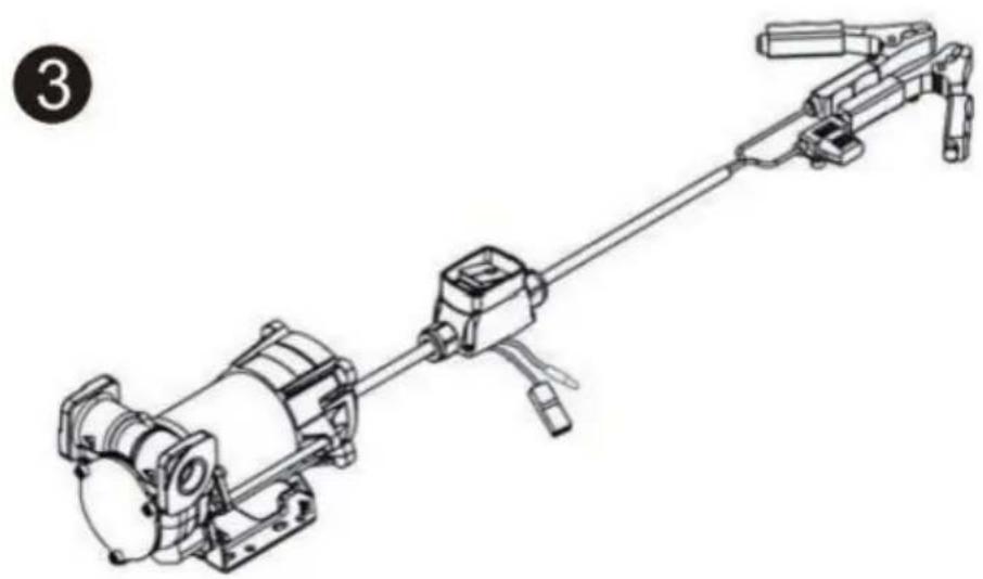
natural_image
Technical line drawing of a mechanical device with no visible text or symbols
t is preferable to place Case Switch with pliers sheltered from atmospheric agents.
ts installation must be carried out by specialized personnel and carried out according to the instructions provided in this document


natural_image
Technical line drawing of a mechanical assembly with motor, gears, and housing (no text or symbols)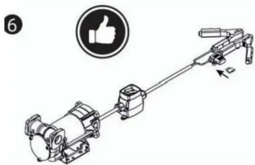
natural_image
Technical line drawing of a mechanical device with a thumbs-up icon (no text or symbols on the diagram itself)
DANGER!
Fumes accumulated whilefueling create an Explosive Atmosphere. It is CRITICAL that all possible sources of ignition be removed to a safe distance or extinguished. Sources of ignition would include (but not be limited to) open flames, cigarettes, static discharge, or electrical connection that can create a spark. Explosion, fire, and severe injury or death will occur if the explosive vapors are ignited.
Fumes accumulated whilefueling create an explosive Atmosphere around the tank that is beingfiled Toavoidpossible explosion of accumulated vapors, it is critical to keep possible sources of spark/ignition at safe distances from the fuelvapors
The accompanying diagram shows minimum safe distances for safe fueling 3m is the minimum safe distance between.
-Power source, switch and fuel supply.
-Power source, switch and thank being filled.
-Power source, switch and pump.

flowchart
graph TD
    A["PUMP INLET SIDE TANK"] --> B["POWER CORD"]
    B --> C["SWITCH"]
    C --> D["FUSE 25A"]
    E["SIDE TANK"] --> F["2.5M MIN."]
    F --> G["3M MIN."]
    G --> H["Ground"]
WARNING
●STATIC EL ECTRIC SPARK EXPLOSION HAZARD
● NEVER fill portable containers that are in oron vehicl

natural_image
Symbolic icon depicting a person using a tool to lift a vehicle, enclosed in a circle with radiating lines (no text or symbols)● ALWAYS PLACE CONTAINERS ON GROUND
- Keep nozzle in contact with container while flli

Astatic electric sparkcanoccur when fling portable containers sitting ontruck bed liners, or on any vehicle' scarpeting orfloor mating- This spark will explosively ignite gasoline vapor hire and cause SERIOUSINJURY or DEATH
FCC Information:
YH CONSULTING LIMITED. C/O YH Consulting Limited Office 147, Centurion House, London Road, Staines-upon-Thames, Surrey, TW18 4AX
| EC | REP |
Affordable. Reliable. Home Improvement.
TRAGBAR DIESEL- UND BENZINTANK
MODELL: YDIES200L-E / YDIES400L-E
www.vevor.com/support
VEVOR
Affordable. Reliable. Home Improvement.
PORTABLE DIESEI GASOLINE TAN
MODELL: YDIES200L-E / YDIES400L-E

natural_image
Two identical gray industrial electrical enclosures with visible wiring and components, no text or symbols present.Foto als Referenz
Operation and Installation
natural_image
Mechanical assembly diagram showing a motor and gear mechanism (no text or labels)ZONE O
ZONE 20
ZONE 21

natural_image
Pure mechanical assembly diagram without any text, numbers, or symbolsINTENDED USE
| INTENDED USE | | PUMP FOR TRANSFERRING FUEL SUITABLE FOR OPERATING IN ZONESCLASSIFIED“1”AND “2”, ACCORDING TO DIRECTIVE 99/92/CE |
| THE DETERMINATION OF THE AREAS (ZONES) IS TO BE CARRIED OUT BY THE USER |
| FORBIDDEN USE | Using the appliance for fluids other than those listed at paragraph “Fluids permitted” and for uses other than those described at the item “authorised use” is forbidden. |
| PLANT OPERATION RESTRICTIONS IT IS FORBIDDEN: | |
| 1 | To use the appliance in a construction configuration other than that contemplated by the manufacturer |
| 2 | To use the appliance with fixed guards tampered with or removed. |
| 3 | To use the appliance in places where there is risk of explosion and/or fires classified in the following zones: 0; 20; 21; 22 |
| 4 | To integrate other systems and/or equipment not considered by the manufacturer in the executive project. |
| 5 | To connect the appliance up to energy sources other than those contemplated by the manufacturer |
| 6 | To use the commercial devices for purposes other than those indicated by the manufacturer. |
| 7 | To use in case of lightnings |
WARNING

INSTALL AWAY FROM STRONG ELECTROMAGNETIC FIELDS
HANDLING AND TRANSPORT
Due to the limited weight and dimensions of the pumps, special lifting equipment is not required to handle them. The pumps are carefully packed before dispatch. Check the packing when receiving the material and store in a dry place.
GENERAL WARNINGS
| Important precautions | To ensure operator safety and to protect the pump from potential damage, workers must be fully acquainted with this instruction manual before performing any operation. |
| Symbols used in the manual | The following symbols will be used throughout the manual to highlight safety information and precautions of particular importance: |

WARNING
WARNING indicates a hazardous situation which, if not avoided, could result in death or serious injury

NOTICE
NOTICE is used to address pratices not related to personal injury
Manual preservation
This manual should be complete and legible throughout. It should remain available to end users and specialist installation and maintenance technicians for consultation at any time.
| NOTICE | | ALWAYS USETHE RIGHT VOLTAGES TO CONNECTTHE PUMPS |
| WARNING | | BEFORE PROCEEDING WITH THE REFUELLING OF AIRCRAFTS, ENSURE THAT THE SYSTEM INTENDED FOR SUCH ACTION COMPLIES WITH THE REGULATIONS IN FORCE IN THE COUNTRYOF USE |
| WARNING | | USE THE PUMP ONLYWITH EFLUIDS PERMITTEDDO NOT USE WITHFLUIDS NOT PERMITTED TOAVOID DAMAGING THE PUMP THE WARRANTYLAPSES IN CASE OF MISUSE OF THE FLUID. |
| DO NOT USE THE PUMP WITH LIQUID FOOD PRODUCTS AND/OR WATER-BASED FLUIDS. | ||
| DO NOT OPERATE THE PUMPDRYTO AVOID DAMAGE. | ||
| Before connection, make sure that the piping and the suction tank are free of dirt and solid residue that could damage the pump and its accessories. NEVER COLLECT THE FLUID FROM THE BOTTOM OF THE TANK SINCE IT MAY CONTAIN IMPURITIES | ||
| Keep a working fire extinguisher in the work area. | ||
| Do not operate the unit when fatigued or under the influence of drugs or alcohol. | ||
| Do not alter or modify equipment. Alterations or modifications may void agency approvals and create safety hazards | ||
| Keep children and animals away from work area. | ||
| Comply with all applicable safety regulations.Do not use in case of lightnings |

BEFORE USING THE PUMP SWITCH OFF ALL THE ELECTRONIC DEVICES(I.E. MOBILE PHONES,BEEPERS ETC.)
FIRST AID RULES
Contact with the product
Persons who have suffered electric shock
In the event of problems developing following EYE/SKIN CONTACT, INHALATION or INGESTION of the treated product, please refer to the SAFETY DATA SHEET of the fluid handled.
Disconnect the power source, or use adry insulator to protect yourself while you move the injured person away from any electrical conductor. Avoid touching the injured person with your bare hands until he is far away from any conductor. Immediately call or help from qualified and trained personnel. Do not operate switches with wet hands.
NOTICE

SMOKING PROHIBITED
Please refer to the safety data sheet for the product

GENERAL SAFETY RULES
USER'S RESPONSIBILITY

IT IS ESSENTIAL TO GET TO KNOW AND UNDERSTAND THE INFORMATION CONTAINED IN THIS MANUAL.
IT IS ESSENTIAL TO GET TO KNOW AND OBSERVE THE SAFETY SPECIFICATIONS FOR FLAMMABLE LIQUIDS.
BEFORE USING THE PUMP IT'S IMPORTANT TO TRAIN OPERATORS, INSTALLERS AND MAINTENANCE STAFF TO LETTHEM WORKINAPARTICULARAREA NO.1AS MENTIONED BY DIRECTIVE 99/92/EC
| Essential protective equipment characteristics | In case of contact with theproduct and for good standard of behaviour,wear protective equipmentwhich is: .Suited to the operations that need to be performed .Resistant to products used To do so,please refer to the relevant technical datasheets of the fuid used. | ||
| Personal protective equipment that must be worn | | | |
| safety shoes | close-fiting | dofthing | |
| | ||
| protection gloves | safety goggles | ||
| Necessary safety devices | | instructions manual | |
| Protective gloves | Prolonged contact with the treated product may cause skin irritation;always wear protective gloves during dispensing. | ||
| WARNING | ENFORCE REGULATIONS FOR ELECTRICAL INSTALLATIONALL WIRING AND ELECTRICAL CONNECTIONS MUST BE PERFORMED BY AUTHORIZED AND SUITABLY TRAINED PERSONNEL.Never touch the electric plug or socket with wet hands.Do not switch the dispensing system on if the network connection cable or important parts of the apparatus are damaged,such as the inlet/outlet pipe, nozzle or safety devices.Replace the damaged pipe immediately. | ||
| WARNING | The electrical connection between the plug and socket must be kept well away from waterTHE PUMP IS EQUIPPED WITH CURRENT-SENSING PROTECTION. IF IT ACTIVATES TURN OFF THE PUMP IMMEDIATELY.THE PUMP IS EQUIPPED WITH PROTECTION AGAINST OVERHEATING AND OVERLOAD RISKS. SHOULD SUCH DEVICES ACTIVATE, THE PUMP SHUTS DOWN AUTOMATICALLY, BUT THE MASTER SWITCH IS NOTTURNED OFF.IT IS IMPORTANT TO STOP THE PUMP USING ITS SWITCH. THE PUMP RESTARTS AFTER ITS NORMAL OPERATING CONDITIONS HAVE BEEN RESTORED. | ||
| WARNING | FAILURE TO OBSERVE THE ABOVE MENTIONED RULES CAN CAUSE SERIOUS ACCIDENTSSHOULD THE HEAT SENSOR ACTIVATE UNDER NORMAL USE CONDITIONS, PLEASE CONTACT THE TECHNICALSUPPORT | ||
| NOTICE | TO PREVENT ELECTRIC SHOCK AND DETONATION OF SPARKS, ALL PUMPING SYSTEM MUST HAVE PROPER GROUNDING, INCLUDING TANK AND ANY ACCESSORIES | ||
TECHNICAL DATA PERFORMANCE SPECIFICATIONS
The performance diagram shows flow rate as a function of back pressure.
| Absorption (A) | FlowRate (/min)-(gpm) | Back Pressure (bar)-(psi) | ||
| Functioning Point | ||||
| A = (Maximum Flow Rate) | 15 | 35-9 | 0,2 -3 | |
| C • (By-Pass) | 25 | 0 | 1] 6 | |
| ATTENTION | The curve refers to the following operating conditions:Fluid: PETROL,Temperature: 20°C Suction conditions: The pipe and the pump position relative to the fluid level is such that a low pressure of O.3 bar is generated at the nominal flow rate.Under different suction conditions higher low pressure values can be created that reduce the flow rate compared to the same back pressure values. To obtain the best performance, it is very important to reduce loss of suction pressure as much as possible by following these instructions:· shorten the suction pipe as much as possible· avoid useless elbows or throttling in the pipes· keep the suction filter clean· use a pipe with a diameter equal to, or greater than, indicated (see Installation). | |||
OPERATING CONDITIONS
ENVIRONMENTAL CONDITIONS
| AMBIENTTEMPERATUREFLUIDTEMPERATURERELATIVEHUMIDITY | min.+23°F/max+104°Fmin.-10°C/max+40C | |
| min.+23°F/max+104°Fmin.-10C7max+40C | ||
| max.90% | ||
| WARNING | | The temperature limits shown apply to the pump components and must be respected to avoid possible damage or malfunction. |
ELECTRICAL POWER SUPPLY
| NOTICE | | The pump must be powered by DC line, the nominal values of which are indicated on the table in the paragraph "ELECTRICAL DATA"The maximum acceptable variations from the electrical parametersare:Voltage:+/-5%of the EX30 nominal value+/-10%of the EX20 nominal valueFrequency:+/-2%of the nominal value |
| WARNING | | Power supply from lines with values that do not fall within the indicated limits could cause damage to the electrical and electronic components. |
DUTY CYCLE
| NOTICE |  | In conditions of maximum T.Environment( 40^ c)and at the nominal transfer conditions:-The EX30 pumps have been designed for intermittent use and a 30 min duty cycle.ONand 60 min OFF-The EX20 pumps have been designed for operating conditions S1 |
| WARNING | | Functioning under by-passconditions is only allowed for short periods of time (max. 30 seconds). |
FLUIDS PERMITTED
| WARNING | | THE PUMP CAN BE USED ONLYWITH THE FOLLOWING FLUIDS:-DIESEL -KEROSENE-PETROL -PETROLALCOHOL MIXED MAX15%-AVGAS 100/100LL(pump only)-JETA/A1(pump only) -ASPEN2/4 | ||||
INSTALLATION
| WARNING |  | BEFOREANYOPERATION, ENSURE TO BE OUT OFPOTENTIALLYEXPLOSIVE AREAS |
| The pump must never be operated before the delivery and suction lines have been connected |
PRELIMINARY -Verify that all components are present. Request any missing parts from the manufacturer INSPECTION -Check that the pump has not suffered any damageduringtransport or storage.
-Carefullyclean the suction and delivery inlets and outlets, removing any dust or other packaging material that may be present.
Check that the electrical data corresponds to those indicated on the data plate
-Always install in anilluminated area.
Install the pump at a height of min. 80 cm
| WARNING | | IF VALVES IN THE CIRCUIT ARE TO BE INSTALLED,MAKE SURE THEY ARE EQUIPPED WITH OVERPRESSURE SYSTEM. | ||||||||
| CLEAN | THE | TANK | AND | MAKE | SURE | IT | IS | WELL- | ||
| VENTILATED (RECOMMENDED) | OPENING | PRESSURE:3psi | ||||||||
| WARNING | | DO NOT BLOCK THE DRAINAGE HOLES | ||||||||
POSITIONING, CONFIGURATIONS AND ACCESSORIES
| NOTICE | | The pump must be secured in a stable manner. |
| WARNING | | It is the installer's responsibility to provide the line accessories necessary for the safe and proper functioning of the pump. The accessories that are not suitable to be used with the previously indicated material could damage the pump and/or cause injury to persons, as well as causing pollution. |
| To maximise performance and prevent damage that could affect pump operation, always demand original accessories. | ||
NOTES ONSUCTIONAND DELIVERY LINES
DELIVERY
The selection of the pump model must be made taking into account the characteristics of the system
The combination OF:thelength of the pipe, the diameter of thepipe, as well as the accessories installed, could create back pressure that are greater than the maximum predicted pressure, thereby causing the pump's electronic controls to intervene and reducing the dispensed flow considerably.
In these cases, to guarantee correct operation of the pump, it is necessary to reduce the resistance of the system using pipes that are shorter or that have a greater diameter, as well as line accessories with smaller resistances (e.g. an automatic dispensing nozzle with greater flow rate capacity)
SUCTION
Self-priming pumps are characterized by excellent suction capacity.
During the start-up phase, when the suction pipe is empty and the pump is wet with the fluid, the electric pump unit is able to suck liquid from a maximum vertical distance of 2m
It is important to note that it could take up to 1 minute for the pump to prime and that the presence of an automatic dispensing nozzle on the delivery side will prevent the air trapped during the installation from being released and, therefore, the correct priming of the pump. For this reason, it is always advisable to prime the pump without an automatic delivery nozzle, verifying the proper wetting of the pump
Always install a foot valve to prevent the suction pipe from being emptied and to keep the pump wet at all times In this way, the pump will always start up immediately the next times it is used. When the system is in operation, the pump can operate with back pressures of up to 05 bars on the suction inlet; beyond this point, the pump may begin to cavitate resulting in a drop of the flow rate and an increase in the noise levels of the system.
In light of this, it is important to guarantee small back pressures on the suction side, by using short pipes with diameters that are equal to or larger than those recommended, reducing bends to a minimum, and using filters with a large cross-section and foot valves with minimum possible resistance on the suction side. It is very important to keep the suction filters clean because, when they become clogged, they increase the resistance of the system
The vertical distance between the pump and the fluid must be kept as short as possible, and it must fall within the 2m maximum required for priming. If the distance is greater, a foot valve must be installed to allow the suction pipes to fill up and the diameter pipes must be larger. It is however recommended that pump not be installed if the vertical distance is greater than 3m.
| WARNING | If the suction tank is higher than the pump, an anti-siphon valve should be installed to prevent accidental diesel fuel leaks. Dimension the installation in order to controlthebackpressures due towater hammering |
| It is a good system practice to install vacuum and air pressure gauges right at the inlets and outlets of the pump, which allow verification that operating conditions are within anticipated limits. To prevent the suction pipes frombeing emptied when the pump stops, a foot valve should be installed. | |
| THE INSTALLER IS RECOMMENDED TO INSTALLASUCTION FILTER. | |
CONNECTIONS
ELECTRICAL CONNECTIONS
| WARNING | | BEFORE ANYOPERATION, ENSURE TO BE OUT OF POTENTIALLYEXPLOSIVE AREAS |
| IT IS THE INSTALLER'S RESPONSIBILITY TO CARRY OUT THE ELECTRICAL CONNECTIONS IN COMPLIANCE WITH THE RELEVANT STANDARDS. | ||
| NOTICE | | BLACK CABLE: “■” (negative pole)RED CABLE: “+” (positive pole) |
| WARNING | | DO NOT CUT THE CABLE FOR ANY REASON |
| WARNING | | Comply with the following (not exhaustive)instructions to ensure a proper electrical connection: |
During installation and maintenance make sure that power supply to the electric lines has been turned off. -Use cables with minimum sections, rated voltages and installation type that are suitable for the characteristics indicated in paragraph "ELECTRICAL DATA" and the installation environme nt. -Always make sure that the cover of the terminalstrip box is closed before switching on the power supply, after having checked the integrity of the seal gaskets that ensure the IP55 protection grade. For those screws use a 10 nm clamping couple
| WARNING | | All motors are equipped with a grounding terminal.Make sure all the plantis properly grounded. |
| NOTICE | | IN THE EVENT OF INSTALLATION IN ZONES WHICH ARE NOT CLASSIFIED, ITIS SUFFICIENT TO OBSERVE THE MINIMUM SAFETY STANDARDS ALREADYMENTIONED IN THIS MANUAL. |
| WARNING | | -THE OWNER HAS THE RESPONSIBILITY TO VERIFY THAT ALL THE LOCALAND NATIONAL REGULATIONS HAVEBEEN OBSERVED.-MAKE SURE THAT THE CABLE CONNECTING THE BATTERY IS PROTECTEDFROM HEAT SOURCES AND SHARP EDGES. INSTALL THE FUSE CLOsertoTHE BATTERY. |
| WARNING | | FAILURE TO OBSERVE THE ABOVE MENTIONED RULES CAN CAUSE SERIOUSACCIDENTS |
| WARNING | | IN CASE THE ELECTRICAL CABLING IS IN CLASSIFIED AREA, A CABLINGWITH PROTECTION DEGREESUITABLE TO THE WORKING AREA SHOULD BEPERFORMED. |
| WARNING | | PREVENT THE INSTALLATION OF ASTOP BUTTON INA REACHABLE POSITIONANDWITHADEGREEOFPROTECTIONSUITABLEFOR THE CLASSIFICATIONOFTHE PUMP ONWHICH ITIS INSTALLED. |
PIPING CONNECTIONS
| FOREWORD | -Before carrying out any connection, refer to the visual indications ie arrow on the pump head, to identify suction and delivery |
| WARNING | Wrong connection can cause serious pump damage. |
| PRELIMINARY INSPECTION | Before connection, make sure that the piping and the suction tank are free of dirt and solid residue that could damage the pump and its accessories. NEVER COLLECT THE FLUID FROM THE BOTTOM OF THE TANK SINCEIT MAY CONTAIN IMPURITIES- Before connecting the delivery pipe, partially fill the pump body, from delivery side, with the liquid that needs to be pumped in order to facilitate priming.- Do not use conical threaded fittings, which could damage the threaded inlet or outlet openings of the pump if excessively tightened. |
INITIAL START-UP
| FOREWORD | Check that the quantity of fluid in the suction tank is greater than the amount you wish to transfer.-Makesure that the residual capacity of the delivery tank is greater than the quantity you wish to transfer.-Make sure that the piping and line accessories are in good condition. |
| NOTICE | THIS PUMP IS NOT PROVIDED FOR FURTHER REGULATION OF DELIVERY AND PRESSURE |
| WARNING | Fluid leaks can damage objects and injure persons. |
| NOTICE | -Never start or stop the pump by connecting or cutting out the power supply.-Prolonged contact with some fluidscan damage the skin.The use of goggles and glovesis recommended. |
| IF THE PUMP DOES NOT PRIME | Depending on the system characteristics,the priming phase can last from several seconds to a few minutes.If thisphase is prolonged,stop thepump and verify:-that the pump is not running completelydry (fill with fluid from thedelivery line);-that the suction pipe guarantees against air infiltration;that the suction filter is not clogged;that the suction height is not higher than 2 mt.that all air has been released from the delivery pipe. |
| AT THE END OF THE INITIAL START-UP | When priming has occurred,verify that the pumpis operating within the anticipated range,in particular:-that under conditions of maximum back pressure,the powerabsorption of the motor stays within the values shown on the identification plate;that the delivery back pressure does not exceed the maximum back pressure for the pump |
EVERYDAY USE
USE PROCEDURE
1 Inflexible pipes are used, attach the ends of the piping to the tanks. In the absence of an appropriate slot, solidly grasp the delivery pipe before beginning dispensing.
2 Before starting the pump make sure that the delivery valve is closed (dispensing nozzle or line valve) or make sure that the delivery pipe is properly inserted inside the destination tank.
3 Turn the ON/OFF switch on
4 Open the delivery valve, solidly grasping the pipe
5 While dispensing.do not inhale the pumped product
6 If any treated fluid leaks out during dispensing, take all steps necessary to ensure the leaked fluid is cleaned up and safe as specified on the product technical sheet.
7 Close the delivery valve to stop dispensing and switch off the pump, or switch off the pump and then close the delivery valve
| WARNING | | THE WORKING OPERATIONS MUST ALWAYS BE GUARDED BY THI OPERATOR. |
| The by-pass valve allows functioning with delivery closed only for short periods (max. 3 minutes) | ||
| To avoid damaging the pump, after use, make sure the pump is off. | ||
| In case of a power break, switch the pump off straight away. | ||
| Should any sealants be used on the suction and delivery circuit of the pump make sure that these products are not released inside the pump. | ||
| Foreign bodies in the suction and delivery circuit of the pump could cause malfunctioning and breakage of the pump components. |
M△INTEN△NCE
Safety instructions The pump is designed and constructed to require a minimum of maintenance. Before carrying out any maintenancework,disconnect the pump from any electrical and hydraulic power source. During maintenance,the use of personal protective equipment (PPE)is compulsory. In any case always bear in mind the following basic recommendationsfor a goodfunctioning of the pump
| WARNING | | BEFORE ANYOPERATION, ENSURE TO BE OUTOF AREAS FOR SAFETY REASONS IT'S NOTALLOWEDTO PARTS: (1) BOTTOM (2) MOTOR PIPE(3) PUMP BODY | POTENTIALLYEXPLOSIVE DISASSEMBLE THESE | ||||||
| FOR SAFETY REASONS IT IS FORBIDDEN TO REMOVE PLATE" (1), "MOTOR TUBE" (2) AND "FRONT SHIELD" (3). | THE PARTS | "BOTTOM | |||||||
| Authorised maintenance personnel | All maintenance must be performed by qualified personnel.Tampering can lead to performance degradation,danger topersons and/or propertyand may resultin the warranty and UL/ATEXCERTIFICATION being voided. |
| Measures to be taken | Check that the labels and plates found on the dispensing system do not deteriorate or become detachedover time. |
| ONCEAWEEK: | -Check that the pipe connections are not loose to prevent any leaks;-Check and keep the filter installed on the suction line clean. |
| ONCE A MONTH: | -Check the pump body and keep it clean and free of any impurities;-Check that the electrical supply cables are in good condition. |
NOISE LEVEL
Under normal operating conditions, noise emission of all models does not exceed 74dB at a distance of 1 metre from the electric pump.
PROBLEMS AND SOLUTIONS
For any problems contact the authorised dealer nearest to you.
| PROBLEM | POSSIBLE CAUSE | CORRECTIVE ACTION |
| THEMOTOR IS NOT TURNING | Lackof electric power | Check the electrical connections and the satety systems |
| Rotor jammed | Check for possible damage or obstruction of the rotating components. | |
| Motor problems | Contact the Service Department | |
| THE MOTOR TURNS SLOWLY WHEN STARTING | Low voltage in the electric power line | Bring the voltage back within the anticipated limits |
| LOWOR NO FLOWRATE | Low level in the suction tank | Refill the tank |
| Foot valve blocked | Clean and/or replace the valve | |
| Filter clogged | Clean the filter | |
| Excessive suction pressure | Lower the pump with respect to the level of the tank or increase the cross-section of the piping | |
| High loss of head in the delivery circuit (working with the by-pass open) | Use shorter piping or of greater diameter | |
| By-pass valve blocked | Dismantle the valve, clean and/or replace it | |
| Air entering the pump or the suction piping | Check the seals of the connections | |
| A narrowing in the suction piping | Use piping suitable for working under suction pressure | |
| Low rotation speed | Check the voltage at the pump. Adjust the voltage and/or use cables of greater cross-section | |
| The suction piping is resting on the bottom of the tank | Raise the piping | |
| INCREASED PUMP NOISE | Cavitation occurring | Reduce suction pressure |
| Irregularfunctioning of the by-pass | Dispense until the air is purged from the bypass system | |
| Presence of air in the fluid | Verify the suction connections | |
| LEAKAGE FROM THE PUMP BODY | Seal damaged | Check and replace the seal |
| THE PUMP DOES NOT PRIME THE LIQUID | Suction circuit blocked | Remove the blockage from the suction circuit |
| Malfunction of foot valve fitted on suction circuit | Replace foot valve | |
| The suction chambers are dry | Add liquid from pump delivery side | |
| The pump chambers are dirty or blocked | Remove the blockages from the suction and delivery valves | |
| THE HEAT SENSOR ACTIVATES UNDER NORMAL OPERATING CONDITIONS | Operating fault | Contact the technical support |
DEMOLITION AND DISPOSAL
Foreword
Disposing of packing materials Metal Parts Disposal Disposal of electric and electronic components

Information regarding the environment for clients residing within the European Union
Miscellaneous parts disposal
If the system needs to be disposed, the parts which make it up must be delivered to companies that specialize in the recycling and disposal of industrial waste and, in particular: The packaging consists of biodegradable cardboard which can be delivered to companies for normal recycling of cellulose.
Metal parts, whether paint-finished or in stainless steel, can be consigned to scrap metal collectors. These must be disposed of by companies that specialize in the disposal of electronic components, in accordance with the indications of directive 2012/19/UE (see text of directive below).
European Directive 2012/19/UE requires that all equipment marked with this symbol on the product and/or packaging not be disposed of together with non-differentiated urban waste. The symbol indicates that this product must not be disposed of together with normal household waste. It is the responsibility of the owner to dispose of these products as well as other electric or electronic equipment by means of the specific refuse collection structures indicated by the government or the local governing authorities.
Disposing of RAEE equipment as household wastes is strictly forbidden. Such wastes must be disposed of separately.
Any hazardous substances in the electrical and electronic appliances and/or the misuse of such appliances can have potentially serious consequences for the environment and human health.
In case of the unlawful disposal of said wastes, fines will be applicable as defined by the laws in force.
Other components, such as pipes, rubber gaskets, plastic parts and wires, must be disposed of by companies specialising in the disposal of industrial waste.
GEHÄUSESCHALTER MIT ZANGE FÜR DIE TANKPUMPE

THESWTCH HAS NOT BEEN DESIGNED IN COMPLIANCE WITH ATEX REGULATION OR TO OPERATE IN ENVIRONMENTS WITH POTENTIALLY EXPLOSIVE ATMOSPHERE.
DO NOT INSTALL IN POTENTIALLY EXPLOSIVE LOCATIONS.

natural_image
Diagram of a mechanical assembly with an arrow indicating motion, showing a motor, gear, and shaft (no text or labels)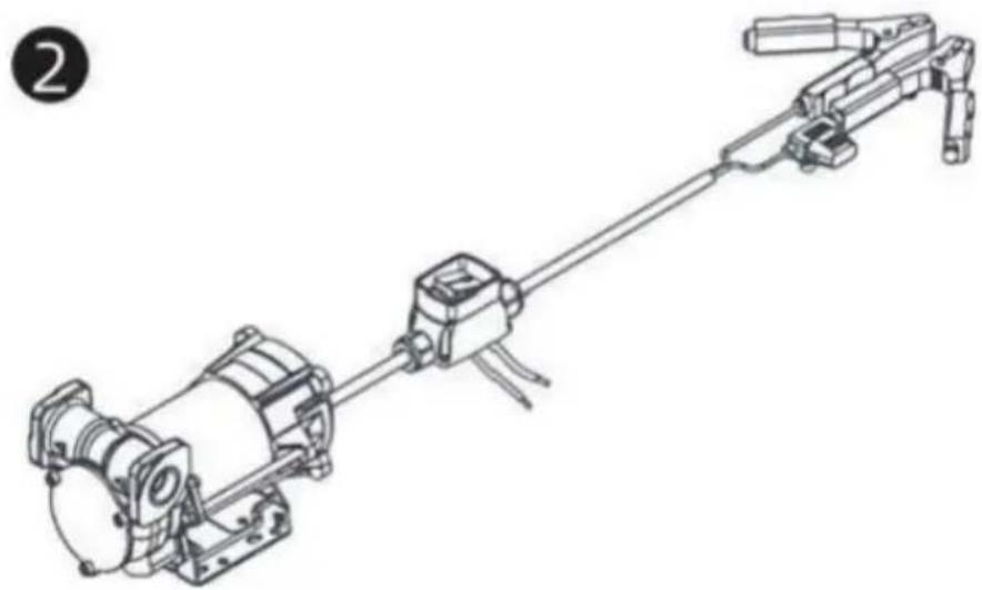
natural_image
Technical line drawing of a mechanical assembly with no visible text or symbols
natural_image
Technical line drawing of a mechanical assembly with no visible text or symbols
t is preferable to place Case Switch with pliers sheltered from atmospheric agents.
ts installation must be carried out by specialized personnel and carried out according to the instructions provided in this document


natural_image
Technical line drawing of a mechanical assembly with no visible text or symbols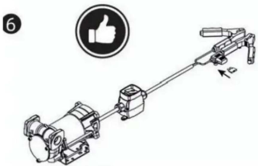
natural_image
Technical line drawing of a mechanical assembly with a thumbs-up icon (no text or symbols on the diagram itself)
DANGER!
Fumes accumulated whilefueling create an Explosive Atmosphere. It is CRITICAL that all possible sources of ignition be removed to a safe distance or extinguished. Sources of ignition would include (but not be limited to) open flames, cigarettes, static discharge, or electrical connection that can create a spark. Explosion, fire, and severe injury or death will occur if the explosive vapors are ignited.
Fumes accumulated whilefueling create an explosive Atmosphere around the tank that is beingfiled Toavoidpossible explosion of accumulated vapors, it is critical to keep possible sources of spark/ignition at safe distances from the fuelvapors
The accompanying diagram shows minimum safe distances for safe fueling 3m is the minimum safe distance between.
-Power source, switch and fuel supply.
-Power source, switch and thank being filled.
-Power source, switch and pump.

flowchart
graph TD
    A["PUMP INLET SIDE TANK"] --> B["POWER CORD"]
    B --> C["SWITCH"]
    C --> D["FUSE 25A"]
    E["SIDE TANK"] --> F["2.5M MIN."]
    F --> G["3M MIN."]
    H["Ground"] --> I["+ -"]
WARNING
●STATIC EL ECTRIC SPARK EXPLOSION HAZARD
● NEVER fill portable containers that are in oron vehicl

natural_image
Symbolic icon depicting a person using a tool to lift a vehicle, enclosed in a circle with radiating lines (no text or symbols)● ALWAYS PLACE CONTAINERS ON GROUND
- Keep nozzle in contact with container while flli

Astatic electric sparkcanoccur when fling portable containers sitting ontruck bed liners, or on any vehicle' scarpeting orfloor mating. This spark will explosively ignite gasoline vapor hire and cause SERIOUSINJURY or DEATH
FCC Information:
YH CONSULTING LIMITED. C/O YH Consulting Limited Office 147, Centurion House, London Road, Staines-upon-Thames, Surrey, TW18 4AX
| EC | REP |
www.vevor.com/support
VEVOR
Affordable. Reliable. Home Improvement.
PORTATILE SERBATOIO DIESEL E BENZINA
MODELLO: YDIES200L-E / YDIES400L-E
www.vevor.com/support
VEVOR
Affordable. Reliable. Home Improvement.
PORTABLE DIESEL GASOLINE TAN
MODELLO: YDIES200L-E / YDIES400L-E
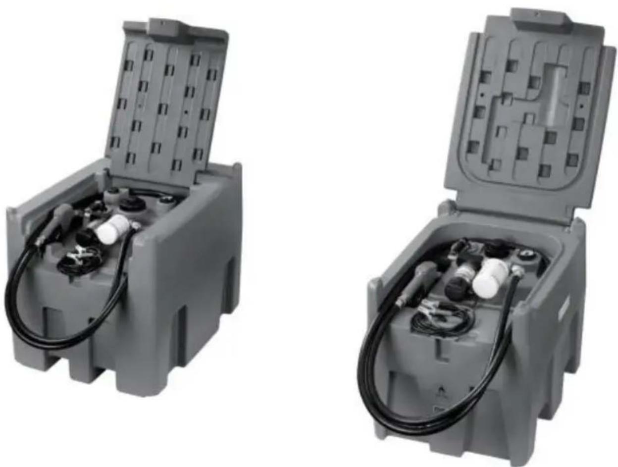
natural_image
Two identical gray industrial electrical enclosures with visible wiring and components, no text or symbols present.Foto di riferimento
Operation and Installation
PREPARAZIONE IL TRASFERIRE UNITÀ PER OPERAZIONE:
| FORBIDDEN USE | Using the appliance for fluids other than those listed at paragraph “Fluids permitted” and for uses other than those described at the item “authorised use” is forbidden. |
| PLANT OPERATION RESTRICTIONS IT IS FORBIDDEN: | |
| 1 | To use the appliance in a construction configuration other than that contemplated by the manufacturer |
| 2 | To use the appliance with fixed guards tampered with or removed. |
| 3 | To use the appliance in places where there is risk of explosion and/or fires classified in the following zones: 0; 20; 21; 22 |
| 4 | To integrate other systems and/or equipment not considered by the manufacturer in the executive project. |
| 5 | To connect the appliance up to energy sources other than those contemplated by the manufacturer |
| 6 | To use the commercial devices for purposes other than those indicated by the manufacturer. |
| 7 | To use in case of lightnings |
WARNING
INSTALL AWAY FROM STRONG ELECTROMAGNETIC FIELDS
HANDLING AND TRANSPORT
Due to the limited weight and dimensions of the pumps, special lifting equipment is not required to handle them. The pumps are carefully packed before dispatch. Check the packing when receiving the material and store in a dry place.
GENERAL WARNINGS
| Important precautions | To ensure operator safety and to protect the pump from potential damage, workers must be fully acquainted with this instruction manual before performing any operation. |
| Symbols used in the manual | The following symbols will be used throughout the manual to highlight safety information and precautions of particular importance: |

WARNING
WARNING indicates a hazardous situation which, if not avoided, could result in death or serious injury

NOTICE
NOTICE is used to address pratices not related to personal injury
Manual preservation
This manual should be complete and legible throughout. It should remain available to end users and specialist installation and maintenance technicians for consultation at any time.
| NOTICE | | ALWAYS USETHE RIGHT VOLTAGES TO CONNECTTHE PUMPS |
| WARNING | | BEFORE PROCEEDING WITH THE REFUELLING OF AIRCRAFTS, ENSURE THAT THE SYSTEM INTENDED FOR SUCH ACTION COMPLIES WITH THE REGULATIONS IN FORCE IN THE COUNTRYOF USE |
| WARNING | | USE THE PUMP ONLYWITH EFLUIDS PERMITTEDDO NOT USE WITHFLUIDS NOT PERMITTED TOAVOID DAMAGING THE PUMP THE WARRANTYLAPSES IN CASE OF MISUSE OF THE FLUID. |
| DO NOT USE THE PUMP WITH LIQUID FOOD PRODUCTS AND/OR WATER-BASED FLUIDS. | ||
| DO NOT OPERATE THE PUMPDRYTO AVOID DAMAGE. | ||
| Before connection, make sure that the piping and the suction tank are free of dirt and solid residue that could damage the pump and its accessories. NEVER COLLECT THE FLUID FROM THE BOTTOM OF THE TANK SINCE IT MAY CONTAIN IMPURITIES | ||
| Keep a working fire extinguisher in the work area. | ||
| Do not operate the unit when fatigued or under the influence of drugs or alcohol. | ||
| Do not alter or modify equipment. Alterations or modifications may void agency approvals and create safety hazards | ||
| Keep children and animals away from work area. | ||
| Comply with all applicable safety regulations.Do not use in case of lightnings |

BEFORE USING THE PUMP SWITCH OFF ALL THE ELECTRONIC DEVICES(I.E. MOBILE PHONES,BEEPERS ETC.)
FIRST AID RULES
Contact with the product
Persons who have suffered electric shock
In the event of problems developing following EYE/SKIN CONTACT, INHALATION or INGESTION of the treated product, please refer to the SAFETY DATA SHEET of the fluid handled.
Disconnect the power source, or use adry insulator to protect yourself while you move the injured person away from any electrical conductor. Avoid touching the injured person with your bare hands until he is far away from any conductor. Immediately call or help from qualified and trained personnel. Do not operate switches with wet hands.
NOTICE

SMOKING PROHIBITED
Please refer to the safety data sheet for the product

GENERAL SAFETY RULES
USER'S RESPONSIBILITY

IT IS ESSENTIAL TO GET TO KNOW AND UNDERSTAND THE INFORMATION CONTAINED IN THIS MANUAL.
IT IS ESSENTIAL TO GET TO KNOW AND OBSERVE THE SAFETY SPECIFICATIONS FOR FLAMMABLE LIQUIDS.
BEFORE USING THE PUMP IT'S IMPORTANT TO TRAIN OPERATORS, INSTALLERS AND MAINTENANCE STAFF TO LETTHEM WORKINAPARTICULARAREA NO. 1AS MENTIONED BY DIRECTIVE 99/92/EC
| Essential protective equipment characteristics | In case of contact with theproduct and for good standard of behaviour,wear protective equipmentwhich is: .Suited to the operations that need to be performed .Resistant to products used To do so,please refer to the relevant technical datasheets of the fuid used. | ||
| Personal protective equipment that must be worn | | | |
| safety shoes | close-fiting | dofthing | |
| | ||
| Necessary safety devices | protection gloves | safety goggles | |
| instructions manual | ||
| Protective gloves | Prolonged contact with the treated product may cause skin irritation;always wear protective gloves during dispensing. | ||
| WARNING | ENFORCE REGULATIONS FOR ELECTRICAL INSTALLATIONALL WIRING AND ELECTRICAL CONNECTIONS MUST BE PERFORMED BY AUTHORIZED AND SUITABLY TRAINED PERSONNEL.Never touch the electric plug or socket with wet hands.Do not switch the dispensing system on if the network connection cable or important parts of the apparatus are damaged,such as the inlet/outlet pipe, nozzle or safety devices.Replace the damaged pipe immediately. | ||
| WARNING | The electrical connection between the plug and socket must be kept well away from waterTHE PUMP IS EQUIPPED WITH CURRENT-SENSING PROTECTION. IF IT ACTIVATES TURN OFF THE PUMP IMMEDIATELY.THE PUMP IS EQUIPPED WITH PROTECTION AGAINST OVERHEATING AND OVERLOAD RISKS. SHOULD SUCH DEVICES ACTIVATE, THE PUMP SHUTS DOWN AUTOMATICALLY, BUT THE MASTER SWITCH IS NOTTURNED OFF.IT IS IMPORTANT TO STOP THE PUMP USING ITS SWITCH. THE PUMP RESTARTS AFTER ITS NORMAL OPERATING CONDITIONS HAVE BEEN RESTORED. | ||
| WARNING | FAILURE TO OBSERVE THE ABOVE MENTIONED RULES CAN CAUSE SERIOUS ACCIDENTSSHOULD THE HEAT SENSOR ACTIVATE UNDER NORMAL USE CONDITIONS, PLEASE CONTACT THE TECHNICALSUPPORT | ||
| NOTICE | TO PREVENT ELECTRIC SHOCK AND DETONATION OF SPARKS, ALL PUMPING SYSTEM MUST HAVE PROPER GROUNDING, INCLUDING TANK AND ANY ACCESSORIES | ||
TECHNICAL DATA PERFORMANCE SPECIFICATIONS
The performance diagram shows flow rate as a function of back pressure.
| Absorption (A) | FlowRate (/min)-(gpm) | Back Pressure (bar)-(psi) | ||
| Functioning Point | ||||
| A = (Maximum Flow Rate) | 15 | 35-9 | 0,2 -3 | |
| C • (By-Pass) | 25 | 0 | 1] 6 | |
| ATTENTION | The curve refers to the following operating conditions:Fluid: PETROL,Temperature: 20°C Suction conditions: The pipe and the pump position relative to the fluid level is such that a low pressure of O.3 bar is generated at the nominal flow rate.Under different suction conditions higher low pressure values can be created that reduce the flow rate compared to the same back pressure values. To obtain the best performance, it is very important to reduce loss of suction pressure as much as possible by following these instructions:· shorten the suction pipe as much as possible· avoid useless elbows or throttling in the pipes· keep the suction filter clean· use a pipe with a diameter equal to, or greater than, indicated (see Installation). | |||
OPERATING CONDITIONS
ENVIRONMENTAL CONDITIONS
| AMBIENTTEMPERATUREFLUIDTEMPERATURERELATIVEHUMIDITY | min.+23°F/max+104°Fmin.-10°C/max+40C | |
| min.+23°F/max+104°Fmin.-10C7max+40C | ||
| max.90% | ||
| WARNING | | The temperature limits shown apply to the pump components and must be respected to avoid possible damage or malfunction. |
ELECTRICAL POWER SUPPLY
| NOTICE | | The pump must be powered by DC line, the nominal values of which are indicated on the table in the paragraph"ELECTRICAL DATA"The maximum acceptable variations from the electrical parametersare:Voltage:+/-5%of the EX30 nominal value+/-10%of the EX20 nominal valueFrequency:+/-2%of the nominal value |
| WARNING | | Power supply from lines with values that do not fall within the indicated limits could cause damage to the electrical and electronic components. |
DUTY CYCLE
| NOTICE | | In conditions of maximum T.Environment( 40^ c)and at the nominal transfer conditions:-The EX30 pumps have been designed for intermittent use and a 30 min duty cycle.ONand 60 min OFF-The EX20 pumps have been designed for operating conditions S1 |
| WARNING | | Functioning under by-passconditions is only allowed for short periods of time (max. 30 seconds). |
FLUIDS PERMITTED
| WARNING | | THE PUMP CAN BE USED -DIESEL -KEROSENE -PETROL -AVGAS -PETROLALCOHOL 100/100LL (pump) | ONLYWITH THE FOLLOWING FLUIDS: | |||
| MIXED MAX15% only)-JETA/A1 (pump only) | ||||||
| -ASPEN2/4 | ||||||
INSTALLATION
| WARNING | | BEFOREANYOPERATION, ENSURE TO BE OUT OFPOTENTIALLYEXPLOSIVE AREAS |
| The pump must never be operated before the delivery and suction lines have been connected |
PRELIMINARY -Verify that all components are present. Request any missing parts from the manufacturer INSPECTION -Check that the pump has not suffered any damageduringtransport or storage.
-Carefullyclean the suction and delivery inlets and outlets, removing any dust or other packaging material that may be present.
Check that the electrical data corresponds to those indicated on the data plate
-Always install in anilluminated area.
Install the pump at a height of min. 80 cm
| WARNING | | IF VALVES IN THE CIRCUIT ARE TO BE INSTALLED,MAKE SURE THEY ARE EQUIPPED WITH OVERPRESSURE SYSTEM. | ||||||||
| CLEAN | THE | TANK | AND | MAKE | SURE | IT | IS | WELL- | ||
| VENTILATED (RECOMMENDED) | OPENING | PRESSURE:3psi | ||||||||
| WARNING | | DO NOT BLOCK THE DRAINAGE HOLES | ||||||||
POSITIONING, CONFIGURATIONS AND ACCESSORIES
| NOTICE | | The pump must be secured in a stable manner. |
| WARNING | | It is the installer's responsibility to provide the line accessories necessary for the safe and proper functioning of the pump. The accessories that are not suitable to be used with the previously indicated material could damage the pump and/or cause injury to persons, as well as causing pollution. |
| To maximise performance and prevent damage that could affect pump operation, always demand original accessories. | ||
NOTES ONSUCTIONAND DELIVERY LINES
DELIVERY
The selection of the pump model must be made taking into account the characteristics of the system
The combination OF:thelength of the pipe,the diameter of thepipe,as well as the accessories installed, could create back pressure that are greater than the maximum predicted pressure,thereby causing the pump's electronic controls to intervene and reducing the dispensed flow considerably.
In these cases, to guarantee correct operation of the pump, it is necessary to reduce the resistance of the system using pipes that are shorter or that have a greater diameter, as well as line accessories with smaller resistances (e.g. an automatic dispensing nozzle with greater flow rate capacity)
SUCTION
Self-priming pumps are characterized by excellent suction capacity.
During the start-up phase, when the suction pipe is empty and the pump is wet with the fluid, the electric pump unit is able to suck liquid from a maximum vertical distance of 2m
It is important to note that it could take up to 1 minute for the pump to prime and that the presence of an automatic dispensing nozzle on the delivery side will prevent the air trapped during the installation from being released and, therefore, the correct priming of the pump. For this reason, it is always advisable to prime the pump without an automatic delivery nozzle, verifying the proper wetting of the pump
Always install a foot valve to prevent the suction pipe from being emptied and to keep the pump wet at all times In this way, the pump will always start up immediately the next times it is used. When the system is in operation, the pump can operate with back pressures of up to 05 bars on the suction inlet; beyond this point, the pump may begin to cavitate resulting in a drop of the flow rate and an increase in the noise levels of the system.
In light of this, it is important to guarantee small back pressures on the suction side, by using short pipes with diameters that are equal to or larger than those recommended, reducing bends to a minimum, and using filters with a large cross-section and foot valves with minimum possible resistance on the suction side. It is very important to keep the suction filters clean because, when they become clogged, they increase the resistance of the system
The vertical distance between the pump and the fluid must be kept as short as possible, and it must fall within the 2m maximum required for priming. If the distance is greater, a foot valve must be installed to allow the suction pipes to fill up and the diameter pipes must be larger. It is however recommended that pump not be installed if the vertical distance is greater than 3m.
| WARNING | If the suction tank is higher than the pump, an anti-siphon valve should be installed to prevent accidental diesel fuel leaks. Dimension the installation in order to controlthebackpressures due towater hammering |
| It is a good system practice to install vacuum and air pressure gauges right at the inlets and outlets of the pump, which allow verification that operating conditions are within anticipated limits. To prevent the suction pipes frombeing emptied when the pump stops, a foot valve should be installed. | |
| THE INSTALLER IS RECOMMENDED TO INSTALLASUCTION FILTER. | |
CONNECTIONS
ELECTRICAL CONNECTIONS
| WARNING | | BEFORE ANYOPERATION, ENSURE TO BE OUT OF POTENTIALLYEXPLOSIVE AREAS |
| IT IS THE INSTALLER'S RESPONSIBILITY TO CARRY OUT THE ELECTRICAL CONNECTIONS IN COMPLIANCE WITH THE RELEVANT STANDARDS. | ||
| NOTICE | | BLACK CABLE: “■” (negative pole)RED CABLE: “+” (positive pole) |
| WARNING | | DO NOT CUT THE CABLE FOR ANY REASON |
| WARNING | | Comply with the following (not exhaustive)instructions to ensure a proper electrical connection: |
During installation and maintenance make sure that power supply to the electric lines has been turned off. -Use cables with minimum sections, rated voltages and installation type that are suitable for the characteristics indicated in paragraph "ELECTRICAL DATA" and the installation environment. -Always make sure that the cover of the terminal strip box is closed before switching on the power supply, after having checked the integrity of the seal gaskets that ensure the IP55 protection grade. For those screws use a 10 nm clamping couple
| WARNING | | All motors are equipped with a grounding terminal.Make sure all the plantis properly grounded. |
| NOTICE | | IN THE EVENT OF INSTALLATION IN ZONES WHICH ARE NOT CLASSIFIED, ITIS SUFFICIENT TO OBSERVE THE MINIMUM SAFETY STANDARDS ALREADYMENTIONED IN THIS MANUAL. |
| WARNING | | -THE OWNER HAS THE RESPONSIBILITY TO VERIFY THAT ALL THE LOCALAND NATIONAL REGULATIONS HAVEBEEN OBSERVED.-MAKE SURE THAT THE CABLE CONNECTING THE BATTERY IS PROTECTEDFROM HEAT SOURCES AND SHARP EDGES. INSTALL THE FUSE CLOsertoTHE BATTERY. |
| WARNING | | FAILURE TO OBSERVE THE ABOVE MENTIONED RULES CAN CAUSE SERIOUSACCIDENTS |
| WARNING | | IN CASE THE ELECTRICAL CABLING IS IN CLASSIFIED AREA, A CABLINGWITH PROTECTION DEGREESUITABLE TO THE WORKING AREA SHOULD BEPERFORMED. |
| WARNING | | PREVENT THE INSTALLATION OF ASTOP BUTTON INA REACHABLE POSITIONANDWITHADEGREEOFPROTECTIONSUITABLEFOR THE CLASSIFICATIONOFTHE PUMP ONWHICH ITIS INSTALLED. |
PIPING CONNECTIONS
| FOREWORD | -Before carrying out any connection, refer to the visual indications ie arrow on the pump head, to identify suction and delivery |
| WARNING | Wrong connection can cause serious pump damage. |
| PRELIMINARY INSPECTION | Before connection, make sure that the piping and the suction tank are free of dirt and solid residue that could damage the pump and its accessories. NEVER COLLECT THE FLUID FROM THE BOTTOM OF THE TANK SINCEIT MAY CONTAIN IMPURITIES- Before connecting the delivery pipe, partially fill the pump body, from delivery side, with the liquid that needs to be pumped in order to facilitate priming.- Do not use conical threaded fittings, which could damage the threaded inlet or outlet openings of the pump if excessively tightened. |
INITIAL START-UP
| FOREWORD | Check that the quantity of fluid in the suction tank is greater than the amount you wish to transfer.-Makesure that the residual capacity of the delivery tank is greater than the quantity you wish to transfer.-Make sure that the piping and line accessories are in good condition. |
| NOTICE | THIS PUMP IS NOT PROVIDED FOR FURTHER REGULATION OF DELIVERY AND PRESSURE |
| WARNING | Fluid leaks can damage objects and injure persons. |
| NOTICE | -Never start or stop the pump by connecting or cutting out the power supply.-Prolonged contact with some fluidscan damage the skin.The use of goggles and glovesis recommended. |
| IF THE PUMP DOES NOT PRIME | Depending on the system characteristics,the priming phase can last from several seconds to a few minutes.If thisphase is prolonged,stop thepump and verify:-that the pump is not running completelydry (fill with fluid from thedelivery line);-that the suction pipe guarantees against air infiltration;that the suction filter is not clogged;that the suction height is not higher than 2 mt.that all air has been released from the delivery pipe. |
| AT THE END OF THE INITIAL START-UP | When priming has occurred,verify that the pumpis operating within the anticipated range,in particular:-that under conditions of maximum back pressure,the powerabsorption of the motor stays within the values shown on the identification plate;that the delivery back pressure does not exceed the maximum back pressure for the pump |
EVERYDAY USE
USE PROCEDURE
1 Inflexible pipes are used, attach the ends of the piping to the tanks. In the absence of an appropriate slot, solidly grasp the delivery pipe before beginning dispensing.
2 Before starting the pump make sure that the delivery valve is closed (dispensing nozzle or line valve) or make sure that the delivery pipe is properly inserted inside the destination tank.
3 Turn the ON/OFF switch on
4 Open the delivery valve, solidly grasping the pipe
5 While dispensing.do not inhale the pumped product
6 If any treated fluid leaks out during dispensing, take all steps necessary to ensure the leaked fluid is cleaned up and safe as specified on the product technical sheet.
7 Close the delivery valve to stop dispensing and switch off the pump, or switch off the pump and then close the delivery valve
| WARNING | | THE WORKING OPERATIONS MUST ALWAYS BE GUARDED BY THI OPERATOR. |
| The by-pass valve allows functioning with delivery closed only for short periods (max. 3 minutes) | ||
| To avoid damaging the pump, after use, make sure the pump is off. | ||
| In case of a power break, switch the pump off straight away. | ||
| Should any sealants be used on the suction and delivery circuit of the pump make sure that these products are not released inside the pump. | ||
| Foreign bodies in the suction and delivery circuit of the pump could cause malfunctioning and breakage of the pump components. |
M△INTEN△NCE
Safety instructions The pump is designed and constructed to require a minimum of maintenance. Before carrying out any maintenancework,disconnect the pump from any electrical and hydraulic power source. During maintenance,the use of personal protective equipment (PPE)is compulsory. In any case always bear in mind the following basic recommendationsfor a goodfunctioning of the pump
| WARNING | | BEFORE ANYOPERATION, ENSURE TO BE OUTOF AREAS FOR SAFETY REASONS IT'S NOTALLOWEDTO PARTS: (1) BOTTOM (2) MOTOR PIPE(3) PUMP BODY | POTENTIALLYEXPLOSIVE DISASSEMBLE THESE | ||||||
| FOR SAFETY REASONS IT IS FORBIDDEN TO REMOVE PLATE" (1), "MOTOR TUBE" (2) AND "FRONT SHIELD" (3). | THE PARTS | "BOTTOM | |||||||
| Authorised maintenance personnel | All maintenance must be performed by qualified personnel.Tampering can lead to performance degradation,danger topersons and/or propertyand may resultin the warranty and UL/ATEXCERTIFICATION being voided. |
| Measures to be taken | Check that the labels and plates found on the dispensing system do not deteriorate or become detachedover time. |
| ONCEAWEEK: | -Check that the pipe connections are not loose to prevent any leaks;-Check and keep the filter installed on the suction line clean. |
| ONCE A MONTH: | -Check the pump body and keep it clean and free of any impurities;-Check that the electrical supply cables are in good condition. |
NOISE LEVEL
Under normal operating conditions, noise emission of all models does not exceed 74dB at a distance of 1 metre from the electric pump.
PROBLEMS AND SOLUTIONS
For any problems contact the authorised dealer nearest to you.
| PROBLEM | POSSIBLE CAUSE | CORRECTIVE ACTION |
| THEMOTOR IS NOT TURNING | Lackof electric power | Check the electrical connections and the satety systems |
| Rotor jammed | Check for possible damage or obstruction of the rotating components. | |
| Motor problems | Contact the Service Department | |
| THE MOTOR TURNS SLOWLY WHEN STARTING | Low voltage in the electric power line | Bring the voltage back within the anticipated limits |
| LOWOR NO FLOWRATE | Low level in the suction tank | Refill the tank |
| Foot valve blocked | Clean and/or replace the valve | |
| Filter clogged | Clean the filter | |
| Excessive suction pressure | Lower the pump with respect to the level of the tank or increase the cross-section of the piping | |
| High loss of head in the delivery circuit (working with the by-pass open) | Use shorter piping or of greater diameter | |
| By-pass valve blocked | Dismantle the valve, clean and/or replace it | |
| Air entering the pump or the suction piping | Check the seals of the connections | |
| A narrowing in the suction piping | Use piping suitable for working under suction pressure | |
| Low rotation speed | Check the voltage at the pump. Adjust the voltage and/or use cables of greater cross-section | |
| The suction piping is resting on the bottom of the tank | Raise the piping | |
| INCREASED PUMP NOISE | Cavitation occurring | Reduce suction pressure |
| Irregularfunctioning of the by-pass | Dispense until the air is purged from the bypass system | |
| Presence of air in the fluid | Verify the suction connections | |
| LEAKAGE FROM THE PUMP BODY | Seal damaged | Check and replace the seal |
| THE PUMP DOES NOT PRIME THE LIQUID | Suction circuit blocked | Remove the blockage from the suction circuit |
| Malfunction of foot valve fitted on suction circuit | Replace foot valve | |
| The suction chambers are dry | Add liquid from pump delivery side | |
| The pump chambers are dirty or blocked | Remove the blockages from the suction and delivery valves | |
| THE HEAT SENSOR ACTIVATES UNDER NORMAL OPERATING CONDITIONS | Operating fault | Contact the technical support |
DEMOLITION AND DISPOSAL
Foreword
Disposing of packing materials Metal Parts Disposal Disposal of electric and electronic components

Information regarding the environment for clients residing within the European Union
Miscellaneous parts disposal
If the system needs to be disposed, the parts which make it up must be delivered to companies that specialize in the recycling and disposal of industrial waste and, in particular: The packaging consists of biodegradable cardboard which can be delivered to companies for normal recycling of cellulose.
Metal parts, whether paint-finished or in stainless steel, can be consigned to scrap metal collectors. These must be disposed of by companies that specialize in the disposal of electronic components, in accordance with the indications of directive 2012/19/UE (see text of directive below).
European Directive 2012/19/UE requires that all equipment marked with this symbol on the product and/or packaging not be disposed of together with non-differentiated urban waste. The symbol indicates that this product must not be disposed of together with normal household waste. It is the responsibility of the owner to dispose of these products as well as other electric or electronic equipment by means of the specific refuse collection structures indicated by the government or the local governing authorities.
Disposing of RAEE equipment as household wastes is strictly forbidden. Such wastes must be disposed of separately.
Any hazardous substances in the electrical and electronic appliances and/or the misuse of such appliances can have potentially serious consequences for the environment and human health.
In case of the unlawful disposal of said wastes, fines will be applicable as defined by the laws in force.
Other components, such as pipes, rubber gaskets, plastic parts and wires, must be disposed of by companies specialising in the disposal of industrial waste.
INTERRUTTORE CASSA CON PINZA PER LA POMPA DEL SERBATOIO DE CARBURANTE

THESWTCH HAS NOT BEEN DESIGNED IN COMPLIANCE WITH ATEX REGULATION OR TO OPERATE IN ENVIRONMENTS WITH POTENTIALLY EXPLOSIVE ATMOSPHERE.
DO NOT INSTALL IN POTENTIALLY EXPLOSIVE LOCATIONS.

natural_image
Diagram of a mechanical assembly with an arrow indicating motion, showing a motor, gear, and shaft (no text or labels)
natural_image
Technical line drawing of a mechanical assembly with no visible text or symbols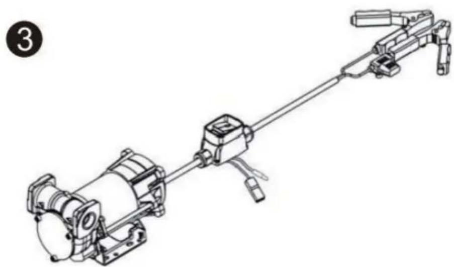
natural_image
Technical line drawing of a mechanical device with no visible text or symbols
t is preferable to place Case Switch with pliers sheltered from atmospheric agents.
ts installation must be carried out by specialized personnel and carried out according to the instructions provided in this document

natural_image
Technical line drawing of a mechanical assembly with no visible text or symbols
natural_image
Technical line drawing of a mechanical assembly with a thumbs-up icon (no text or symbols)
DANGER!
Fumes accumulated whilefueling create an Explosive Atmosphere. It is CRITICAL that all possible sources of ignition be removed to a safe distance or extinguished. Sources of ignition would include (but not be limited to) open flames, cigarettes, static discharge, or electrical connection that can create a spark. Explosion, fire, and severe injury or death will occur if the explosive vapors are ignited.
Fumes accumulated whilefueling create an explosive Atmosphere around the tank that is beingfiled Toavoidpossible explosion of accumulated vapors, it is critical to keep possible sources of spark/ignition at safe distances from the fuelvapors
The accompanying diagram shows minimum safe distances for safe fueling 3m is the minimum safe distance between.
-Power source, switch and fuel supply.
-Power source, switch and thank being filled.
-Power source, switch and pump.

flowchart
graph TD
    A["PUMP INLET SIDE TANK"] --> B["POWER CORD"]
    B --> C["SWITCH"]
    C --> D["FUSE 25A"]
    E["SIDE TANK"] --> F["2.5M MIN."]
    F --> G["3M MIN."]
    G --> H["Ground"]
WARNING
●STATIC EL ECTRIC SPARK EXPLOSION HAZARD
● NEVER fill portable containers that are in oron vehicl

natural_image
Symbolic icon depicting a person using a tool to lift a vehicle, enclosed in a circle with radiating lines (no text or symbols)● ALWAYS PLACE CONTAINERS ON GROUND
- Keep nozzle in contact with container while flli

Astatic electric sparkcanoccur when fling portable containers sitting ontruck bed liners, or on any vehicle' scarpeting orfloor mating- This spark will explosively ignite gasoline vapor hire and cause SERIOUSINJURY or DEATH
YH CONSULTING LIMITED. C/O YH Consulting
Limited Office 147, Centurion House, London Road, Staines-upon-Thames, Surrey, TW18 4AX
| EC | REP |
Affordable. Reliable. Home Improvement.
PORTÁTIL TANQUE DE DIÉSEL Y GASOLINA
MODELO: YDIES200L-E / YDIES400L-E
www.vevor.com/support
VEVOR
Affordable. Reliable. Home Improvement.
PORTABLE DIESEI GASOLINE TAN
MODELO: YDIES200L-E / YDIES400L-E

natural_image
Two identical gray industrial electrical enclosures with visible wiring and components, no text or symbols present.Foto de referencia
Operation and Installation
| FORBIDDEN USE | Using the appliance for fluids other than those listed at paragraph “Fluids permitted” and for uses other than those described at the item “authorised use” is forbidden. |
| PLANT OPERATION RESTRICTIONS IT IS FORBIDDEN: | |
| 1 | To use the appliance in a construction configuration other than that contemplated by the manufacturer |
| 2 | To use the appliance with fixed guards tampered with or removed. |
| 3 | To use the appliance in places where there is risk of explosion and/or fires classified in the following zones: 0; 20; 21; 22 |
| 4 | To integrate other systems and/or equipment not considered by the manufacturer in the executive project. |
| 5 | To connect the appliance up to energy sources other than those contemplated by the manufacturer |
| 6 | To use the commercial devices for purposes other than those indicated by the manufacturer. |
| 7 | To use in case of lightnings |
WARNING

INSTALL AWAY FROM STRONG ELECTROMAGNETIC FIELDS
HANDLING AND TRANSPORT
Due to the limited weight and dimensions of the pumps, special lifting equipment is not required to handle them. The pumps are carefully packed before dispatch. Check the packing when receiving the material and store in a dry place.
GENERAL WARNINGS
| Important precautions | To ensure operator safety and to protect the pump from potential damage, workers must be fully acquainted with this instruction manual before performing any operation. |
| Symbols used in the manual | The following symbols will be used throughout the manual to highlight safety information and precautions of particular importance: |

WARNING
WARNING indicates a hazardous situation which, if not avoided, could result in death or serious injury

NOTICE
NOTICE is used to address pratices not related to personal injury
Manual preservation
This manual should be complete and legible throughout. It should remain available to end users and specialist installation and maintenance technicians for consultation at any time.
| NOTICE | | ALWAYS USETHE RIGHT VOLTAGES TO CONNECTTHE PUMPS |
| WARNING | | BEFORE PROCEEDING WITH THE REFUELLING OF AIRCRAFTS, ENSURE THAT THE SYSTEM INTENDED FOR SUCH ACTION COMPLIES WITH THE REGULATIONS IN FORCE IN THE COUNTRYOF USE |
| WARNING | | USE THE PUMP ONLYWITH EFLUIDS PERMITTEDDO NOT USE WITHFLUIDS NOT PERMITTED TOAVOID DAMAGING THE PUMP THE WARRANTYLAPSES IN CASE OF MISUSE OF THE FLUID. |
| DO NOT USE THE PUMP WITH LIQUID FOOD PRODUCTS AND/OR WATER-BASED FLUIDS. | ||
| DO NOT OPERATE THE PUMPDRYTO AVOID DAMAGE. | ||
| Before connection, make sure that the piping and the suction tank are free of dirt and solid residue that could damage the pump and its accessories. NEVER COLLECT THE FLUID FROM THE BOTTOM OF THE TANK SINCE IT MAY CONTAIN IMPURITIES | ||
| Keep a working fire extinguisher in the work area. | ||
| Do not operate the unit when fatigued or under the influence of drugs or alcohol. | ||
| Do not alter or modify equipment. Alterations or modifications may void agency approvals and create safety hazards | ||
| Keep children and animals away from work area. | ||
| Comply with all applicable safety regulations.Do not use in case of lightnings |

BEFORE USING THE PUMP SWITCH OFF ALL THE ELECTRONIC DEVICES(I.E. MOBILE PHONES,BEEPERS ETC.)
FIRST AID RULES
Contact with the product
Persons who have suffered electric shock
In the event of problems developing following EYE/SKIN CONTACT, INHALATION or INGESTION of the treated product, please refer to the SAFETY DATA SHEET of the fluid handled.
Disconnect the power source, or use adry insulator to protect yourself while you move the injured person away from any electrical conductor. Avoid touching the injured person with your bare hands until he is far away from any conductor. Immediately call or help from qualified and trained personnel. Do not operate switches with wet hands.
NOTICE

SMOKING PROHIBITED
Please refer to the safety data sheet for the product

GENERAL SAFETY RULES
USER'S RESPONSIBILITY

IT IS ESSENTIAL TO GET TO KNOW AND UNDERSTAND THE INFORMATION CONTAINED IN THIS MANUAL.
IT IS ESSENTIAL TO GET TO KNOW AND OBSERVE THE SAFETY SPECIFICATIONS FOR FLAMMABLE LIQUIDS.
BEFORE USING THE PUMP IT'S IMPORTANT TO TRAIN OPERATORS, INSTALLERS AND MAINTENANCE STAFF TO LETTHEM WORKINAPARTICULARAREA NO. 1AS MENTIONED BY DIRECTIVE 99/92/EC
| Essential protective equipment characteristics | In case of contact with theproduct and for good standard of behaviour,wear protective equipmentwhich is: .Suited to the operations that need to be performed .Resistant to products used To do so,please refer to the relevant technical datasheets of the fuid used. | ||
| Personal protective equipment that must be worn | | | |
| safety shoes | close-fiting | dofthing | |
| | ||
| protection gloves | safety goggles | ||
| Necessary safety devices | | instructions manual | |
| Protective gloves | Prolonged contact with the treated product may cause skin irritation;always wear protective gloves during dispensing. | ||
| WARNING | ENFORCE REGULATIONS FOR ELECTRICAL INSTALLATIONALL WIRING AND ELECTRICAL CONNECTIONS MUST BE PERFORMED BY AUTHORIZED AND SUITABLY TRAINED PERSONNEL.Never touch the electric plug or socket with wet hands.Do not switch the dispensing system on if the network connection cable or important parts of the apparatus are damaged,such as the inlet/outlet pipe, nozzle or safety devices.Replace the damaged pipe immediately. | ||
| WARNING | The electrical connection between the plug and socket must be kept well away from waterTHE PUMP IS EQUIPPED WITH CURRENT-SENSING PROTECTION. IF IT ACTIVATES TURN OFF THE PUMP IMMEDIATELY.THE PUMP IS EQUIPPED WITH PROTECTION AGAINST OVERHEATING AND OVERLOAD RISKS. SHOULD SUCH DEVICES ACTIVATE, THE PUMP SHUTS DOWN AUTOMATICALLY, BUT THE MASTER SWITCH IS NOTTURNED OFF.IT IS IMPORTANT TO STOP THE PUMP USING ITS SWITCH. THE PUMP RESTARTS AFTER ITS NORMAL OPERATING CONDITIONS HAVE BEEN RESTORED. | ||
| WARNING | FAILURE TO OBSERVE THE ABOVE MENTIONED RULES CAN CAUSE SERIOUS ACCIDENTSSHOULD THE HEAT SENSOR ACTIVATE UNDER NORMAL USE CONDITIONS, PLEASE CONTACT THE TECHNICALSUPPORT | ||
| NOTICE | TO PREVENT ELECTRIC SHOCK AND DETONATION OF SPARKS, ALL PUMPING SYSTEM MUST HAVE PROPER GROUNDING, INCLUDING TANK AND ANY ACCESSORIES | ||
TECHNICAL DATA PERFORMANCE SPECIFICATIONS
The performance diagram shows flow rate as a function of back pressure.
| Absorption (A) | FlowRate (/min)-(gpm) | Back Pressure (bar)-(psi) | ||
| Functioning Point | ||||
| A = (Maximum Flow Rate) | 15 | 35-9 | 0,2 -3 | |
| C • (By-Pass) | 25 | 0 | 1] 6 | |
| ATTENTION | The curve refers to the following operating conditions:Fluid: PETROL,Temperature: 20°C Suction conditions: The pipe and the pump position relative to the fluid level is such that a low pressure of O.3 bar is generated at the nominal flow rate.Under different suction conditions higher low pressure values can be created that reduce the flow rate compared to the same back pressure values. To obtain the best performance, it is very important to reduce loss of suction pressure as much as possible by following these instructions:· shorten the suction pipe as much as possible· avoid useless elbows or throttling in the pipes· keep the suction filter clean· use a pipe with a diameter equal to, or greater than, indicated (see Installation). | |||
OPERATING CONDITIONS
ENVIRONMENTAL CONDITIONS
| AMBIENTTEMPERATUREFLUIDTEMPERATURERELATIVEHUMIDITY | min.+23°F/max+104°Fmin.-10°C/max+40Cmin.+23°F/max+104°Fmin.-10C7max+40Cmax.90% | |
| WARNING | | The temperature limits shown apply to the pump components and must be respected to avoid possible damage or malfunction. |
ELECTRICAL POWER SUPPLY
| NOTICE | | The pump must be powered by DC line, the nominal values of which are indicated on the table in the paragraph"ELECTRICAL DATA"The maximum acceptable variations from the electrical parametersare:Voltage:+/-5%of the EX30 nominal value+/-10%of the EX20 nominal valueFrequency:+/-2%of the nominal value |
| WARNING | | Power supply from lines with values that do not fall within the indicated limits could cause damage to the electrical and electronic components. |
DUTY CYCLE
| NOTICE | | In conditions of maximum T.Environment( 40^ c)and at the nominal transfer conditions:-The EX30 pumps have been designed for intermittent use and a 30 min duty cycle.ONand 60 min OFF-The EX20 pumps have been designed for operating conditions S1 |
| WARNING | | Functioning under by-passconditions is only allowed for short periods of time (max. 30 seconds). |
FLUIDS PERMITTED
| WARNING | | THE PUMP CAN BE USED -DIESEL -KEROSENE -PETROL -AVGAS -PETROLALCOHOL 100/100LL (pump) | ONLYWITH THE FOLLOWING FLUIDS: | |||
| MIXED MAX15% only)-JETA/A1 (pump only) | ||||||
| -ASPEN2/4 | ||||||
INSTALLATION
| WARNING | | BEFOREANYOPERATION, ENSURE TO BE OUT OFPOTENTIALLYEXPLOSIVE AREAS |
| The pump must never be operated before the delivery and suction lines have been connected |
PRELIMINARY -Verify that all components are present. Request any missing parts from the manufacturer INSPECTION -Check that the pump has not suffered any damageduringtransport or storage.
-Carefullyclean the suction and delivery inlets and outlets, removing any dust or other packaging material that may be present.
Check that the electrical data corresponds to those indicated on the data plate
-Always install in anilluminated area.
Install the pump at a height of min. 80 cm
| WARNING | | IF VALVES IN THE CIRCUIT ARE TO BE INSTALLED,MAKE SURE THEY ARE EQUIPPED WITH OVERPRESSURE SYSTEM. | ||||||||
| CLEAN | THE | TANK | AND | MAKE | SURE | IT | IS | WELL- | ||
| VENTILATED (RECOMMENDED) | OPENING | PRESSURE:3psi | ||||||||
| WARNING | | DO NOT BLOCK THE DRAINAGE HOLES | ||||||||
POSITIONING, CONFIGURATIONS AND ACCESSORIES
| NOTICE | | The pump must be secured in a stable manner. |
| WARNING | | It is the installer's responsibility to provide the line accessories necessary for the safe and proper functioning of the pump. The accessories that are not suitable to be used with the previously indicated material could damage the pump and/or cause injury to persons, as well as causing pollution. |
| To maximise performance and prevent damage that could affect pump operation, always demand original accessories. | ||
NOTES ONSUCTIONAND DELIVERY LINES
DELIVERY
The selection of the pump model must be made taking into account the characteristics of the system
The combination OF:thelength of the pipe,the diameter of thepipe,as well as the accessories installed, could create back pressure that are greater than the maximum predicted pressure,thereby causing the pump's electronic controls to intervene and reducing the dispensed flow considerably.
In these cases, to guarantee correct operation of the pump, it is necessary to reduce the resistance of the system using pipes that are shorter or that have a greater diameter, as well as line accessories with smaller resistances (e.g. an automatic dispensing nozzle with greater flow rate capacity)
SUCTION
Self-priming pumps are characterized by excellent suction capacity.
During the start-up phase, when the suction pipe is empty and the pump is wet with the fluid, the electric pump unit is able to suck liquid from a maximum vertical distance of 2m
It is important to note that it could take up to 1 minute for the pump to prime and that the presence of an automatic dispensing nozzle on the delivery side will prevent the air trapped during the installation from being released and, therefore, the correct priming of the pump. For this reason, it is always advisable to prime the pump without an automatic delivery nozzle, verifying the proper wetting of the pump
Always install a foot valve to prevent the suction pipe from being emptied and to keep the pump wet at all times In this way, the pump will always start up immediately the next times it is used. When the system is in operation, the pump can operate with back pressures of up to 05 bars on the suction inlet; beyond this point, the pump may begin to cavitate resulting in a drop of the flow rate and an increase in the noise levels of the system.
In light of this, it is important to guarantee small back pressures on the suction side, by using short pipes with diameters that are equal to or larger than those recommended, reducing bends to a minimum, and using filters with a large cross-section and foot valves with minimum possible resistance on the suction side. It is very important to keep the suction filters clean because, when they become clogged, they increase the resistance of the system
The vertical distance between the pump and the fluid must be kept as short as possible, and it must fall within the 2m maximum required for priming. If the distance is greater, a foot valve must be installed to allow the suction pipes to fill up and the diameter pipes must be larger. It is however recommended that pump not be installed if the vertical distance is greater than 3m.
| WARNING | If the suction tank is higher than the pump, an anti-siphon valve should be installed to prevent accidental diesel fuel leaks. Dimension the installation in order to controlthebackpressures due towater hammering |
| It is a good system practice to install vacuum and air pressure gauges right at the inlets and outlets of the pump, which allow verification that operating conditions are within anticipated limits. To prevent the suction pipes frombeing emptied when the pump stops, a foot valve should be installed. | |
| THE INSTALLER IS RECOMMENDED TO INSTALLASUCTION FILTER. | |
CONNECTIONS
ELECTRICAL CONNECTIONS
| WARNING | | BEFORE ANYOPERATION, ENSURE TO BE OUT OF POTENTIALLYEXPLOSIVE AREAS |
| IT IS THE INSTALLER'S RESPONSIBILITY TO CARRY OUT THE ELECTRICAL CONNECTIONS IN COMPLIANCE WITH THE RELEVANT STANDARDS. | ||
| NOTICE | | BLACK CABLE: “■” (negative pole)RED CABLE: “+” (positive pole) |
| WARNING | | DO NOT CUT THE CABLE FOR ANY REASON |
| WARNING | | Comply with the following (not exhaustive)instructions to ensure a proper electrical connection: |
During installation and maintenance make sure that power supply to the electric lines has been turned off. -Use cables with minimum sections, rated voltages and installation type that are suitable for the characteristics indicated in paragraph "ELECTRICAL DATA" and the installation environme nt. -Always make sure that the cover of the terminalstrip box is closed before switching on the power supply, after having checked the integrity of the seal gaskets that ensure the IP55 protection grade. For those screws use a 10 nm clamping couple
| WARNING | | All motors are equipped with a grounding terminal.Make sure all the plantis properly grounded. |
| NOTICE | | IN THE EVENT OF INSTALLATION IN ZONES WHICH ARE NOT CLASSIFIED, ITIS SUFFICIENT TO OBSERVE THE MINIMUM SAFETY STANDARDS ALREADYMENTIONED IN THIS MANUAL. |
| WARNING | | -THE OWNER HAS THE RESPONSIBILITY TO VERIFY THAT ALL THE LOCALAND NATIONAL REGULATIONS HAVEBEEN OBSERVED.-MAKE SURE THAT THE CABLE CONNECTING THE BATTERY IS PROTECTEDFROM HEAT SOURCES AND SHARP EDGES. INSTALL THE FUSE CLOsertoTHE BATTERY. |
| WARNING | | FAILURE TO OBSERVE THE ABOVE MENTIONED RULES CAN CAUSE SERIOUSACCIDENTS |
| WARNING | | IN CASE THE ELECTRICAL CABLING IS IN CLASSIFIED AREA, A CABLINGWITH PROTECTION DEGREESUITABLE TO THE WORKING AREA SHOULD BEPERFORMED. |
| WARNING | | PREVENT THE INSTALLATION OF ASTOP BUTTON INA REACHABLE POSITIONANDWITHADEGREEOFPROTECTIONSUITABLEFOR THE CLASSIFICATIONOFTHE PUMP ONWHICH ITIS INSTALLED. |
PIPING CONNECTIONS
| FOREWORD | -Before carrying out any connection, refer to the visual indications ie arrow on the pump head, to identify suction and delivery |
| WARNING | Wrong connection can cause serious pump damage. |
| PRELIMINARY INSPECTION | Before connection, make sure that the piping and the suction tank are free of dirt and solid residue that could damage the pump and its accessories. NEVER COLLECT THE FLUID FROM THE BOTTOM OF THE TANK SINCEIT MAY CONTAIN IMPURITIES- Before connecting the delivery pipe, partially fill the pump body, from delivery side, with the liquid that needs to be pumped in order to facilitate priming.- Do not use conical threaded fittings, which could damage the threaded inlet or outlet openings of the pump if excessively tightened. |
INITIAL START-UP
| FOREWORD | Check that the quantity of fluid in the suction tank is greater than the amount you wish to transfer.-Makesure that the residual capacity of the delivery tank is greater than the quantity you wish to transfer.-Make sure that the piping and line accessories are in good condition. |
| NOTICE | THIS PUMP IS NOT PROVIDED FOR FURTHER REGULATION OF DELIVERY AND PRESSURE |
| WARNING | Fluid leaks can damage objects and injure persons. |
| NOTICE | -Never start or stop the pump by connecting or cutting out the power supply.-Prolonged contact with some fluidscan damage the skin.The use of goggles and glovesis recommended. |
| IF THE PUMP DOES NOT PRIME | Depending on the system characteristics,the priming phase can last from several seconds to a few minutes.If thisphase is prolonged,stop thepump and verify:-that the pump is not running completelydry (fill with fluid from thedelivery line);-that the suction pipe guarantees against air infiltration;that the suction filter is not clogged;that the suction height is not higher than 2 mt.that all air has been released from the delivery pipe. |
| AT THE END OF THE INITIAL START-UP | When priming has occurred,verify that the pumpis operating within the anticipated range,in particular:-that under conditions of maximum back pressure,the powerabsorption of the motor stays within the values shown on the identification plate;that the delivery back pressure does not exceed the maximum back pressure for the pump |
EVERYDAY USE
USE PROCEDURE
1 Inflexible pipes are used, attach the ends of the piping to the tanks. In the absence of an appropriate slot, solidly grasp the delivery pipe before beginning dispensing.
2 Before starting the pump make sure that the delivery valve is closed (dispensing nozzle or line valve) or make sure that the delivery pipe is properly inserted inside the destination tank.
3 Turn the ON/OFF switch on
4 Open the delivery valve, solidly grasping the pipe
5 While dispensing.do not inhale the pumped product
6 If any treated fluid leaks out during dispensing, take all steps necessary to ensure the leaked fluid is cleaned up and safe as specified on the product technical sheet.
7 Close the delivery valve to stop dispensing and switch off the pump, or switch off the pump and then close the delivery valve
| WARNING | | THE WORKING OPERATIONS MUST ALWAYS BE GUARDED BY THI OPERATOR. |
| The by-pass valve allows functioning with delivery closed only for short periods (max. 3 minutes) | ||
| To avoid damaging the pump, after use, make sure the pump is off. | ||
| In case of a power break, switch the pump off straight away. | ||
| Should any sealants be used on the suction and delivery circuit of the pump make sure that these products are not released inside the pump. | ||
| Foreign bodies in the suction and delivery circuit of the pump could cause malfunctioning and breakage of the pump components. |
M△INTEN△NCE
Safety instructions The pump is designed and constructed to require a minimum of maintenance. Before carrying out any maintenancework,disconnect the pump from any electrical and hydraulic power source. During maintenance,the use of personal protective equipment (PPE)is compulsory. In any case always bear in mind the following basic recommendationsfor a goodfunctioning of the pump
| WARNING | | BEFORE ANYOPERATION, ENSURE TO BE OUTOF AREAS FOR SAFETY REASONS IT'S NOTALLOWEDTO PARTS: (1) BOTTOM (2) MOTOR PIPE(3) PUMP BODY | POTENTIALLYEXPLOSIVE DISASSEMBLE THESE | ||||||
| FOR SAFETY REASONS IT IS FORBIDDEN TO REMOVE PLATE" (1), "MOTOR TUBE" (2) AND "FRONT SHIELD" (3). | THE PARTS | "BOTTOM | |||||||
| Authorised maintenance personnel | All maintenance must be performed by qualified personnel.Tampering can lead to performance degradation,danger topersons and/or propertyand may resultin the warranty and UL/ATEXCERTIFICATION being voided. |
| Measures to be taken | Check that the labels and plates found on the dispensing system do not deteriorate or become detachedover time. |
| ONCEAWEEK: | -Check that the pipe connections are not loose to prevent any leaks;-Check and keep the filter installed on the suction line clean. |
| ONCE A MONTH: | -Check the pump body and keep it clean and free of any impurities;-Check that the electrical supply cables are in good condition. |
NOISE LEVEL
Under normal operating conditions, noise emission of all models does not exceed 74dB at a distance of 1 metre from the electric pump.
PROBLEMS AND SOLUTIONS
For any problems contact the authorised dealer nearest to you.
| PROBLEM | POSSIBLE CAUSE | CORRECTIVE ACTION |
| THEMOTOR IS NOT TURNING | Lackof electric power | Check the electrical connections and the satety systems |
| Rotor jammed | Check for possible damage or obstruction of the rotating components. | |
| Motor problems | Contact the Service Department | |
| THE MOTOR TURNS SLOWLY WHEN STARTING | Low voltage in the electric power line | Bring the voltage back within the anticipated limits |
| LOWOR NO FLOWRATE | Low level in the suction tank | Refill the tank |
| Foot valve blocked | Clean and/or replace the valve | |
| Filter clogged | Clean the filter | |
| Excessive suction pressure | Lower the pump with respect to the level of the tank or increase the cross-section of the piping | |
| High loss of head in the delivery circuit (working with the by-pass open) | Use shorter piping or of greater diameter | |
| By-pass valve blocked | Dismantle the valve, clean and/or replace it | |
| Air entering the pump or the suction piping | Check the seals of the connections | |
| A narrowing in the suction piping | Use piping suitable for working under suction pressure | |
| Low rotation speed | Check the voltage at the pump. Adjust the voltage and/or use cables of greater cross-section | |
| The suction piping is resting on the bottom of the tank | Raise the piping | |
| INCREASED PUMP NOISE | Cavitation occurring | Reduce suction pressure |
| Irregularfunctioning of the by-pass | Dispense until the air is purged from the bypass system | |
| Presence of air in the fluid | Verify the suction connections | |
| LEAKAGE FROM THE PUMP BODY | Seal damaged | Check and replace the seal |
| THE PUMP DOES NOT PRIME THE LIQUID | Suction circuit blocked | Remove the blockage from the suction circuit |
| Malfunction of foot valve fitted on suction circuit | Replace foot valve | |
| The suction chambers are dry | Add liquid from pump delivery side | |
| The pump chambers are dirty or blocked | Remove the blockages from the suction and delivery valves | |
| THE HEAT SENSOR ACTIVATES UNDER NORMAL OPERATING CONDITIONS | Operating fault | Contact the technical support |
DEMOLITION AND DISPOSAL
Foreword
Disposing of packing materials Metal Parts Disposal Disposal of electric and electronic components

Information regarding the environment for clients residing within the European Union
Miscellaneous parts disposal
If the system needs to be disposed, the parts which make it up must be delivered to companies that specialize in the recycling and disposal of industrial waste and, in particular: The packaging consists of biodegradable cardboard which can be delivered to companies for normal recycling of cellulose.
Metal parts, whether paint-finished or in stainless steel, can be consigned to scrap metal collectors. These must be disposed of by companies that specialize in the disposal of electronic components, in accordance with the indications of directive 2012/19/UE (see text of directive below).
European Directive 2012/19/UE requires that all equipment marked with this symbol on the product and/or packaging not be disposed of together with non-differentiated urban waste. The symbol indicates that this product must not be disposed of together with normal household waste. It is the responsibility of the owner to dispose of these products as well as other electric or electronic equipment by means of the specific refuse collection structures indicated by the government or the local governing authorities.
Disposing of RAEE equipment as household wastes is strictly forbidden. Such wastes must be disposed of separately.
Any hazardous substances in the electrical and electronic appliances and/or the misuse of such appliances can have potentially serious consequences for the environment and human health.
In case of the unlawful disposal of said wastes, fines will be applicable as defined by the laws in force.
Other components, such as pipes, rubber gaskets, plastic parts and wires, must be disposed of by companies specialising in the disposal of industrial waste.
INTERRUPTOR DE CAJA CON ALICATES PARA LA BOMBA DEL DEPÓSIT DE COMBUSTIBLE

THESWTCH HAS NOT BEEN DESIGNED IN COMPLIANCE WITH ATEX REGULATION OR TO OPERATE IN ENVIRONMENTS WITH POTENTIALLY EXPLOSIVE ATMOSPHERE.
DO NOT INSTALL IN POTENTIALLY EXPLOSIVE LOCATIONS.


natural_image
Technical line drawing of a mechanical assembly with no visible text or symbols
natural_image
Technical line drawing of a mechanical device with no visible text or symbols
t is preferable to place Case Switch with pliers sheltered from atmospheric agents.
ts installation must be carried out by specialized personnel and carried out according to the instructions provided in this document


natural_image
Technical line drawing of a mechanical assembly with no visible text or symbols
natural_image
Technical line drawing of a mechanical assembly with a thumbs-up icon (no text or symbols)
DANGER!
Fumes accumulated whilefueling create an Explosive Atmosphere. It is CRITICAL that all possible sources of ignition be removed to a safe distance or extinguished. Sources of ignition would include (but not be limited to) open flames, cigarettes, static discharge, or electrical connection that can create a spark. Explosion, fire, and severe injury or death will occur if the explosive vapors are ignited.
Fumes accumulated whilefueling create an explosive Atmosphere around the tank that is beingfiled Toavoidpossible explosion of accumulated vapors, it is critical to keep possible sources of spark/ignition at safe distances from the fuelvapors
The accompanying diagram shows minimum safe distances for safe fueling 3m is the minimum safe distance between.
-Power source, switch and fuel supply.
-Power source, switch and thank being filled.
-Power source, switch and pump.
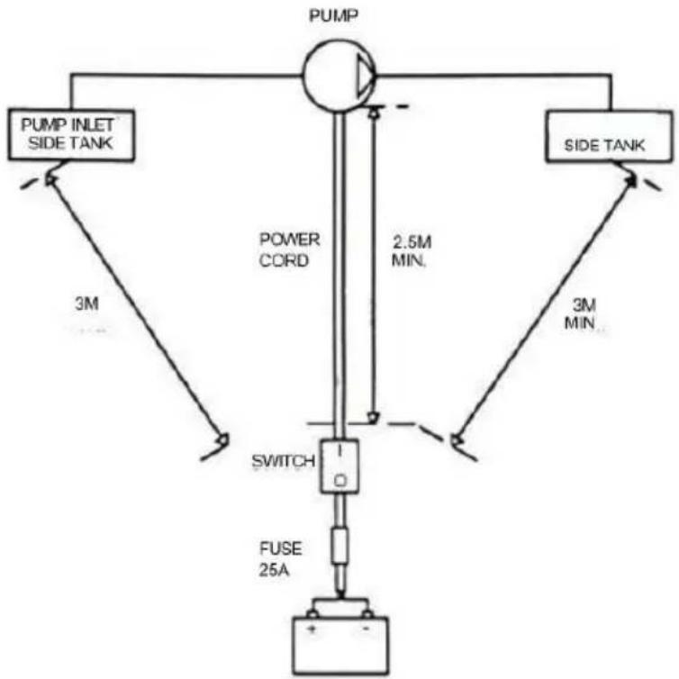
flowchart
graph TD
    A["PUMP INLET SIDE TANK"] --> B["POWER CORD"]
    B --> C["SWITCH"]
    C --> D["FUSE 25A"]
    E["SIDE TANK"] --> F["2.5M MIN."]
    F --> G["3M MIN."]
    H["Ground"] --> I["+ -"]
WARNING
●STATIC EL ECTRIC SPARK EXPLOSION HAZARD
● NEVER fill portable containers that are in oron vehicl

natural_image
Symbolic icon depicting a person using a tool to lift a vehicle, enclosed in a circle with radiating lines (no text or symbols)● ALWAYS PLACE CONTAINERS ON GROUND
- Keep nozzle in contact with container while flli
Astatic electric sparkcanoccur when fling portable containers sitting ontruck bed liners, or on any vehicle' scarpeting orfloor mating- This spark will explosively ignite gasoline vapor hire and cause SERIOUSINJURY or DEATH
YH CONSULTING LIMITED. C/O YH Consulting Limited Office 147, Centurion House, London Road, Staines-upon-Thames, Surrey, TW18 4AX
| EC | REP |
Affordable. Reliable. Home Improvement.
PRZENOŚNY ZBIORNIK NA DIESEL I BENZYNE
MODEL: YDIES200L-E / YDIES400L-E
www.vevor.com/support
VEVOR
Affordable. Reliable. Home Improvement.
PORTABLE DIESEI GASOLINE TAN
MODEL: YDIES200L-E / YDIES400L-E

natural_image
Two identical gray industrial electrical enclosures with visible wiring and components, no text or symbols present.Operation and Installation
PRZYGOTOWYWANIE TO PRZENOSIĆ JEDNOSTKA DLA DZIAŁANIE;
POŻYWNY TO DIESEL JEDNOSTKA;
natural_image
Mechanical assembly diagram showing a motor and gear mechanism (no text or labels)STREFA O
STREFA 20
STREFA 21

natural_image
Pure mechanical assembly diagram without any text, numbers, or symbolsINTENDED USE
| INTENDED USE | | PUMP FOR TRANSFERRING FUEL SUITABLE FOR OPERATING IN ZONESCLASSIFIED“1”AND “2”, ACCORDING TO DIRECTIVE 99/92/CE |
| THE DETERMINATION OF THE AREAS (ZONES) IS TO BE CARRIED OUT BY THE USER |
| FORBIDDEN USE | Using the appliance for fluids other than those listed at paragraph “Fluids permitted” and for uses other than those described at the item “authorised use” is forbidden. |
| PLANT OPERATION RESTRICTIONS IT IS FORBIDDEN: | |
| 1 | To use the appliance in a construction configuration other than that contemplated by the manufacturer |
| 2 | To use the appliance with fixed guards tampered with or removed. |
| 3 | To use the appliance in places where there is risk of explosion and/or fires classified in the following zones: 0; 20; 21; 22 |
| 4 | To integrate other systems and/or equipment not considered by the manufacturer in the executive project. |
| 5 | To connect the appliance up to energy sources other than those contemplated by the manufacturer |
| 6 | To use the commercial devices for purposes other than those indicated by the manufacturer. |
| 7 | To use in case of lightnings |
WARNING

INSTALL AWAY FROM STRONG ELECTROMAGNETIC FIELDS
HANDLING AND TRANSPORT
Due to the limited weight and dimensions of the pumps, special lifting equipment is not required to handle them. The pumps are carefully packed before dispatch. Check the packing when receiving the material and store in a dry place.
GENERAL WARNINGS
| Important precautions | To ensure operator safety and to protect the pump from potential damage, workers must be fully acquainted with this instruction manual before performing any operation. |
| Symbols used in the manual | The following symbols will be used throughout the manual to highlight safety information and precautions of particular importance: |

WARNING
WARNING indicates a hazardous situation which, if not avoided, could result in death or serious injury

NOTICE
NOTICE is used to address pratices not related to personal injury
Manual preservation
This manual should be complete and legible throughout. It should remain available to end users and specialist installation and maintenance technicians for consultation at any time.
| NOTICE | | ALWAYS USETHE RIGHT VOLTAGES TO CONNECTTHE PUMPS |
| WARNING | | BEFORE PROCEEDING WITH THE REFUELLING OF AIRCRAFTS, ENSURE THAT THE SYSTEM INTENDED FOR SUCH ACTION COMPLIES WITH THE REGULATIONS IN FORCE IN THE COUNTRYOF USE |
| WARNING | | USE THE PUMP ONLYWITH EFLUIDS PERMITTEDDO NOT USE WITHFLUIDS NOT PERMITTED TOAVOID DAMAGING THE PUMP THE WARRANTYLAPSES IN CASE OF MISUSE OF THE FLUID. |
| DO NOT USE THE PUMP WITH LIQUID FOOD PRODUCTS AND/OR WATER-BASED FLUIDS. | ||
| DO NOT OPERATE THE PUMPDRYTO AVOID DAMAGE. | ||
| Before connection, make sure that the piping and the suction tank are free of dirt and solid residue that could damage the pump and its accessories. NEVER COLLECT THE FLUID FROM THE BOTTOM OF THE TANK SINCE IT MAY CONTAIN IMPURITIES | ||
| Keep a working fire extinguisher in the work area. | ||
| Do not operate the unit when fatigued or under the influence of drugs or alcohol. | ||
| Do not alter or modify equipment. Alterations or modifications may void agency approvals and create safety hazards | ||
| Keep children and animals away from work area. | ||
| Comply with all applicable safety regulations.Do not use in case of lightnings |

BEFORE USING THE PUMP SWITCH OFF ALL THE ELECTRONIC DEVICES(I.E. MOBILE PHONES,BEEPERS ETC.)
FIRST AID RULES
Contact with the product
Persons who have suffered electric shock
In the event of problems developing following EYE/SKIN CONTACT, INHALATION or INGESTION of the treated product, please refer to the SAFETY DATA SHEET of the fluid handled.
Disconnect the power source, or use adry insulator to protect yourself while you move the injured person away from any electrical conductor. Avoid touching the injured person with your bare hands until he is far away from any conductor. Immediately call or help from qualified and trained personnel. Do not operate switches with wet hands.
NOTICE

SMOKING PROHIBITED
Please refer to the safety data sheet for the product

GENERAL SAFETY RULES
USER'S RESPONSIBILITY

IT IS ESSENTIAL TO GET TO KNOW AND UNDERSTAND THE INFORMATION CONTAINED IN THIS MANUAL.
IT IS ESSENTIAL TO GET TO KNOW AND OBSERVE THE SAFETY SPECIFICATIONS FOR FLAMMABLE LIQUIDS.
BEFORE USING THE PUMP IT'S IMPORTANT TO TRAIN OPERATORS, INSTALLERS AND MAINTENANCE STAFF TO LETTHEM WORKINAPARTICULARAREA NO. 1AS MENTIONED BY DIRECTIVE 99/92/EC
| Essential protective equipment characteristics | In case of contact with theproduct and for good standard of behaviour,wear protective equipmentwhich is: .Suited to the operations that need to be performed .Resistant to products used To do so,please refer to the relevant technical datasheets of the fuid used. | ||
| Personal protective equipment that must be worn | | | |
| safety shoes | close-fiting | dofthing | |
| | ||
| Necessary safety devices | protection gloves | safety goggles | |
| instructions manual | ||
| Protective gloves | Prolonged contact with the treated product may cause skin irritation;always wear protective gloves during dispensing. | ||
| WARNING | ENFORCE REGULATIONS FOR ELECTRICAL INSTALLATIONALL WIRING AND ELECTRICAL CONNECTIONS MUST BE PERFORMED BY AUTHORIZED AND SUITABLY TRAINED PERSONNEL.Never touch the electric plug or socket with wet hands.Do not switch the dispensing system on if the network connection cable or important parts of the apparatus are damaged,such as the inlet/outlet pipe, nozzle or safety devices.Replace the damaged pipe immediately. | ||
| WARNING | The electrical connection between the plug and socket must be kept well away from waterTHE PUMP IS EQUIPPED WITH CURRENT-SENSING PROTECTION. IF IT ACTIVATES TURN OFF THE PUMP IMMEDIATELY. | ||
| WARNING | THE PUMP IS EQUIPPED WITH PROTECTION AGAINST OVERHEATING AND OVERLOAD RISKS. SHOULD SUCH DEVICES ACTIVATE, THE PUMP SHUTS DOWN AUTOMATICALLY, BUT THE MASTER SWITCH IS NOTTURNED OFF.IT IS IMPORTANT TO STOP THE PUMP USING ITS SWITCH. THE PUMP RESTARTS AFTER ITS NORMAL OPERATING CONDITIONS HAVE BEEN RESTORED. | ||
| WARNING | FAILURE TO OBSERVE THE ABOVE MENTIONED RULES CAN CAUSE SERIOUS ACCIDENTSSHOULD THE HEAT SENSOR ACTIVATE UNDER NORMAL USE CONDITIONS, PLEASE CONTACT THE TECHNICALSUPPORT | ||
| NOTICE | TO PREVENT ELECTRIC SHOCK AND DETONATION OF SPARKS, ALL PUMPING SYSTEM MUST HAVE PROPER GROUNDING, INCLUDING TANK AND ANY ACCESSORIES | ||
TECHNICAL DATA PERFORMANCE SPECIFICATIONS
The performance diagram shows flow rate as a function of back pressure.
| Absorption (A) | FlowRate (/min)-(gpm) | Back Pressure (bar)-(psi) | ||
| Functioning Point | ||||
| A = (Maximum Flow Rate) | 15 | 35-9 | 0,2 -3 | |
| C • (By-Pass) | 25 | 0 | 1] 6 | |
| ATTENTION | The curve refers to the following operating conditions:Fluid: PETROL,Temperature: 20°C Suction conditions: The pipe and the pump position relative to the fluid level is such that a low pressure of O.3 bar is generated at the nominal flow rate.Under different suction conditions higher low pressure values can be created that reduce the flow rate compared to the same back pressure values. To obtain the best performance, it is very important to reduce loss of suction pressure as much as possible by following these instructions:· shorten the suction pipe as much as possible· avoid useless elbows or throttling in the pipes· keep the suction filter clean· use a pipe with a diameter equal to, or greater than, indicated (see Installation). | |||
OPERATING CONDITIONS
ENVIRONMENTAL CONDITIONS
| AMBIENTTEMPERATUREFLUIDTEMPERATURERELATIVEHUMIDITY | min.+23°F/max+104°Fmin.-10°C/max+40C | |
| min.+23°F/max+104°Fmin.-10C7max+40C | ||
| max.90% | ||
| WARNING | | The temperature limits shown apply to the pump components and must be respected to avoid possible damage or malfunction. |
ELECTRICAL POWER SUPPLY
| NOTICE | | The pump must be powered by DC line, the nominal values of which are indicated on the table in the paragraph "ELECTRICAL DATA"The maximum acceptable variations from the electrical parametersare:Voltage: +/-5%of the EX30 nominal value+/-10%of the EX20 nominal valueFrequency:+/-2%of the nominal value |
| WARNING | | Power supply from lines with values that do not fall within the indicated limits could cause damage to the electrical and electronic components. |
DUTY CYCLE
| NOTICE | | In conditions of maximum T.Environment( 40^ c)and at the nominal transfer conditions:-The EX30 pumps have been designed for intermittent use and a 30 min duty cycle.ONand 60 min OFF-The EX20 pumps have been designed for operating conditions S1 |
| WARNING | | Functioning under by-passconditions is only allowed for short periods of time (max. 30 seconds). |
FLUIDS PERMITTED
| WARNING | | THE PUMP CAN BE USED -DIESEL -KEROSENE -PETROL -AVGAS -PETROLALCOHOL 100/100LL (pump) | ONLYWITH THE FOLLOWING FLUIDS: | |||
| MIXED MAX15% only)-JETA/A1 (pump only) | ||||||
| -ASPEN2/4 | ||||||
INSTALLATION
| WARNING | | BEFOREANYOPERATION, ENSURE TO BE OUT OFPOTENTIALLYEXPLOSIVE AREAS |
| The pump must never be operated before the delivery and suction lines have been connected |
PRELIMINARY -Verify that all components are present. Request any missing parts from the manufacturer INSPECTION -Check that the pump has not suffered any damageduringtransport or storage.
-Carefullyclean the suction and delivery inlets and outlets, removing any dust or other packaging material that may be present.
Check that the electrical data corresponds to those indicated on the data plate
-Always install in anilluminated area.
Install the pump at a height of min. 80 cm
| WARNING | | IF VALVES IN THE CIRCUIT ARE TO BE INSTALLED,MAKE SURE THEY ARE EQUIPPED WITH OVERPRESSURE SYSTEM. | ||||||||
| CLEAN | THE | TANK | AND | MAKE | SURE | IT | IS | WELL- | ||
| VENTILATED (RECOMMENDED) | OPENING | PRESSURE:3psi | ||||||||
| WARNING | | DO NOT BLOCK THE DRAINAGE HOLES | ||||||||
POSITIONING, CONFIGURATIONS AND ACCESSORIES
| NOTICE | | The pump must be secured in a stable manner. |
| WARNING | | It is the installer's responsibility to provide the line accessories necessary for the safe and proper functioning of the pump. The accessories that are not suitable to be used with the previously indicated material could damage the pump and/or cause injury to persons, as well as causing pollution. |
| To maximise performance and prevent damage that could affect pump operation, always demand original accessories. | ||
NOTES ONSUCTIONAND DELIVERY LINES
DELIVERY
The selection of the pump model must be made taking into account the characteristics of the system
The combination OF:thelength of the pipe,the diameter of thepipe,as well as the accessories installed, could create back pressure that are greater than the maximum predicted pressure,thereby causing the pump's electronic controls to intervene and reducing the dispensed flow considerably.
In these cases, to guarantee correct operation of the pump, it is necessary to reduce the resistance of the system using pipes that are shorter or that have a greater diameter, as well as line accessories with smaller resistances (e.g. an automatic dispensing nozzle with greater flow rate capacity)
SUCTION
Self-priming pumps are characterized by excellent suction capacity.
During the start-up phase, when the suction pipe is empty and the pump is wet with the fluid, the electric pump unit is able to suck liquid from a maximum vertical distance of 2m
It is important to note that it could take up to 1 minute for the pump to prime and that the presence of an automatic dispensing nozzle on the delivery side will prevent the air trapped during the installation from being released and, therefore, the correct priming of the pump. For this reason, it is always advisable to prime the pump without an automatic delivery nozzle, verifying the proper wetting of the pump
Always install a foot valve to prevent the suction pipe from being emptied and to keep the pump wet at all times In this way, the pump will always start up immediately the next times it is used. When the system is in operation, the pump can operate with back pressures of up to 05 bars on the suction inlet; beyond this point, the pump may begin to cavitate resulting in a drop of the flow rate and an increase in the noise levels of the system.
In light of this, it is important to guarantee small back pressures on the suction side, by using short pipes with diameters that are equal to or larger than those recommended, reducing bends to a minimum, and using filters with a large cross-section and foot valves with minimum possible resistance on the suction side. It is very important to keep the suction filters clean because, when they become clogged, they increase the resistance of the system
The vertical distance between the pump and the fluid must be kept as short as possible, and it must fall within the 2m maximum required for priming. If the distance is greater, a foot valve must be installed to allow the suction pipes to fill up and the diameter pipes must be larger. It is however recommended that pump not be installed if the vertical distance is greater than 3m.
| WARNING | If the suction tank is higher than the pump, an anti-siphon valve should be installed to prevent accidental diesel fuel leaks. Dimension the installation in order to controlthebackpressures due towater hammering |
| It is a good system practice to install vacuum and air pressure gauges right at the inlets and outlets of the pump, which allow verification that operating conditions are within anticipated limits. To prevent the suction pipes frombeing emptied when the pump stops, a foot valve should be installed. | |
| THE INSTALLER IS RECOMMENDED TO INSTALLASUCTION FILTER. | |
CONNECTIONS
ELECTRICAL CONNECTIONS
| WARNING | | BEFORE ANYOPERATION, ENSURE TO BE OUT OF POTENTIALLYEXPLOSIVE AREAS |
| IT IS THE INSTALLER'S RESPONSIBILITY TO CARRY OUT THE ELECTRICAL CONNECTIONS IN COMPLIANCE WITH THE RELEVANT STANDARDS. | ||
| NOTICE | | BLACK CABLE: “■” (negative pole)RED CABLE: “+” (positive pole) |
| WARNING | | DO NOT CUT THE CABLE FOR ANY REASON |
| WARNING | | Comply with the following (not exhaustive)instructions to ensure a proper electrical connection: |
During installation and maintenance make sure that power supply to the electric lines has been turned off. -Use cables with minimum sections, rated voltages and installation type that are suitable for the characteristics indicated in paragraph "ELECTRICAL DATA" and the installation environme nt. -Always make sure that the cover of the terminalstrip box is closed before switching on the power supply, after having checked the integrity of the seal gaskets that ensure the IP55 protection grade. For those screws use a 10 nm clamping couple
| WARNING | | All motors are equipped with a grounding terminal.Make sure all the plantis properly grounded. |
| NOTICE | | IN THE EVENT OF INSTALLATION IN ZONES WHICH ARE NOT CLASSIFIED, ITIS SUFFICIENT TO OBSERVE THE MINIMUM SAFETY STANDARDS ALREADYMENTIONED IN THIS MANUAL. |
| WARNING | | -THE OWNER HAS THE RESPONSIBILITY TO VERIFY THAT ALL THE LOCALAND NATIONAL REGULATIONS HAVEBEEN OBSERVED.-MAKE SURE THAT THE CABLE CONNECTING THE BATTERY IS PROTECTEDFROM HEAT SOURCES AND SHARP EDGES. INSTALL THE FUSE CLOsertoTHE BATTERY. |
| WARNING | | FAILURE TO OBSERVE THE ABOVE MENTIONED RULES CAN CAUSE SERIOUSACCIDENTS |
| WARNING | | IN CASE THE ELECTRICAL CABLING IS IN CLASSIFIED AREA, A CABLINGWITH PROTECTION DEGREESUITABLE TO THE WORKING AREA SHOULD BEPERFORMED. |
| WARNING | | PREVENT THE INSTALLATION OF ASTOP BUTTON INA REACHABLE POSITIONANDWITHADEGREEOFPROTECTIONSUITABLEFOR THE CLASSIFICATIONOFTHE PUMP ONWHICH ITIS INSTALLED. |
PIPING CONNECTIONS
| FOREWORD | -Before carrying out any connection, refer to the visual indications ie.arrow on the pump head, to identify suction and delivery |
| WARNING | Wrong connection can cause serious pump damage. |
| PRELIMINARY INSPECTION | Before connection, make sure that the piping and the suction tank are free of dirt and solid residue that could damage the pump and its accessories. NEVER COLLECT THE FLUID FROM THE BOTTOM OF THE TANK SINCEIT MAY CONTAIN IMPURITIES- Before connecting the delivery pipe, partially fill the pump body, from delivery side, with the liquid that needs to be pumped in order to facilitate priming.- Do not use conical threaded fittings, which could damage the threaded inlet or outlet openings of the pump if excessively tightened. |
INITIAL START-UP
| FOREWORD | Check that the quantity of fluid in the suction tank is greater than the amount you wish to transfer.-Makesure that the residual capacity of the delivery tank is greater than the quantity you wish to transfer.-Make sure that the piping and line accessories are in good condition. |
| NOTICE | THIS PUMP IS NOT PROVIDED FOR FURTHER REGULATION OF DELIVERY AND PRESSURE |
| WARNING | Fluid leaks can damage objects and injure persons. |
| NOTICE | -Never start or stop the pump by connecting or cutting out the power supply.-Prolonged contact with some fluidscan damage the skin.The use of goggles and glovesis recommended. |
| IF THE PUMP DOES NOT PRIME | Depending on the system characteristics,the priming phase can last from several seconds to a few minutes.If thisphase is prolonged,stop thepump and verify:-that the pump is not running completelydry (fill with fluid from thedelivery line);-that the suction pipe guarantees against air infiltration;that the suction filter is not clogged;that the suction height is not higher than 2 mt.that all air has been released from the delivery pipe. |
| AT THE END OF THE INITIAL START-UP | When priming has occurred,verify that the pumpis operating within the anticipated range,in particular:-that under conditions of maximum back pressure,the powerabsorption of the motor stays within the values shown on the identification plate;that the delivery back pressure does not exceed the maximum back pressure for the pump |
EVERYDAY USE
USE PROCEDURE
1 Inflexible pipes are used, attach the ends of the piping to the tanks. In the absence of an appropriate slot, solidly grasp the delivery pipe before beginning dispensing.
2 Before starting the pump make sure that the delivery valve is closed (dispensing nozzle or line valve) or make sure that the delivery pipe is properly inserted inside the destination tank.
3 Turn the ON/OFF switch on
4 Open the delivery valve, solidly grasping the pipe
5 While dispensing.do not inhale the pumped product
6 If any treated fluid leaks out during dispensing, take all steps necessary to ensure the leaked fluid is cleaned up and safe as specified on the product technical sheet.
7 Close the delivery valve to stop dispensing and switch off the pump, or switch off the pump and then close the delivery valve
| WARNING |  | THE WORKING OPERATIONS MUST ALWAYS BE GUARDED BY THI OPERATOR. |
| The by-pass valve allows functioning with delivery closed only for short periods (max. 3 minutes) | ||
| To avoid damaging the pump, after use, make sure the pump is off. | ||
| In case of a power break, switch the pump off straight away. | ||
| Should any sealants be used on the suction and delivery circuit of the pump make sure that these products are not released inside the pump. | ||
| Foreign bodies in the suction and delivery circuit of the pump could cause malfunctioning and breakage of the pump components. |
M△INTEN△NCE
Safety instructions The pump is designed and constructed to require a minimum of maintenance. Before carrying out any maintenancework,disconnect the pump from any electrical and hydraulic power source. During maintenance,the use of personal protective equipment (PPE)is compulsory. In any case always bear in mind the following basic recommendationsfor a goodfunctioning of the pump
| WARNING |  | BEFORE ANYOPERATION, ENSURE TO BE OUTOF AREAS FOR SAFETY REASONS IT'S NOTALLOWEDTO PARTS: (1) BOTTOM (2) MOTOR PIPE(3) PUMP BODY | POTENTIALLYEXPLOSIVE DISASSEMBLE THESE | ||||||
| FOR SAFETY REASONS IT IS FORBIDDEN TO REMOVE PLATE" (1), "MOTOR TUBE" (2) AND "FRONT SHIELD" (3). | THE PARTS | "BOTTOM | |||||||
| Authorised maintenance personnel | All maintenance must be performed by qualified personnel. Tampering can lead to performance degradation, danger topersons and/or property and may result in the warranty and UL/ATEXCERTIFICATION being voided. |
| Measures to be taken | Check that the labels and plates found on the dispensing system do not deteriorate or become detached over time. |
| ONCEAWEEK: | -Check that the pipe connections are not loose to prevent any leaks;-Check and keep the filter installed on the suction line clean. |
| ONCE A MONTH: | -Check the pump body and keep it clean and free of any impurities;-Check that the electrical supply cables are in good condition. |
NOISE LEVEL
Under normal operating conditions, noise emission of all models does not exceed 74dB at a distance of 1 metre from the electric pump.
PROBLEMS AND SOLUTIONS
For any problems contact the authorised dealer nearest to you.
| PROBLEM | POSSIBLE CAUSE | CORRECTIVE ACTION |
| THEMOTOR IS NOT TURNING | Lackof electric power | Check the electrical connections and the satety systems |
| Rotor jammed | Check for possible damage or obstruction of the rotating components. | |
| Motor problems | Contact the Service Department | |
| THE MOTOR TURNS SLOWLY WHEN STARTING | Low voltage in the electric power line | Bring the voltage back within the anticipated limits |
| LOWOR NO FLOWRATE | Low level in the suction tank | Refill the tank |
| Foot valve blocked | Clean and/or replace the valve | |
| Filter clogged | Clean the filter | |
| Excessive suction pressure | Lower the pump with respect to the level of the tank or increase the cross-section of the piping | |
| High loss of head in the delivery circuit (working with the by-pass open) | Use shorter piping or of greater diameter | |
| By-pass valve blocked | Dismantle the valve, clean and/or replace it | |
| Air entering the pump or the suction piping | Check the seals of the connections | |
| A narrowing in the suction piping | Use piping suitable for working under suction pressure | |
| Low rotation speed | Check the voltage at the pump. Adjust the voltage and/or use cables of greater cross-section | |
| The suction piping is resting on the bottom of the tank | Raise the piping | |
| INCREASED PUMP NOISE | Cavitation occurring | Reduce suction pressure |
| Irregularfunctioning of the by-pass | Dispense until the air is purged from the bypass system | |
| Presence of air in the fluid | Verify the suction connections | |
| LEAKAGE FROM THE PUMP BODY | Seal damaged | Check and replace the seal |
| THE PUMP DOES NOT PRIME THE LIQUID | Suction circuit blocked | Remove the blockage from the suction circuit |
| Malfunction of foot valve fitted on suction circuit | Replace foot valve | |
| The suction chambers are dry | Add liquid from pump delivery side | |
| The pump chambers are dirty or blocked | Remove the blockages from the suction and delivery valves | |
| THE HEAT SENSOR ACTIVATES UNDER NORMAL OPERATING CONDITIONS | Operating fault | Contact the technical support |
DEMOLITION AND DISPOSAL
Foreword
Disposing of packing materials Metal Parts Disposal Disposal of electric and electronic components

Information regarding the environment for clients residing within the European Union
Miscellaneous parts disposal
If the system needs to be disposed, the parts which make it up must be delivered to companies that specialize in the recycling and disposal of industrial waste and, in particular: The packaging consists of biodegradable cardboard which can be delivered to companies for normal recycling of cellulose.
Metal parts, whether paint-finished or in stainless steel, can be consigned to scrap metal collectors. These must be disposed of by companies that specialize in the disposal of electronic components, in accordance with the indications of directive 2012/19/UE (see text of directive below).
European Directive 2012/19/UE requires that all equipment marked with this symbol on the product and/or packaging not be disposed of together with non-differentiated urban waste. The symbol indicates that this product must not be disposed of together with normal household waste. It is the responsibility of the owner to dispose of these products as well as other electric or electronic equipment by means of the specific refuse collection structures indicated by the government or the local governing authorities.
Disposing of RAEE equipment as household wastes is strictly forbidden. Such wastes must be disposed of separately.
Any hazardous substances in the electrical and electronic appliances and/or the misuse of such appliances can have potentially serious consequences for the environment and human health.
In case of the unlawful disposal of said wastes, fines will be applicable as defined by the laws in force.
Other components, such as pipes, rubber gaskets, plastic parts and wires, must be disposed of by companies specialising in the disposal of industrial waste.
natural_image
Diagram of a mechanical assembly with an arrow indicating motion, showing a motor and actuator assembly (no text or labels)
natural_image
Technical line drawing of a mechanical assembly with no visible text or symbols
natural_image
Technical line drawing of a mechanical device with articulated arms and housing (no text or symbols)
t is preferable to place Case Switch with pliers sheltered from atmospheric agents.
ts installation must be carried out by specialized personnel and carried out according to the instructions provided in this document


natural_image
Technical line drawing of a mechanical assembly with no visible text or symbols
natural_image
Technical line drawing of a mechanical assembly with a thumbs-up icon (no text or symbols)
DANGER!
Fumes accumulated whilefueling create an Explosive Atmosphere. It is CRITICAL that all possible sources of ignition be removed to a safe distance or extinguished. Sources of ignition would include (but not be limited to) open flames, cigarettes, static discharge, or electrical connection that can create a spark. Explosion, fire, and severe injury or death will occur if the explosive vapors are ignited.
Fumes accumulated whilefueling create an explosive Atmosphere around the tank that is beingfiled Toavoidpossible explosion of accumulated vapors, it is critical to keep possible sources of spark/ignition at safe distances from the fuelvapors
The accompanying diagram shows minimum safe distances for safe fueling 3m is the minimum safe distance between.
-Power source, switch and fuel supply.
-Power source, switch and thank being filled.
-Power source, switch and pump.

flowchart
graph TD
    A["PUMP INLET SIDE TANK"] --> B["POWER CORD"]
    B --> C["SWITCH"]
    C --> D["FUSE 25A"]
    E["SIDE TANK"] --> F["2.5M MIN."]
    F --> G["3M MIN."]
    G --> H["+ -"]
WARNING
●STATIC EL ECTRIC SPARK EXPLOSION HAZARD
● NEVER fill portable containers that are in oron vehicl

natural_image
Symbolic icon depicting a person using a tool to lift a vehicle, enclosed in a circle with radiating lines (no text or symbols)● ALWAYS PLACE CONTAINERS ON GROUND
- Keep nozzle in contact with container while flli

Astatic electric sparkcanoccur when fling portable containers sitting ontruck bed liners, or on any vehicle' scarpeting orfloor mating. This spark will explosively ignite gasoline vapor hire and cause SERIOUSINJURY or DEATH
FCC Informacja:
YH CONSULTING LIMITED. C/O YH Consulting Limited Office 147, Centurion House, London Road, Staines-upon-Thames, Surrey, TW18 4AX
| EC | REP |
www.vevor.com/support
VEVOR
Affordable. Reliable. Home Improvement.
DRAAGBAAR DIESEL- EN BENZINETANK
MODEL: YDIES200L-E / YDIES400L-E
www.vevor.com/support
VEVOR
Affordable. Reliable. Home Improvement.
PORTABLE DIESEI GASOLINE TAN
MODEL: YDIES200L-E / YDIES400L-E

natural_image
Two identical gray industrial electrical enclosures with visible wiring and components, no text or symbols present.Foto ter referentie
Operation and Installation
VOORBEREIDEN DE OVERDRACHT EENHEID VOOR WERKING:
natural_image
Mechanical assembly diagram showing a motor and gear mechanism (no text or labels)ZONE O
ZONE 20
ZONE 21
natural_image
Pure mechanical assembly diagram without any text, numbers, or symbolsINTENDED USE
| INTENDED USE | | PUMP FOR TRANSFERRING FUEL SUITABLE FOR OPERATING IN ZONESCLASSIFIED“1”AND “2”, ACCORDING TO DIRECTIVE 99/92/CE |
| THE DETERMINATION OF THE AREAS (ZONES) IS TO BE CARRIED OUT BY THE USER |
| FORBIDDEN USE | Using the appliance for fluids other than those listed at paragraph “Fluids permitted” and for uses other than those described at the item “authorised use” is forbidden. |
| PLANT OPERATION RESTRICTIONS IT IS FORBIDDEN: | |
| 1 | To use the appliance in a construction configuration other than that contemplated by the manufacturer |
| 2 | To use the appliance with fixed guards tampered with or removed. |
| 3 | To use the appliance in places where there is risk of explosion and/or fires classified in the following zones: 0; 20; 21; 22 |
| 4 | To integrate other systems and/or equipment not considered by the manufacturer in the executive project. |
| 5 | To connect the appliance up to energy sources other than those contemplated by the manufacturer |
| 6 | To use the commercial devices for purposes other than those indicated by the manufacturer. |
| 7 | To use in case of lightnings |
WARNING

INSTALL AWAY FROM STRONG ELECTROMAGNETIC FIELDS
HANDLING AND TRANSPORT
Due to the limited weight and dimensions of the pumps, special lifting equipment is not required to handle them. The pumps are carefully packed before dispatch. Check the packing when receiving the material and store in a dry place.
GENERAL WARNINGS
| Important precautions | To ensure operator safety and to protect the pump from potential damage, workers must be fully acquainted with this instruction manual before performing any operation. |
| Symbols used in the manual | The following symbols will be used throughout the manual to highlight safety information and precautions of particular importance: |

WARNING
WARNING indicates a hazardous situation which, if not avoided, could result in death or serious injury

NOTICE
NOTICE is used to address pratices not related to personal injury
Manual preservation
This manual should be complete and legible throughout. It should remain available to end users and specialist installation and maintenance technicians for consultation at any time.
| NOTICE | | ALWAYS USETHE RIGHT VOLTAGES TO CONNECTTHE PUMPS |
| WARNING | | BEFORE PROCEEDING WITH THE REFUELLING OF AIRCRAFTS, ENSURE THAT THE SYSTEM INTENDED FOR SUCH ACTION COMPLIES WITH THE REGULATIONS IN FORCE IN THE COUNTRYOF USE |
| WARNING | | USE THE PUMP ONLYWITH EFLUIDS PERMITTEDDO NOT USE WITHFLUIDS NOT PERMITTED TOAVOID DAMAGING THE PUMP THE WARRANTYLAPSES IN CASE OF MISUSE OF THE FLUID. |
| DO NOT USE THE PUMP WITH LIQUID FOOD PRODUCTS AND/OR WATER-BASED FLUIDS. | ||
| DO NOT OPERATE THE PUMPDRYTO AVOID DAMAGE. | ||
| Before connection, make sure that the piping and the suction tank are free of dirt and solid residue that could damage the pump and its accessories. NEVER COLLECT THE FLUID FROM THE BOTTOM OF THE TANK SINCE IT MAY CONTAIN IMPURITIES | ||
| Keep a working fire extinguisher in the work area. | ||
| Do not operate the unit when fatigued or under the influence of drugs or alcohol. | ||
| Do not alter or modify equipment. Alterations or modifications may void agency approvals and create safety hazards | ||
| Keep children and animals away from work area. | ||
| Comply with all applicable safety regulations.Do not use in case of lightnings |

BEFORE USING THE PUMP SWITCH OFF ALL THE ELECTRONIC DEVICES(I.E. MOBILE PHONES,BEEPERS ETC.)
FIRST AID RULES
Contact with the product
Persons who have suffered electric shock
In the event of problems developing following EYE/SKIN CONTACT, INHALATION or INGESTION of the treated product, please refer to the SAFETY DATA SHEET of the fluid handled.
Disconnect the power source, or use adry insulator to protect yourself while you move the injured person away from any electrical conductor. Avoid touching the injured person with your bare hands until he is far away from any conductor. Immediately call or help from qualified and trained personnel. Do not operate switches with wet hands.
NOTICE
SMOKING PROHIBITED
Please refer to the safety data sheet for the product

GENERAL SAFETY RULES
USER'S RESPONSIBILITY
IT IS ESSENTIAL TO GET TO KNOW AND UNDERSTAND THE INFORMATION CONTAINED IN THIS MANUAL.
IT IS ESSENTIAL TO GET TO KNOW AND OBSERVE THE SAFETY SPECIFICATIONS FOR FLAMMABLE LIQUIDS.
BEFORE USING THE PUMP IT'S IMPORTANT TO TRAIN OPERATORS, INSTALLERS AND MAINTENANCE STAFF TO LETTHEM WORKINAPARTICULARAREA NO. 1AS MENTIONED BY DIRECTIVE 99/92/EC
| Essential protective equipment characteristics | In case of contact with theproduct and for good standard of behaviour,wear protective equipmentwhich is: .Suited to the operations that need to be performed .Resistant to products used To do so,please refer to the relevant technical datasheets of the fuid used. | ||
| Personal protective equipment that must be worn | | | |
| safety shoes | close-fiting | dofthing | |
| | ||
| Necessary safety devices | protection gloves | safety goggles | |
| instructions manual | ||
| Protective gloves | Prolonged contact with the treated product may cause skin irritation;always wear protective gloves during dispensing. | ||
| WARNING | ENFORCE REGULATIONS FOR ELECTRICAL INSTALLATIONALL WIRING AND ELECTRICAL CONNECTIONS MUST BE PERFORMED BY AUTHORIZED AND SUITABLY TRAINED PERSONNEL.Never touch the electric plug or socket with wet hands.Do not switch the dispensing system on if the network connection cable or important parts of the apparatus are damaged,such as the inlet/outlet pipe, nozzle or safety devices.Replace the damaged pipe immediately. | ||
| WARNING | The electrical connection between the plug and socket must be kept well away from waterTHE PUMP IS EQUIPPED WITH CURRENT-SENSING PROTECTION. IF IT ACTIVATES TURN OFF THE PUMP IMMEDIATELY. | ||
| WARNING | THE PUMP IS EQUIPPED WITH PROTECTION AGAINST OVERHEATING AND OVERLOAD RISKS. SHOULD SUCH DEVICES ACTIVATE,THE PUMP SHUTS DOWN AUTOMATICALLY,BUT THE MASTER SWITCH IS NOTTURNED OFF.IT IS IMPORTANT TO STOP THE PUMP USING ITS SWITCH. THE PUMP RESTARTS AFTER ITS NORMAL OPERATING CONDITIONS HAVE BEEN RESTORED. | ||
| WARNING | FAILURE TO OBSERVE THE ABOVE MENTIONED RULES CAN CAUSE SERIOUS ACCIDENTSSHOULD THE HEAT SENSOR ACTIVATE UNDER NORMAL USE CONDITIONS, PLEASE CONTACT THE TECHNICALSUPPORT | ||
| NOTICE | TO PREVENT ELECTRIC SHOCK AND DETONATION OF SPARKS,ALL PUMPING SYSTEM MUST HAVE PROPER GROUNDING, INCLUDING TANK AND ANY ACCESSORIES | ||
TECHNICAL DATA PERFORMANCE SPECIFICATIONS
The performance diagram shows flow rate as a function of back pressure.
| Absorption (A) | FlowRate (/min)-(gpm) | Back Pressure (bar)-(psi) | ||
| Functioning Point | ||||
| A = (Maximum Flow Rate) | 15 | 35-9 | 0,2 -3 | |
| C • (By-Pass) | 25 | 0 | 1] 6 | |
| ATTENTION | The curve refers to the following operating conditions:Fluid: PETROL,Temperature: 20°C Suction conditions: The pipe and the pump position relative to the fluid level is such that a low pressure of O.3 bar is generated at the nominal flow rate.Under different suction conditions higher low pressure values can be created that reduce the flow rate compared to the same back pressure values. To obtain the best performance, it is very important to reduce loss of suction pressure as much as possible by following these instructions:· shorten the suction pipe as much as possible· avoid useless elbows or throttling in the pipes· keep the suction filter clean· use a pipe with a diameter equal to, or greater than, indicated (see Installation). | |||
OPERATING CONDITIONS
ENVIRONMENTAL CONDITIONS
| AMBIENTTEMPERATUREFLUIDTEMPERATURERELATIVEHUMIDITY | min.+23°F/max+104°Fmin.-10°C/max+40Cmin.+23°F/max+104°Fmin.-10C7max+40Cmax.90% | |
| WARNING | | The temperature limits shown apply to the pump components and must be respected to avoid possible damage or malfunction. |
ELECTRICAL POWER SUPPLY
| NOTICE | | The pump must be powered by DC line, the nominal values of which are indicated on the table in the paragraph "ELECTRICAL DATA"The maximum acceptable variations from the electrical parametersare:Voltage:+/-5%of the EX30 nominal value+/-10%of the EX20 nominal valueFrequency:+/-2%of the nominal value |
| WARNING | | Power supply from lines with values that do not fall within the indicated limits could cause damage to the electrical and electronic components. |
DUTY CYCLE
| NOTICE | | In conditions of maximum T.Environment( 40^ c)and at the nominal transfer conditions:-The EX30 pumps have been designed for intermittent use and a 30 min duty cycle.ONand 60 min OFF-The EX20 pumps have been designed for operating conditions S1 |
| WARNING | | Functioning under by-passconditions is only allowed for short periods of time (max. 30 seconds). |
FLUIDS PERMITTED
| WARNING | | THE PUMP CAN BE USED -DIESEL -KEROSENE -PETROL -AVGAS -PETROLALCOHOL 100/100LL (pump) | ONLYWITH THE FOLLOWING FLUIDS: | |||
| MIXED MAX15% only)-JETA/A1 (pump only) | ||||||
| -ASPEN2/4 | ||||||
INSTALLATION
| WARNING | | BEFOREANYOPERATION, ENSURE TO BE OUT OFPOTENTIALLYEXPLOSIVE AREAS |
| The pump must never be operated before the delivery and suction lines have been connected |
PRELIMINARY -Verify that all components are present. Request any missing parts from the manufacturer INSPECTION -Check that the pump has not suffered any damageduringtransport or storage.
-Carefullyclean the suction and delivery inlets and outlets, removing any dust or other packaging material that may be present.
Check that the electrical data corresponds to those indicated on the data plate
-Always install in anilluminated area.
Install the pump at a height of min. 80 cm
| WARNING | | IF VALVES IN THE CIRCUIT ARE TO BE INSTALLED,MAKE SURE THEY ARE EQUIPPED WITH OVERPRESSURE SYSTEM. | ||||||||
| CLEAN | THE | TANK | AND | MAKE | SURE | IT | IS | WELL- | ||
| VENTILATED (RECOMMENDED) | OPENING | PRESSURE:3psi | ||||||||
| WARNING | | DO NOT BLOCK THE DRAINAGE HOLES | ||||||||
POSITIONING, CONFIGURATIONS AND ACCESSORIES
| NOTICE | | The pump must be secured in a stable manner. |
| WARNING | | It is the installer's responsibility to provide the line accessories necessary for the safe and proper functioning of the pump. The accessories that are not suitable to be used with the previously indicated material could damage the pump and/or cause injury to persons, as well as causing pollution. |
| To maximise performance and prevent damage that could affect pump operation, always demand original accessories. | ||
NOTES ONSUCTIONAND DELIVERY LINES
DELIVERY
The selection of the pump model must be made taking into account the characteristics of the system
The combination OF:thelength of the pipe,the diameter of thepipe,as well as the accessories installed, could create back pressure that are greater than the maximum predicted pressure,thereby causing the pump's electronic controls to intervene and reducing the dispensed flow considerably.
In these cases, to guarantee correct operation of the pump, it is necessary to reduce the resistance of the system using pipes that are shorter or that have a greater diameter, as well as line accessories with smaller resistances (e.g. an automatic dispensing nozzle with greater flow rate capacity)
SUCTION
Self-priming pumps are characterized by excellent suction capacity.
During the start-up phase, when the suction pipe is empty and the pump is wet with the fluid, the electric pump unit is able to suck liquid from a maximum vertical distance of 2m
It is important to note that it could take up to 1 minute for the pump to prime and that the presence of an automatic dispensing nozzle on the delivery side will prevent the air trapped during the installation from being released and, therefore, the correct priming of the pump. For this reason, it is always advisable to prime the pump without an automatic delivery nozzle, verifying the proper wetting of the pump
Always install a foot valve to prevent the suction pipe from being emptied and to keep the pump wet at all times In this way, the pump will always start up immediately the next times it is used. When the system is in operation, the pump can operate with back pressures of up to 05 bars on the suction inlet; beyond this point, the pump may begin to cavitate resulting in a drop of the flow rate and an increase in the noise levels of the system.
In light of this, it is important to guarantee small back pressures on the suction side, by using short pipes with diameters that are equal to or larger than those recommended, reducing bends to a minimum, and using filters with a large cross-section and foot valves with minimum possible resistance on the suction side. It is very important to keep the suction filters clean because, when they become clogged, they increase the resistance of the system
The vertical distance between the pump and the fluid must be kept as short as possible, and it must fall within the 2m maximum required for priming. If the distance is greater, a foot valve must be installed to allow the suction pipes to fill up and the diameter pipes must be larger. It is however recommended that pump not be installed if the vertical distance is greater than 3m.
| WARNING | If the suction tank is higher than the pump, an anti-siphon valve should be installed to prevent accidental diesel fuel leaks. Dimension the installation in order to controlthebackpressures due towater hammering |
| It is a good system practice to install vacuum and air pressure gauges right at the inlets and outlets of the pump, which allow verification that operating conditions are within anticipated limits. To prevent the suction pipes frombeing emptied when the pump stops, a foot valve should be installed. | |
| THE INSTALLER IS RECOMMENDED TO INSTALLASUCTION FILTER. | |
CONNECTIONS
ELECTRICAL CONNECTIONS
| WARNING | | BEFORE ANYOPERATION, ENSURE TO BE OUT OF POTENTIALLYEXPLOSIVE AREAS |
| IT IS THE INSTALLER'S RESPONSIBILITY TO CARRY OUT THE ELECTRICAL CONNECTIONS IN COMPLIANCE WITH THE RELEVANT STANDARDS. | ||
| NOTICE | | BLACK CABLE: “■” (negative pole)RED CABLE: “+” (positive pole) |
| WARNING | | DO NOT CUT THE CABLE FOR ANY REASON |
| WARNING | | Comply with the following (not exhaustive)instructions to ensure a proper electrical connection: |
During installation and maintenance make sure that power supply to the electric lines has been turned off. -Use cables with minimum sections, rated voltages and installation type that are suitable for the characteristics indicated in paragraph "ELECTRICAL DATA" and the installation environme nt. -Always make sure that the cover of the terminalstrip box is closed before switching on the power supply, after having checked the integrity of the seal gaskets that ensure the IP55 protection grade. For those screws use a 10 nm clamping couple
| WARNING | | All motors are equipped with a grounding terminal.Make sure all the plantis properly grounded. |
| NOTICE | | IN THE EVENT OF INSTALLATION IN ZONES WHICH ARE NOT CLASSIFIED, ITIS SUFFICIENT TO OBSERVE THE MINIMUM SAFETY STANDARDS ALREADYMENTIONED IN THIS MANUAL. |
| WARNING | | -THE OWNER HAS THE RESPONSIBILITY TO VERIFY THAT ALL THE LOCALAND NATIONAL REGULATIONS HAVEBEEN OBSERVED.-MAKE SURE THAT THE CABLE CONNECTING THE BATTERY IS PROTECTEDFROM HEAT SOURCES AND SHARP EDGES. INSTALL THE FUSE CLOsertoTHE BATTERY. |
| WARNING | | FAILURE TO OBSERVE THE ABOVE MENTIONED RULES CAN CAUSE SERIOUSACCIDENTS |
| WARNING | | IN CASE THE ELECTRICAL CABLING IS IN CLASSIFIED AREA, A CABLINGWITH PROTECTION DEGREESUITABLE TO THE WORKING AREA SHOULD BEPERFORMED. |
| WARNING | | PREVENT THE INSTALLATION OF ASTOP BUTTON INA REACHABLE POSITIONANDWITHADEGREEOFPROTECTIONSUITABLEFOR THE CLASSIFICATIONOFTHE PUMP ONWHICH ITIS INSTALLED. |
PIPING CONNECTIONS
| FOREWORD | -Before carrying out any connection, refer to the visual indications ie arrow on the pump head, to identify suction and delivery |
| WARNING | Wrong connection can cause serious pump damage. |
| PRELIMINARY INSPECTION | Before connection, make sure that the piping and the suction tank are free of dirt and solid residue that could damage the pump and its accessories. NEVER COLLECT THE FLUID FROM THE BOTTOM OF THE TANK SINCEIT MAY CONTAIN IMPURITIES- Before connecting the delivery pipe, partially fill the pump body, from delivery side, with the liquid that needs to be pumped in order to facilitate priming.- Do not use conical threaded fittings, which could damage the threaded inlet or outlet openings of the pump if excessively tightened. |
INITIAL START-UP
| FOREWORD | Check that the quantity of fluid in the suction tank is greater than the amount you wish to transfer.-Makesure that the residual capacity of the delivery tank is greater than the quantity you wish to transfer.-Make sure that the piping and line accessories are in good condition. |
| NOTICE | THIS PUMP IS NOT PROVIDED FOR FURTHER REGULATION OF DELIVERY AND PRESSURE |
| WARNING | Fluid leaks can damage objects and injure persons. |
| NOTICE | -Never start or stop the pump by connecting or cutting out the power supply.-Prolonged contact with some fluidscan damage the skin.The use of goggles and glovesis recommended. |
| IF THE PUMP DOES NOT PRIME | Depending on the system characteristics,the priming phase can last from several seconds to a few minutes.If thisphase is prolonged,stop thepump and verify:-that the pump is not running completelydry (fill with fluid from thedelivery line);-that the suction pipe guarantees against air infiltration;that the suction filter is not clogged;that the suction height is not higher than 2 mt.that all air has been released from the delivery pipe. |
| AT THE END OF THE INITIAL START-UP | When priming has occurred,verify that the pumpis operating within the anticipated range,in particular:-that under conditions of maximum back pressure,the powerabsorption of the motor stays within the values shown on the identification plate;that the delivery back pressure does not exceed the maximum back pressure for the pump |
EVERYDAY USE
USE PROCEDURE
1 Inflexible pipes are used, attach the ends of the piping to the tanks. In the absence of an appropriate slot, solidly grasp the delivery pipe before beginning dispensing.
2 Before starting the pump make sure that the delivery valve is closed (dispensing nozzle or line valve) or make sure that the delivery pipe is properly inserted inside the destination tank.
3 Turn the ON/OFF switch on
4 Open the delivery valve, solidly grasping the pipe
5 While dispensing.do not inhale the pumped product
6 If any treated fluid leaks out during dispensing, take all steps necessary to ensure the leaked fluid is cleaned up and safe as specified on the product technical sheet.
7 Close the delivery valve to stop dispensing and switch off the pump, or switch off the pump and then close the delivery valve
| WARNING | | THE WORKING OPERATIONS MUST ALWAYS BE GUARDED BY THI OPERATOR. |
| The by-pass valve allows functioning with delivery closed only for short periods (max. 3 minutes) | ||
| To avoid damaging the pump, after use, make sure the pump is off. | ||
| In case of a power break, switch the pump off straight away. | ||
| Should any sealants be used on the suction and delivery circuit of the pump make sure that these products are not released inside the pump. | ||
| Foreign bodies in the suction and delivery circuit of the pump could cause malfunctioning and breakage of the pump components. |
M△INTEN△NCE
Safety instructions The pump is designed and constructed to require a minimum of maintenance. Before carrying out any maintenancework,disconnect the pump from any electrical and hydraulic power source. During maintenance,the use of personal protective equipment (PPE)is compulsory. In any case always bear in mind the following basic recommendationsfor a goodfunctioning of the pump
| WARNING | | BEFORE ANYOPERATION, ENSURE TO BE OUTOF AREAS FOR SAFETY REASONS IT'S NOTALLOWEDTO PARTS: (1) BOTTOM (2) MOTOR PIPE(3) PUMP BODY | POTENTIALLYEXPLOSIVE DISASSEMBLE THESE | ||||||
| FOR SAFETY REASONS IT IS FORBIDDEN TO REMOVE PLATE" (1), "MOTOR TUBE" (2) AND "FRONT SHIELD" (3). | THE PARTS | "BOTTOM | |||||||
| Authorised maintenance personnel | All maintenance must be performed by qualified personnel.Tampering can lead to performance degradation,danger topersons and/or propertyand may resultin the warranty and UL/ATEXCERTIFICATION being voided. |
| Measures to be taken | Check that the labels and plates found on the dispensing system do not deteriorate or become detachedover time. |
| ONCEAWEEK: | -Check that the pipe connections are not loose to prevent any leaks;-Check and keep the filter installed on the suction line clean. |
| ONCE A MONTH: | -Check the pump body and keep it clean and free of any impurities;-Check that the electrical supply cables are in good condition. |
NOISE LEVEL
Under normal operating conditions, noise emission of all models does not exceed 74dB at a distance of 1 metre from the electric pump.
PROBLEMS AND SOLUTIONS
For any problems contact the authorised dealer nearest to you.
| PROBLEM | POSSIBLE CAUSE | CORRECTIVE ACTION |
| THEMOTOR IS NOT TURNING | Lackof electric power | Check the electrical connections and the satety systems |
| Rotor jammed | Check for possible damage or obstruction of the rotating components. | |
| Motor problems | Contact the Service Department | |
| THE MOTOR TURNS SLOWLY WHEN STARTING | Low voltage in the electric power line | Bring the voltage back within the anticipated limits |
| LOWOR NO FLOWRATE | Low level in the suction tank | Refill the tank |
| Foot valve blocked | Clean and/or replace the valve | |
| Filter clogged | Clean the filter | |
| Excessive suction pressure | Lower the pump with respect to the level of the tank or increase the cross-section of the piping | |
| High loss of head in the delivery circuit (working with the by-pass open) | Use shorter piping or of greater diameter | |
| By-pass valve blocked | Dismantle the valve, clean and/or replace it | |
| Air entering the pump or the suction piping | Check the seals of the connections | |
| A narrowing in the suction piping | Use piping suitable for working under suction pressure | |
| Low rotation speed | Check the voltage at the pump. Adjust the voltage and/or use cables of greater cross-section | |
| The suction piping is resting on the bottom of the tank | Raise the piping | |
| INCREASED PUMP NOISE | Cavitation occurring | Reduce suction pressure |
| Irregularfunctioning of the by-pass | Dispense until the air is purged from the bypass system | |
| Presence of air in the fluid | Verify the suction connections | |
| LEAKAGE FROM THE PUMP BODY | Seal damaged | Check and replace the seal |
| THE PUMP DOES NOT PRIME THE LIQUID | Suction circuit blocked | Remove the blockage from the suction circuit |
| Malfunction of foot valve fitted on suction circuit | Replace foot valve | |
| The suction chambers are dry | Add liquid from pump delivery side | |
| The pump chambers are dirty or blocked | Remove the blockages from the suction and delivery valves | |
| THE HEAT SENSOR ACTIVATES UNDER NORMAL OPERATING CONDITIONS | Operating fault | Contact the technical support |
DEMOLITION AND DISPOSAL
Foreword
Disposing of packing materials Metal Parts Disposal Disposal of electric and electronic components
Information regarding the environment for clients residing within the European Union
Miscellaneous parts disposal
If the system needs to be disposed, the parts which make it up must be delivered to companies that specialize in the recycling and disposal of industrial waste and, in particular: The packaging consists of biodegradable cardboard which can be delivered to companies for normal recycling of cellulose.
Metal parts, whether paint-finished or in stainless steel, can be consigned to scrap metal collectors. These must be disposed of by companies that specialize in the disposal of electronic components, in accordance with the indications of directive 2012/19/UE (see text of directive below).
European Directive 2012/19/UE requires that all equipment marked with this symbol on the product and/or packaging not be disposed of together with non-differentiated urban waste. The symbol indicates that this product must not be disposed of together with normal household waste. It is the responsibility of the owner to dispose of these products as well as other electric or electronic equipment by means of the specific refuse collection structures indicated by the government or the local governing authorities.
Disposing of RAEE equipment as household wastes is strictly forbidden. Such wastes must be disposed of separately.
Any hazardous substances in the electrical and electronic appliances and/or the misuse of such appliances can have potentially serious consequences for the environment and human health.
In case of the unlawful disposal of said wastes, fines will be applicable as defined by the laws in force.
Other components, such as pipes, rubber gaskets, plastic parts and wires, must be disposed of by companies specialising in the disposal of industrial waste.
KASTSCHAKELAAR MET TANG VOOR DE POMP VAN DE BRANDSTOFTANK

THESWTCH HAS NOT BEEN DESIGNED IN COMPLIANCE WITH ATEX REGULATION OR TO OPERATE IN ENVIRONMENTS WITH POTENTIALLY EXPLOSIVE ATMOSPHERE.
DO NOT INSTALL IN POTENTIALLY EXPLOSIVE LOCATIONS.

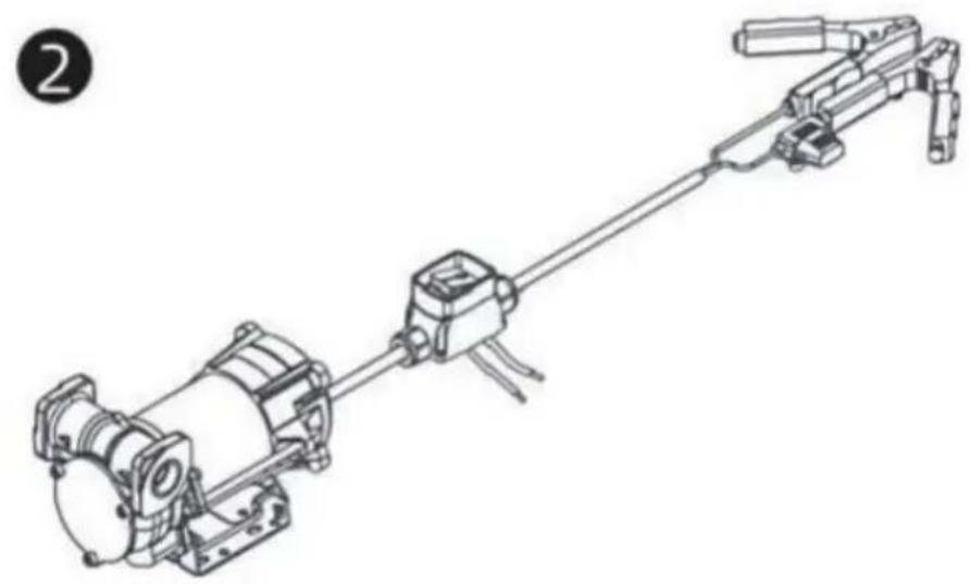
natural_image
Technical line drawing of a mechanical assembly with no visible text or symbols
natural_image
Technical line drawing of a mechanical device with no visible text or symbols
t is preferable to place Case Switch with pliers sheltered from atmospheric agents.
ts installation must be carried out by specialized personnel and carried out according to the instructions provided in this document


natural_image
Technical line drawing of a mechanical assembly with no visible text or symbols
natural_image
Technical line drawing of a mechanical assembly with a thumbs-up icon (no text or symbols on the diagram itself)
DANGER!
Fumes accumulated whilefueling create an Explosive Atmosphere. It is CRITICAL that all possible sources of ignition be removed to a safe distance or extinguished. Sources of ignition would include (but not be limited to) open flames, cigarettes, static discharge, or electrical connection that can create a spark. Explosion, fire, and severe injury or death will occur if the explosive vapors are ignited.
Fumes accumulated whilefueling create an explosive Atmosphere around the tank that is beingfiled Toavoidpossible explosion of accumulated vapors, it is critical to keep possible sources of spark/ignition at safe distances from the fuelvapors
The accompanying diagram shows minimum safe distances for safe fueling 3m is the minimum safe distance between.
-Power source, switch and fuel supply.
-Power source, switch and thank being filled.
-Power source, switch and pump.

flowchart
graph TD
    A["PUMP INLET SIDE TANK"] --> B["POWER CORD"]
    B --> C["SWITCH"]
    C --> D["FUSE 25A"]
    E["SIDE TANK"] --> F["2.5M MIN."]
    F --> G["3M MIN."]
    G --> H["Ground"]
WARNING
●STATIC EL ECTRIC SPARK EXPLOSION HAZARD
● NEVER fill portable containers that are in oron vehicl

natural_image
Symbolic icon depicting a person using a tool to lift a vehicle, enclosed in a circle with radiating lines (no text or symbols)● ALWAYS PLACE CONTAINERS ON GROUND
- Keep nozzle in contact with container while flli

Astatic electric sparkcanoccur when fling portable containers sitting ontruck bed liners, or on any vehicle' scarpeting orfloor mating. This spark will explosively ignite gasoline vapor hire and cause SERIOUSINJURY or DEATH
FCC Informatie:
YH CONSULTING LIMITED. C/O YH Consulting
Limited Office 147, Centurion House, London Road, Staines-upon-Thames, Surrey, TW18 4AX
| EC | REP |
E-CrossStu GmbH
Mainzer Landstr.69,
60329 Frankfurt am Main.

Technische ondersteuning en e-garantiecertificaat www.vevor.com/support
VEVOR
Affordable. Reliable. Home Improvement.
BÄRBAR DIESEL&BENSINTANK
MODELL: YDIES200L-E / YDIES400L-E
www.vevor.com/support t
VEVOR
Affordable. Reliable. Home Improvement.
PORTABLE DIESEI GASOLINE TAN
MODELL: YDIES200L-E / YDIES400L-E

natural_image
Two identical gray industrial electrical enclosures with visible wiring and components, no text or symbols present.Foto för referens
Operation and Installation
FÖRBEREDELSER DE ÖVERFÖRA ENHET FÖR DRIFT;
natural_image
Technical line drawing of a mechanical assembly (no text or symbols visible)ZON O
ZON 20
ZON 21
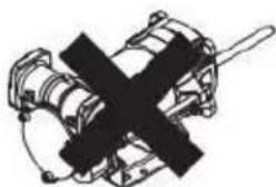
natural_image
Pure mechanical assembly diagram without any text, numbers, or symbolsINTENDED USE
| INTENDED USE | | PUMP FOR TRANSFERRING FUEL SUITABLE FOR OPERATING IN ZONESCLASSIFIED“1”AND “2”, ACCORDING TO DIRECTIVE 99/92/CE |
| THE DETERMINATION OF THE AREAS (ZONES) IS TO BE CARRIED OUT BY THE USER |
| FORBIDDEN USE | Using the appliance for fluids other than those listed at paragraph “Fluids permitted” and for uses other than those described at the item “authorised use” is forbidden. |
| PLANT OPERATION RESTRICTIONS IT IS FORBIDDEN: | |
| 1 | To use the appliance in a construction configuration other than that contemplated by the manufacturer |
| 2 | To use the appliance with fixed guards tampered with or removed. |
| 3 | To use the appliance in places where there is risk of explosion and/or fires classified in the following zones: 0; 20; 21; 22 |
| 4 | To integrate other systems and/or equipment not considered by the manufacturer in the executive project. |
| 5 | To connect the appliance up to energy sources other than those contemplated by the manufacturer |
| 6 | To use the commercial devices for purposes other than those indicated by the manufacturer. |
| 7 | To use in case of lightnings |
WARNING

INSTALL AWAY FROM STRONG ELECTROMAGNETIC FIELDS
HANDLING AND TRANSPORT
Due to the limited weight and dimensions of the pumps, special lifting equipment is not required to handle them. The pumps are carefully packed before dispatch. Check the packing when receiving the material and store in a dry place.
GENERAL WARNINGS
| Important precautions | To ensure operator safety and to protect the pump from potential damage, workers must be fully acquainted with this instruction manual before performing any operation. | |
| Symbols used in the manual | The following symbols will be used throughout the manual to highlight safety information and precautions of particular importance: | |
 | WARNING | WARNING indicates a hazardous situation which, if not avoided, could result in death or serious injury |
 | NOTICE | NOTICE is used to address pratics not related to personal injury |
| Manual preservation | This manual should be complete and legible throughout. It should remain available to end users and specialist installation and maintenance technicians for consultation at any time. | |
| NOTICE | | ALWAYS USETHE RIGHT VOLTAGES TO CONNECTTHE PUMPS |
| WARNING | | BEFORE PROCEEDING WITH THE REFUELLING OF AIRCRAFTS, ENSURE THAT THE SYSTEM INTENDED FOR SUCH ACTION COMPLIES WITH THE REGULATIONS IN FORCE IN THE COUNTRYOF USE |
| WARNING | | USE THE PUMP ONLYWITH EFLUIDS PERMITTEDDO NOT USE WITHFLUIDS NOT PERMITTED TOAVOID DAMAGING THE PUMP THE WARRANTYLAPSES IN CASE OF MISUSE OF THE FLUID. |
| DO NOT USE THE PUMP WITH LIQUID FOOD PRODUCTS AND/OR WATER-BASED FLUIDS. | ||
| DO NOT OPERATE THE PUMPDRYTO AVOID DAMAGE. | ||
| Before connection, make sure that the piping and the suction tank are free of dirt and solid residue that could damage the pump and its accessories. NEVER COLLECT THE FLUID FROM THE BOTTOM OF THE TANK SINCE IT MAY CONTAIN IMPURITIES | ||
| Keep a working fire extinguisher in the work area. | ||
| Do not operate the unit when fatigued or under the influence of drugs or alcohol. | ||
| Do not alter or modify equipment. Alterations or modifications may void agency approvals and create safety hazards | ||
| Keep children and animals away from work area. | ||
| Comply with all applicable safety regulations.Do not use in case of lightnings | ||

BEFORE USING THE PUMP SWITCH OFF ALL THE ELECTRONIC DEVICES(I.E. MOBILE PHONES,BEEPERS ETC.)
FIRST AID RULES
Contact with the product
Persons who have suffered electric shock
In the event of problems developing following EYE/SKIN CONTACT, INHALATION or INGESTION of the treated product, please refer to the SAFETY DATA SHEET of the fluid handled.
Disconnect the power source, or use adry insulator to protect yourself while you move the injured person away from any electrical conductor. Avoid touching the injured person with your bare hands until he is far away from any conductor. Immediately call or help from qualified and trained personnel. Do not operate switches with wet hands.
NOTICE

SMOKING PROHIBITED
Please refer to the safety data sheet for the product

GENERAL SAFETY RULES
USER'S RESPONSIBILITY

IT IS ESSENTIAL TO GET TO KNOW AND UNDERSTAND THE INFORMATION CONTAINED IN THIS MANUAL.
IT IS ESSENTIAL TO GET TO KNOW AND OBSERVE THE SAFETY SPECIFICATIONS FOR FLAMMABLE LIQUIDS.
BEFORE USING THE PUMP IT'S IMPORTANT TO TRAIN OPERATORS, INSTALLERS AND MAINTENANCE STAFF TO LETTHEM WORKINAPARTICULARAREA NO. 1AS MENTIONED BY DIRECTIVE 99/92/EC
| Essential protective equipment characteristics | In case of contact with theproduct and for good standard of behaviour,wear protective equipmentwhich is: .Suited to the operations that need to be performed .Resistant to products used To do so,please refer to the relevant technical datasheets of the fuid used. | ||
| Personal protective equipment that must be worn | | | |
| safety shoes | close-fiting | dofthing | |
| | ||
| Necessary safety devices | protection gloves | safety goggles | |
| instructions manual | ||
| Protective gloves | Prolonged contact with the treated product may cause skin irritation;always wear protective gloves during dispensing. | ||
| WARNING | ENFORCE REGULATIONS FOR ELECTRICAL INSTALLATIONALL WIRING AND ELECTRICAL CONNECTIONS MUST BE PERFORMED BY AUTHORIZED AND SUITABLY TRAINED PERSONNEL.Never touch the electric plug or socket with wet hands.Do not switch the dispensing system on if the network connection cable or important parts of the apparatus are damaged,such as the inlet/outlet pipe, nozzle or safety devices.Replace the damaged pipe immediately. | ||
| WARNING | The electrical connection between the plug and socket must be kept well away from waterTHE PUMP IS EQUIPPED WITH CURRENT-SENSING PROTECTION. IF IT ACTIVATES TURN OFF THE PUMP IMMEDIATELY. | ||
| WARNING | THE PUMP IS EQUIPPED WITH PROTECTION AGAINST OVERHEATING AND OVERLOAD RISKS. SHOULD SUCH DEVICES ACTIVATE, THE PUMP SHUTS DOWN AUTOMATICALLY, BUT THE MASTER SWITCH IS NOTTURNED OFF.IT IS IMPORTANT TO STOP THE PUMP USING ITS SWITCH. THE PUMP RESTARTS AFTER ITS NORMAL OPERATING CONDITIONS HAVE BEEN RESTORED. | ||
| WARNING | FAILURE TO OBSERVE THE ABOVE MENTIONED RULES CAN CAUSE SERIOUS ACCIDENTSSHOULD THE HEAT SENSOR ACTIVATE UNDER NORMAL USE CONDITIONS, PLEASE CONTACT THE TECHNICALSUPPORT | ||
| NOTICE | TO PREVENT ELECTRIC SHOCK AND DETONATION OF SPARKS, ALL PUMPING SYSTEM MUST HAVE PROPER GROUNDING, INCLUDING TANK AND ANY ACCESSORIES | ||
TECHNICAL DATA PERFORMANCE SPECIFICATIONS
The performance diagram shows flow rate as a function of back pressure.
| Absorption (A) | FlowRate (/min)-(gpm) | Back Pressure (bar)-(psi) | ||
| Functioning Point | ||||
| A = (Maximum Flow Rate) | 15 | 35-9 | 0,2 -3 | |
| C • (By-Pass) | 25 | 0 | 1] 6 | |
| ATTENTION | The curve refers to the following operating conditions:Fluid: PETROL,Temperature: 20°C Suction conditions: The pipe and the pump position relative to the fluid level is such that a low pressure of O.3 bar is generated at the nominal flow rate.Under different suction conditions higher low pressure values can be created that reduce the flow rate compared to the same back pressure values. To obtain the best performance, it is very important to reduce loss of suction pressure as much as possible by following these instructions:· shorten the suction pipe as much as possible· avoid useless elbows or throttling in the pipes· keep the suction filter clean· use a pipe with a diameter equal to, or greater than, indicated (see Installation). | |||
OPERATING CONDITIONS
ENVIRONMENTAL CONDITIONS
| AMBIENTTEMPERATUREFLUIDTEMPERATURERELATIVEHUMIDITY | min.+23°F/max+104°Fmin.-10°C/max+40C | |
| min.+23°F/max+104°Fmin.-10C7max+40C | ||
| max.90% | ||
| WARNING | | The temperature limits shown apply to the pump components and must be respected to avoid possible damage or malfunction. |
ELECTRICAL POWER SUPPLY
| NOTICE | | The pump must be powered by DC line, the nominal values of which are indicated on the table in the paragraph "ELECTRICAL DATA"The maximum acceptable variations from the electrical parametersare:Voltage: +/-5%of the EX30 nominal value+/-10%of the EX20 nominal valueFrequency:+/-2%of the nominal value |
| WARNING | | Power supply from lines with values that do not fall within the indicated limits could cause damage to the electrical and electronic components. |
DUTY CYCLE
| NOTICE | | In conditions of maximum T.Environment( 40^ c)and at the nominal transfer conditions:-The EX30 pumps have been designed for intermittent use and a 30 min duty cycle.ONand 60 min OFF-The EX20 pumps have been designed for operating conditions S1 |
| WARNING | | Functioning under by-passconditions is only allowed for short periods of time (max. 30 seconds). |
FLUIDS PERMITTED
| WARNING | | THE PUMP CAN BE USED -DIESEL -KEROSENE -PETROL -AVGAS -PETROLALCOHOL 100/100LL (pump) | ONLYWITH THE FOLLOWING FLUIDS: | |||
| MIXED MAX15% only)-JETA/A1 (pump only) | ||||||
| -ASPEN2/4 | ||||||
INSTALLATION
| WARNING | | BEFOREANYOPERATION, ENSURE TO BE OUT OFPOTENTIALLYEXPLOSIVE AREAS |
| The pump must never be operated before the delivery and suction lines have been connected |
PRELIMINARY -Verify that all components are present. Request any missing parts from the manufacturer INSPECTION -Check that the pump has not suffered any damageduringtransport or storage.
-Carefullyclean the suction and delivery inlets and outlets, removing any dust or other packaging material that may be present.
Check that the electrical data corresponds to those indicated on the data plate
-Always install in anilluminated area.
Install the pump at a height of min. 80 cm
| WARNING | | IF VALVES IN THE CIRCUIT ARE TO BE INSTALLED,MAKE SURE THEY ARE EQUIPPED WITH OVERPRESSURE SYSTEM. | ||||||||
| CLEAN | THE | TANK | AND | MAKE | SURE | IT | IS | WELL- | ||
| VENTILATED (RECOMMENDED) | OPENING | PRESSURE:3psi | ||||||||
| WARNING | | DO NOT BLOCK THE DRAINAGE HOLES | ||||||||
POSITIONING, CONFIGURATIONS AND ACCESSORIES
| NOTICE | | The pump must be secured in a stable manner. |
| WARNING | | It is the installer's responsibility to provide the line accessories necessary for the safe and proper functioning of the pump. The accessories that are not suitable to be used with the previously indicated material could damage the pump and/or cause injury to persons, as well as causing pollution. |
| To maximise performance and prevent damage that could affect pump operation, always demand original accessories. | ||
NOTES ONSUCTIONAND DELIVERY LINES
DELIVERY
The selection of the pump model must be made taking into account the characteristics of the system
The combination OF:thelength of the pipe, the diameter of thepipe, as well as the accessories installed, could create back pressure that are greater than the maximum predicted pressure, thereby causing the pump's electronic controls to intervene and reducing the dispensed flow considerably.
In these cases, to guarantee correct operation of the pump, it is necessary to reduce the resistance of the system using pipes that are shorter or that have a greater diameter, as well as line accessories with smaller resistances (e.g. an automatic dispensing nozzle with greater flow rate capacity)
SUCTION
Self-priming pumps are characterized by excellent suction capacity.
During the start-up phase, when the suction pipe is empty and the pump is wet with the fluid, the electric pump unit is able to suck liquid from a maximum vertical distance of 2m
It is important to note that it could take up to 1 minute for the pump to prime and that the presence of an automatic dispensing nozzle on the delivery side will prevent the air trapped during the installation from being released and, therefore, the correct priming of the pump. For this reason, it is always advisable to prime the pump without an automatic delivery nozzle, verifying the proper wetting of the pump
Always install a foot valve to prevent the suction pipe from being emptied and to keep the pump wet at all times In this way, the pump will always start up immediately the next times it is used. When the system is in operation, the pump can operate with back pressures of up to 05 bars on the suction inlet; beyond this point, the pump may begin to cavitate resulting in a drop of the flow rate and an increase in the noise levels of the system.
In light of this, it is important to guarantee small back pressures on the suction side, by using short pipes with diameters that are equal to or larger than those recommended, reducing bends to a minimum, and using filters with a large cross-section and foot valves with minimum possible resistance on the suction side. It is very important to keep the suction filters clean because, when they become clogged, they increase the resistance of the system
The vertical distance between the pump and the fluid must be kept as short as possible, and it must fall within the 2m maximum required for priming. If the distance is greater, a foot valve must be installed to allow the suction pipes to fill up and the diameter pipes must be larger. It is however recommended that pump not be installed if the vertical distance is greater than 3m.
| WARNING | If the suction tank is higher than the pump, an anti-siphon valve should be installed to prevent accidental diesel fuel leaks. Dimension the installation in order to controlthebackpressures due towater hammering |
| It is a good system practice to install vacuum and air pressure gauges right at the inlets and outlets of the pump, which allow verification that operating conditions are within anticipated limits. To prevent the suction pipes frombeing emptied when the pump stops, a foot valve should be installed. | |
| THE INSTALLER IS RECOMMENDED TO INSTALLASUCTION FILTER. | |
CONNECTIONS
ELECTRICAL CONNECTIONS
| WARNING | | BEFORE ANYOPERATION, ENSURE TO BE OUT OF POTENTIALLYEXPLOSIVE AREAS |
| IT IS THE INSTALLER'S RESPONSIBILITY TO CARRY OUT THE ELECTRICAL CONNECTIONS IN COMPLIANCE WITH THE RELEVANT STANDARDS. | ||
| NOTICE | | BLACK CABLE: “■” (negative pole)RED CABLE: “+” (positive pole) |
| WARNING | | DO NOT CUT THE CABLE FOR ANY REASON |
| WARNING | | Comply with the following (not exhaustive)instructions to ensure a proper electrical connection: |
During installation and maintenance make sure that power supply to the electric lines has been turned off. -Use cables with minimum sections, rated voltages and installation type that are suitable for the characteristics indicated in paragraph "ELECTRICAL DATA" and the installation environme nt. -Always make sure that the cover of the terminalstrip box is closed before switching on the power supply, after having checked the integrity of the seal gaskets that ensure the IP55 protection grade. For those screws use a 10 nm clamping couple
| WARNING | | All motors are equipped with a grounding terminal.Make sure all the plantis properly grounded. |
| NOTICE | | IN THE EVENT OF INSTALLATION IN ZONES WHICH ARE NOT CLASSIFIED, ITIS SUFFICIENT TO OBSERVE THE MINIMUM SAFETY STANDARDS ALREADYMENTIONED IN THIS MANUAL. |
| WARNING | | -THE OWNER HAS THE RESPONSIBILITY TO VERIFY THAT ALL THE LOCALAND NATIONAL REGULATIONS HAVEBEEN OBSERVED.-MAKE SURE THAT THE CABLE CONNECTING THE BATTERY IS PROTECTEDFROM HEAT SOURCES AND SHARP EDGES. INSTALL THE FUSE CLOsertoTHE BATTERY. |
| WARNING | | FAILURE TO OBSERVE THE ABOVE MENTIONED RULES CAN CAUSE SERIOUSACCIDENTS |
| WARNING | | IN CASE THE ELECTRICAL CABLING IS IN CLASSIFIED AREA, A CABLINGWITH PROTECTION DEGREESUITABLE TO THE WORKING AREA SHOULD BEPERFORMED. |
| WARNING | | PREVENT THE INSTALLATION OF ASTOP BUTTON INA REACHABLE POSITIONANDWITHADEGREEOFPROTECTIONSUITABLEFOR THE CLASSIFICATIONOFTHE PUMP ONWHICH ITIS INSTALLED. |
PIPING CONNECTIONS
| FOREWORD | -Before carrying out any connection, refer to the visual indications ie arrow on the pump head, to identify suction and delivery |
| WARNING | Wrong connection can cause serious pump damage. |
| PRELIMINARY INSPECTION | Before connection, make sure that the piping and the suction tank are free of dirt and solid residue that could damage the pump and its accessories. NEVER COLLECT THE FLUID FROM THE BOTTOM OF THE TANK SINCEIT MAY CONTAIN IMPURITIES- Before connecting the delivery pipe, partially fill the pump body, from delivery side, with the liquid that needs to be pumped in order to facilitate priming.- Do not use conical threaded fittings, which could damage the threaded inlet or outlet openings of the pump if excessively tightened. |
INITIAL START-UP
| FOREWORD | Check that the quantity of fluid in the suction tank is greater than the amount you wish to transfer.-Makesure that the residual capacity of the delivery tank is greater than the quantity you wish to transfer.-Make sure that the piping and line accessories are in good condition. |
| NOTICE | THIS PUMP IS NOT PROVIDED FOR FURTHER REGULATION OF DELIVERY AND PRESSURE |
| WARNING | Fluid leaks can damage objects and injure persons. |
| NOTICE | -Never start or stop the pump by connecting or cutting out the power supply.-Prolonged contact with some fluidscan damage the skin.The use of goggles and glovesis recommended. |
| IF THE PUMP DOES NOT PRIME | Depending on the system characteristics,the priming phase can last from several seconds to a few minutes.If thisphase is prolonged,stop thepump and verify:-that the pump is not running completelydry (fill with fluid from thedelivery line);-that the suction pipe guarantees against air infiltration;that the suction filter is not clogged;that the suction height is not higher than 2 mt.that all air has been released from the delivery pipe. |
| AT THE END OF THE INITIAL START-UP | When priming has occurred,verify that the pumpis operating within the anticipated range,in particular:-that under conditions of maximum back pressure,the powerabsorption of the motor stays within the values shown on the identification plate;that the delivery back pressure does not exceed the maximum back pressure for the pump |
EVERYDAY USE
USE PROCEDURE
1 Inflexible pipes are used, attach the ends of the piping to the tanks. In the absence of an appropriate slot, solidly grasp the delivery pipe before beginning dispensing.
2 Before starting the pump make sure that the delivery valve is closed (dispensing nozzle or line valve) or make sure that the delivery pipe is properly inserted inside the destination tank.
3 Turn the ON/OFF switch on
4 Open the delivery valve, solidly grasping the pipe
5 While dispensing.do not inhale the pumped product
6 If any treated fluid leaks out during dispensing, take all steps necessary to ensure the leaked fluid is cleaned up and safe as specified on the product technical sheet.
7 Close the delivery valve to stop dispensing and switch off the pump, or switch off the pump and then close the delivery valve
| WARNING | | THE WORKING OPERATIONS MUST ALWAYS BE GUARDED BY THI OPERATOR. |
| The by-pass valve allows functioning with delivery closed only for short periods (max. 3 minutes) | ||
| To avoid damaging the pump, after use, make sure the pump is off. | ||
| In case of a power break, switch the pump off straight away. | ||
| Should any sealants be used on the suction and delivery circuit of the pump make sure that these products are not released inside the pump. | ||
| Foreign bodies in the suction and delivery circuit of the pump could cause malfunctioning and breakage of the pump components. |
M△INTEN△NCE
Safety instructions The pump is designed and constructed to require a minimum of maintenance. Before carrying out any maintenancework,disconnect the pump from any electrical and hydraulic power source. During maintenance,the use of personal protective equipment (PPE)is compulsory. In any case always bear in mind the following basic recommendationsfor a goodfunctioning of the pump
| WARNING | | BEFORE ANYOPERATION, ENSURE TO BE OUTOF AREAS FOR SAFETY REASONS IT'S NOTALLOWEDTO PARTS: (1) BOTTOM (2) MOTOR PIPE(3) PUMP BODY | POTENTIALLYEXPLOSIVE DISASSEMBLE THESE | ||||||
| FOR SAFETY REASONS IT IS FORBIDDEN TO REMOVE PLATE" (1), "MOTOR TUBE" (2) AND "FRONT SHIELD" (3). | THE PARTS | "BOTTOM | |||||||
| Authorised maintenance personnel | All maintenance must be performed by qualified personnel.Tampering can lead to performance degradation,danger topersons and/or propertyand may resultin the warranty and UL/ATEXCERTIFICATION being voided. |
| Measures to be taken | Check that the labels and plates found on the dispensing system do not deteriorate or become detachedover time. |
| ONCEAWEEK: | -Check that the pipe connections are not loose to prevent any leaks;-Check and keep the filter installed on the suction line clean. |
| ONCE A MONTH: | -Check the pump body and keep it clean and free of any impurities;-Check that the electrical supply cables are in good condition. |
NOISE LEVEL
Under normal operating conditions, noise emission of all models does not exceed 74dB at a distance of 1 metre from the electric pump.
PROBLEMS AND SOLUTIONS
For any problems contact the authorised dealer nearest to you.
| PROBLEM | POSSIBLE CAUSE | CORRECTIVE ACTION |
| THEMOTOR IS NOT TURNING | Lackof electric power | Check the electrical connections and the satety systems |
| Rotor jammed | Check for possible damage or obstruction of the rotating components. | |
| Motor problems | Contact the Service Department | |
| THE MOTOR TURNS SLOWLY WHEN STARTING | Low voltage in the electric power line | Bring the voltage back within the anticipated limits |
| LOWOR NO FLOWRATE | Low level in the suction tank | Refill the tank |
| Foot valve blocked | Clean and/or replace the valve | |
| Filter clogged | Clean the filter | |
| Excessive suction pressure | Lower the pump with respect to the level of the tank or increase the cross-section of the piping | |
| High loss of head in the delivery circuit (working with the by-pass open) | Use shorter piping or of greater diameter | |
| By-pass valve blocked | Dismantle the valve, clean and/or replace it | |
| Air entering the pump or the suction piping | Check the seals of the connections | |
| A narrowing in the suction piping | Use piping suitable for working under suction pressure | |
| Low rotation speed | Check the voltage at the pump. Adjust the voltage and/or use cables of greater cross-section | |
| The suction piping is resting on the bottom of the tank | Raise the piping | |
| INCREASED PUMP NOISE | Cavitation occurring | Reduce suction pressure |
| Irregularfunctioning of the by-pass | Dispense until the air is purged from the bypass system | |
| Presence of air in the fluid | Verify the suction connections | |
| LEAKAGE FROM THE PUMP BODY | Seal damaged | Check and replace the seal |
| THE PUMP DOES NOT PRIME THE LIQUID | Suction circuit blocked | Remove the blockage from the suction circuit |
| Malfunction of foot valve fitted on suction circuit | Replace foot valve | |
| The suction chambers are dry | Add liquid from pump delivery side | |
| The pump chambers are dirty or blocked | Remove the blockages from the suction and delivery valves | |
| THE HEAT SENSOR ACTIVATES UNDER NORMAL OPERATING CONDITIONS | Operating fault | Contact the technical support |
DEMOLITION AND DISPOSAL
Foreword
Disposing of packing materials Metal Parts Disposal Disposal of electric and electronic components

Information regarding the environment for clients residing within the European Union
Miscellaneous parts disposal
If the system needs to be disposed, the parts which make it up must be delivered to companies that specialize in the recycling and disposal of industrial waste and, in particular: The packaging consists of biodegradable cardboard which can be delivered to companies for normal recycling of cellulose.
Metal parts, whether paint-finished or in stainless steel, can be consigned to scrap metal collectors. These must be disposed of by companies that specialize in the disposal of electronic components, in accordance with the indications of directive 2012/19/UE (see text of directive below).
European Directive 2012/19/UE requires that all equipment marked with this symbol on the product and/or packaging not be disposed of together with non-differentiated urban waste. The symbol indicates that this product must not be disposed of together with normal household waste. It is the responsibility of the owner to dispose of these products as well as other electric or electronic equipment by means of the specific refuse collection structures indicated by the government or the local governing authorities.
Disposing of RAEE equipment as household wastes is strictly forbidden. Such wastes must be disposed of separately.
Any hazardous substances in the electrical and electronic appliances and/or the misuse of such appliances can have potentially serious consequences for the environment and human health.
In case of the unlawful disposal of said wastes, fines will be applicable as defined by the laws in force.
Other components, such as pipes, rubber gaskets, plastic parts and wires, must be disposed of by companies specialising in the disposal of industrial waste.
HÅLLBRYTARE MED TÅNG FÖR BRÄNSLETANKENS PUMP

THESWTCH HAS NOT BEEN DESIGNED IN COMPLIANCE WITH ATEX REGULATION OR TO OPERATE IN ENVIRONMENTS WITH POTENTIALLY EXPLOSIVE ATMOSPHERE.
DO NOT INSTALL IN POTENTIALLY EXPLOSIVE LOCATIONS.
natural_image
Diagram of a mechanical assembly with an arrow indicating motion, showing a motor, gear, and shaft (no text or labels)
natural_image
Technical line drawing of a mechanical assembly with no visible text or symbols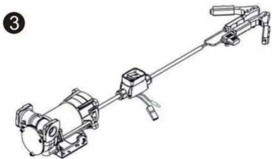
natural_image
Technical line drawing of a mechanical device with articulated arms and housing (no text or symbols)
t is preferable to place Case Switch with pliers sheltered from atmospheric agents.
ts installation must be carried out by specialized personnel and carried out according to the instructions provided in this document


natural_image
Technical line drawing of a mechanical assembly with no visible text or symbols
natural_image
Technical line drawing of a mechanical assembly with a thumbs-up icon (no text or symbols on the diagram itself)
DANGER!
Fumes accumulated whilefueling create an Explosive Atmosphere. It is CRITICAL that all possible sources of ignition be removed to a safe distance or extinguished. Sources of ignition would include (but not be limited to) open flames, cigarettes, static discharge, or electrical connection that can create a spark. Explosion, fire, and severe injury or death will occur if the explosive vapors are ignited.
Fumes accumulated whilefueling create an explosive Atmosphere around the tank that is beingfiled Toavoidpossible explosion of accumulated vapors, it is critical to keep possible sources of spark/ignition at safe distances from the fuelvapors
The accompanying diagram shows minimum safe distances for safe fueling 3m is the minimum safe distance between.
-Power source, switch and fuel supply.
-Power source, switch and thank being filled.
-Power source, switch and pump.

flowchart
graph TD
    A["PUMP INLET SIDE TANK"] --> B["POWER CORD"]
    B --> C["SWITCH"]
    C --> D["FUSE 25A"]
    E["SIDE TANK"] --> F["2.5M MIN."]
    F --> G["3M MIN."]
    G --> H["Ground"]
WARNING
●STATIC EL ECTRIC SPARK EXPLOSION HAZARD
● NEVER fill portable containers that are in oron vehicl

natural_image
Symbolic icon depicting a person using a tool to lift a vehicle, enclosed in a circle with radiating lines (no text or symbols)● ALWAYS PLACE CONTAINERS ON GROUND
- Keep nozzle in contact with container while flli

Astatic electric sparkcanoccur when fling portable containers sitting ontruck bed liners, or on any vehicle' scarpeting orfloor mating- This spark will explosively ignite gasoline vapor hire and cause SERIOUSINJURY or DEATH
FCC Information:
YH CONSULTING LIMITED. C/O YH Consulting
Limited Office 147, Centurion House, London
Road, Staines-upon-Thames, Surrey, TW18 4AX
| EC | REP |
E-CrossStu GmbH
Mainzer Landstr.69,
60329 Frankfurt am Main.

www.vevor.com/support