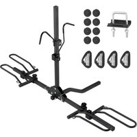
RC-1803J - Bike rack Vevor - Free user manual and instructions
Find the device manual for free RC-1803J Vevor in PDF.


| Brand | Vevor |
| Model | RC-1803J |
| Product Type | Hitch Mount Bike Rack |
| Bike Capacity | 2 bikes |
| Maximum Load | 36 kg (80 lb) |
| Compatible Vehicle Types | Car, SUV, Truck, Trailer |
| Bike Compatibility | Most bikes (frame up to 60 mm wide) |
| Hitch Size | 1.25 inch / 2 inches |
| Color | Black |
| Main Material | Steel |
| Overall Dimensions (approx.) | Not specified in the manual |
| Net Weight | Not specified in the manual |
| Main Features | Bike support on hitch, foldable arms, frame hooks, fixing straps, release for trunk access |
| Maintenance and Cleaning | Clean with water-soluble detergents; lubricate screws and nuts regularly; store in a cool, dry place |
| Safety | Observe speed limits (max 120 km/h), check fastenings before each trip, do not exceed max load, use safety strap |
| Spare Parts | Available via packing list (e.g., tubes, hooks, straps, hardware) |
| Repairability | Yes, assembly with standard screws, replaceable parts |
| Warranty | Technical support and electronic warranty certificate at www.vevor.com/support |
| General Information | User manual included, model RC-1803J, brand Vevor |
Frequently Asked Questions - RC-1803J Vevor
User questions about RC-1803J Vevor
0 question about this device. Answer the ones you know or ask your own.
Ask a new question about this device
Download the instructions for your Bike rack in PDF format for free! Find your manual RC-1803J - Vevor and take your electronic device back in hand. On this page are published all the documents necessary for the use of your device. RC-1803J by Vevor.
USER MANUAL RC-1803J Vevor
Technical Support and E-Warranty Certificate www.vevor.com/support
HITCH BIKE RACK
MODEL: RC-1803J
We continue to be committed to provide you tools with competitive price. "Save Half", "Half Price" or any other similar expressions used by us only represent of savings you might benefit from buying certain tools with us compared top brands and does not necessarily mean to cover all categories of tools offered are kindly reminded to verify carefully when you are placing an order with us actually saving half in comparison with the top major brands.
VEVOR®
TOUGH TOOLS, HALF PRICE
HITCH BIKE RACK
MODEL: RC-1803J
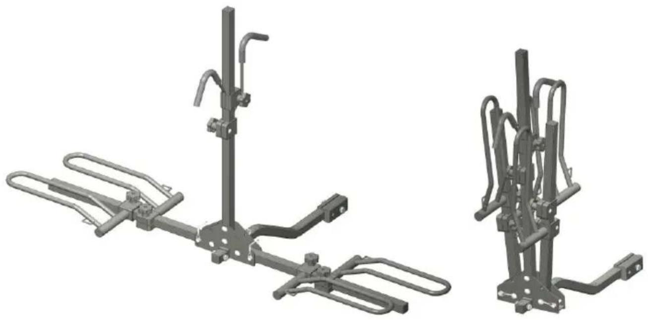
natural_image
Technical illustration of two mechanical device assemblies with articulated arms and mounting brackets (no text or symbols)NEED HELP? CONTACT US!
Have product questions? Need technical support? Please feel f contact us: Technical Support and E-Warranty Certificate www.vevor.com/support
This is the original instruction, please read all manual instruction carefully before operating. VEVOR reserves a clear interpretation user manual. The appearance of the product shall be subject to product you received. Please forgive us that we won't inform you there are any technology or software updates on our product.

Warning-To reduce the risk of injury, users must read instructions manual carefully.
PRODUCT PAREMETERS
| Model | RC-1803J |
| Capacity (Bicycles) | 2 |
| Maximum Load | 80 lbs |
| Vehicle Service Type | Car, SUV, Truck, Trailer |
| Applicability(Bicycles) | Most Bikes(Up to 60mm bicycle type width) |
| Mounting Size | 1.25 inch/2 inch |
| Color | Black |
PACKING LIST
When unpacking this product, check to make sure the parts listed below are included and carefully inspect for any damage that may have occurred during transit. If any part is missing or damaged, do not attempt to assemble or use product.
| NO | PICTURE | PART NUMBER | QTY | NO | PICTURE | PART NUMBER | QTY |
| A | 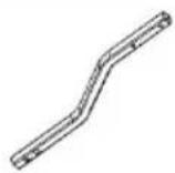 | Support tube(30*30*680) | 1 | B | 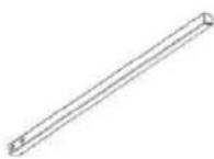 | Vertical pipe(30*30*850) | 1 |
| C | 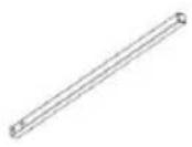 | Transverse tube30 * 30 * 6 | 2 | D | 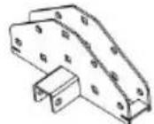 | Connecting seat | 1 |
| E | 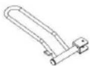 | Wheel frame-01 | 2 | F | 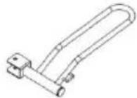 | Wheel Frame-02 | 2 |
| G | 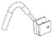 | Frame hook-01 | 1 | H | 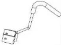 | Frame hook-02 | 1 |
| I |  | Bandage25*5 00 | 4 | J | 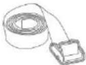 | Bandage25*2 500 | 1 |
| K | 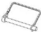 | Safety pin | 3 | L |  | Knob nut M8 | 6 |
| M | 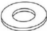 | Flat washer M10 | 12 | N | 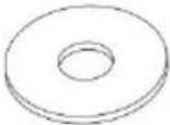 | Flat washer M8*25 | 6 |
| O | 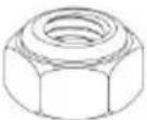 | Locknut M10 | 5 | P | 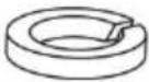 | Spring washer M8 | 6 |
| Q | 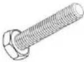 | Outer hexagonal bolt M10*50 | 5 | R | 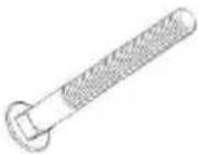 | Square neck bolt M8*70 | 6 |
| S | 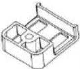 | Plastic clamp block | 12 | T | 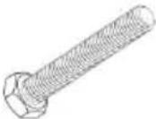 | Outer hexagonal bolt M12*75 | 1 |
| U | 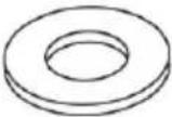 | Flat washer M12 | 2 | V | 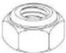 | Lock nut M12 | 1 |
| W | 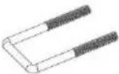 | Pressing plate screw M10 | 1 | X |  | Pressing plate | 1 |
| Y |  | Spring washer M10 | 2 | Z | 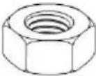 | Hexagon nut M10 | 2 |
| AA | 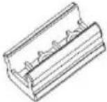 | Support pipe connections | 1 | AB |  | Small Rope | 8 |

Read these instructions carefully and retain them for future use. If the product is passed to a third party, then these instructions must be included.
When using the product, basic safety precautions should always be followed 1 reduce the risk of injury including the following:

DANGER
Risk of accidents!
- Any rear overhang on a vehicle must not exceed 60% of the wheelbase c 12.14 ft (3.7 m), whichever is less.
- The maximum dimensions for any vehicle, including its load, are 8.2 ft (2.5 in width and 14 ft(4.3 m) in height. A vehicle fitted with a bicycle carrier, with any bicycles must not exceed these limits.(Take into consideration the proportionality of the load to the vehicle size.)
- When installed with this product, the vehicle's speed must under no circumstances exceed 75 mph (120 kph). Always observe applicable speed limits and other traffic regulations.

WARNING
Risk of damage!
- When the product is installed, with or without bicycles loaded, collision, damage to property and/or personal injury may result. Beware of the increase dimensions (length/ width/height) of the vehicle before reversing and driving into garages, closed parking lots, a car wash, under bridges, subways or tunnels.
- Failure to properly install this product and/or load the bicycles onto the pro may cause damage to the vehicle and/or the bicycles, and may result in personal injury.
- Off-road driving is not recommended especially when the product is loaded. This may result in damage to the vehicle, bicycles or the product.
Road Safety
CAUTION
Risk of accidents!
- Sudden brakes, abrupt starts and sharp turns must be avoided as much as possible.
- The maximum speed of driving over speed bumps must not exceed 6.2 mJ (10 kph).
- If it is not possible to stay within the 3.94 ft (1.2 m) limit beyond the rear vehicle, a warning signal must be carried on the outermost part of the bid
- A warning signal must be, during the day, a brightly colored flag or piece material, with each side at least 12" (30 cm) long, and; if driving at nigh light that can be seen for at least 656 ft (200 m).
- Once the product is fitted, navigating parameters ( bends and braking) of the vehicle changes, especially when it is loaded (in particular crosswind sensitivity). Driving routines should be adjusted. The vehicle's driving characteristics and braking behavior change when loads are carried on the product.
- When carrying loads on the product, the driving speed has to be adjusted according to outside conditions such as road surfaces, side winds, general traffic situations, etc. It is recommended to keep to the applicable speed line for any road!
- Disable the automatic tailgate opening system when using this product if the vehicle is equipped with this function. Operate the tailgate manually.
- Open the tailgate according to the instructions when bicycles are loaded on product.
Product Safety
- Assembly must be carried out according to the instructions.
- Keep children and pets away while assembling the product.
- Do not use this product if any parts are missing, damaged, or worn.
-
This product should be installed, maintained and operated only by an experienced adult. If in doubt, consult a professional.
-
This product is designed such that, with proper assembly, mounting and operation cause no damage to the vehicle.
- Do not over-tighten the fasteners.
- This product is designed to be fitted directly on a vehicle and has a 2-inch hitch.
- This product is not designed to resist extreme weather conditions, especially seacoast air.
NOTICE
- Check the clearance. It is the responsibility of the driver to ensure there is sufficient clearance. This is dependent on the vehicle, the load, and the rear clearance should allow for the distance away from the rear wheels and the movements imposed by driveway ramps and speed bumps. It should be between 12" and 15" (30 and 38 cm).
- Do not use this product for purposes other than carrying bicycles. Do not modify any components of the product.
- Do not exceed the maximum load capacity, or carry more bicycles than recommended for each model.
- Always use the safety strap to attach the bicycles to this product. Replace safety strap at the first sign of wear.
- Ensure there is a safe distance between the bicycles and the ground, especially when entering a driveway. This product is for carrying standard-b frames. Do not transport tandem or recumbent bicycles.
- Do not transport bicycles with attachments such as baby seats, panniers, wheel covers, full bicycle covers, or motors.
- All loose or removable parts and accessories of bicycles (e.g. toolbars, baby carriers, pumps, etc.) must be removed before loading onto this product.
- Do not let children climb on or play with the product.
- For fuel economy and the safety of other road users, this product must be dismantled from the vehicle when not in use.
- Keep a safe distance between the exhaust pipe and the bicycle(s) so that exhaust heat cannot affect the bicycle(s) or the straps. Make sure bike tire
not directly behind the exhaust pipe.
- Use extra protections to protect the bicycles and the tailgate from scratches necessary.
- Always position the biggest/heaviest bicycle closest to the vehicle first, and then place others outwards in order of size.
- The vehicle should be in good condition in the area it which the product located.
- Do not mount to any type of trailer or RV, including Class B vehicles.
Inspection
- Regularly examine the product for corrosion, wear and tear. Stop using the product at the first sign of damage or if parts become detached.
- Regularly ensure that all hardware, screws, strap, knobs, and hubs of this product are securely tightened.
- After each new installation of this product on the vehicle and after each n loading, the product and loads must be checked after a short driving time (maximum 30 minutes on a bad road or 31.1 mi(50 km) on a normal road re-tightened if necessary.
- The screw connections between this product and the vehicle must be checked for a firm seat at regular intervals - at the latest after every 310.7 mi (5 and tightened if necessary, particularly during longer journeys. In case of road conditions, the check of the screw connections should be repeated every 2 hours.
- Before any journey, all connections of the screws, the basic rack and attachments, and other supports must be checked for firmness and tightness Tighten if necessary.
- After breaks, during which the vehicle with this product is left without supervision, all accessible fastenings of the product and the load must be checked for strength and functionality (examination for harmful external influences)!
Before First Use
- Check the product for transport damages.
- Remove all the packing materials.
- Clean the vehicle before installation, especially those parts that come into contact with this product.
- Clean the surface of this product before installing this product.
INSTALLATION INSTRUCTION
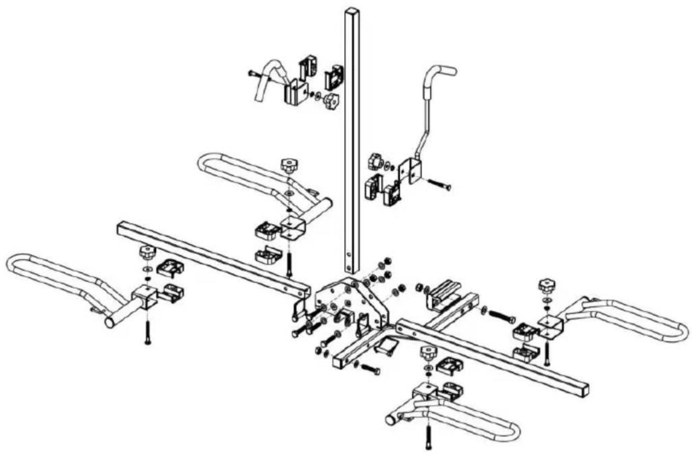
natural_image
Exploded view diagram of a mechanical assembly with no visible text or symbolsRequired tools:
1× Protective Gloves
1× 200mm Adjustable Spanner
1. Assembly Procedures
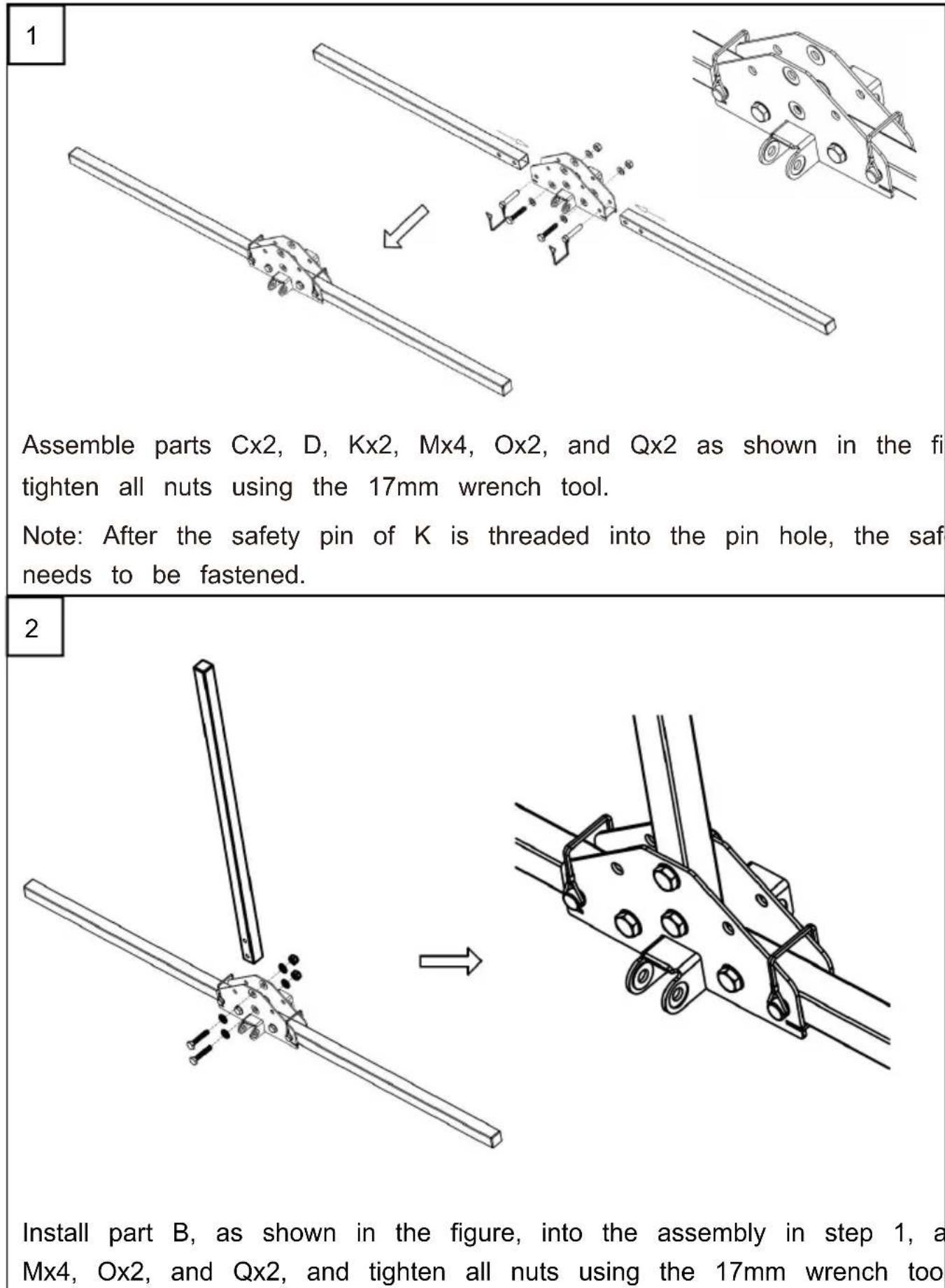
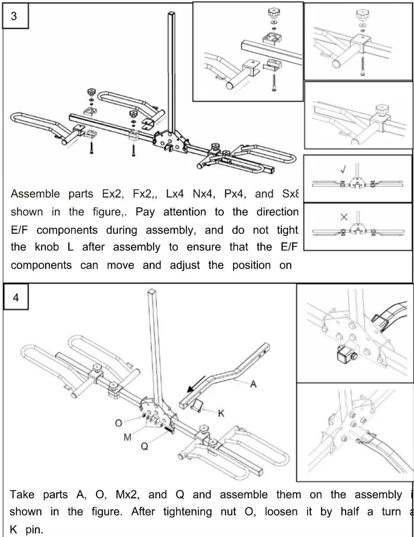
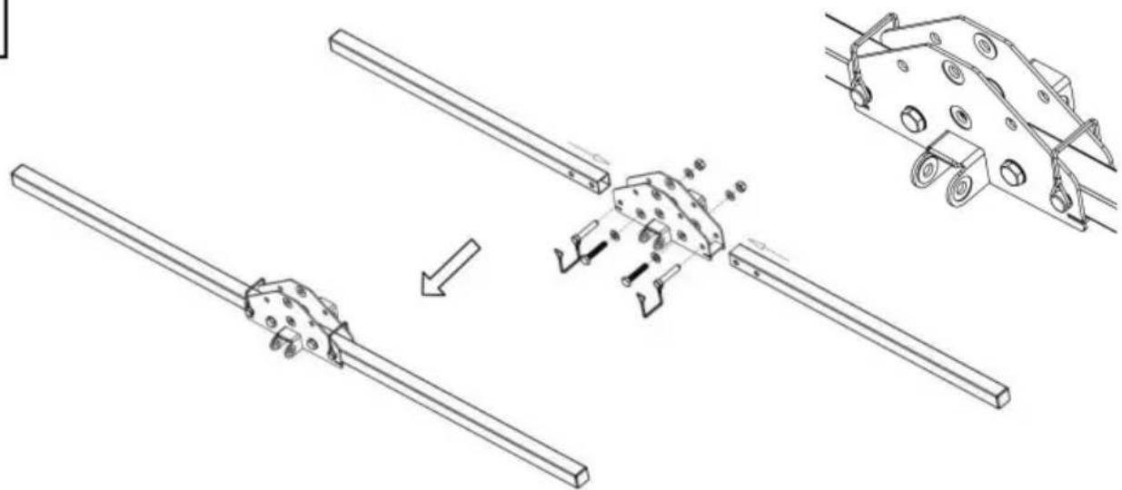
Take parts A, O, Mx2, and Q and assemble them on the assembly i shown in the figure. After tightening nut O, loosen it by half a turn a K pin.

2. Installation Procedures
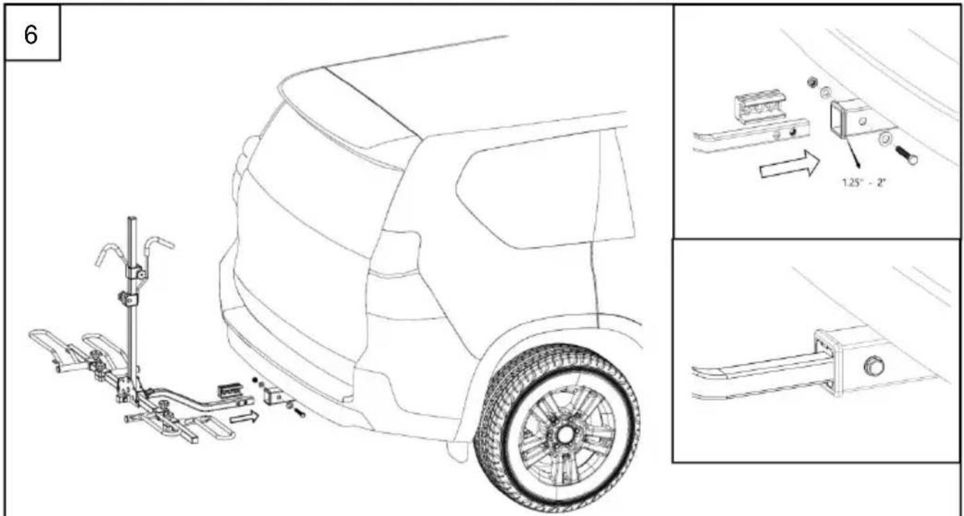
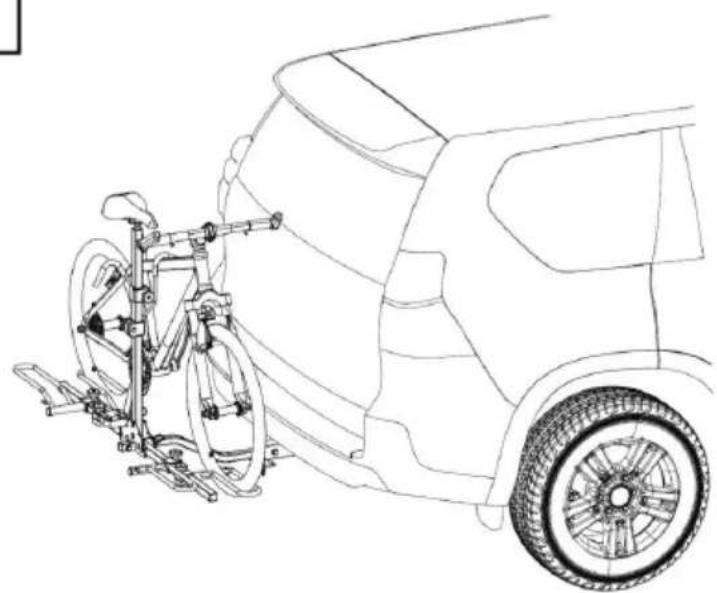
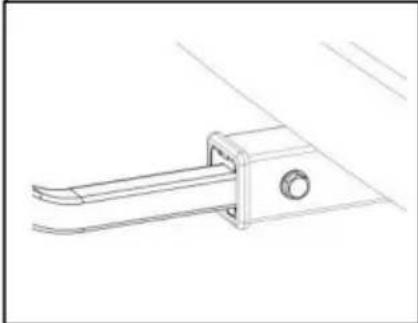
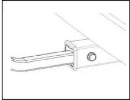
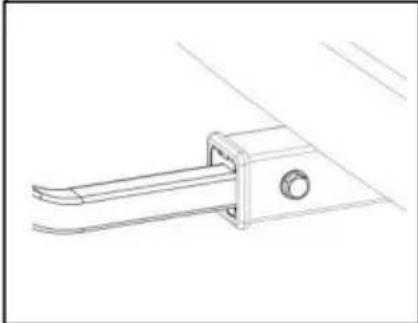
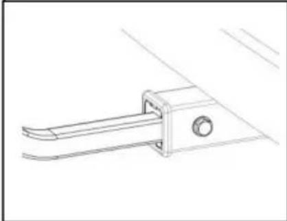
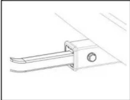
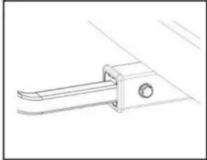
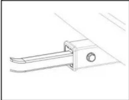
Insert the parts of AA laterally into the product in step 5, as shown in and install them onto the fixing bracket at the rear of the car. Tighten V parts and ensure that the T bolt parts are tightened using a wrench
7
natural_image
Line drawing of a car's rear suspension system with support structure (no text or symbols)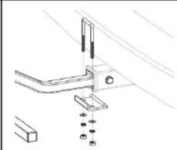
natural_image
Technical line drawing of a mechanical assembly with mounting brackets and fasteners (no text or symbols)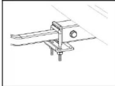
natural_image
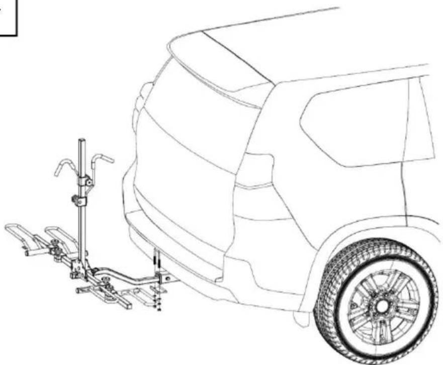
Technical line drawing of a mechanical clamp or bracket assembly (no text or symbols)After completing step 6, take the M, W, X, Y, and Z accessories as figure for clearance assembly, ensuring that the Z parts are tightened with wrench tool.
8
natural_image
Line drawing of a bicycle mounting onto a car, showing front wheel and rear wheel assembly (no text or symbols)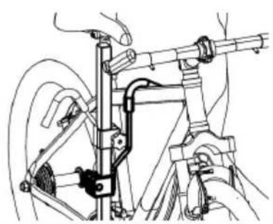
natural_image
Technical line drawing of a bicycle suspension system with hand and wheel assembly (no text or labels)Roughly adjust the distance between the E and F wheel frames according to actual wheel base of the front and rear wheels of the bicycle. First, pla bicycle on the inner side of the frame as shown in the figure, and fix onto the crossbeam of the bicycle. Fine adjust the distance between E that the wheels just fall into the wheel frame, and tighten the locking k and H.
9
natural_image
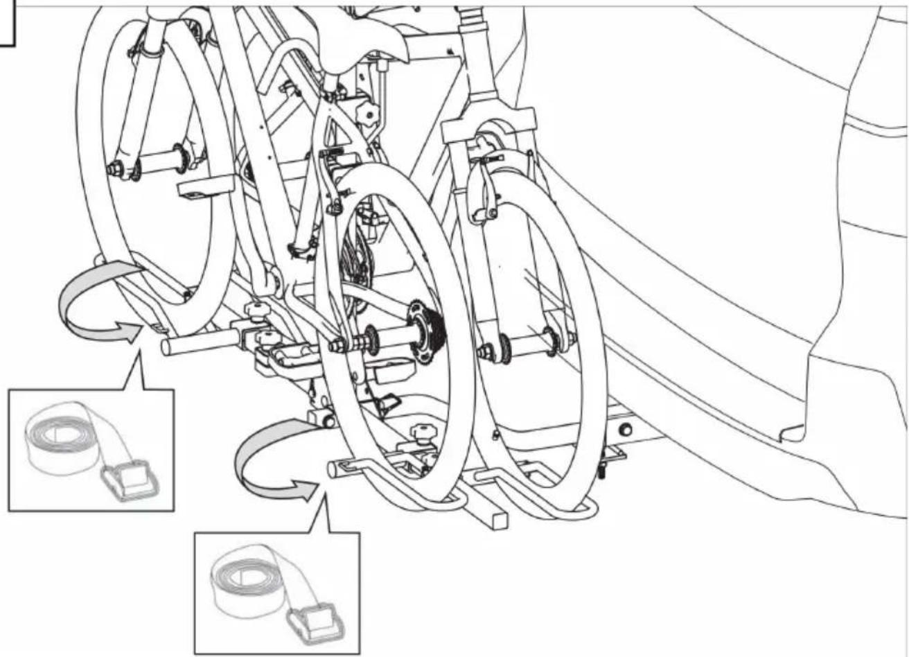
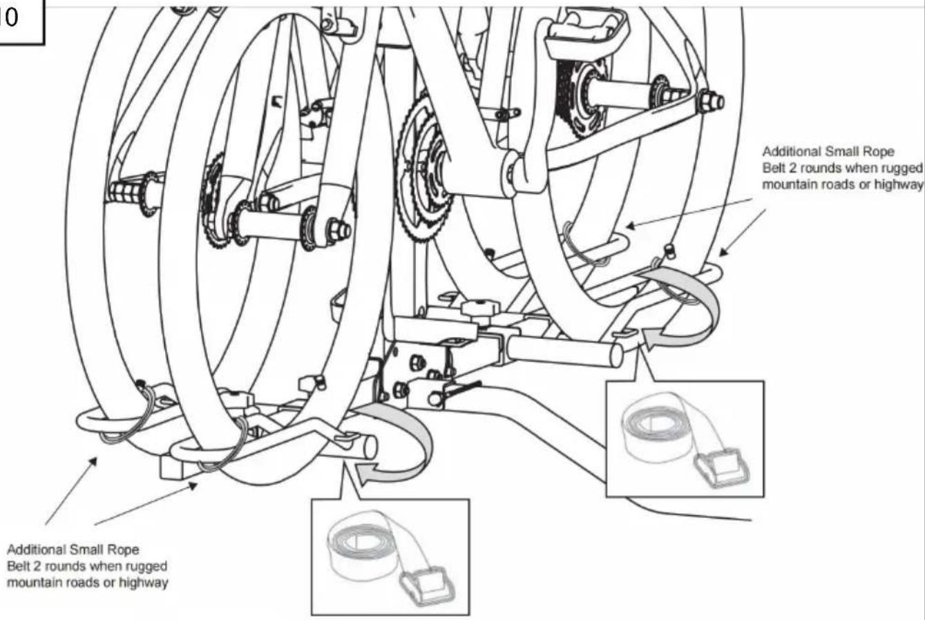
Technical line drawing of a mechanical assembly with hoses and springs, showing internal components and assembly steps (no text or symbols)Follow the method in step 8 to place the second bicycle on the frame, the locking knobs on E, F, and G. Use straps I to fix the front and re bicycle to the frame, and then use straps J to tie the crossbeams of the bicycles together.
10
11
natural_image
Technical line drawing of a vehicle suspension system with attached suspension bracket (no text or symbols)
Max
40 lbs
(18 kg
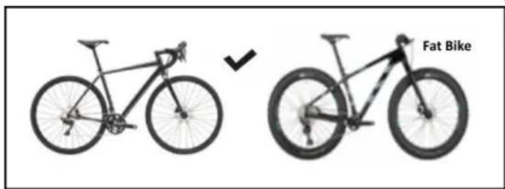
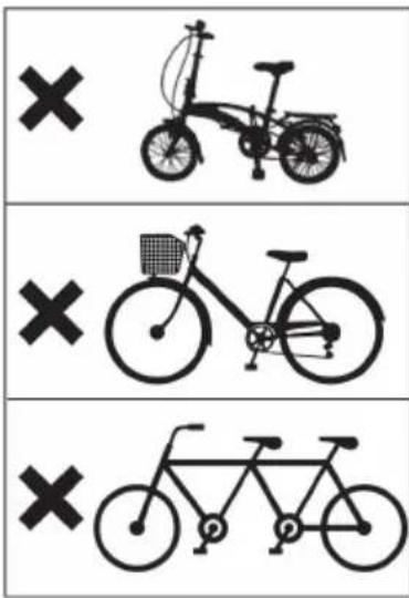
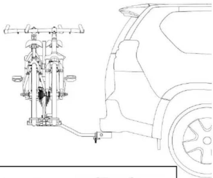
Note: Some models of bicycles cannot use this product, with a maximum capacity of 40 lbs x2!
12
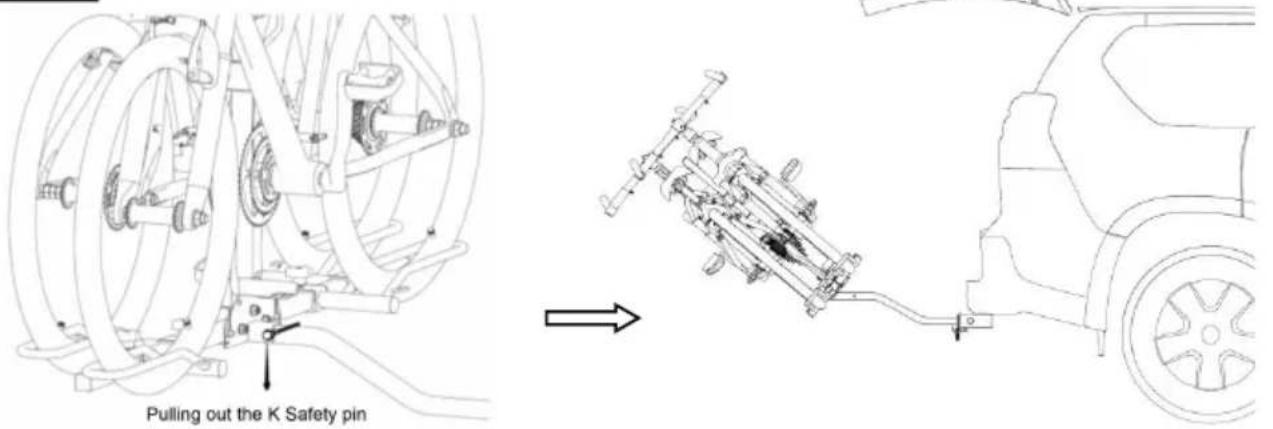
After opening the safety pin on the rack, as shown in the figure, flip the backwards to the stop, and the trunk door of the car can be opened s
13
natural_image
Technical line drawing of a car's side view showing suspension system mounted on the wheel (no text or symbols)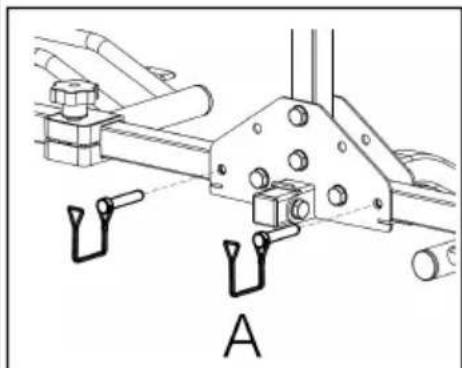
natural_image
Technical line drawing of a mechanical assembly with mounting flanges and components (no text or symbols)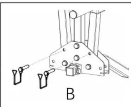
natural_image
Technical line drawing of a mechanical component with two hanging pins and a central housing (no text or symbols)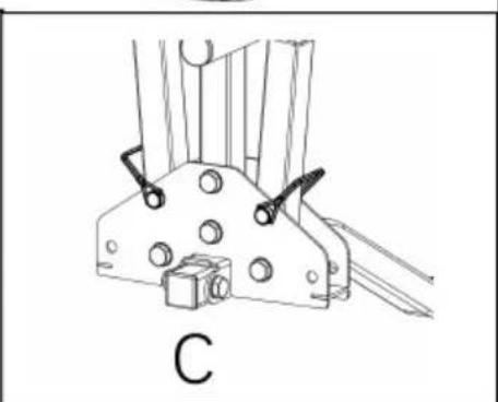
natural_image
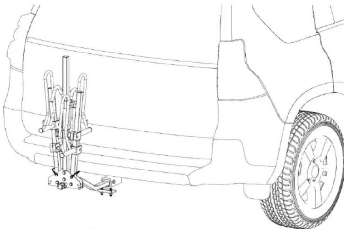
Technical line drawing of a mechanical component with mounting holes and a labeled section C (no text or symbols beyond label)When the Hitch Bike Rack is temporarily not suspended, the left and right pipes of the frame can be folded up as shown in the figure, and the method can be followed in the order of ABC.
CAUTION
- Risk of damage! Do not take the product through a car wash.
Cleaning
- When cleaning vehicles and products, use only water soluble cleaners.
- Never use corrosive detergents, wire brushes, abrasive scourers, metal or sharp utensils to clean the product.
Maintenance
- This product must always be cleaned and maintained, especially in winter.
- Screws, nuts and locks (if fitted) must be lubricated at regular intervals.
- Store the product in a cool and dry place away from children and pets, is its original packaging.
VEVOR®
TOUGH TOOLS, HALF PRICE
Technical Support and E-Warranty Certificate
www.vevor.com/support
VEVOR®
TOUGH TOOLS, HALF PRICE
natural_image
Technical illustration of two mechanical vehicle chassis components (no text or symbols)BESOIN D'AIDE? CONTACTEZ-NOUS!
PARAMÈTRES DU PRODUIT
natural_image
Exploded view diagram of a mechanical assembly with multiple components and mounting brackets (no text or labels)Outils requis :
1× Gants de protection
natural_image
Technical line drawing showing mechanical assembly steps: shafts, bracket assembly, and final assembly (no text or symbols)natural_image
Technical illustration showing a mechanical assembly before and after modification, with no visible text or symbols.natural_image
Technical line drawing of a mechanical clamp or bracket assembly (no text or symbols)natural_image
Line drawing of a car's rear suspension system with mechanical components and a side view (no text or symbols)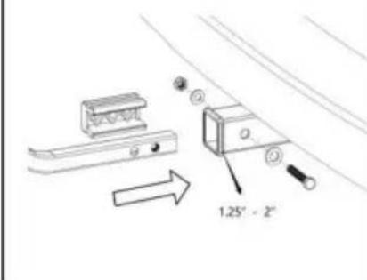
natural_image
Technical line drawing of a mechanical bracket or clamp assembly (no text or symbols)natural_image
Line drawing of a car exterior view with a mounted tire-mounted bracket and a side-mounted lift (no text or symbols)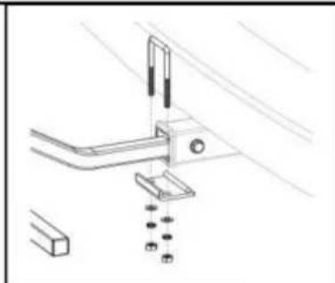
natural_image
Technical line drawing of a mechanical bracket assembly with mounting holes and a ruler (no text or symbols)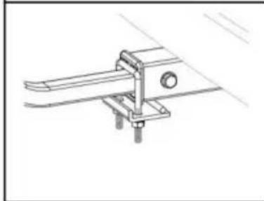
natural_image
Technical line drawing of a mechanical clamp or bracket assembly (no text or symbols)natural_image
Line drawing of a bicycle-mounted charging station next to a parked car (no text or symbols)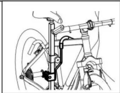
natural_image
Technical line drawing of a bicycle suspension system with no visible text or symbolsnatural_image
Technical line drawing of a mechanical assembly with hoses and components, showing assembly steps and component details (no text or symbols)natural_image
Technical line drawing of a car's side view showing suspension components and wheel assembly (no text or labels)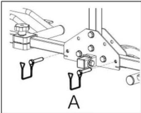
natural_image
Technical line drawing of a mechanical assembly with labeled component A (no text or symbols beyond label)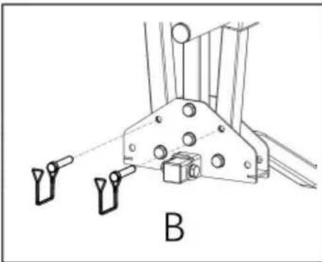
natural_image
Technical line drawing of a mechanical bracket with two hanging weights and a labeled component 'B' (no text or symbols beyond label)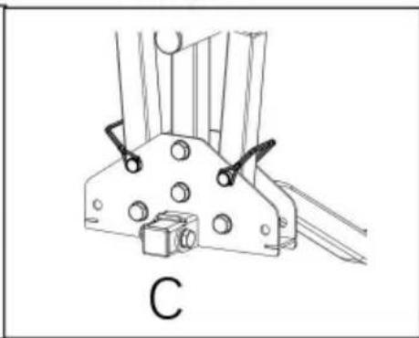
natural_image
Technical line drawing of a mechanical bracket or clamp assembly with mounting holes and a labeled component 'C' (no text or symbols beyond label)natural_image
Technical illustration of two mechanical vehicle chassis components (no text or symbols)natural_image
Exploded view diagram of a mechanical assembly with multiple components and mounting brackets (no text or labels)1 × 17 mm Schraubenschlüssel
1. Montageverfahren
1
natural_image
Technical line drawing showing mechanical assembly steps: shafts, bracket assembly, and final assembly (no text or symbols)natural_image
Technical illustration showing a mechanical assembly before and after modification, with no visible text or symbols.natural_image
Technical line drawing of a mechanical clamp or bracket assembly (no text or symbols)natural_image
Line drawing of a car's rear suspension system with tool arm and tire assembly (no text or symbols)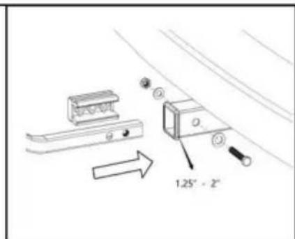
natural_image
Technical line drawing of a mechanical clamp or bracket assembly (no text or symbols)natural_image
Line drawing of a car rear view with a mounted tire-mounted bracket and a side-mounted rack (no text or symbols)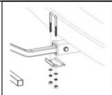
natural_image
Technical line drawing of a mechanical bracket assembly with mounting holes and a ruler (no text or symbols)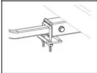
natural_image
Technical line drawing of a mechanical clamp or bracket assembly (no text or symbols)natural_image
Line drawing of a bicycle-mounted charging station next to a parked car (no text or symbols)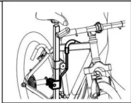
natural_image
Mechanical assembly diagram showing a hand operating a bicycle frame with levers and suspension components (no text or labels)natural_image
Technical line drawing of a mechanical assembly with hoses and components, showing assembly steps and component details (no text or symbols present)natural_image
Technical line drawing of a car's side view showing suspension components and wheel assembly (no text or labels)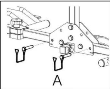
natural_image
Technical line drawing of a mechanical assembly with labeled component A (no text or symbols beyond label)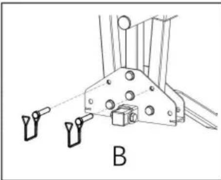
natural_image
Technical line drawing of a mechanical bracket with two hanging weights and a labeled component 'B' (no text or symbols beyond label)
natural_image
Technical line drawing of a mechanical bracket or clamp assembly with mounting holes and a labeled component 'C' (no text or symbols beyond label)natural_image
Technical illustration of two mechanical vehicle chassis components (no text or symbols)natural_image
Exploded view diagram of a mechanical assembly with multiple components and mounting brackets (no text or labels)Strumenti necessari:
natural_image
Technical line drawing showing mechanical assembly steps: shafts and housing with mounting holes (no text or symbols)natural_image
Technical illustration showing a mechanical assembly before and after modification, with no visible text or symbols.natural_image
Technical line drawing of a mechanical clamp or bracket assembly (no text or symbols)natural_image
Line drawing of a car's rear suspension system with mechanical components and a side view (no text or symbols)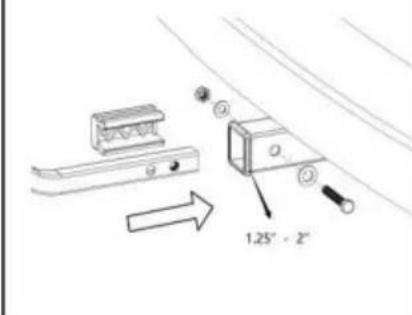
natural_image
Technical line drawing of a mechanical bracket or clamp assembly (no text or symbols)natural_image
Line drawing of a car exterior view with a mounted tire-mounted bracket and a side-mounted rack (no text or symbols)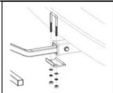
natural_image
Technical line drawing of a mechanical bracket assembly with mounting holes and a ruler (no text or symbols)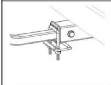
natural_image
Technical line drawing of a mechanical clamp or bracket assembly (no text or symbols)natural_image
Line drawing of a bicycle-mounted charging station next to a parked car (no text or symbols)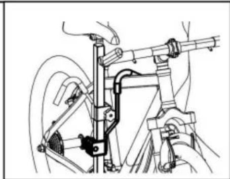
natural_image
Mechanical assembly diagram showing a bicycle frame with levers and suspension components (no text or labels)natural_image
Technical line drawing of a mechanical assembly with hoses and components, showing assembly steps and component details (no text or symbols)natural_image
Technical line drawing of a car's side view showing suspension components and wheel assembly (no text or labels)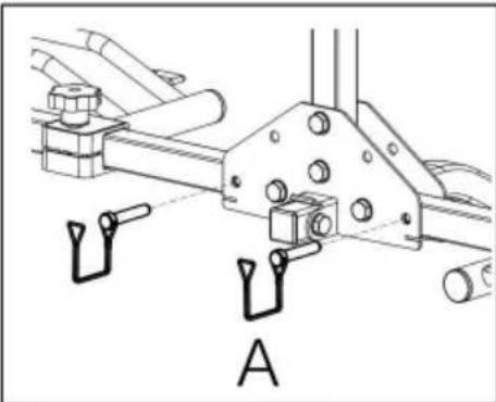
natural_image
Technical line drawing of a mechanical assembly with labeled component A (no text or symbols beyond label)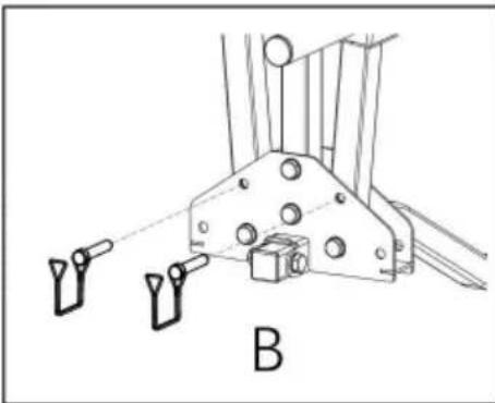
natural_image
Technical line drawing of a mechanical bracket with two hanging weights and a labeled component 'B' (no text or symbols beyond label)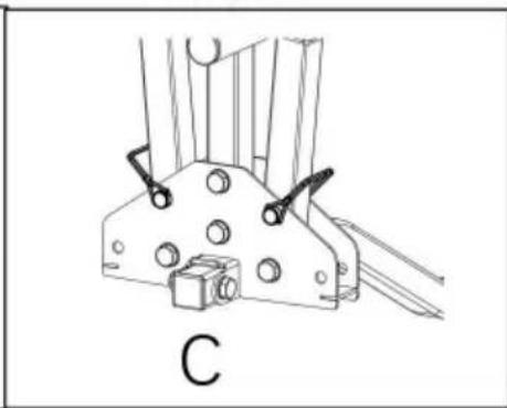
natural_image
Technical line drawing of a mechanical bracket or clamp assembly with mounting holes and a labeled component 'C' (no text or symbols beyond label)natural_image
Technical illustration of two mechanical vehicle chassis components (no text or symbols)natural_image
Exploded view diagram of a mechanical assembly with multiple components and mounting brackets (no text or labels)natural_image
Technical line drawing showing mechanical assembly steps: shafts and housing with mounting holes (no text or symbols)natural_image
Technical illustration showing a mechanical assembly before and after modification, with no visible text or symbols.natural_image
Technical line drawing of a mechanical clamp or bracket assembly (no text or symbols)natural_image
Line drawing of a car's rear suspension system with mechanical components and a side view (no text or symbols)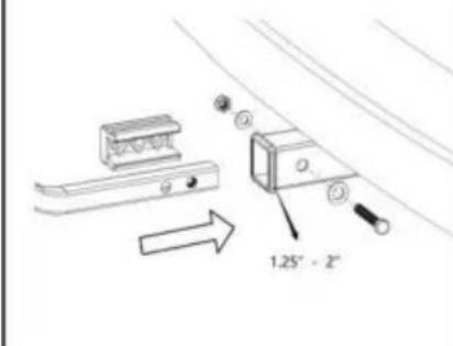
natural_image
Technical line drawing of a mechanical bracket or clamp assembly (no text or symbols)natural_image
Line drawing of a car exterior view with a mounted tire-mounted rack and a side-mounted lift (no text or symbols)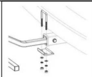
natural_image
Technical line drawing of a mechanical assembly with no visible text or symbols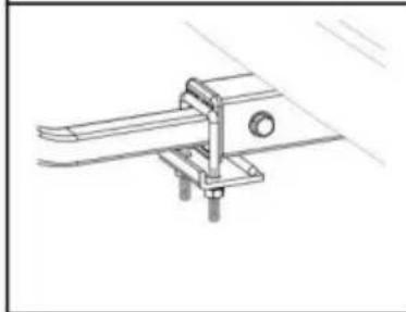
natural_image
Technical line drawing of a mechanical clamp or bracket assembly (no text or symbols)natural_image
Line drawing of a bicycle-mounted charging station next to a parked car (no text or symbols)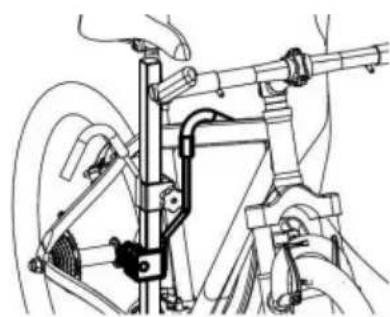
natural_image
Technical line drawing of a bicycle frame assembly with no visible text or symbolsnatural_image
Technical line drawing of a mechanical assembly with hoses and components, showing assembly steps (no text or symbols)natural_image
Technical line drawing of a car's side view showing suspension components and wheel assembly (no text or labels)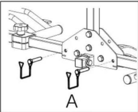
natural_image
Technical line drawing of a mechanical assembly with labeled component A (no text or symbols beyond label)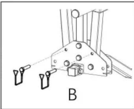
natural_image
Technical line drawing of a mechanical bracket with two hanging weights and a labeled component 'B' (no text or symbols beyond label)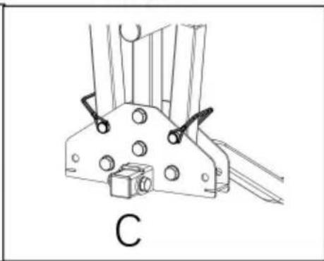
natural_image
Technical line drawing of a mechanical bracket or clamp assembly with mounting holes and a labeled component 'C' (no text or symbols beyond label)natural_image
Technical illustration of two mechanical vehicle chassis components (no text or symbols visible)POTRZEBUJESZ POMOCY? SKONTAKTUJ SIĘ Z NAMI!
natural_image
Exploded view diagram of a mechanical assembly with multiple components and mounting brackets (no text or labels)Wymagane narzędzia:
1× Rękawice ochronne
natural_image
Technical illustration of mechanical assembly steps showing shafts and housing components (no text or symbols)natural_image
Technical illustration showing a mechanical assembly before and after modification, with no visible text or symbols.natural_image
Technical line drawing of a mechanical clamp or bracket assembly (no text or symbols)natural_image
Line drawing of a car's rear suspension system with mechanical components and a side view (no text or symbols)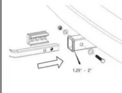
natural_image
Technical line drawing of a mechanical bracket or clamp assembly (no text or symbols)natural_image
Line drawing of a car exterior view with a mounted tire-mounted bracket and a side-mounted rack (no text or symbols)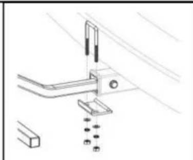
natural_image
Technical line drawing of a mechanical bracket assembly with mounting holes and a ruler (no text or symbols)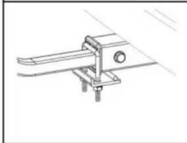
natural_image
Technical line drawing of a mechanical clamp or bracket assembly (no text or symbols)natural_image
Line drawing of a bicycle-mounted charging station next to a parked car (no text or symbols)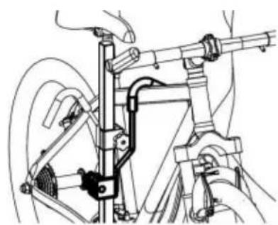
natural_image
Mechanical assembly diagram showing a hand operating a lever mechanism with no visible text or symbolsnatural_image
Technical line drawing of a mechanical assembly with hoses and components, showing assembly steps and component details (no text or symbols)natural_image
Technical line drawing of a car's side view showing suspension components and wheel assembly (no text or labels)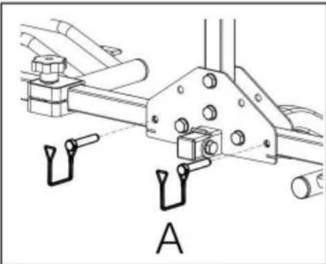
natural_image
Technical line drawing of a mechanical assembly with labeled component A (no text or symbols beyond label)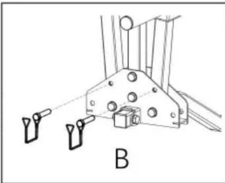
natural_image
Technical line drawing of a mechanical bracket with two hanging weights and a labeled component 'B' (no text or symbols beyond label)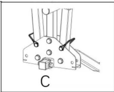
natural_image
Technical line drawing of a mechanical bracket or clamp assembly with mounting holes and a labeled component 'C' (no text or symbols beyond label)natural_image
Technical illustration of two mechanical vehicle chassis components (no text or symbols)HULP NODIG? NEEM CONTACT MET ONS OP!
natural_image
Exploded view diagram of a mechanical assembly with multiple components and mounting brackets (no text or labels)natural_image
Technical line drawing showing mechanical assembly steps: shafts, bracket assembly, and final assembly (no text or symbols)natural_image
Technical illustration showing a mechanical assembly before and after modification, with no visible text or symbols.natural_image
Technical line drawing of a mechanical clamp or bracket assembly (no text or symbols)natural_image
Line drawing of a car's rear suspension system with tool lift and tire assembly (no text or symbols)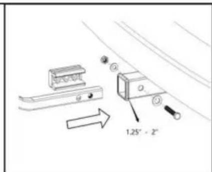
natural_image
Technical line drawing of a mechanical clamp or bracket assembly (no text or symbols)natural_image
Line drawing of a car rear view with a mounted tire-mounted bracket and suspension system (no text or symbols)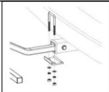
natural_image
Technical line drawing of a mechanical bracket assembly with mounting holes and a ruler (no text or symbols)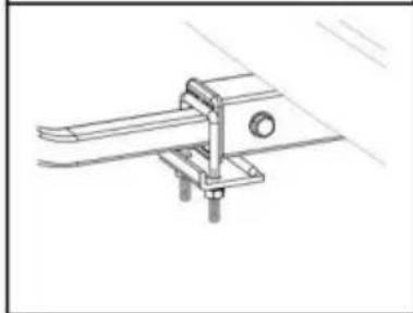
natural_image
Technical line drawing of a mechanical clamp or bracket assembly (no text or symbols)natural_image
Line drawing of a bicycle-mounted charging station next to a parked car (no text or symbols)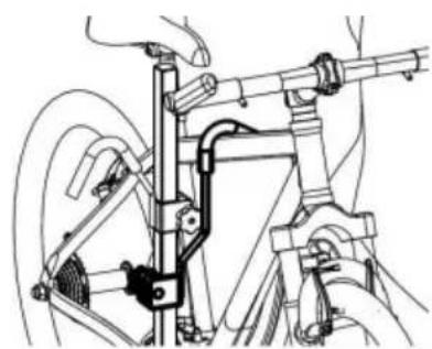
natural_image
Technical line drawing of a bicycle suspension system with hand and wheel assembly (no text or labels)natural_image
Technical line drawing of a mechanical assembly with hoses and components, showing assembly steps and component details (no text or symbols)natural_image
Technical line drawing of a car's side view showing suspension components and wheel assembly (no text or labels)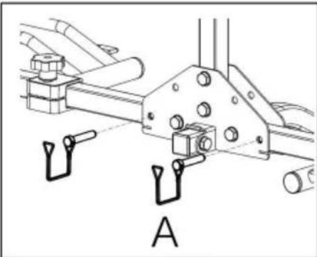
natural_image
Technical line drawing of a mechanical assembly with labeled component A (no text or symbols beyond label)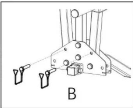
natural_image
Technical line drawing of a mechanical bracket with two hanging weights and a labeled component 'B' (no text or symbols beyond label)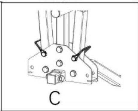
natural_image
Technical line drawing of a mechanical bracket or clamp assembly with mounting holes and a labeled component 'C' (no text or symbols beyond label)natural_image
Technical illustration of two mechanical vehicle chassis components (no text or symbols visible)BEHÖVER HJÄLP? KONTAKTA OSS!
natural_image
Exploded view diagram of a mechanical assembly with multiple components and mounting brackets (no text or labels)Nödvändiga verktyg:
1× Skyddshandskar
natural_image
Technical line drawing showing mechanical assembly steps: shafts, bracket assembly, and final assembly (no text or symbols)natural_image
Technical illustration showing a mechanical assembly before and after modification, with no visible text or symbols.natural_image
Technical line drawing of a mechanical clamp or bracket assembly (no text or symbols)natural_image
Line drawing of a car's rear suspension system with mechanical components and a side view (no text or symbols)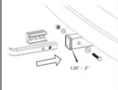
natural_image
Technical line drawing of a mechanical bracket or clamp assembly (no text or symbols)natural_image
Line drawing of a car exterior view with a mounted tire-mounted rack and a side-mounted lift (no text or symbols)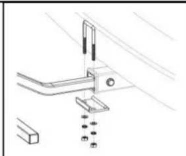
natural_image
Technical line drawing of a mechanical assembly with no visible text or symbols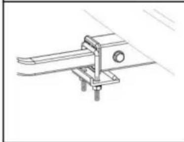
natural_image
Technical line drawing of a mechanical clamp or bracket assembly (no text or symbols)natural_image
Line drawing of a bicycle-mounted charging station next to a parked car (no text or symbols)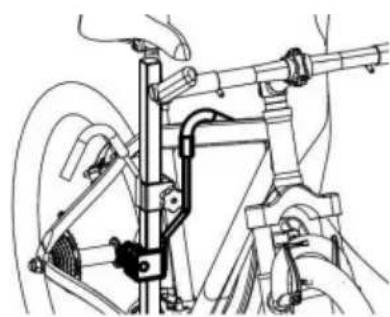
natural_image
Technical line drawing of a bicycle frame assembly with no visible text or symbolsnatural_image
Technical line drawing of a mechanical assembly with hoses and components, showing assembly steps (no text or symbols)natural_image
Technical line drawing of a car's side view showing suspension components and wheel assembly (no text or labels)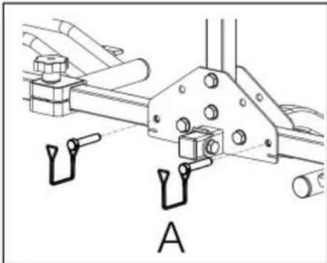
natural_image
Technical line drawing of a mechanical assembly with mounting flanges and a labeled component 'A' (no text or symbols beyond label)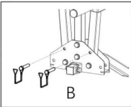
natural_image
Technical line drawing of a mechanical assembly with two hanging components and a labeled section B (no text or symbols beyond label)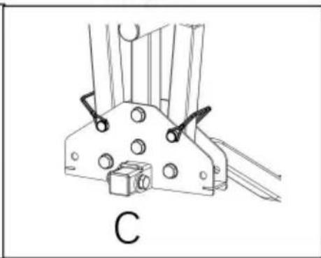
natural_image
Technical line drawing of a mechanical bracket or clamp assembly with mounting holes and a labeled component 'C' (no text or symbols beyond label)www.vevor.com/support
- HITCH BIKE RACK
- VEVOR®
- NEED HELP? CONTACT US!
- PACKING LIST
- DANGER
- Risk of accidents!
- WARNING
- Risk of damage!
- Road Safety
- CAUTION
- Product Safety
- NOTICE
- Inspection
- Before First Use
- Required tools:
- Assembly Procedures
- Installation Procedures
- Cleaning
- Maintenance
- TOUGH TOOLS, HALF PRICE
- BESOIN D'AIDE? CONTACTEZ-NOUS!
- Outils requis :
- Montageverfahren
- Strumenti necessari:
- HULP NODIG? NEEM CONTACT MET ONS OP!
- BEHÖVER HJÄLP? KONTAKTA OSS!
- Nödvändiga verktyg:
Brand : Vevor
Model : RC-1803J
Category : Bike rack