
SS24005 - Bicycles Vevor - Free user manual and instructions
Find the device manual for free SS24005 Vevor in PDF.
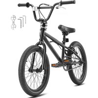


| Product type | BMX Bike |
| Brand | Vevor |
| Model | SS24005 (series SS24001-SS24005) |
| Assembly | Required (by an adult) |
| Recommended age | From 3 years with adult supervision |
| Brakes | Front and rear hand brakes (caliper) + coaster brake |
| Braking system | Brake cables with gyroscopic guide (depending on model) |
| Handlebar | Handlebar with adjustable stem (threaded or threadless type) |
| Wheels | 20-inch wheels (estimated) |
| Tires | Tires with inner tube, max pressure indicated on sidewall |
| Chain | Roller chain, tension adjustable by moving rear wheel |
| Pedals | Right (R) and left (L) pedals with opposite threads |
| Seat | Height-adjustable seat with seat post and clamp (quick release or bolt) |
| Reflectors | Front (white) and rear (red) reflector included |
| Accessories | Kickstand, bell (depending on model) |
| Chain guard | Present (chain guard) |
| Pegs | Possibility to install threaded pegs (optional) |
| Safety | Helmet mandatory, obey traffic laws |
| Maintenance | Chain lubrication (20W oil), check brakes and tire pressure |
| Support | www.vevor.com/support |
| Repairability | Spare parts available via Vevor |
Frequently Asked Questions - SS24005 Vevor
User questions about SS24005 Vevor
0 question about this device. Answer the ones you know or ask your own.
Ask a new question about this device
Download the instructions for your Bicycles in PDF format for free! Find your manual SS24005 - Vevor and take your electronic device back in hand. On this page are published all the documents necessary for the use of your device. SS24005 by Vevor.
USER MANUAL SS24005 Vevor
Technical Support and E-Warranty Certificate www.vevor.com/support
BMX Bike
MODEL: SS24001; SS24002; SS24003; SS24004; SS24005
We continue to be committed to providing you with tools at competitive prices. "Save Half", "Half Price", or any other similar expressions used by us only represent an estimate of savings you might benefit from buying certain tools with us compared to the major top brands and do not necessarily mean to cover all categories of tools offered by us. You are kindly reminded to verify carefully when placing an order with us if you are actually saving half in comparison with the top major brands.
MODEL: SS24001; SS24002; SS24003; SS24004; SS24005
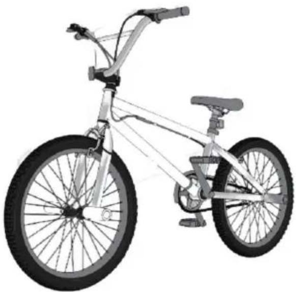
Note: The product picture is for reference; the actual details shall prevail.
NEED HELP? CONTACT US!
Have product questions? Need technical support? Please feel free to contact us:
Technical Support and E-Warranty Certificate www.vevor.com/support
This is the original instruction. Please read all manual instructions carefully before operating. VEVOR reserves a clear interpretation of the user manual. The appearance of the product shall be subject to the product you received. Please forgive us that we won't inform you again if there are any technology or software updates on our product.
Thank you very much for choosing this product.
Please read all of the instructions before using it. The information will help you achieve the best possible results.
Operation safety
Meanings of Warnings:
This symbol is important. See the word
"CAUTION" or "WARNING" which follows it.
The word "CAUTION" is before mechanical instructions. If you do not obey these instructions, mechanical damage or failure of a part of the bicycle can occur.
The word "WARNING" is before personal safety instructions. If you do not obey these instructions, injury to the rider or to others can occur.
CHOKING HAZARD. Small Parts. Not for children under 3 years. Adult assembly is required.
Continuous adult supervision is required.
Do not add a motor to the product.
Do not tow or push the product.
Do not modify the product.
Replace worn or broken parts immediately with original equipment. If anything does not operate properly, discontinue use.
WARNING - FREEWHEEL (RIM) BRAKES:
Some models do NOT have a foot (pedal) brake.
Ensure your child understands and can operate the hand
brakes.
Always use both hand brakes when stopping the bike.
When stopping, apply front and rear brakes evenly. An unstable condition can occur if the front brake is used too hard, resulting in injury to the rider or others.
WARNING:
This bicycle is made to be ridden by one rider at a time for general transportation and recreational use. It is not made to withstand the abuse of stunting and jumping.
If the bicycle was purchased unassembled, it is the owner's responsibility to follow all assembly and adjustment instructions exactly as written in this manual, and any "Special Instructions" supplied, and to make sure all fasteners and components are securely tightened.
NOTE: Periodically check that all fasteners and components are securely tightened. If the bicycle was purchased assembled, it is the owner's responsibility, before riding the bicycle for the first time, to make sure the bicycle has been assembled and adjusted exactly as written in this manual, and any "Special Instructions" supplied, and to make sure all fasteners and components are securely tightened.
NOTE: If the product is assembled, please proceed to the following sections:
Testing Seat Clamp and Post Clamp Tightness.
Testing Stem and Handlebar Tightness.

WARNING:
CHOKING HAZARD - small parts.
Not for children under 3 years.

Rules of the Road
WARNING: Failure of the rider to obey the following "Rules of the Road" can result in injury to the rider or to others.
- Obey all traffic regulations, signs, and signals. Always wear a bicycle helmet that meets safety standards, as well as local safety standards.
- Ride on the correct side of the road, in a single file, and in a straight line.
- If possible, avoid riding at night, dusk, dawn, and any other time of poor visibility.
- If you must ride at night or at times of poor visibility: ● Purchase, install, and use a headlight and taillight.
- All states require headlights for nighttime riding, and taillights are required in some states.
- Battery-powered lights or flashing safety lights are also recommended.
Reflectors: For your own safety, do not ride the bicycle if the reflectors are incorrectly installed, damaged, or missing. Make sure the front and rear reflectors are vertical. Do not allow the visibility of the reflectors to be blocked by clothing or other articles. Dirty reflectors do not work well. Clean the reflectors, as necessary, with soap and a damp cloth. Make yourself more visible to motorists.
- Wear light-colored or reflective clothing, such as a reflective vest and reflective bands for your arms and legs.
- Use reflective tape on your helmet.
- Do not let anything cover the reflectors.
Use extra caution in wet weather:
Ride slowly on damp surfaces because the tires will slide more easily.
Allow increased braking distance in wet weather.
Avoid these hazards to prevent loss of control or damage to your wheels:
Be aware of drain grates, soft road edges, gravel or sand, potholes or ruts, wet leaves, or paving.
Cross railroad tracks at a right angle to prevent the loss of control. Avoid unsafe actions while riding.
- Do not carry any passengers.
- Do not carry any items or attach anything to your bicycle that could hinder your vision, hearing, or control.
Always maintain focus and attention while riding. This means no riding with both hands off the handlebar. By doing so, you're ensuring that you're fully in control of your bicycle and ready to respond to any situation that may arise.
- Do not add a motor to the product.
- Do not tow or push the product.
- Do not modify the product.
Replace worn or broken parts immediately with original equipment. If anything does not operate properly, discontinue use.
NOTE: Bikes under 20" are not intended for use on roads.
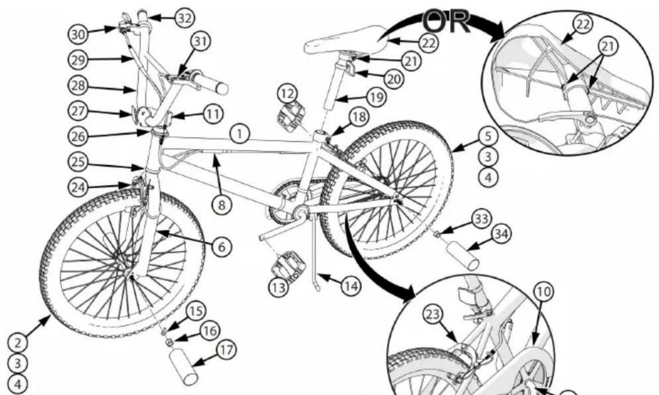
Part Assembly View & List

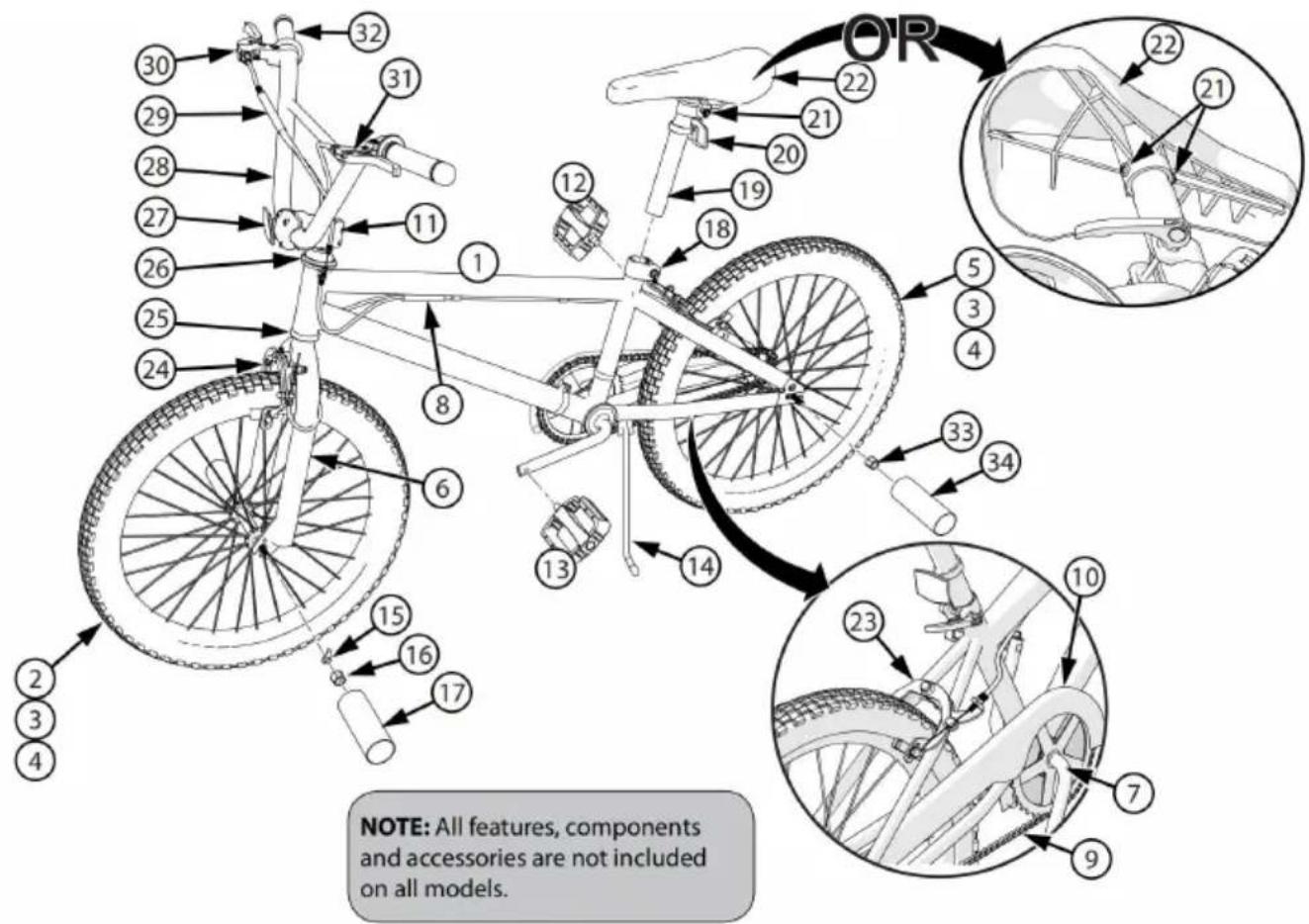
| NO. | Description | NO. | Description |
| 1 | Frame | 19 | Seat Post |
| 2 | Front Wheel Assembly | 20 | Rear Reflector |
| 3 | Tire(x2) | 21 | Seat Post Hardware |
| 4 | Tube(x2) | 22 | Seat |
| 5 | Rear Wheel Assembly | 23 | Rear Brake |
| 6 | Fork | 24 | Front Brake |
| 7 | Crank and Spindle Set | 25 | Head Set Bearings |
| 8 | Lower Brake Cable Coupler (various models) | 26 | Gyro Head Set |
| 9 | Chain | 27 | Front Reflector |
| 10 | Chain Guard | 28 | Handlebars |
| 11 | Handlebar Stem | 29 | Upper Brake Cable Coupler (various models) |
| 12 | Right Pedal | 30 | Right Brake Lever |
| 13 | Left Pedal | 31 | Left Brake Lever |
| 14 | Kick Stand | 32 | Grips (x2) |
| 15 | Wheel Retainer(x2) | 33 | Rear Axle Nut(x2) |
| 16 | Front Axle Nut (x2) | 34 | Rear Pegs (various models) |
| 17 | Front Pegs (various models) | 35 | Bell(not shown-if equipped) |
| 18 | Seat Post Clamp |
Introduction to Assembly
This manual has been made for several different bikes:
Some illustrations may vary slightly from the actual product.
Follow instructions completely.
If the bicycle has parts not described in this manual, look for separate "Special Instructions" supplied with the bike. Models may have different accessories such as bags, baskets, reflectors, cup holders, etc.
Not all features, components, and accessories are included in all models. Use the Index page to locate specific sections of this manual. Please read through this entire manual before beginning assembly or maintenance. If you are not confident with assembling this unit, it is highly recommended to refer to a local bike shop. Your safety and the proper functioning of the bicycle are of utmost importance.
WARNING:
Keep small parts away from children during assembly.
NOTE: All of the directions (right, left, front, rear, etc.) in this
manual are as seen by the rider while seated on the bicycle.
Do not dispose of the carton and packaging until you complete the assembly of the bicycle.
This can prevent accidentally discarding parts of the bicycle.
Tools Needed (not included)
Small Adjustable Wrench
(Jaws must open at least 9/16 inch.)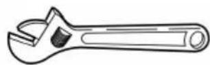
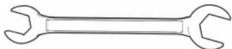
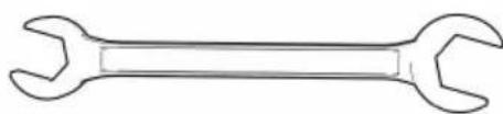
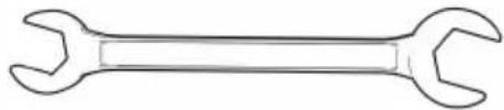
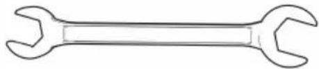
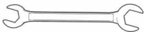
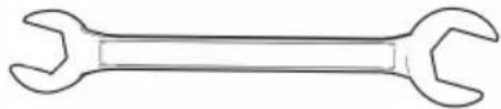
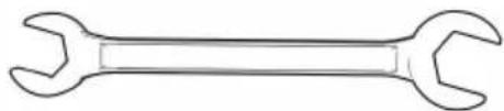
Open-end Wrenches
Flat-blade Screwdriver

Phillips Screwdriver
Slip-Joint Pliers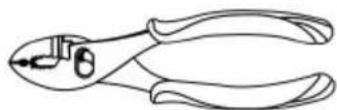
Metric Allen Wrenches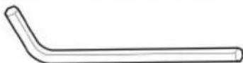
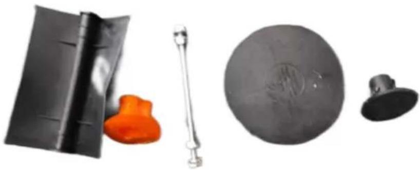
Packing material protection accessories
NOTE: These packaging protective accessories are disposable and they are not used to assemble products
Step 1:
Installing the Front Wheel
NOTE: See Brake Section to loosen and Re-attach front Brakes (if equipped)
If the Axle Nuts (A) are already attached to the front wheel axle, re-tighten them with an open-end or adjustable wrench.
Set the wheel into the front fork (B). Install wheel retainers (C) making sure the tabs are in the fork (D) tab holes. Attach the front wheel with the Nuts. Put the wheel in the center of the fork and tighten the Axle Nuts securely. Always refer to the torque table for the recommended torque guides you in achieving the correct torque for the Axle Nuts.
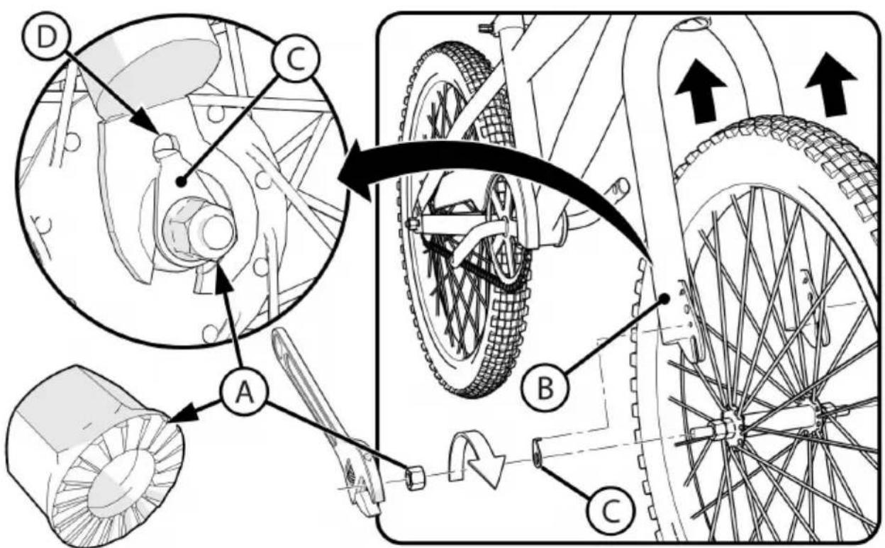
NOTE: Ensure wheel spins freely without contacting fork or fender. WARNING: Do not use Nuts without serrations to attach the front wheel. WARNING: Failure to obey these steps can allow the front wheel to detach while riding. This can cause injury to the rider or to others.
Step 2:
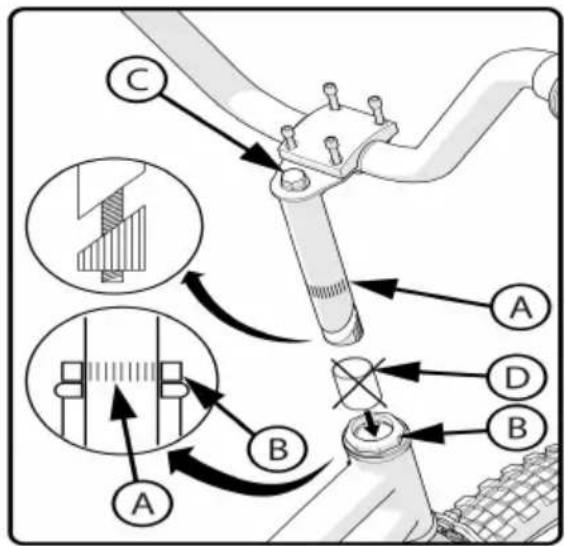
Handlebar and Stem Installation - No Gyro Brake
NOTE: Check which Stem style your bike has and use one of the following installation
guides.
WARNING: To prevent steering system damage and possible loss of control, the "MIN-|N" (minimum insertion) mark (A) on the Stem must be below the top of the lock nut (B)
QUILL TYPE STEM:
NOTE: Remove plastic Cap (D) from the end of the Stem.
- Insert the Stem into the fork.
- Point the Stem towards the front of the bike.
a. With the Stem aligned with the front tire, securely tighten the Bolt (C). See the Torque Chart for recommended torque. b. Proceed to the Handlebar installation on the next page.
THREADLESS TYPE STEMS:
NOTE: Threadless stems are preinstalled.
Proceed to the Handlebar installation on the next page.
WARNINGS:
Do not over-tighten the stem bolt (C). Over-tightening the stem can damage the steering system and cause a loss of control. Be cautious and attentive during the installation process.
Step 3:
Handlebar Installation - continued
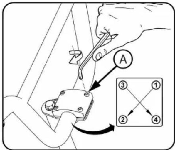
Four Bolt Clamp Top Mount: Adjust the Handlebar into a comfortable position. Tighten Clamp Screws evenly according to pattern.
NOTE: Do not over-tighten. See the Torque chart for recommended torque.
Four Bolt Clamp, Front Mount: 1. Adjust the Handlebar into a comfortable riding position. Tighten Clamp Screws (A). Check tightness of side Stem Bolts (B).
NOTE: Do not over-tighten. See Torque chart for recommended torque.
![graph TD A["A"] --> B["B"] B --> C["C"] style A fill:#f9f,stroke:#333 style B fill:#ccf,stroke:#333 style C fill:#cfc,stroke:#333 subgraph Component 1 direction LR ① --> ② ② --> ③ ③ --> ④ end subgraph Component 2 direction LR ① --> ② ② --> ④ end subgraph Component 3 direction LR ① --> ② ② --> ④ end](/content/2026/04/734251/images/17858fec3f1eb8375db1703f7e83b52c0b6f1fce4207a9789bc49a06178f34c8.jpg)
Two Bolt Stem:
- Adjust the Handlebar into a comfortable riding position. Tighten Clamp Screws (A).
NOTE: Do not over-tighten. See Torque Chart for recommended torque.
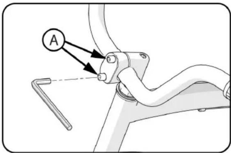
WARNING: If the Handlebar Clamp is not tight enough, the handlebar may slip in the stem. This can cause damage to the handlebar or stem, and cause loss of control.
Step 4:
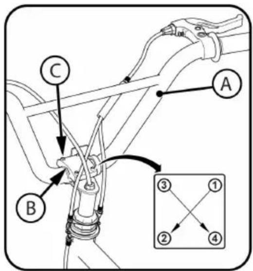
Stem and Handlebar Setup - Gyro Brake
Note: The Handlebar Stem Clamp may be preinstalled from the factory. Carefully unpack the Handlebar (A) and check for damages.
Install the Handlebar into the Clamp and secure with Clamp Screws (C).
Rotate the Handlebar into a comfortable riding position.
Tighten Clamp Screws (G) securely. See the Torque Chart for recommended torque.
Step 5:
Gyro Stem and Brake Setup
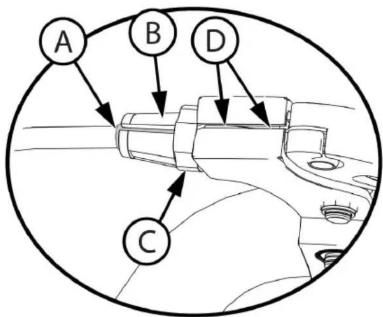
Make sure Rear Brake Cable Sheath (A) is fully inserted into the adjustment Housing at the Caliper and Hand Lever (B).
Ensure Housing Nut and Housing (B, C) are adjusted all the way in towards the Hand Lever.
Rotate Housing (B) Groove away from Cable Groove (D) and tighten Housing Nut (C).
Step 6:
Gyro Stem and Brake Setup - continued
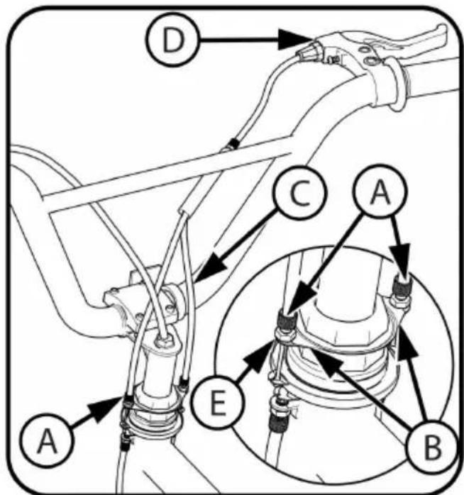
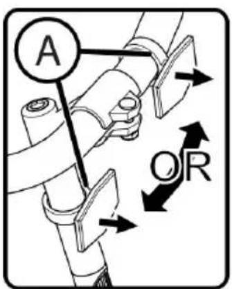
Install the two Cable Adjusters into the Gyro Plate (B) making sure that Shorter Cable (C) is on the same side as the Brake Levers (D).
Turn the Cable Adjusters and Nuts (E) all the way into the Gyro hand tight.
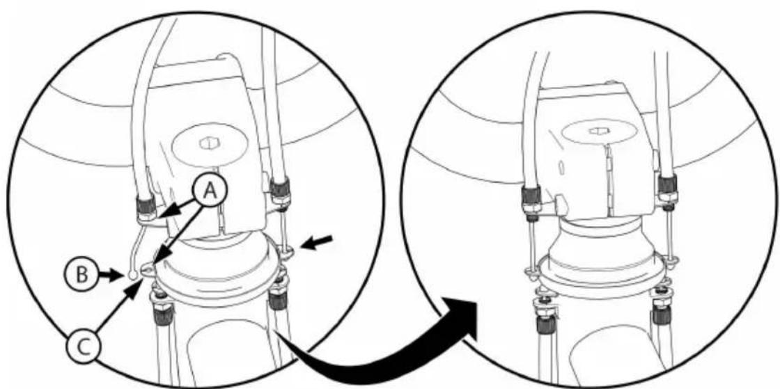
Squeeze the two sides of the Gyro Plate Slot (C) together and insert the Cable End (B) into the slot. Repeat for other sides of the Gyro Plates (A).
Gyro Brake Setup - Front Brake Cable Install
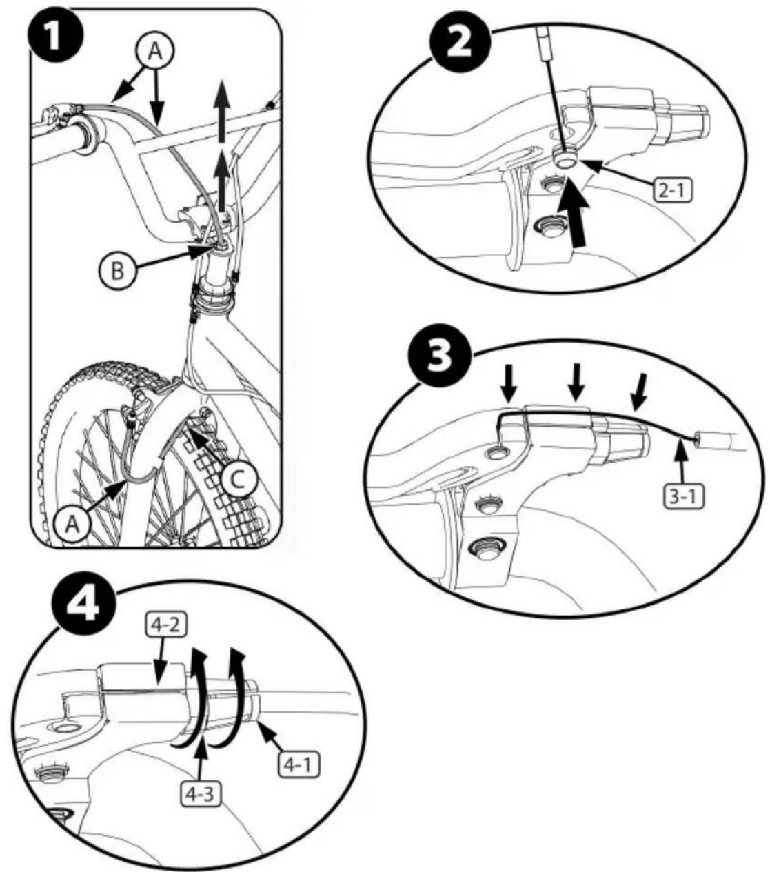
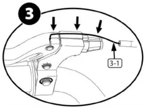
- Pull the Front Brake Cable (A) up through the Stem Nut (B) so that it is routed as shown.
- Ensure the Brake Cable does not touch the Tire (C).
- Insert Cable Barrel (2-1) into Brake Lever.
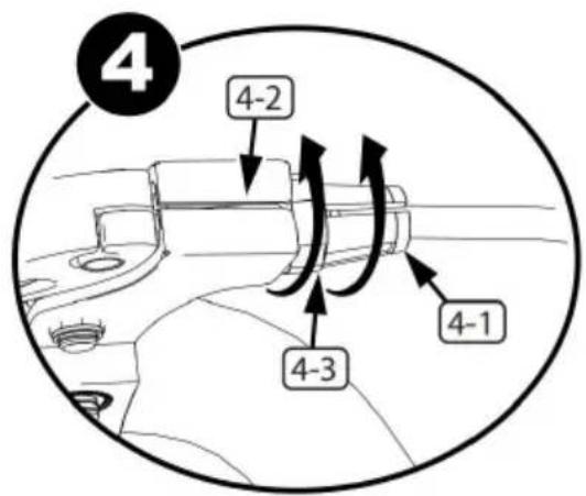
- Insert Brake Cable (3-1) into Groove as shown. Ensure Housing Nut and Housing (4-3, 4-1) are adjusted all the way in towards the Hand Lever.
- Rotate Housing (4-1) Groove away from Cable Groove (4-2) and tighten Housing Nut (4-3).
Step 7:
Gyro Brake Setup - Front Brake Cable install - continued
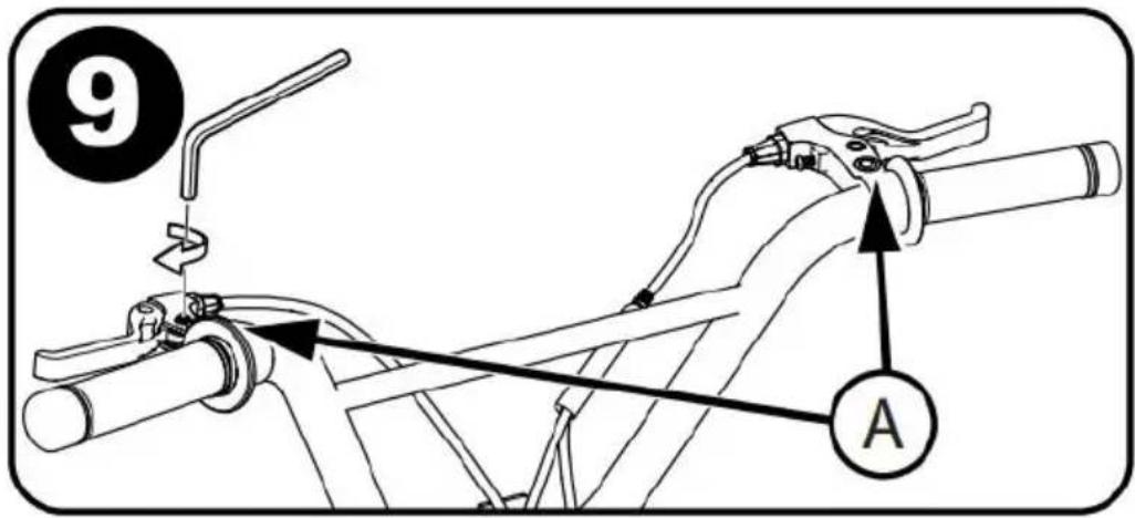
Rotate Brake Levers (A) into a comfortable riding position and tighten securely.
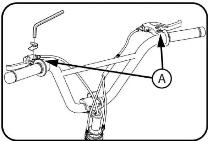
Step 8:
Testing Stem and Handlebar Tightness
To test the tightness of the stem:
Straddle the front wheel between your legs. Try to turn the front wheel by turning the handlebar. If the handlebar and stem turn without turning the front wheel, realign the stem with the wheel and tighten the stem both tighter than before (about 1/2 revolution only at a time).
Repeat this test until the handlebar and stem do not turn without turning the front wheel. This thorough approach ensures the stem is securely tightened.
To test the tightness of the handlebar clamp:
Hold the bicycle stationary and try to move the ends of the handlebar forward and backward.
CAUTION: Do not exceed 100 lbs (45 kg) push force.
If the handlebar moves, loosen the bolt(s) of the handlebar clamp.

Step 9:
Seat Installation
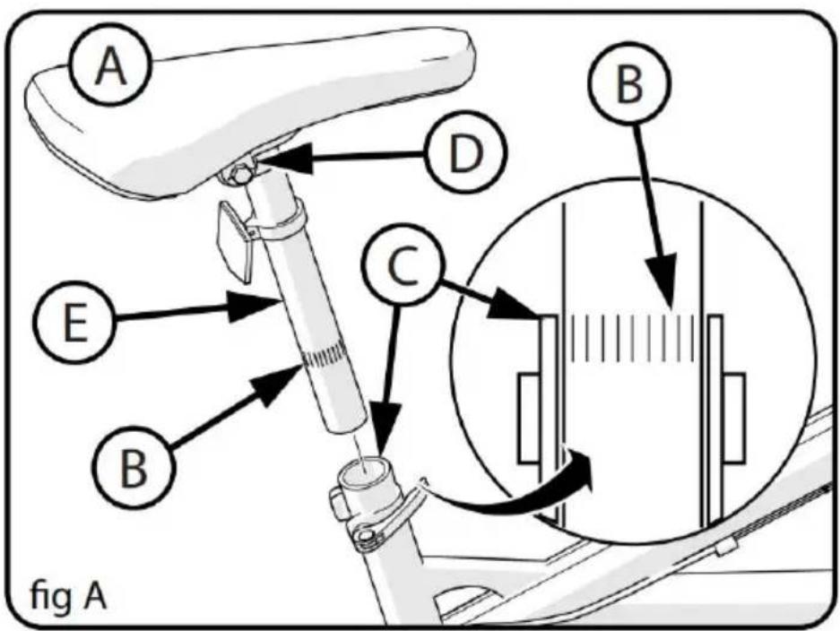
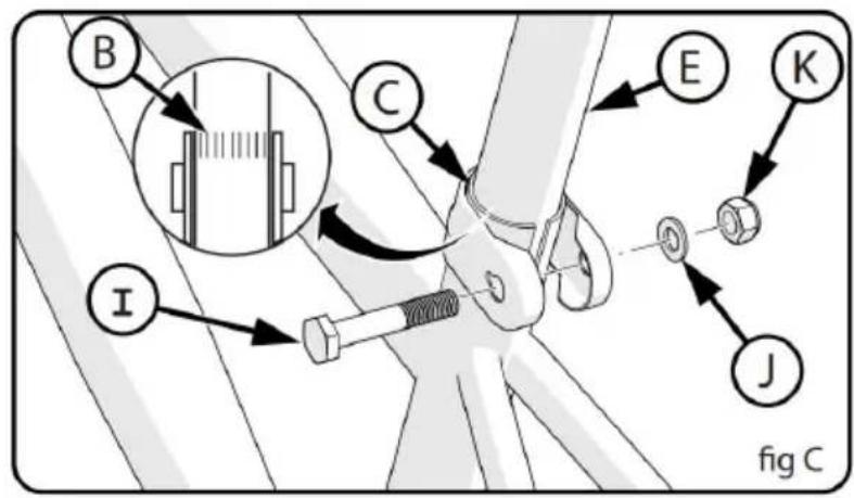
WARNING: To prevent the Seat (A) coming loose and possible loss of control, the "MIN-IN" (minimum insertion) mark (B) on the Seat Post must be below the top of the Seat Tube (C).
SEAT AND SEAT POST SETUP:
- If needed, loosen Nuts on Seat Clamp (D) and rotate Seat into position.
- Ensure the Seat Post (E) is fully through the TOP Seat Clamp (D).
- Tighten the Seat Clamp so the Seat does not move on the seat post.
- If the Seat Clamp has a Nut on each side, tighten both nuts equally.
- Point the Seat forward and put the Seat Post (E) into the Seat Tube and proceed to next step.
TIGHTEN THE QUICK RELEASE LEVER: NOTE: The words "open" and "close" are on opposite sides of the quick release lever.
CAUTION: Operate the Quick Release Lever (F) by hand only. Do not use a hammer or any other tool to tighten the quick release lever.
- Move the Quick Release Lever (F) to the "open" position so the word "open" is pointing away from the Seat Post Clamp (G).
WARNING: It would help if you used muscular force to move the quick-release lever to the "close" position. The clamping force is too light if you quickly move the lever to the "close" position. If the clamping force of the Quick Release Lever is too light, the seat post can loosen while riding. This can cause injury to the rider or others.
2. Open and close the Quick Release Lever with one hand while you turn the Adjusting Nut with the other hand.
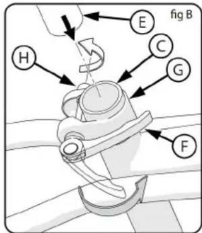
- Tighten or loosen the adjusting nut by hand, so that you first feel resistance to the quick release lever when it is perpendicular to the bicycle frame. 4. Push the Quick Release Lever to the "close" position.
- When in the "close" position, make sure the Quick Release Lever is against the Seat Post Clamp (G).
- The tightening torque of the Quick Release Lever should be tight enough so that the seat does not move during normal operation.
Seat Bolt Mount (various models)
- Some models have a Bolt (I), Washer (J) and Nut (K) instead of a Release Lever.
- If needed, loosen the nut enough to insert the Seat Post (E).
- Point the seat forward and insert Seat Post to the Minimum insert marks (B). ● Tighten Nut securely so it supports the rider without moving.
STEP: 10
Testing Seat Clamp and Post Clamp Tightness To test the tightness of the seat clamp and the post clamp, try to turn the seat side-to-side and to move the front of the seat down.
If the seat moves in the Seat Clamp:
- Loosen the Seat Clamp Nut.
Put the seat in the correct position and tighten the Seat Clamp tighter than before.
- Do this test again, until the seat does not move in the Seat Clamp. If the Seat Post moves in the Seat Tube Clamp:
- Loosen the Seat Clamp Lever. Put the Seat Post in the correct position and tighten the Seat Clamp Nut tighter than before. If necessary, tighten or loosen the Hand Nut so that the Quick Release tightens securely.
- Repeat this test until the Seat Post does not move in the Seat Clamp.
STEP: 11
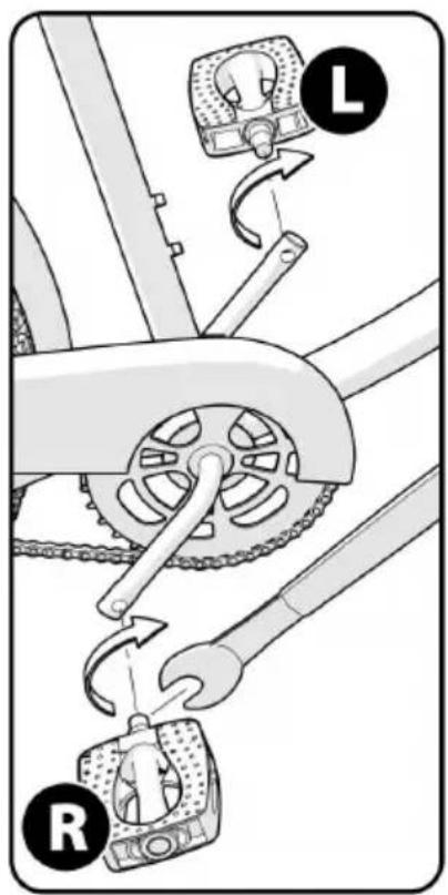
Pedal Installation
CAUTION: There is a RIGHT pedal marked (R) and a LEFT pedal marked (L).
NOTE: A Pedal Wrench is preferred for attaching Pedals. A thin open wrench can also be used.
The pedal marked (R) has right-hand threads. Tighten it in a clockwise direction. The pedal marked (L) has left-hand threads.
Tighten it in a counterclockwise direction (anti-clockwise).
Turn the right pedal marked (R) into the right side of the crank arm and the left pedal marked (L) into the left side of the crank arm.
Tighten the pedals: Make sure the threads of each pedal are fully into the crank arm.
WARNING: Ensure pedals are secure in crank arms so they do not loosen. Periodically check tightness.
STEP: 12
Reflector Installation (as equipped)
Reflector installation:
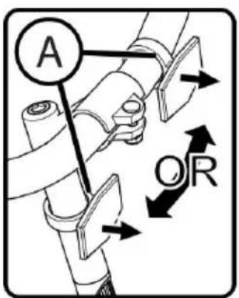
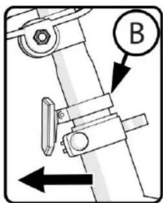
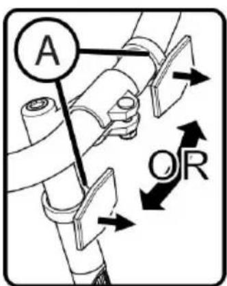
- Position the FRONT Reflector (A) so it points straight forward.
- Tighten Clamp Screw.
- Position Seat Post Reflector (if equipped) (B) so it points straight backwards. Tighten Clamp Screw.
NOTE: Do not over-tighten. This will damage the Clamp.
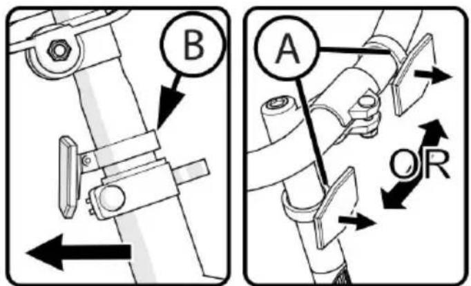
STEP:13
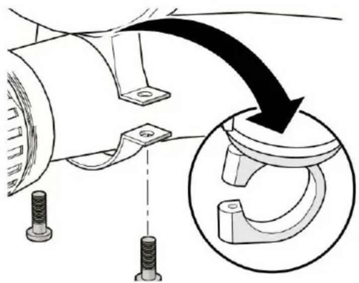
Pegs Installation-Threaded (if equipped)
NOTES
Front and rear pegs may be different sizes. The pegs are optional. You may choose not to install them on the axles. Pegs can be installed on the rear or on one side. The same procedure is used to install pegs on front and rear axles. Front wheel axle is shown.
Threaded pegs:
No additional tools are necessary to install the pegs. Put a peg on each of the axles.
Make sure the peg (A) is fully seated against the frame or fork. Tighten peg securely. Pegs will go over the axle nuts (B).

WARNINGS:
Do not ride beyond your capabilities.
Pegs should be installed by an adult.
Check before each ride.
Ensure there is no damage to the frame, fork, or wheels during installation and use.
Ensure the chain is correctly adjusted after installation.
Ensure wheels are correctly aligned after installation.
If damaged, stop use and replace.
Remember, failure to obey these steps can lead to serious consequences such as the front wheel loosening while riding, potentially causing injury to the rider or others. Your role in safety is crucial.
STEP:14
Handlebar Bell (various models)
Installation:
- Remove screws from Bell.
- Position Bell on handlebar within easy reach, with hands on the handlebar grips.
- Install screws and tighten.
NOTE: Bell may attach with 1 or 2 screws.
Repair and Service
WARNING:
Inspect the product frequently. Failure to inspect the product and make repairs or adjustments, as necessary, can result in injury to the rider or others. Ensure all parts are correctly assembled and adjusted as written in this manual and any "Special Instructions."
Immediately replace any damaged, missing, or badly worn parts with original equipment. Ensure all fasteners are correctly tightened as written in this manual and any "Special Instructions." Parts that are not tight enough can be lost or operate poorly. Over-tightened parts can be damaged. Make sure any replacement fasteners are the correct size and type.
NOTE: Have a bicycle service shop make any repairs or adjustments for which you do not have the correct tools or if the instructions in this or any "Special instructions" are not sufficient.
Coaster Brakes (various models)
These models are equipped with a rear 'coaster' brake that is operated by rotating the crank backward.
Operate the coaster brake as follows: Push the pedals backward to move the chain backward. The chain activates the coaster brake mechanism inside the rear wheel hub.
As you push the pedals backward with increasing force, the braking of the coaster brake increases.
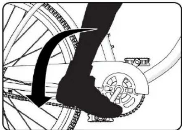
If your bicycle has a caliper brake(s) in addition to the coaster brake, always use the coaster brake as the main brake to stop the bicycle.
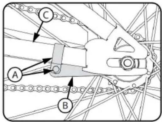
WARNING: If you do not obey the following instructions, injury to the rider or to others can occur: When you ride the bicycle, test the coaster brake and practice using it at a low speed in a level area that is free of obstructions. Every time the bicycle is ridden, make sure the clamp (A) on the brake arm (B) is securely attached to the stay (C) of the bicycle frame. The coaster brake will not work correctly if the brake arm is not attached to the chain stay.
Chain Adjustment
WARNING:
The chain must remain on the sprockets. If the chain comes off the sprockets, the coaster brake will not operate. Do not attempt chain repairs. If there is a problem with the chain, have a bicycle shop make any repairs.

Adjustment:
The chain must be at the correct tightness. If too tight, the bicycle will be difficult to pedal. If too loose, the chain can come off the sprockets. When the chain (C) is at the correct tightness, you can rotate the crank and you can pull it no more than one-half inch (A) away from a straight line as shown.
Adjust the tightness of the chain as follows:
Loosen the axle nuts of the rear wheel.
Move the rear wheel forward or backward as necessary.
NOTE: Make sure the rear wheel is in the center of the bicycle frame. Hold the wheel in this position and tighten securely.
Inspection of the Bearings
Maintenance
Frequently check the bearings of the bicycle. Lubricate the bearings according to the lubrication chart or any time they do not pass the tests.
Head Tube Bearings
The fork should turn freely and smoothly at all times. With the front off the ground, you should not be able to move the fork up, down, or side-to-side in the head tube.
Crank Bearings
The crank should turn freely and smoothly at all times and the front sprockets should not be loose on the crank. You should not be able to move the pedal end of the crank from side-to-side.
Wheel Bearings
Lift each end of the bicycle off the ground and slowly spin the wheel by hand. The bearings are correctly adjusted if: The wheel spins freely and easily. The weight of the spoke reflector, when you put it toward the rear of the bicycle, causes the wheel to spin back and forth several times. There is no side-to-side movement at the wheel rim when you push it to the side with light force.
Gyro Bearings
With the front wheel off the ground, the Gyro Handlebar/Stem/Wheel system should rotate freely and smoothly 360 degrees without binding or hitting any cables.
Caliper Rim Brake System Setup (various models)
● WARNING: You must adjust the front brakes before you ride the bicycle.
NOTE: FRONT AND REAR BRAKE SETUP IS THE SAME.
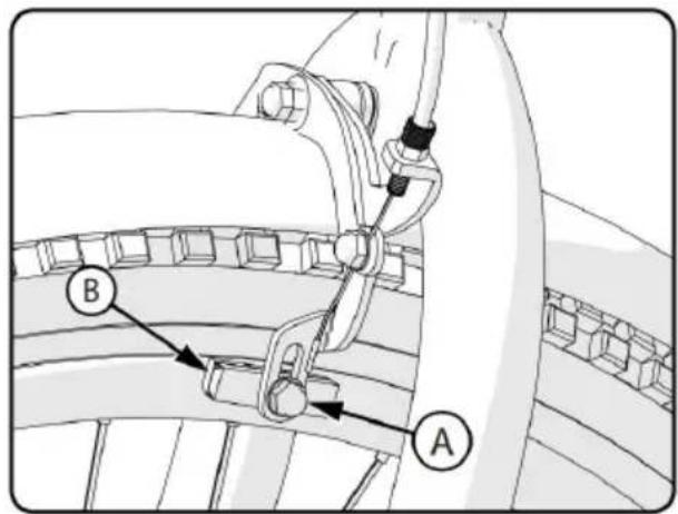
Step One: Put the brake shoes (B) in the correct position:
- Loosen the screw (A) of each brake shoe (B).
- Adjust each brake shoe so it is flat against the rim and aligned with the curve of the rim.
Make sure each brake shoe does not rub the tire.
If the surface of the brake shoe has arrows, make sure the arrows point toward the rear of the bicycle.
Hold each brake shoe in position and tighten the screw.
Step Two: Test the tightness of each brake shoe:
Try to move each brake shoe out of position.
If a brake shoe moves, do Step 1 again, but tighten the nut tighter before. Do this test again, until each brake shoe does not move.
Caliper Rim Brake System Setup - continued
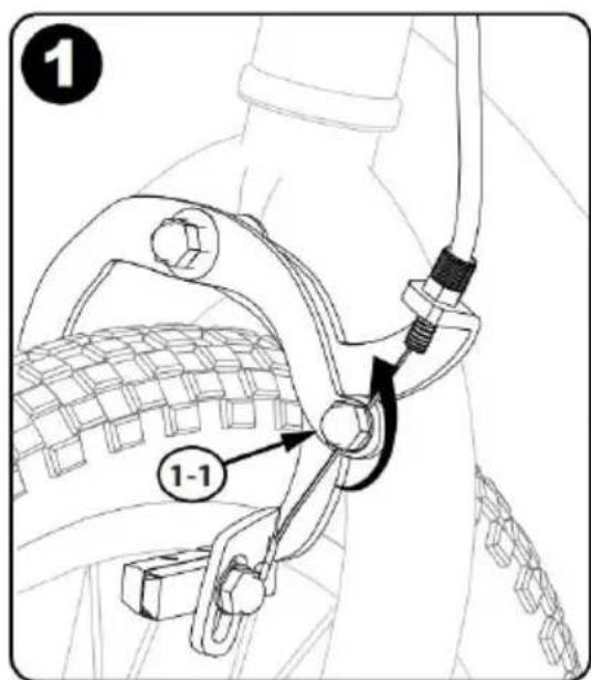
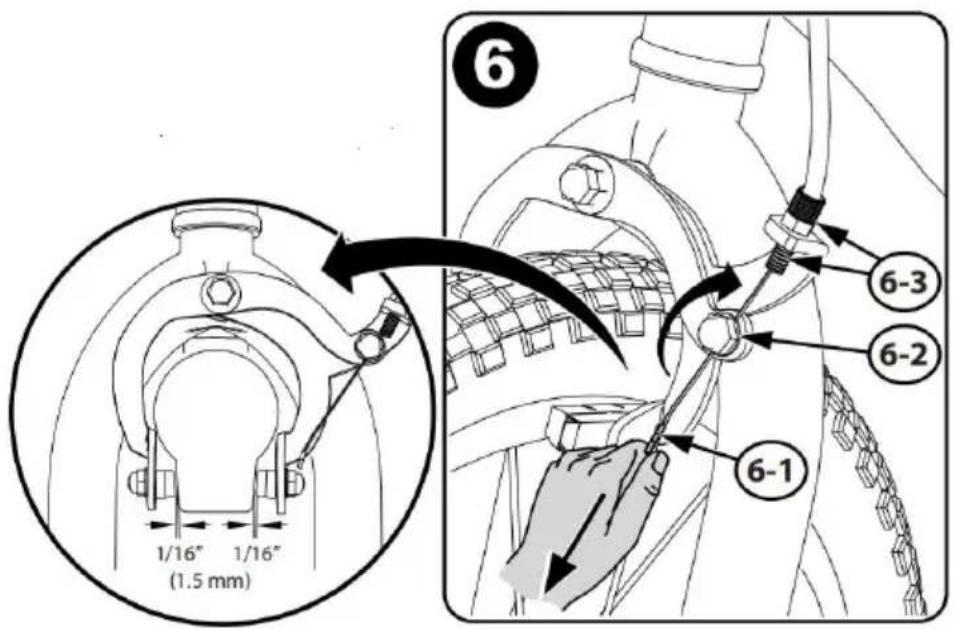
Step 1: Loosen cable nut 1-1 so that the cable is loose.
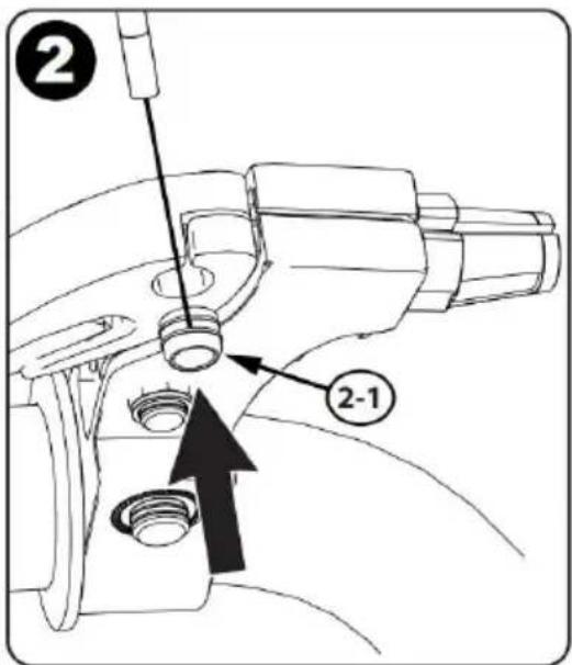
Step 2: Insert cable barrel 2-1 into brake lever.
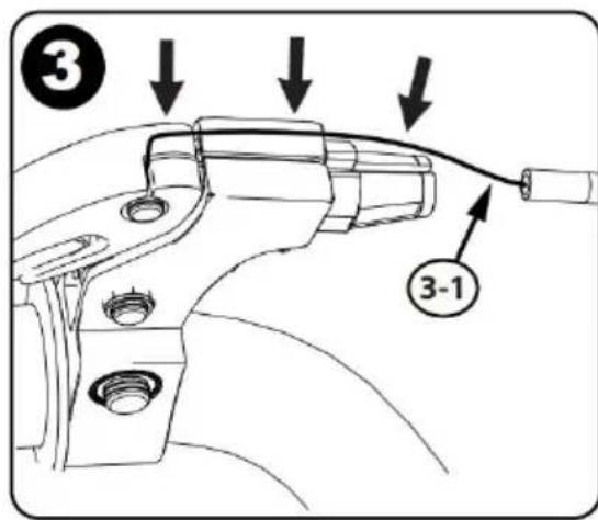
Step 3: Insert brake cable 3-1 into groove as shown.
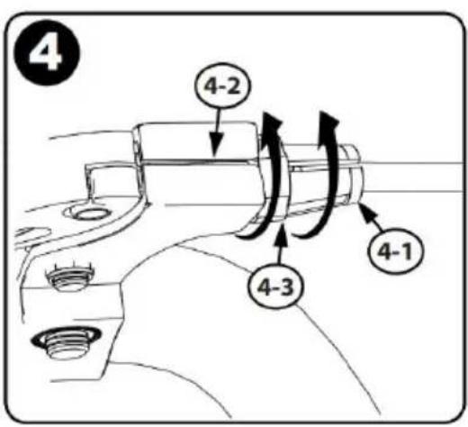
Step 4: Rotate housing (4-1) groove away from cable groove (4-2), tighten housing nut (4-3).
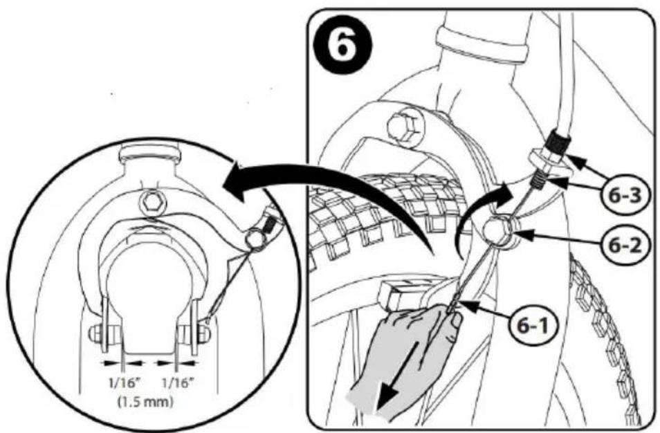
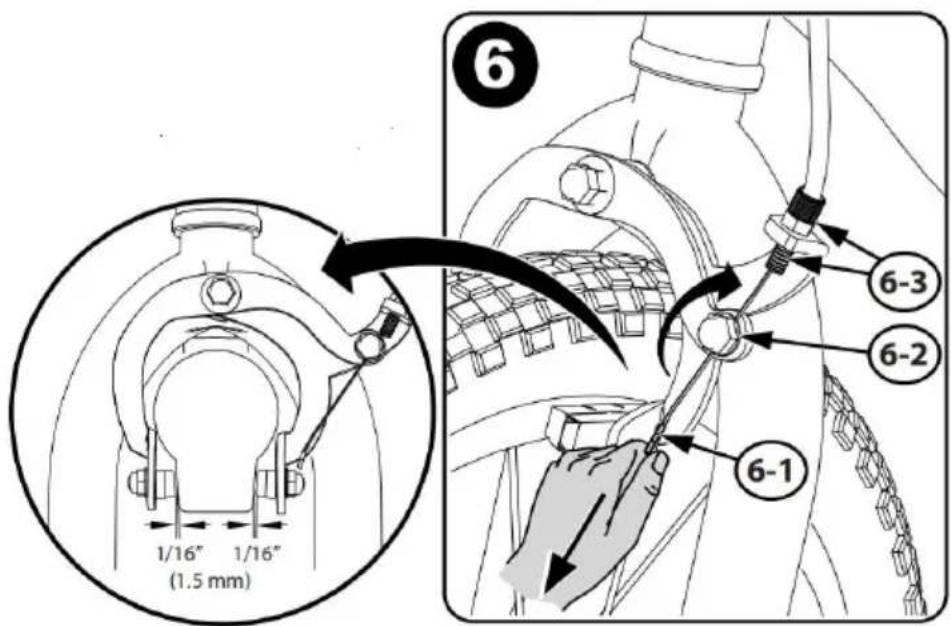
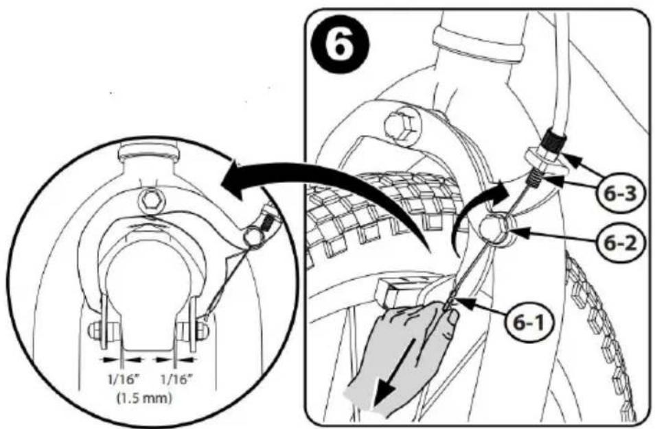
Step 5: Squeeze brake arms (5-1) so that brake pads (5-2) are against rim.
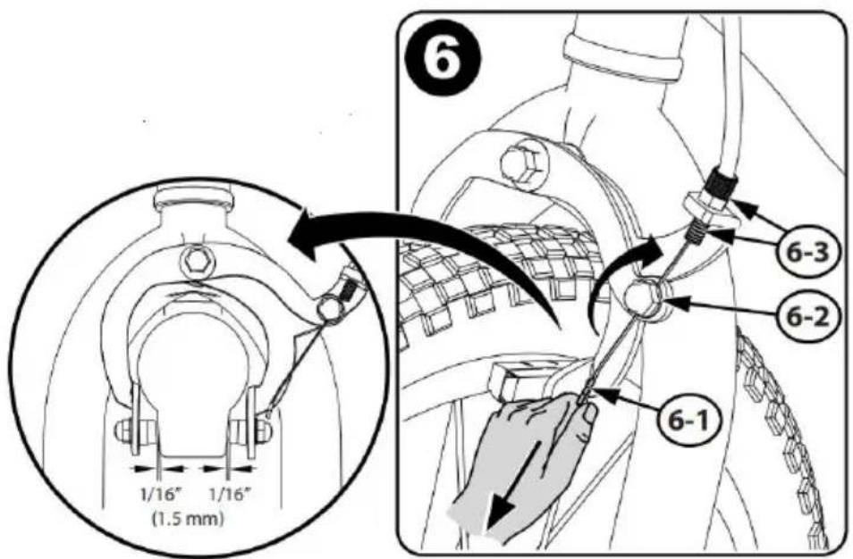
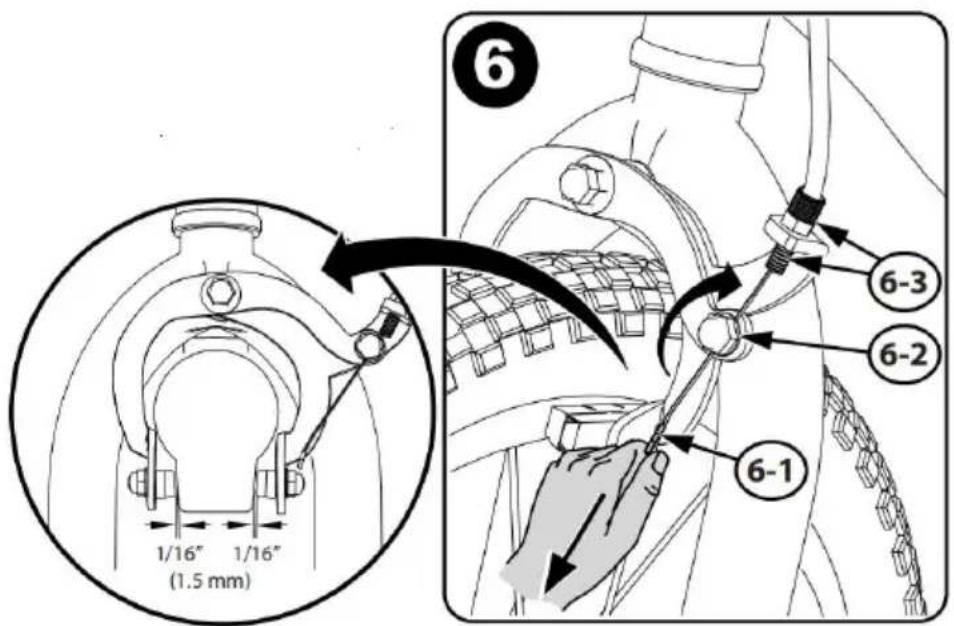
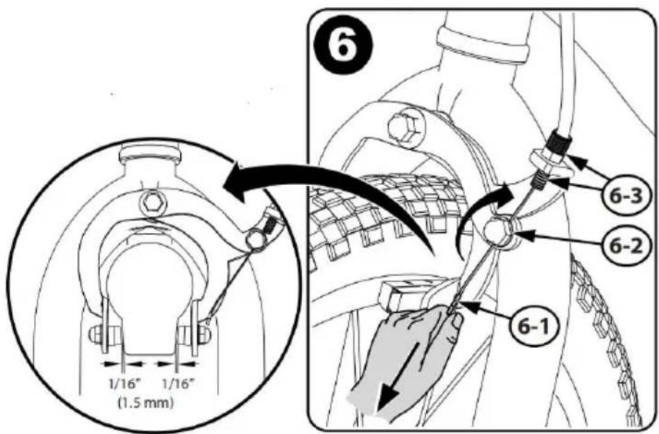
Step 6: Pull Brake Cable (6-1) tight. Tighten Cable Nut (6-2). Adjust Nut (6-3) for 1/16in (1.5mm) Brake Pad clearance.
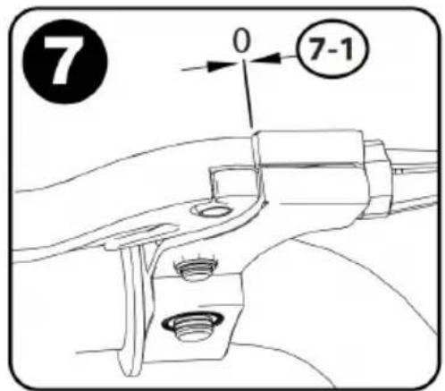
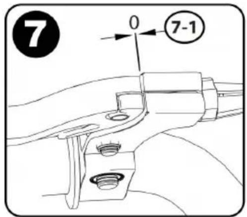
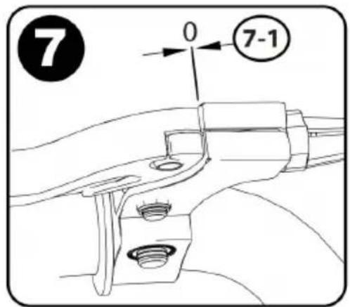
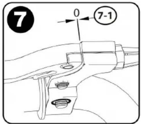
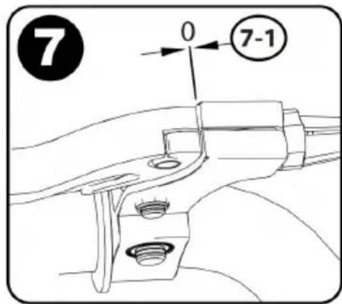
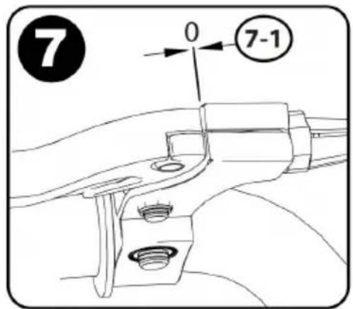
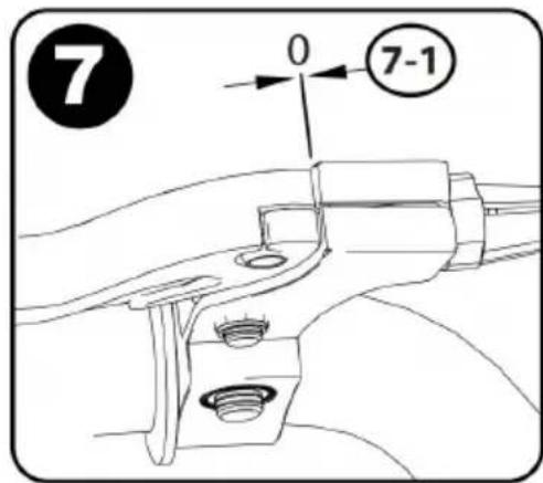
Step 7: Make sure the Brake Lever is not loose (7-1).
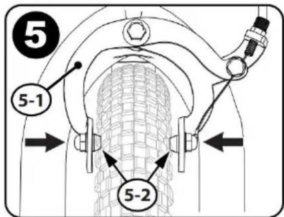
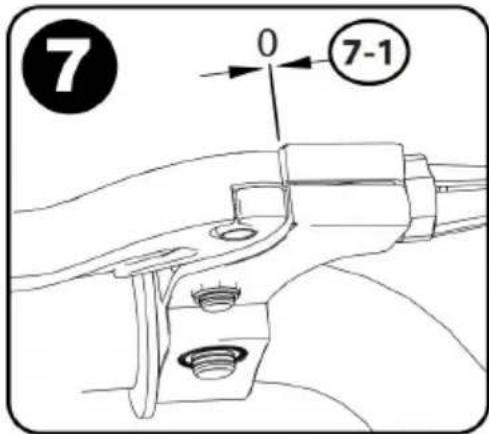
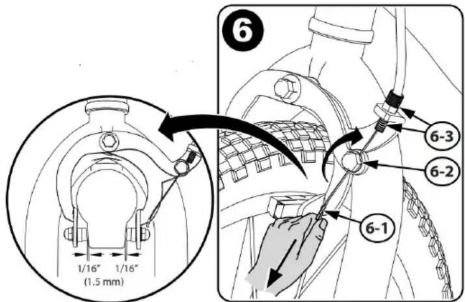
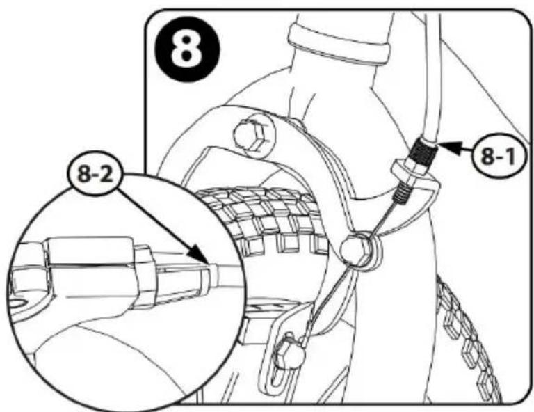
Step 8: Make sure the cable sheaths are fully inserted into the adjustment housing at the Caliper (8-1) and Hand Lever (8-2).
Step 9: Rotate Brake Levers (A) to a comfortable riding position and tighten securely.
Brake Pad Replacement
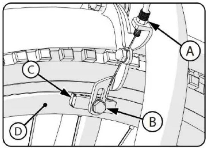
- If necessary, loosen brake cable Adjustment Bolt (A).
- Loosen and remove brake pad Bolt/
Screws (B).
- Remove old Brake Shoe (C).
- Install new Brake Shoe, making sure it is pointing forward and lined evenly with the Wheel Rim (D).
- Tighten brake pad Bolt/Screw according to Torque Chart.
WARNING: Replace Brake Pad with same model and type as original.
Tires
Maintenance:
Frequently check the tire inflation pressure because all tires lose air over time. For extended storage, keep the weight off the tires. Do not use unregulated air hoses to inflate the tires or tubes. An unregulated hose can suddenly over-inflate tires and cause them to burst. Replace worn tires. Warning: Do not ride or sit on the unit if a tire is underinflated. This can damage the tire, inner tube, and rim.
Inflating the Tires:
Use a hand or a foot pump to inflate the tires. Service station meter-regulated air hoses are also acceptable. The maximum inflation pressure is shown on the tire sidewall. If two inflation pressures are shown on the tire sidewall, use the higher pressure for on-road riding and the lower pressure for off-road riding. The lower pressure will provide better tire traction and a more comfortable ride.
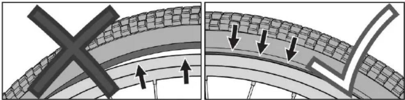
Before adding air to any tire, make sure the edge of the tire (the bead) is the same distance from the rim, all around the rim, on both sides. If the tire does not appear to be seated correctly, release air from the tube until you can push the tire's bead into the rim where necessary. Add air slowly and stop frequently to check the tire seating and the pressure until you reach the correct inflation
pressure.
Lubrication
WARNING:
Do not over-lubricate. If oil gets on the wheel rims or the brake shoes, it can reduce brake performance, and a longer distance will be needed to stop the bicycle. Injury to the rider or others can occur.
The chain can throw excess oil onto the wheel rim. Wipe excess oil off the chain.
Keep all oil off the surfaces of the pedals where your feet rest. Wash all oil off the wheel rims, brake shoes, and pedals using soap and hot water.
And the tires.
Rinse with clean water and dry completely before riding the bicycle. Lubricate the bicycle using light machine oil (20W) according to the following table.
Lubrication Table
| What | When | How |
| Brake Levers | every six months | Put one drop of oil on the pivot point of each brake lever. |
| Caliper Brakes | every six months | Put one drop of oil on the pivot point of each caliper brake. |
| Brake Cables | every six months | Put four drops of oil into both ends of each cable.Allow the oil to soak back along the cable wire. |
| Pedals | every six months | Put four drops of oil where the axles go into the pedals. |
| Chain | every six months | Put one drop of oil on each roller of the chain.Wipe all excess oil off the chain. |
| Gyro Head | every six months | Put 4 drops of oil around the Gyro Head Bearings. |
VEVOR®
TOUGH TOOLS, HALF PRICE
Technical Support and E-Warranty Certificate
www.vevor.com/support
VEVOR®
TOUGH TOOLS, HALF PRICE
MODEL: SS24001; SS24002; SS24003; SS24004; SS24005
⚠ WARNING: CHOKING HAZARD - small parts. Not for children under 3 years.

Rules of the Road
Part Assembly View & List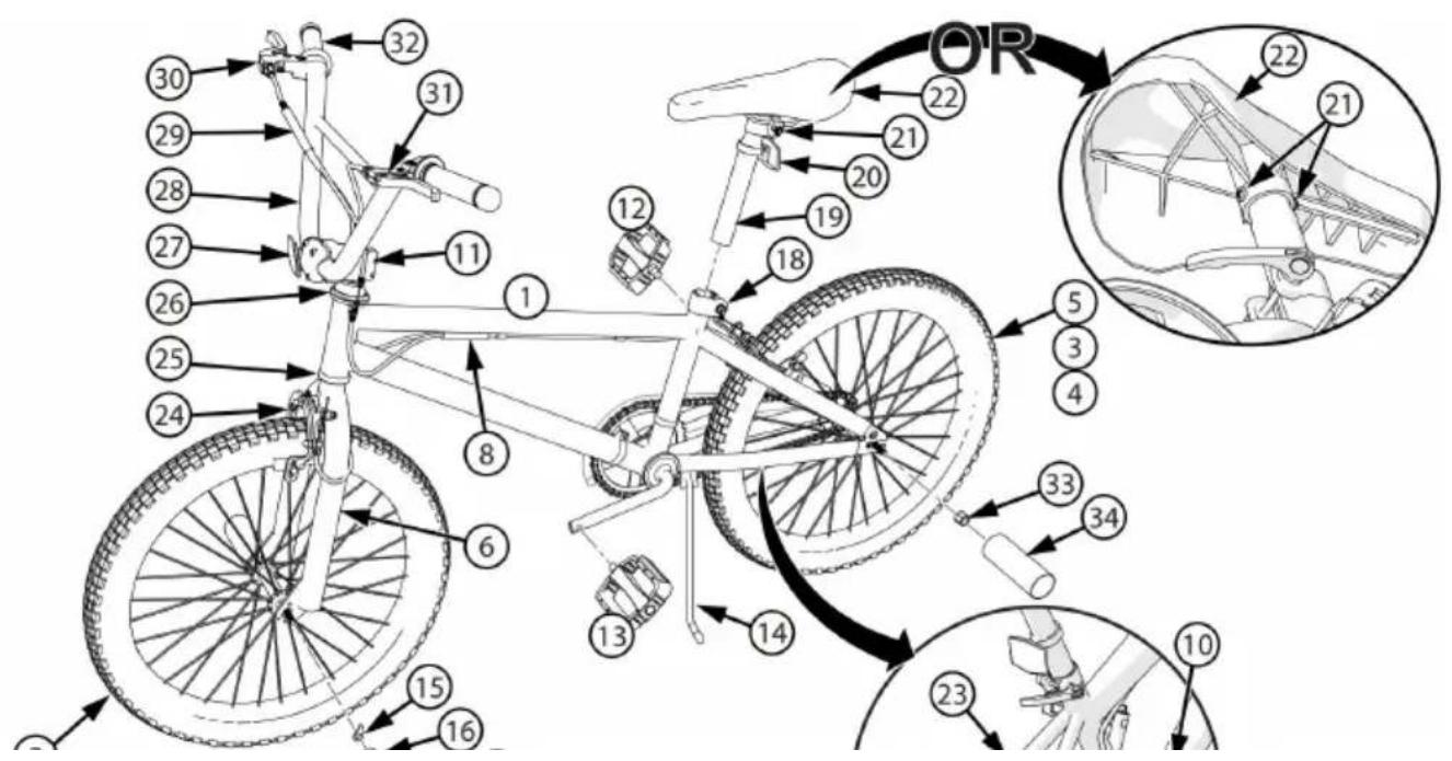
Introduction to Assembly
Tools Needed (not included)
Small Adjustable Wrench
(Jaws must open at least 9/16 inch.)
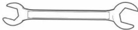
Open-end Wrenches
Flat-blade Screwdriver

Phillips Screwdriver
Slip-Joint Pliers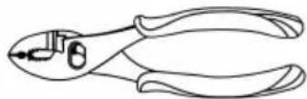
Metric Allen Wrenches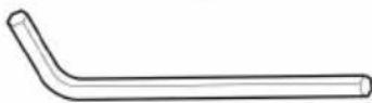
Packing material protection accessories
Step 1:
Step 3:
Handlebar installation - continued
Step 8:
Step 9:
STEP: 10
STEP: 12
(A)
WARNINGS:
Repair and Service
WARNING:
Coaster Brakes (various models)
Chain Adjustment
WARNING:
Adjustment:
Inspection of the Bearings
Maintenance
Caliper Rim Brake System Setup-continued
Tires
Maintenance:
Lubrication
WARNING:
| What | When | How |
| Brake Levers | every six months | Put one drop of oil on the pivot point of each brake lever. |
| Caliper Brakes | every six months | Put one drop of oil on the pivot point of each caliper brake. |
| Brake Cables | every six months | Put four drops of oil into both ends of each cable.Allow the oil to soak back along the cable wire. |
| Pedals | every six months | Put four drops of oil where the axles go into the pedals. |
| Chain | every six months | Put one drop of oil on each roller of the chain.Wipe all excess oil off the chain. |
| Gyro Head | every six months | Put 4 drops of oil around the Gyro Head Bearings. |
VEVOR®
TOUGH TOOLS, HALF PRICE
CHOKING HAZARD-small parts.
Not for children under 3 years.
Rules of the Road
Part Assembly View & List
NOTE: All features, components and accessories are not included on all models.
Introduction to Assembly
Tools Needed (not included)
Small Adjustable Wrench
(Jaws must open at least 9/16 inch.)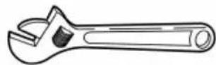
Open-end Wrenches
Flat-blade Screwdriver

Phillips Screwdriver
Slip-Joint Pliers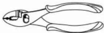
Metric Allen Wrenches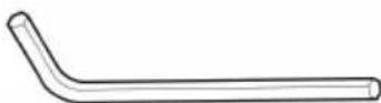
Packing material protection accessories
Step 1:
Step 3:
Step 8:
Step 9:
Seat Installation
STEP:10
STEP: 12
WARNINGS:
Repair and Service
WARNING:
Coaster Brakes (various models)
Chain Adjustment
WARNING:
Adjustment:
Inspection of the Bearings
Maintenance
Caliper Rim Brake System Setup - continued
Tires
Maintenance:
Lubrication
WARNING:
| What | When | How |
| Brake Levers | every six months | Put one drop of oil on the pivot point of each brake lever. |
| Caliper Brakes | every six months | Put one drop of oil on the pivot point of each caliper brake. |
| Brake Cables | every six months | Put four drops of oil into both ends of each cable.Allow the oil to soak back along the cable wire. |
| Pedals | every six months | Put four drops of oil where the axles go into the pedals. |
| Chain | every six months | Put one drop of oil on each roller of the chain.Wipe all excess oil off the chain. |
| Gyro Head | every six months | Put 4 drops of oil around the Gyro Head Bearings. |
VEVOR®
TOUGH TOOLS, HALF PRICE
www.vevor.com/support
VEVOR®
TOUGH TOOLS, HALF PRICE
⚠ WARNING: CHOKING HAZARD - small parts. Not for children under 3 years.

Rules of the Road
Part Assembly View & List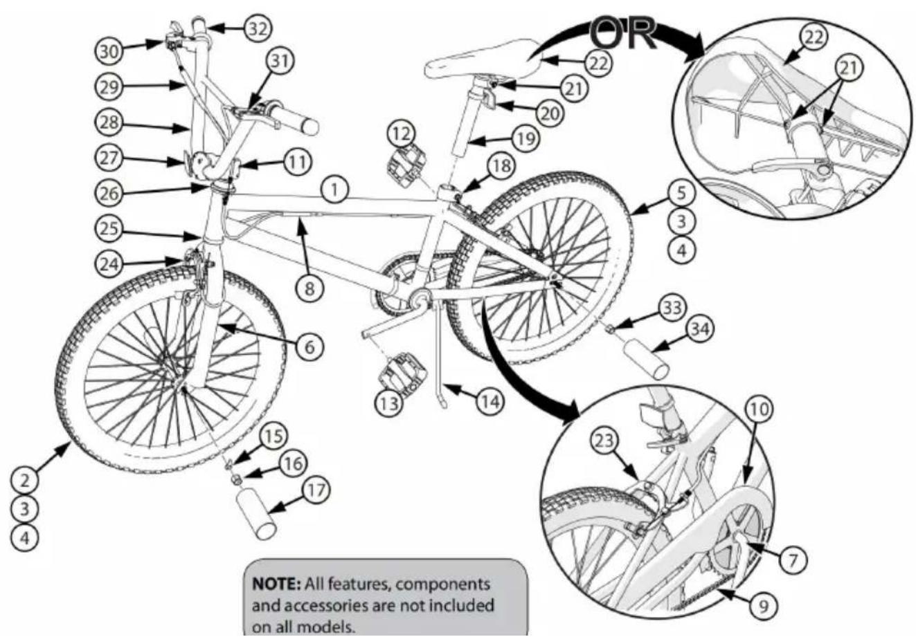
Introduction to Assembly
Tools Needed (not included)
Small Adjustable Wrench
(Jaws must open at least 9/16 inch.)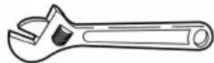
Open-end Wrenches
Flat-blade Screwdriver

Phillips Screwdriver
Slip-Joint Pliers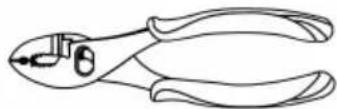
Metric Allen Wrenches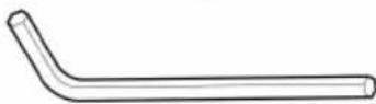
Packing material protection accessories
Step 1:
Step 3:
Step 8:
Step 9:
STEP: 10
STEP: 12
WARNINGS:
Repair and Service
WARNING:
Coaster Brakes (various models)
Chain Adjustment
WARNING:
Adjustment:
Inspection of the Bearings
Maintenance
Caliper Rim Brake System Setup - continued
Tires
Maintenance:
Lubrication
WARNING:
| What | When | How |
| Brake Levers | every six months | Put one drop of oil on the pivot point of each brake lever. |
| Caliper Brakes | every six months | Put one drop of oil on the pivot point of each caliper brake. |
| Brake Cables | every six months | Put four drops of oil into both ends of each cable.Allow the oil to soak back along the cable wire. |
| Pedals | every six months | Put four drops of oil where the axles go into the pedals. |
| Chain | every six months | Put one drop of oil on each roller of the chain.Wipe all excess oil off the chain. |
| Gyro Head | every six months | Put 4 drops of oil around the Gyro Head Bearings. |
VEVOR®
TOUGH TOOLS, HALF PRICE
⚠ WARNING: CHOKING HAZARD - small parts. Not for children under 3 years.

Rules of the Road
Part Assembly View & List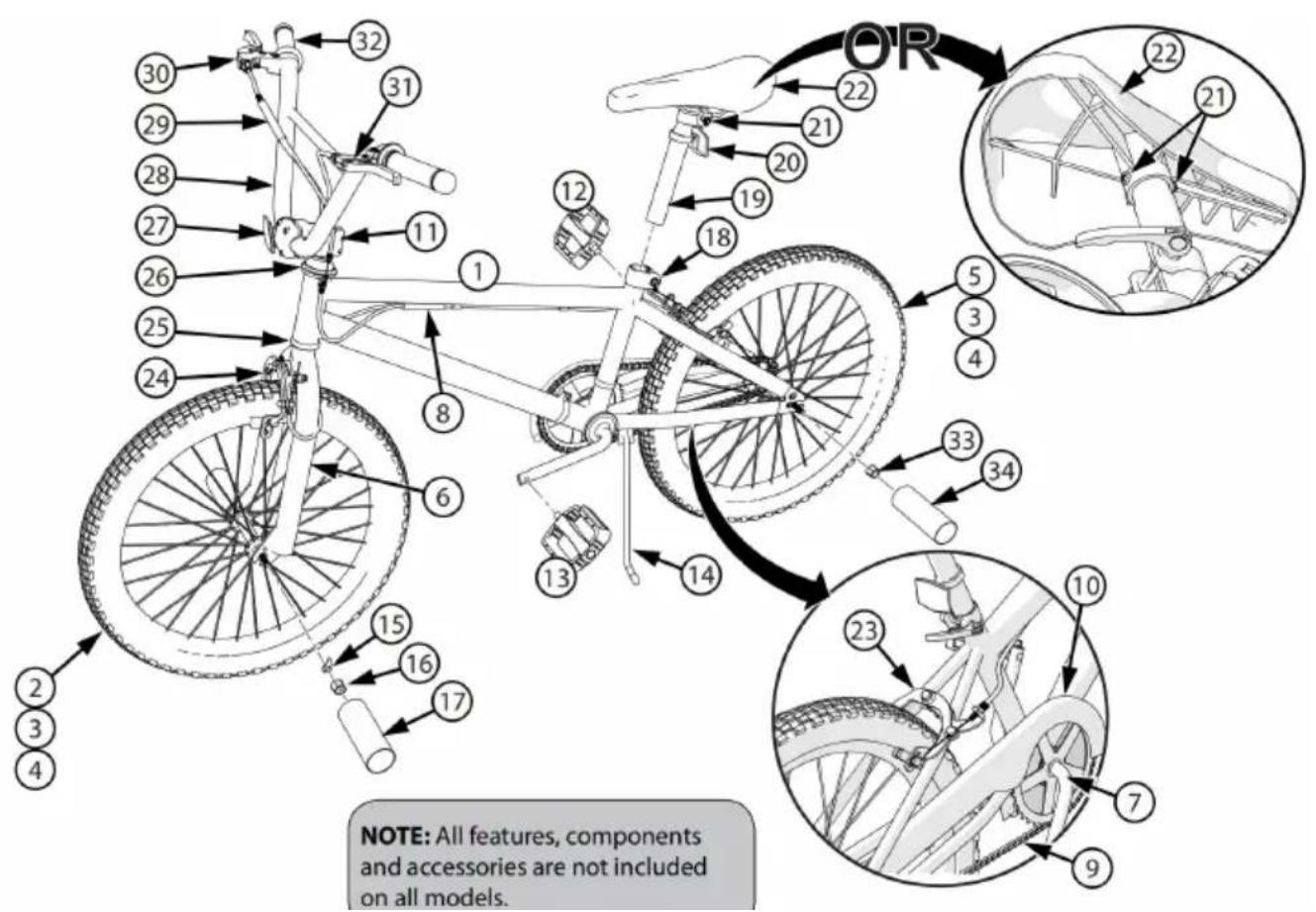
Introduction to Assembly
Tools Needed (not included)
Small Adjustable Wrench
(Jaws must open at least 9/16 inch.)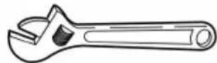
Open-end Wrenches
Flat-blade Screwdriver

Phillips Screwdriver
Slip-Joint Pliers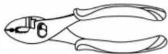
Metric Allen Wrenches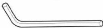
Packing material protection accessories
Step 1:
Step 3:
Step 8:
Step 9:
STEP: 10
STEP: 12

WARNINGS:
Repair and Service
WARNING:
Coaster Brakes (various models)
Chain Adjustment
WARNING:
Adjustment:
Inspection of the Bearings
Maintenance
Caliper Rim Brake System Setup - continued
Tires
Maintenance:
Lubrication
WARNING:
| What | When | How |
| Brake Levers | every six months | Put one drop of oil on the pivot point of each brake lever. |
| Caliper Brakes | every six months | Put one drop of oil on the pivot point of each caliper brake. |
| Brake Cables | every six months | Put four drops of oil into both ends of each cable.Allow the oil to soak back along the cable wire. |
| Pedals | every six months | Put four drops of oil where the axles go into the pedals. |
| Chain | every six months | Put one drop of oil on each roller of the chain.Wipe all excess oil off the chain. |
| Gyro Head | every six months | Put 4 drops of oil around the Gyro Head Bearings. |
VEVOR®
TOUGH TOOLS, HALF PRICE
CHOKING HAZARD - small parts.
Not for children under 3 years.

Rules of the Road
Part Assembly View & List
Introduction to Assembly
Tools Needed (not included)
Small Adjustable Wrench
(Jaws must open at least 9/16 inch.)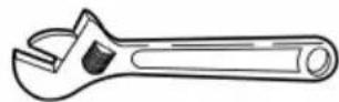
Open-end Wrenches
Flat-blade Screwdriver

Phillips Screwdriver
Slip-Joint Pliers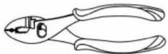
Metric Allen Wrenches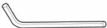
Packing material protection accessories
Step 1:
Step 3:
Step 8:
Step 9:
KROK:10
KROK:12
WARNINGS:
Repair and Service
WARNING:
Coaster Brakes (various models)
Chain Adjustment

WARNING:
Modification:
Inspection of the Bearings
Maintenance
Head Tube Bearings
Caliper Rim Brake System Setup - continued
Lubrication
WARNING:
| What | When | How |
| Brake Levers | every six months | Put one drop of oil on the pivot point of each brake lever. |
| Caliper Brakes | every six months | Put one drop of oil on the pivot point of each caliper brake. |
| Brake Cables | every six months | Put four drops of oil into both ends of each cable.Allow the oil to soak back along the cable wire. |
| Pedals | every six months | Put four drops of oil where the axles go into the pedals. |
| Chain | every six months | Put one drop of oil on each roller of the chain.Wipe all excess oil off the chain. |
| Gyro Head | every six months | Put 4 drops of oil around the Gyro Head Bearings. |
VEVOR®
TOUGH TOOLS, HALF PRICE
www.vevor.com/support
VEVOR®
TOUGH TOOLS, HALF PRICE
Technical Support and e-Warranty Certificate www.vevor.com/support
BMX bike
MODEL: SS24001; SS24002; SS24003; SS24004; SS24005
NEED HELP? CONTACT US!
⚠ WARNING: CHOKING HAZARD - small parts. Not for children under 3 years.

Rules of the Road
Part Assembly View & List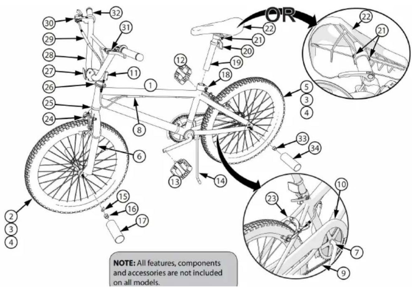
Introduction to Assembly
Tools Needed (not included)
Small Adjustable Wrench
(Jaws must open at least 9/16 inch.)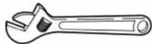
Open-end Wrenches
Flat-blade Screwdriver

Phillips Screwdriver
Slip-Joint Pliers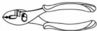
Metric Allen Wrenches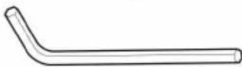
Packing material protection accessories
Step 1:
Step 3:
Two bolt stems:
Step 7:
Step 8:
Step 9:
STEP: 10
STEP: 12
WARNINGS:
Repair and Service
WARNING:
Coaster Brakes (various models)
Chain Adjustment
WARNING:
Adjustment:
Inspection of the Bearings
Maintenance
Caliper Rim Brake System Setup - continued
Step 1: Loosen cable nut 1-1 so that the cable is loose.
Step 2: Insert cable barrel 2-1 into the brake lever.
Tires
Maintenance:
Lubrication
WARNING:
| What | When | How |
| Brake Levers | every six months | Put one drop of oil on the pivot point of each brake lever. |
| Caliper Brakes | every six months | Put one drop of oil on the pivot point of each caliper brake. |
| Brake Cables | every six months | Put four drops of oil into both ends of each cable.Allow the oil to soak back along the cable wire. |
| Pedals | every six months | Put four drops of oil where the axles go into the pedals. |
| Chain | every six months | Put one drop of oil on each roller of the chain.Wipe all excess oil off the chain. |
| Gyro Head | every six months | Put 4 drops of oil around the Gyro Head Bearings. |
VEVOR®
TOUGH TOOLS, HALF PRICE
www.vevor.com/support
VEVOR®
TOUGH TOOLS, HALF PRICE
⚠ WARNING: CHOKING HAZARD - small parts. Not for children under 3 years.

Rules of the Road
NOTE: All features, components and accessories are not included on all models.
Introduction to Assembly
Tools Needed (not included)
Small Adjustable Wrench
(Jaws must open at least 9/16 inch.)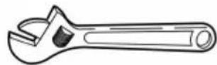
Open-end Wrenches
Flat-blade Screwdriver

Phillips Screwdriver
Slip-Joint Pliers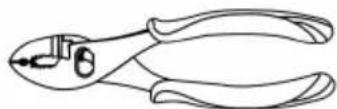
Metric Allen Wrenches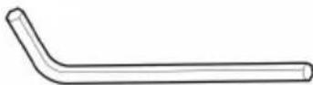
Packing material protection accessories
Step 1:
Step 3:
Gyrobroms installation - Front brake cable installation
Step 8:
Step 9:
Seat installation
STEP:10
STEP:12
Reflector installation (as equipped)
Reflector installation:
22. Position the FRONT reflector (A)
so it points straight ahead.
WARNINGS:
Repair and Service
WARNING:
Coaster Brakes (various models)
Chain Adjustment
WARNING:
Adjustment:
Inspection of the Bearings
Maintenance
Head Tube Bearings
Caliper Rim Brake System Setup - continued
Tires
Maintenance:
Lubrication
WARNING:
| What | When | How |
| Brake Levers | every six months | Put one drop of oil on the pivot point of each brake lever. |
| Caliper Brakes | every six months | Put one drop of oil on the pivot point of each caliper brake. |
| Brake Cables | every six months | Put four drops of oil into both ends of each cable.Allow the oil to soak back along the cable wire. |
| Pedals | every six months | Put four drops of oil where the axles go into the pedals. |
| Chain | every six months | Put one drop of oil on each roller of the chain.Wipe all excess oil off the chain. |
| Gyro Head | every six months | Put 4 drops of oil around the Gyro Head Bearings. |
VEVOR®
TOUGH TOOLS, HALF PRICE
www.vevor.com/support



- BMX BIKE
- NEED HELP? CONTACT US
- OPERATION SAFETY
- MEANINGS OF WARNINGS
- WARNING - FREEWHEEL (RIM) BRAKES
- WARNING
- RULES OF THE ROAD
- USE EXTRA CAUTION IN WET WEATHER
- AVOID THESE HAZARDS TO PREVENT LOSS OF CONTROL OR DAMAGE TO YOUR WHEELS
- PART ASSEMBLY VIEW & LIST
- INTRODUCTION TO ASSEMBLY
- TOOLS NEEDED (NOT INCLUDED)
- PACKING MATERIAL PROTECTION ACCESSORIES
- STEP
- INSTALLING THE FRONT WHEEL
- HANDLEBAR AND STEM INSTALLATION - NO GYRO BRAKE
- QUILL TYPE STEM
- THREADLESS TYPE STEMS
- WARNINGS
- HANDLEBAR INSTALLATION - CONTINUED
- TWO BOLT STEM
- STEM AND HANDLEBAR SETUP - GYRO BRAKE
- GYRO STEM AND BRAKE SETUP
- GYRO STEM AND BRAKE SETUP - CONTINUED
- GYRO BRAKE SETUP - FRONT BRAKE CABLE INSTALL
- GYRO BRAKE SETUP - FRONT BRAKE CABLE INSTALL - CONTINUED
- TESTING STEM AND HANDLEBAR TIGHTNESS
- SEAT INSTALLATION
- SEAT AND SEAT POST SETUP
- SEAT BOLT MOUNT (VARIOUS MODELS)
- PEDAL INSTALLATION
- REFLECTOR INSTALLATION (AS EQUIPPED)
- REFLECTOR INSTALLATION
- PEGS INSTALLATION-THREADED (IF EQUIPPED)
- NOTES
- THREADED PEGS
- HANDLEBAR BELL (VARIOUS MODELS)
- INSTALLATION
- REPAIR AND SERVICE
- COASTER BRAKES (VARIOUS MODELS)
- CHAIN ADJUSTMENT
- ADJUSTMENT
- ADJUST THE TIGHTNESS OF THE CHAIN AS FOLLOWS
- INSPECTION OF THE BEARINGS
- MAINTENANCE
- HEAD TUBE BEARINGS
- CRANK BEARINGS
- WHEEL BEARINGS
- GYRO BEARINGS
- CALIPER RIM BRAKE SYSTEM SETUP (VARIOUS MODELS)
- STEP TWO: TEST THE TIGHTNESS OF EACH BRAKE SHOE
- CALIPER RIM BRAKE SYSTEM SETUP - CONTINUED
- BRAKE PAD REPLACEMENT
- TIRES
- INFLATING THE TIRES
- LUBRICATION
- VEVOR®
- TOUGH TOOLS, HALF PRICE
- CALIPER RIM BRAKE SYSTEM SETUP-CONTINUED
- KROK
- MODIFICATION
- TWO BOLT STEMS
- GYROBROMS INSTALLATION - FRONT BRAKE CABLE INSTALLATION
Brand : Vevor
Model : SS24005
Category : Bicycles