
M400C - Measuring equipment Vevor - Free user manual and instructions
Find the device manual for free M400C Vevor in PDF.
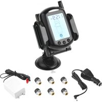


| Product Type | Solar Tire Pressure Monitoring System (TPMS) |
| Brand | Vevor |
| Model | M400C |
| Monitor Dimensions | 82 x 55 x 23 mm |
| Sensor Dimensions | 24 x 21 x 21 mm |
| Sensor Weight | 11 g (±1 g) |
| Monitor Power Supply | Built-in rechargeable lithium battery, charges via 12/24 V DC |
| Sensor Power Supply | CR1632 button cell (3 V DC) |
| Pressure Measurement Range | 0 to 232 psi (0 to 16 bar) |
| Pressure Accuracy | ±4.35 psi (±0.3 bar) |
| Temperature Measurement Range | -10 °C to 85 °C (14 °F to 185 °F) |
| Temperature Accuracy | ±3 °C |
| Transmission Frequency | 433.92 MHz |
| Transmission Range | Up to 20 m (65 ft); amplifier recommended for trailers |
| Main Functions | Pressure and temperature monitoring, fast/slow leak alarms, overpressure, underpressure, high temperature (2 levels), low battery indicator |
| Sleep Mode | Automatic sleep after 15 min of vehicle inactivity |
| Maintenance and Cleaning | Clean the monitor with a soft, dry cloth. Do not use chemicals. |
| Safety | Visual (red LED) and audible alarms. Compliant with FCC Part 15. |
| Spare Parts and Repairability | External sensors, CR1632 batteries, charging cable; technical support via www.vevor.com/support |
| General Information | Electronic warranty, manufacturer: Shanghaimuxinmuyeyouxiangongsi |
Frequently Asked Questions - M400C Vevor
User questions about M400C Vevor
0 question about this device. Answer the ones you know or ask your own.
Ask a new question about this device
Download the instructions for your Measuring equipment in PDF format for free! Find your manual M400C - Vevor and take your electronic device back in hand. On this page are published all the documents necessary for the use of your device. M400C by Vevor.
USER MANUAL M400C Vevor
Technical Support and E-Warranty Certificate www.vevor.com/support
SOLAR TPMS
MODEL: M400C
We continue to be committed to provide you tools with competitive prices. "Save Half", "Half Price" or any other similar expressions used only represent an estimate of savings you might benefit from buying certain tools with us compared to the major top brands and do not necessarily mean to cover all categories of tools offered by us. You are kindly reminded to verify carefully when you are placing an order if you are actually saving half in comparison with the top major brands.
VEVOR®
TOUGH TOOLS, HALF PRICE
SOLAR TPMS
MODEL: M400C
NEED HELP? CONTACT US!
Have product questions? Need technical support? Please feel free to contact us:
Technical Support and E-Warranty Certificate www.vevor.com/support
This is the original instruction. Please read all manual instructions carefully before operating. VEVOR reserves a clear interpretation of our user manual. The appearance of the product shall be subject to the product you received. Please forgive us that we won't inform you again if there are any technology or software updates on our product.
1. Instruction
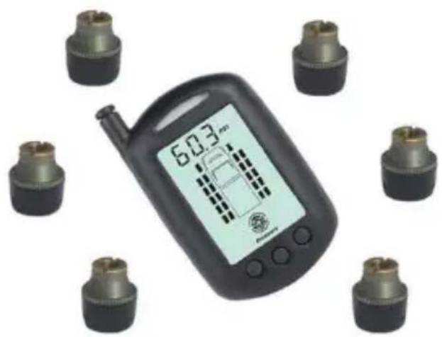
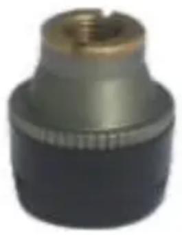
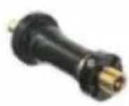
Congratulations on purchasing the new TYRE PRESSURE MONITORING SYSTEM (TPMS). This system is a safety system for monitoring vehicle's tyre air pressure and temperature. It consists of externally mounted tyre pressure wireless sensors fitted to the vehicle's tyre valve and a hand-held monitor. The sensor will monitor the tyre's air pressure and temperature. The sensor transmits the tyre pressure and temperature information to the dash-mounted/hand-held monitor. The monitor can be placed on the dashboard, on the sun visor or mounted in any convenient place in the vehicle.
SENSOR
2. Function
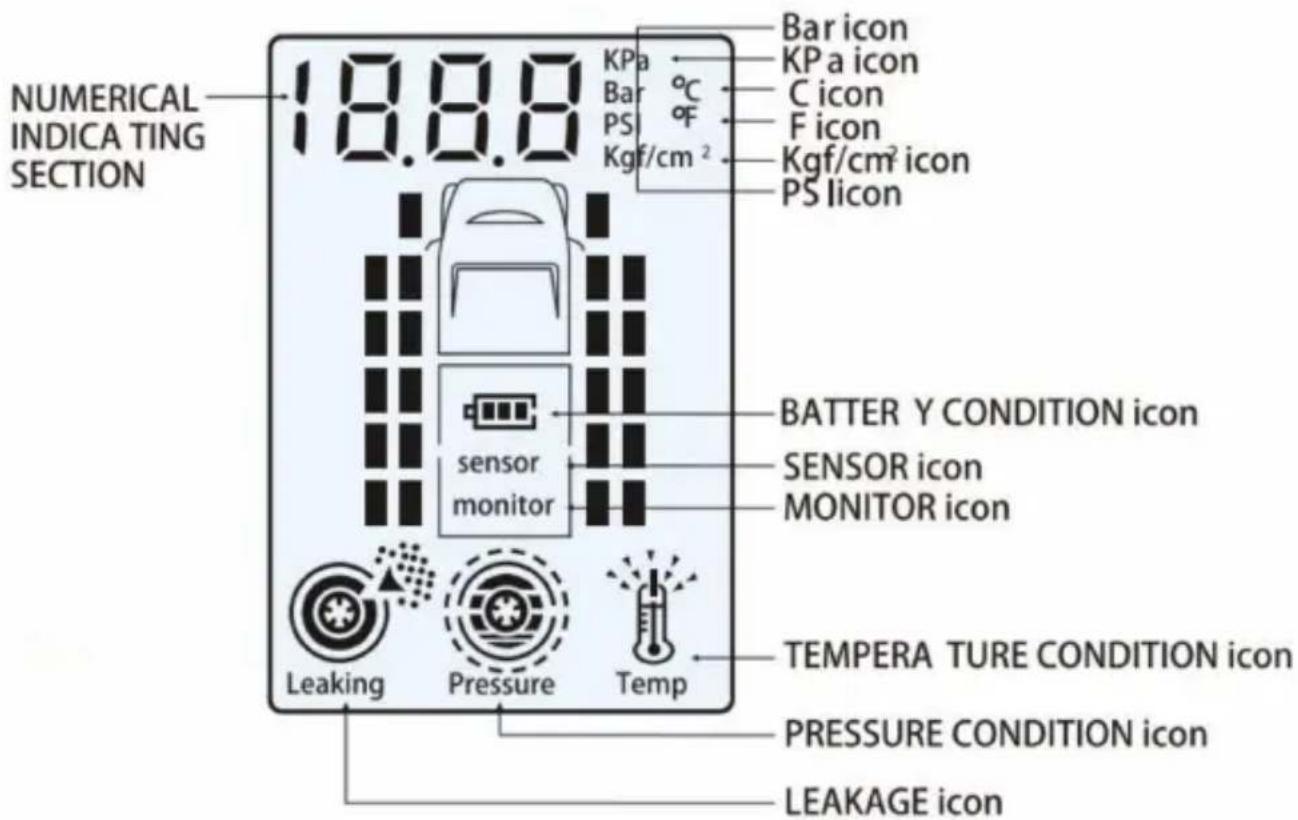
The monitor's function is to receive the temperature and pressure information transmitted from the sensors fitted to each tire and display this information on the screen in the specific
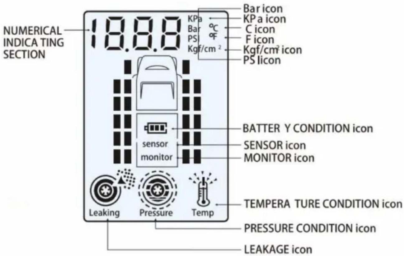
units of measurement of your choice. The monitor will emit an alarm when a tire pressure or temperature varies markedly from the targeted tire pressure and/or temperature (refer to section 4). The system will detect high or low air pressure as well as high temperature or rapid leakage from the tires. The monitor will flash a red warning LED lamp and an alarm will sound to remind the operator to check if the tires are high or low in air pressure, if there is leakage, a high temperature condition, if the monitor's battery is low, or if there is a problem with a sensor. This advanced tire monitoring system offers these great features and benefits, is reliable, lightweight, and compact.

3. Installation & Operating Instructions
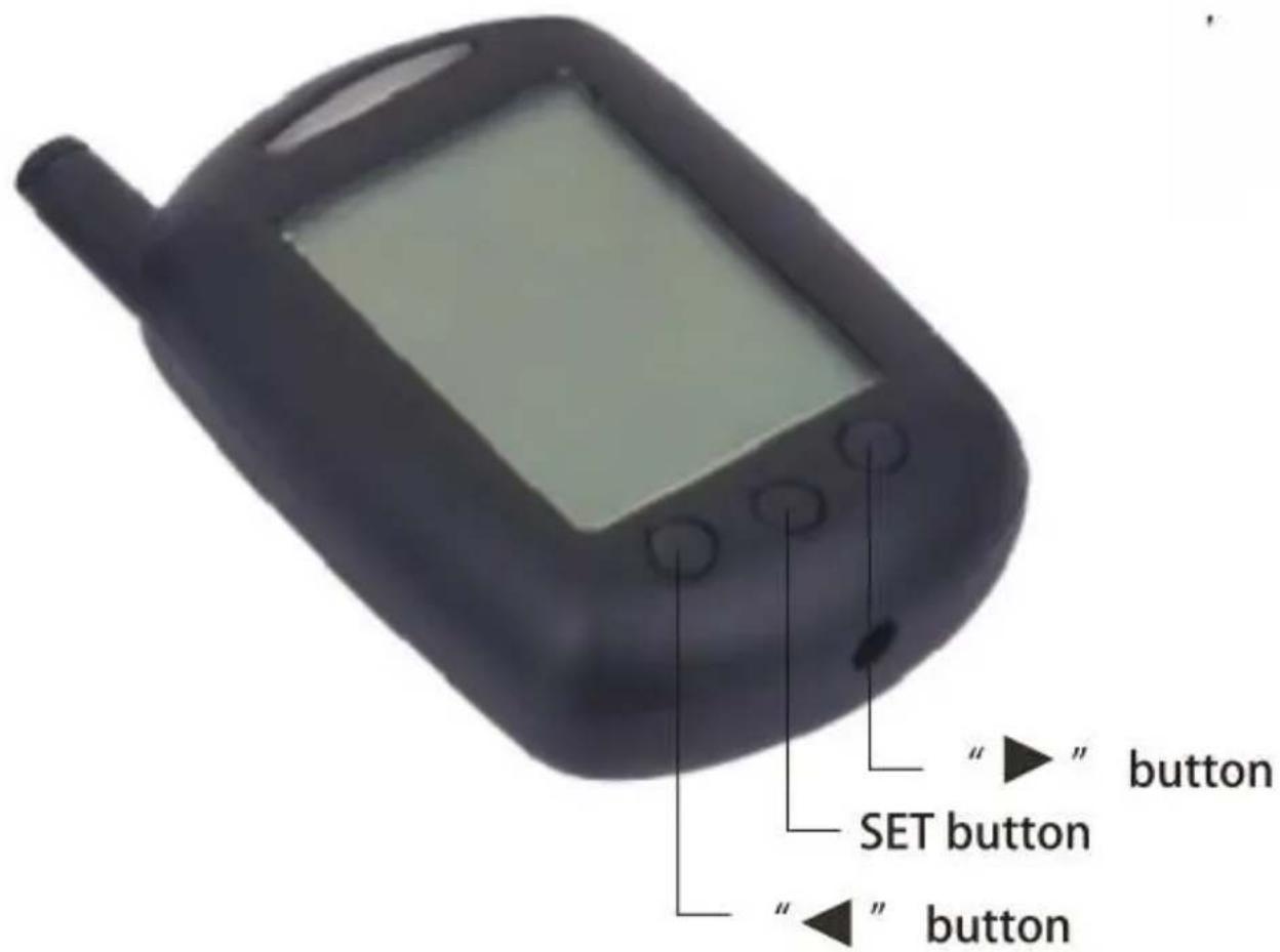
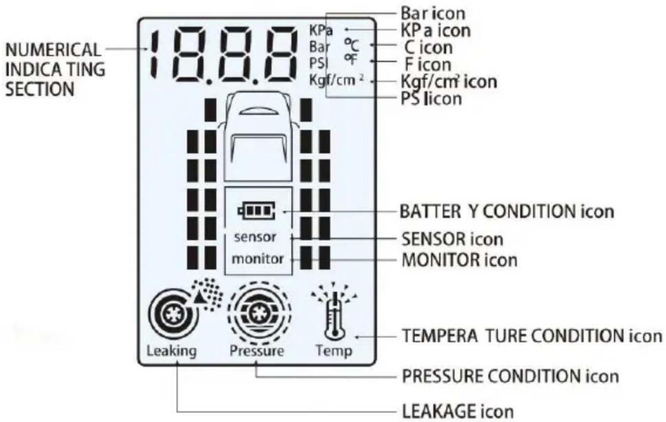
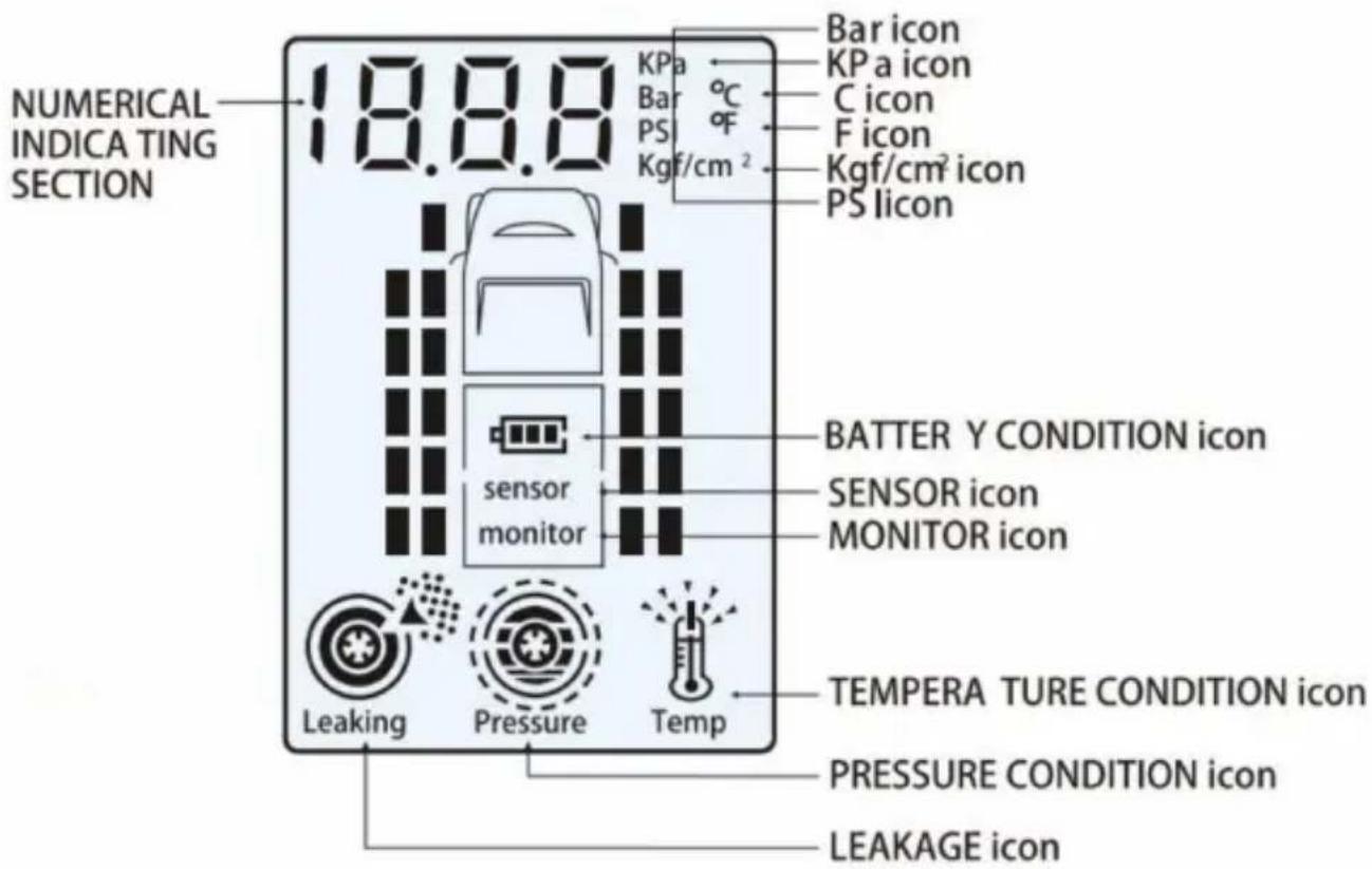
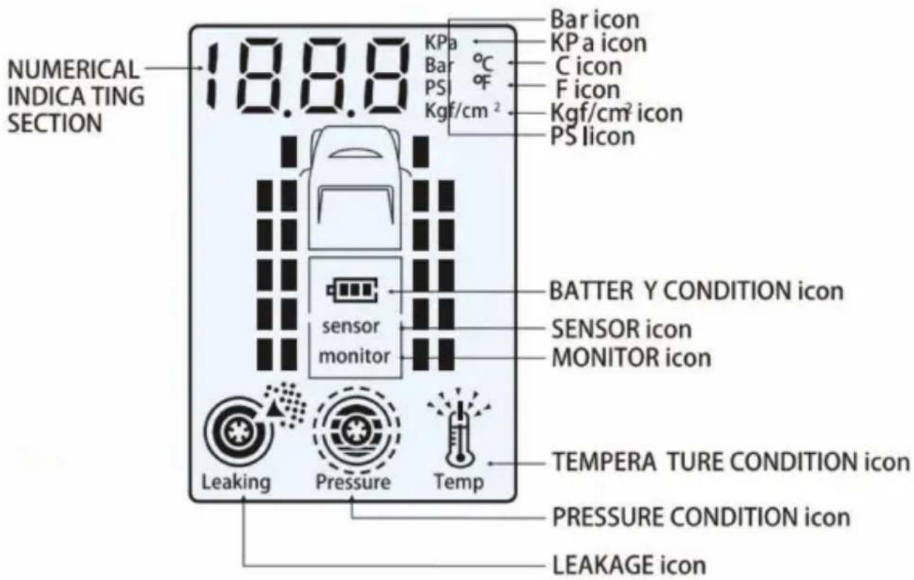
The following instructions show the identification of operating buttons of the monitor.
The following instructions show the identification of the monitor's operating buttons.
Temperature Units Conversion
F=9C/5+32 Note: C=Celsius; F=Fahrenheit
Pressure Units Conversion
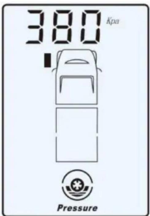
1 Bar=14.5 psi 1 Bar=100 kPa 1 Bar=1.02 kgf/cm²
Please ensure the monitor is fully charged and in the tyre alignment mode before installing the tyre sensors.
Please ensure the monitor is fully charged and in the tyre alignment mode before installing the tyre sensors.
Before installing sensors and setting the monitor, make sure you have inflated the vehicle's tyres to your required pressures.
Hold down the " " and " " buttons simultaneously on the monitor for 5 seconds to enter tyre alignment mode, and press either " " or " " button to select the specific tyre that needs to be aligned.
Hold down the " " and " " buttons simultaneously on the monitor for 5 seconds to enter tyre alignment mode, and press either " " or " " button to select the specific tyre that needs to be aligned.
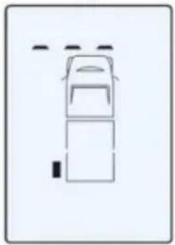
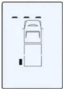
Screw a sensor to the tyre valve stem and the current pressure will be displayed against the corresponding flashing tyre icon on the screen. Once the tyre is aligned successfully, the green light appears on the monitor. The red LED light appears on the monitor if the sensor hasn't been aligned, and "---" also appears on the monitor.
Note: If the sensor is to be removed from one valve and fitted to another valve, you must delete the current setting on the monitor and realign this sensor to the new tyre. To delete an aligned sensor from a tyre, hold down the SET button for 5 seconds.
When you exit the alignment mode, by again holding down the "◀" and "▶" buttons simultaneously on the monitor for 5
seconds to check the pressures and temperatures, the monitor will indicate the data of the selected tyre. Click through to ensure all tyre pressures and temperature details are in accordance with your requirements. After your checks are completed, the backlight will go out and the monitor will indicate the tyre pressure of the selected tyre.
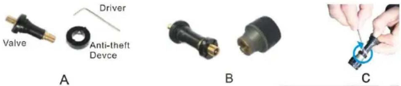
Installation of the Sensor and Anti-theft Device
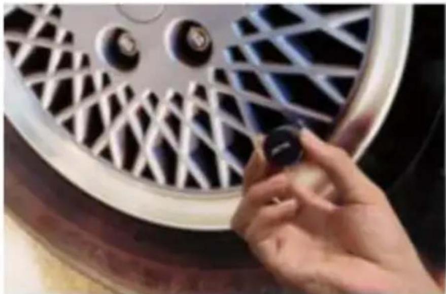
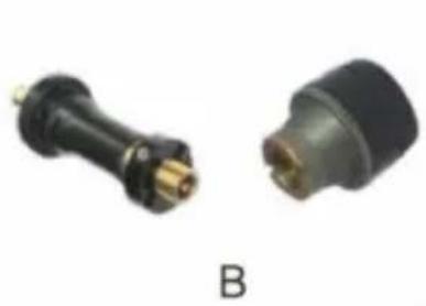
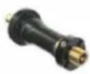
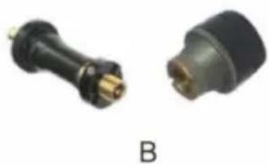
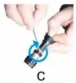
The sensor has an anti-theft ring to prevent the sensors from being stolen. Firstly, place the anti-theft ring over the valve stem, with one side of the inner hexagon facing out, place the hexagon head of the sensor into the inner hexagon and then screw down the sensor; finally, place the inner hexagon screws of the anti-theft device and tighten with the key provided. Please refer to the right graphics A, B and C when installing the rings. It's very simple to install the sensors. Screw a sensor to each tyre valve stem as the picture shows.
Note:
- Always install the sensor when the tyre is cold.
- Please check each tyre valve is not damaged.
- Check to ensure there are no leaks and the sensors are firmly secured to each tyre valve.
Installation of the Monitor
The monitor can be mounted using the pedestal or brackets supplied. The monitor can be fixed to a suitable surface in the vehicle, sun visor, dashboard, etc. It has a built-in lithium battery, or you may wish to use a power source from within the vehicle's power socket to charge or operate the monitor.
Standard Pressure Setting
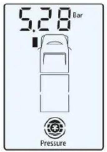
Hold down the set button of the monitor for 5 seconds to enter into the setting mode, as the graphic A, B and C shows. Press "◀" or "▶" button to set the required pressure, and then
quickly press the SET button to scroll through to the next tyre and repeat this sequence to set the remaining tyres.
Note:
It is recommended to set tyre pressures at those recommended by the manufacturer listed in the vehicle's handbook.
A
B
C
After you have completed setting all the tyre pressures, then set your preferred units of temperature and pressure measurement, "kpa", "Bar", "PSI" and "kgf/cm?" for pressure units and "F" and "C" for temperature, by pressing the " " or " " button. The corresponding Hold down SET button for 5 seconds to exit the Standard Pressure Setting mode.
Examination of the Tyre Condition
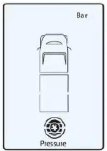
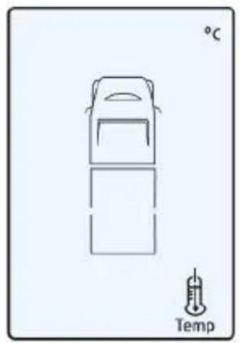
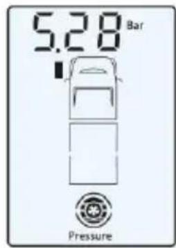
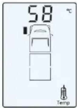
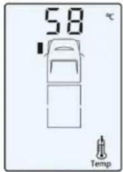
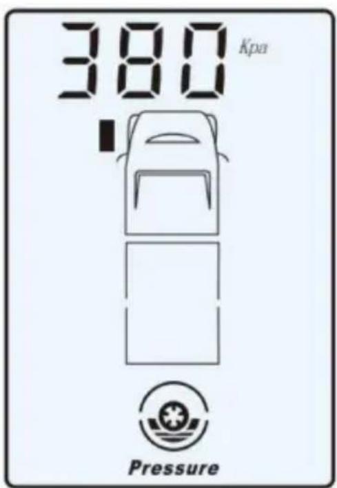
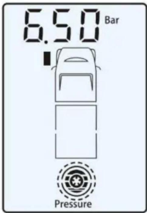
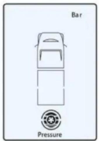
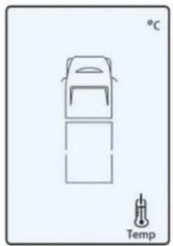
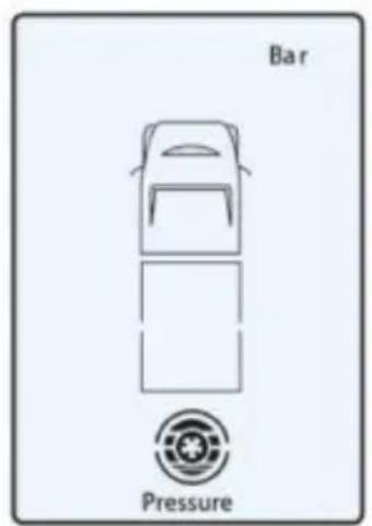
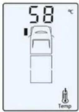
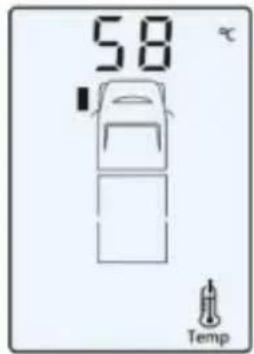
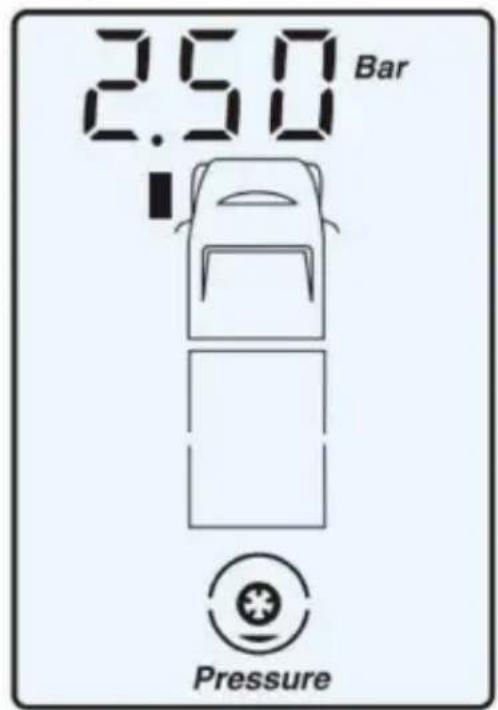
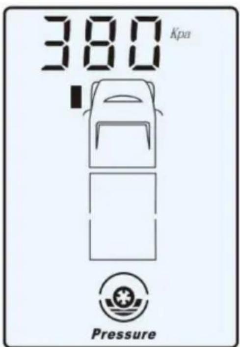
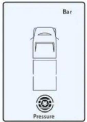
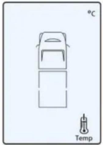
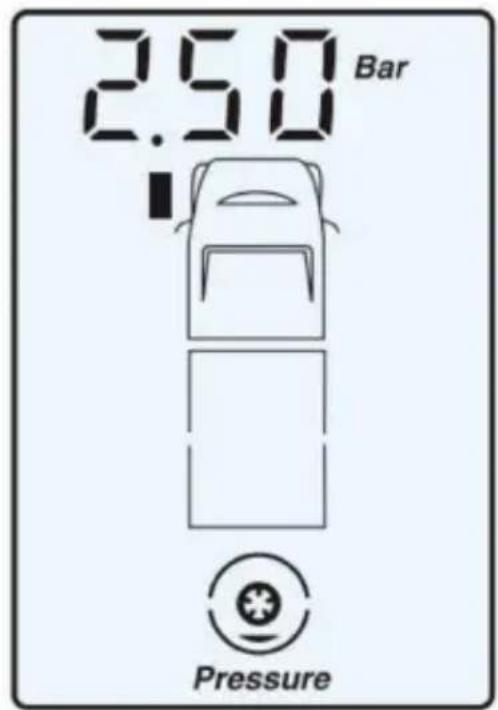
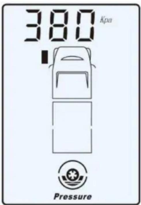
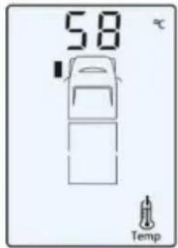
During the standby mode, press " " or " " button to check the air pressure and temperature of the designated tyre. When you press the " " button the monitor will scroll through the current pressure and temperature of each tyre, as graphics A &E below show. The indicating cycle is as follows:
» pressure of the front left tyre → » temperature of the front left tyre » pressure of the front right tyre - » temperature of the front right tyr » pressure of back left tyre → » temperature of the back left tyre » pressure of back right tyre → » temperature of the back right type → and so on.
When you press the UP button th above indicating cycle is reversed.
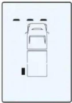
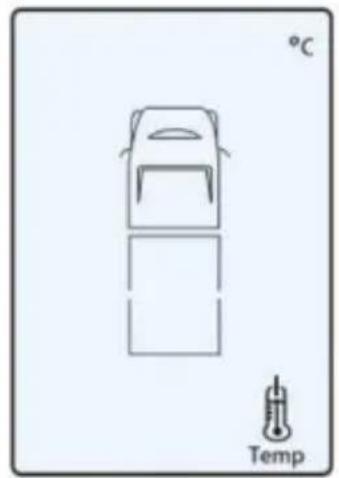
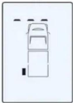
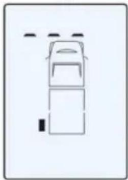
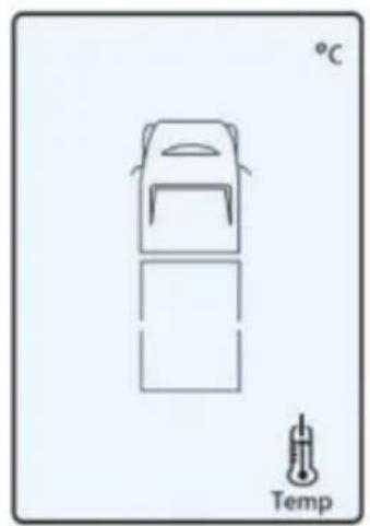
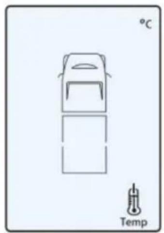
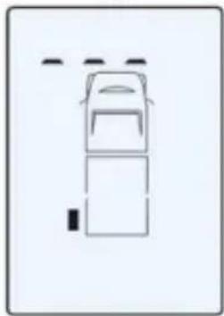
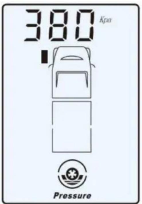
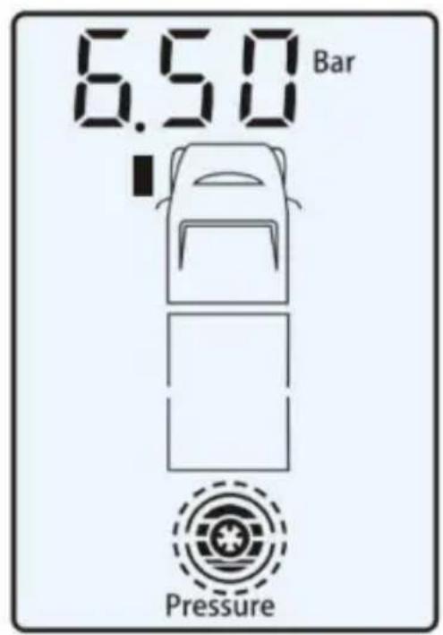
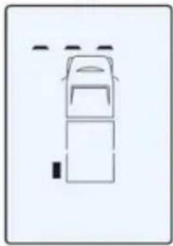
The monitor indicates “---” when a
A
B
C
D
If a specific sensor's alignment is lost from the monitor, as graphic C shows, refer to Tyre Alignment Mode on page 3 to realign the sensor.
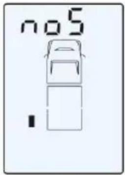
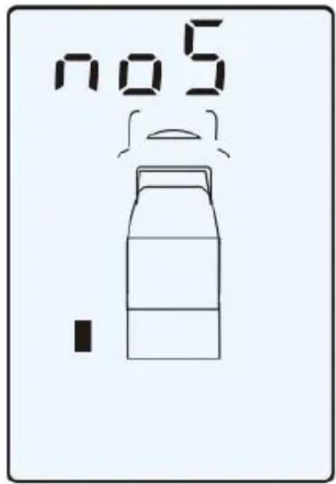
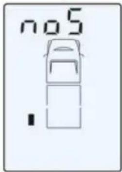
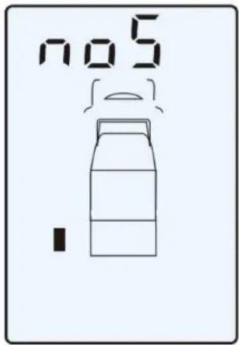
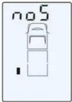
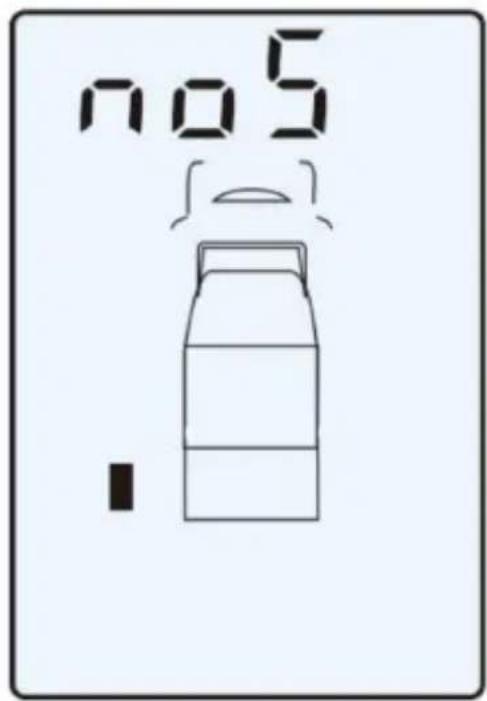
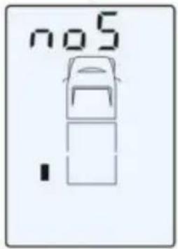
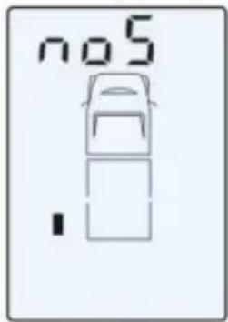
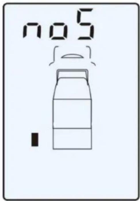
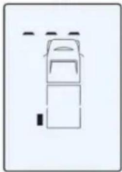
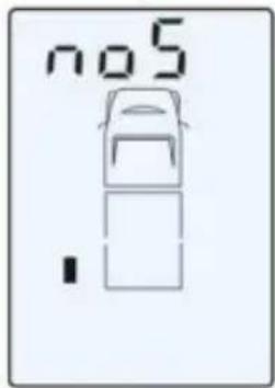
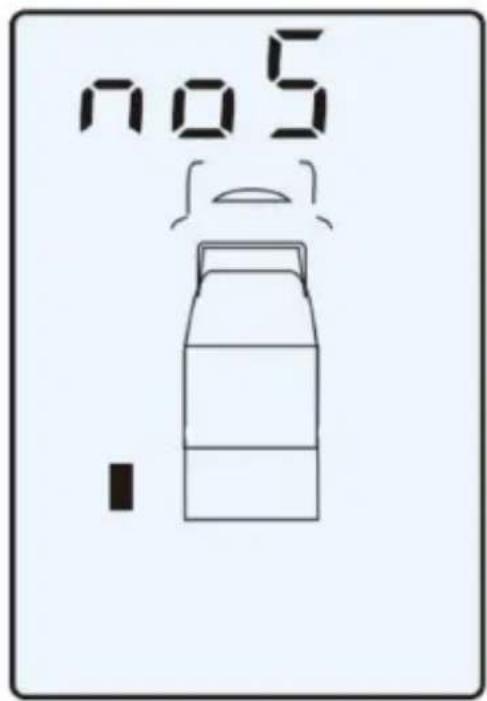
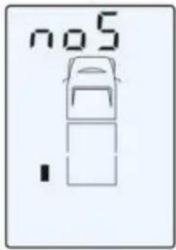
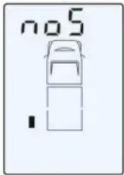
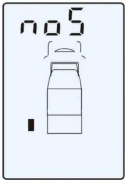
The monitor will indicate the “no S” signal whenever a sensor is either out of range or may be faulty, as graphic D shows.
Battery Capacity Indicator of the Monitor and Sensor
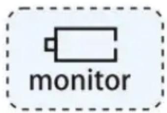
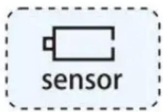
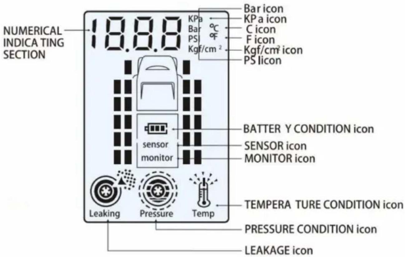
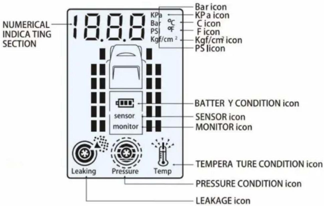
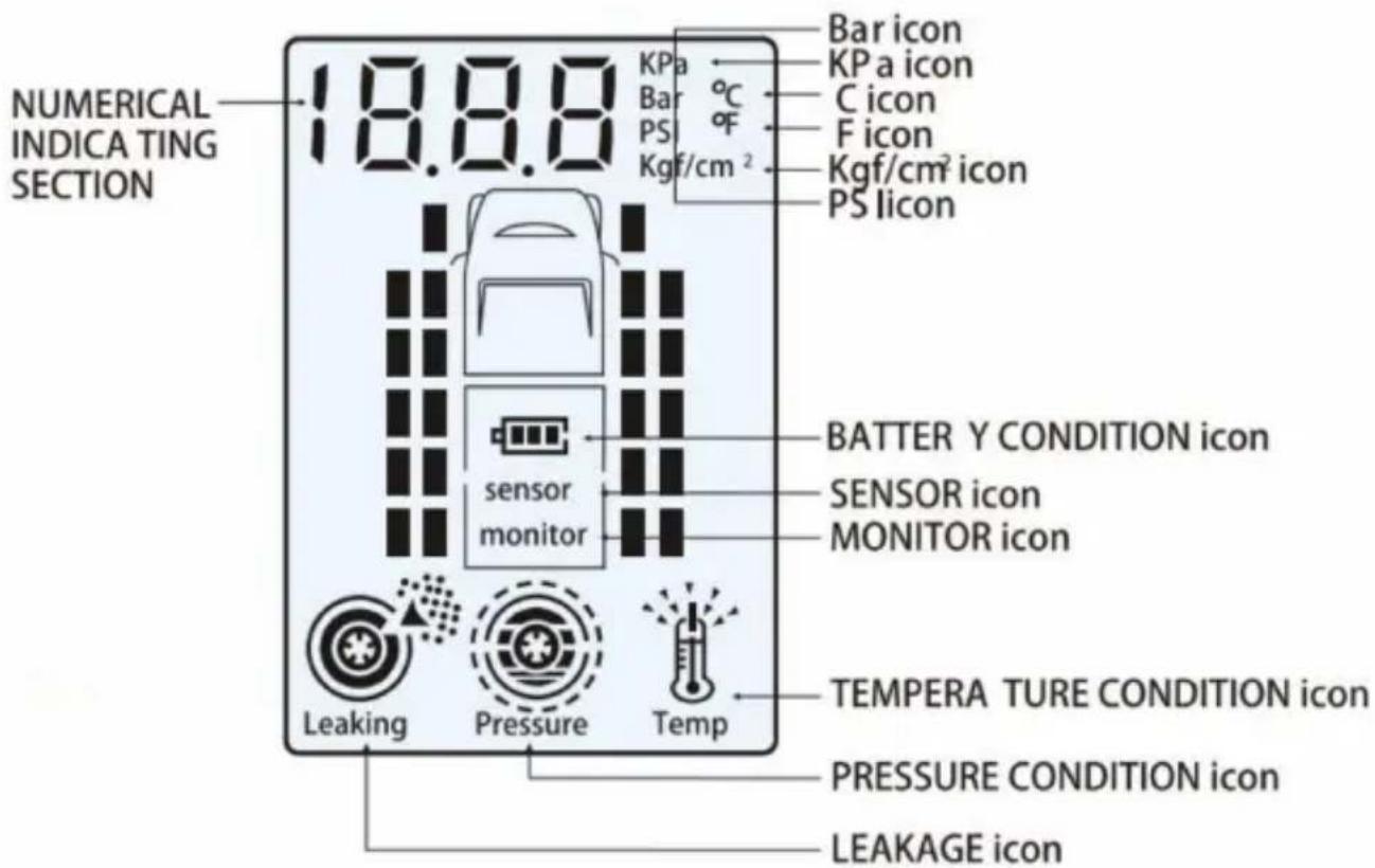
When the monitor is low on power, the battery icon and "MONITOR" icon on the screen flash, and the buzzer gives a 10-second intermittent alarm. The monitor then sounds every 30 seconds within 5 minutes of total discharge. When a tyre sensor has low power, the battery icon and "SENSOR" icon together with the corresponding tyre icon flash on the screen, and a 10-second intermittent alarm will sound. If the power of any of the sensors becomes too low, please replace the corresponding battery immediately.
Charging the Monitor
The built-in lithium battery of the monitor is rechargeable.
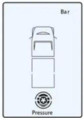
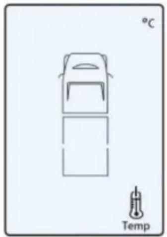
Please connect the 12/24V DC charger into the port at the base of the monitor, and then insert the adapter plug into the port of the vehicle's 12/24V DC accessory port. The vehicle's battery power will charge the monitor when the power supply of the vehicle is turned on. It takes approximately 6 hours to fully charge the monitor. The battery icon flashes as shown in graphic A, B, and
C. The monitor will sound an alarm when fully charged. Graphic C will disappear after 1 second.
Note: Please keep the monitor in a cool environment when charging.
A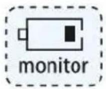
B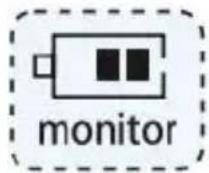
C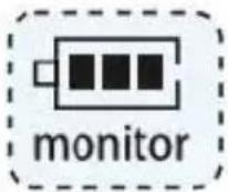
Sensor battery replacement
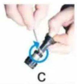
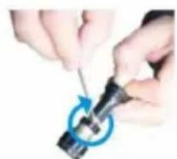
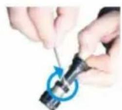
Replace the corresponding sensor's battery when the monitor indicates a low battery. Unscrew the plastic cap from the sensor, take out the battery, and replace it with a new button cell battery (CR1632). Ensure the "+" terminal is touching the upper bracket. Screw down the cover. Please refer to the right graphic A, B, and C.
Note:
- The battery model required for the sensors is a CR1632 button battery.
- The "+" and "-" poles of the sensor battery must be placed in the correct position with the "+" terminal facing up; failure to do so may cause the sensor to burn out.

- In order to make sure that the battery is replaced correctly, enter tire alignment mode and delete the alignment of the respective sensor and realign it again.
Power up
Quickly press the SET button to enter standby mode from the power-off state.
Note: Once the monitor is turned on, the information from all tires can take up to 4 minutes to be received under normal conditions. When the sensors are in an area of strong interference or in very cold conditions, the monitor may not receive the signal. Pull out the monitor's antenna to increase the strength of the signal.
Power off
Hold down the SET button for at least 8 seconds, and the monitor will automatically switch off. Please note: the system will first enter into the setting mode 5 seconds after holding down SET
button, continue holding down the SET button for a further 3 seconds or more to power off the monitor.
Note: Whether the monitor is turned on or off, the sensor is always in standby mode.
Standby Time
The monitor is installed with an intelligent 15-minute suspension device. The monitor turns into suspension status to save power after the vehicle is switched off for more than 15 minutes. Once the vehicle is started, the monitor automatically turns on and connects to the vehicle's sensors.
4. Warning Conditions
The TPMS has two functions: monitoring the tyre temperature and air pressure conditions of the vehicle's tyres.
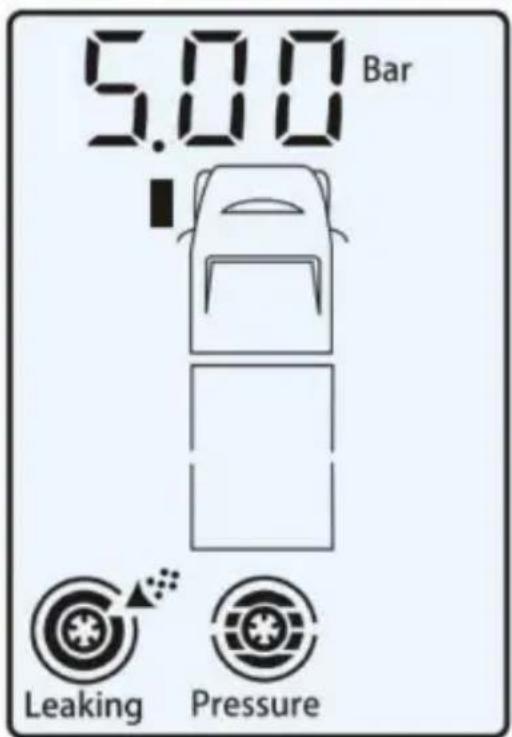
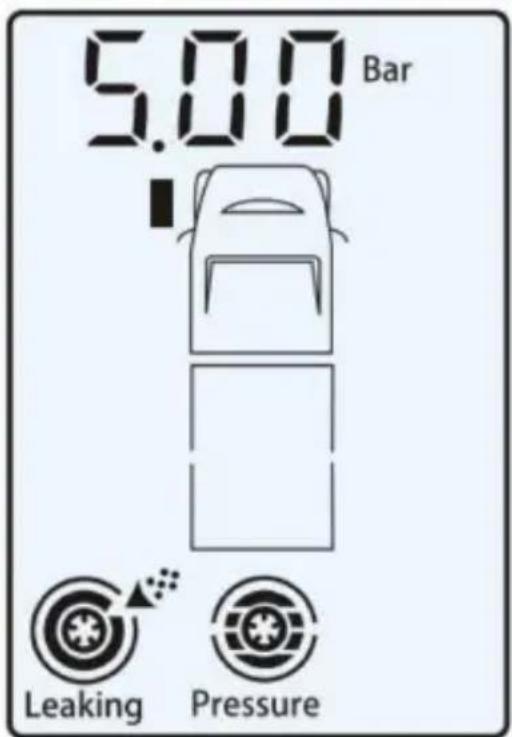
Rapid Leakage
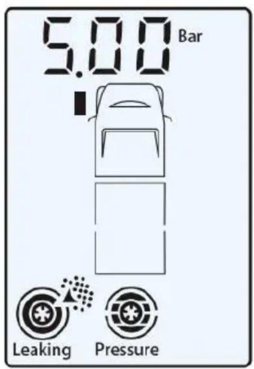
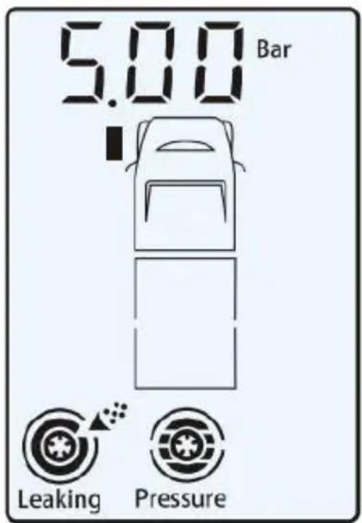
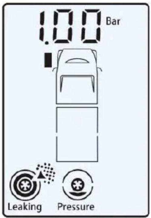
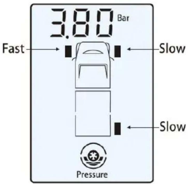
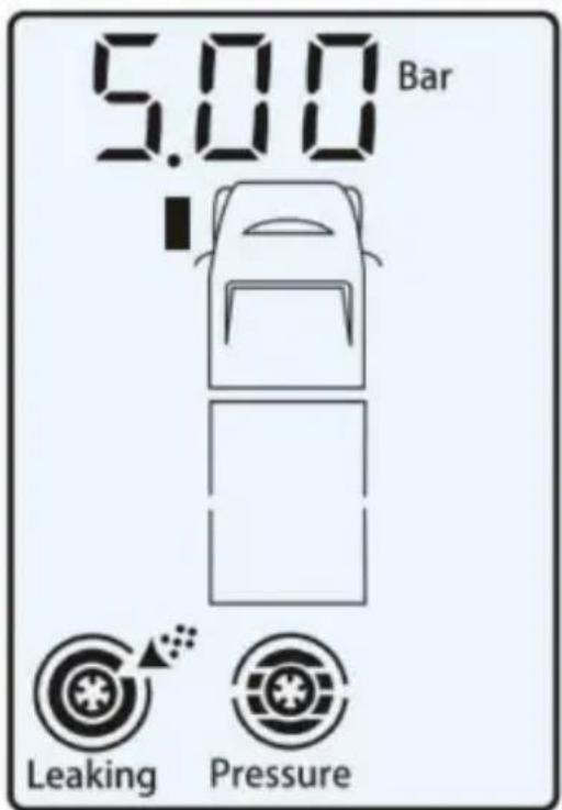
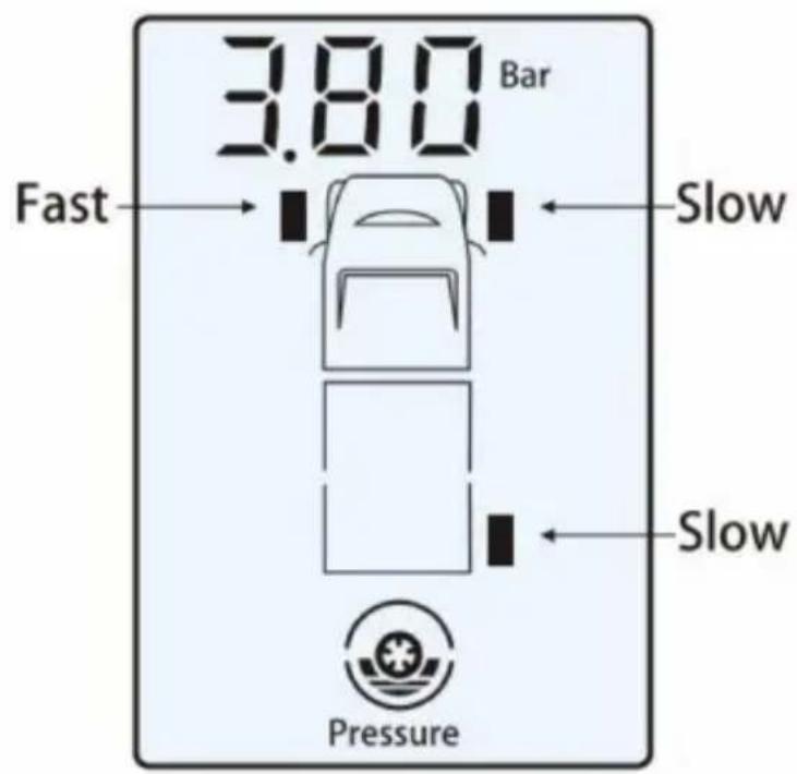
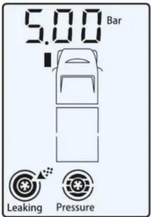
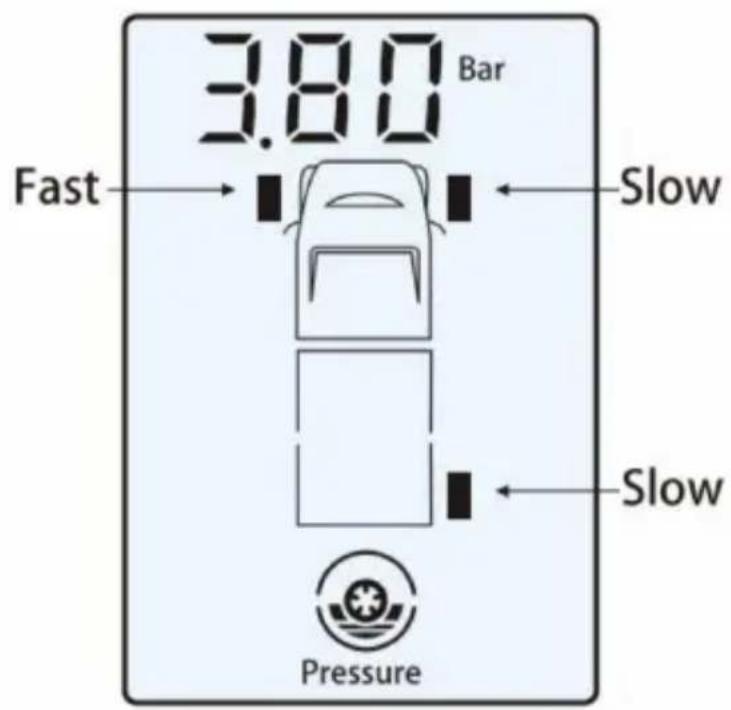
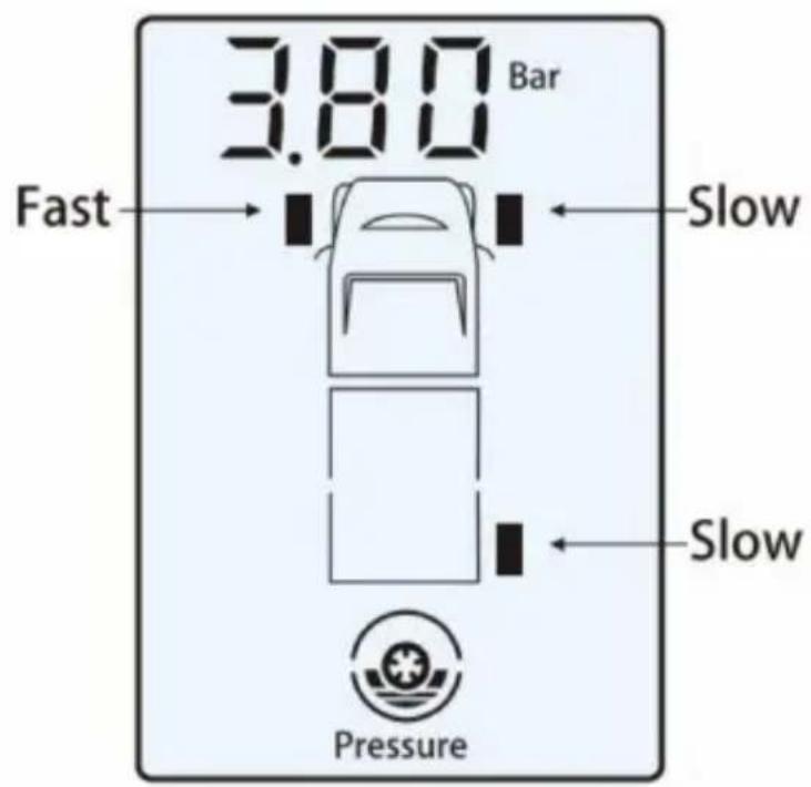
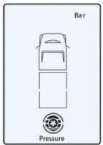
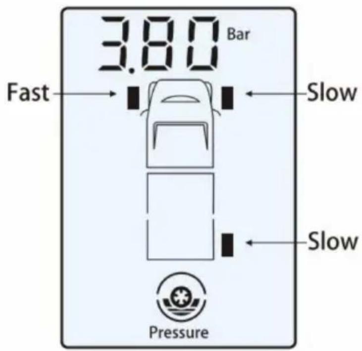
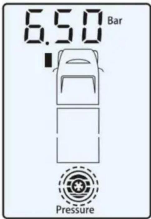
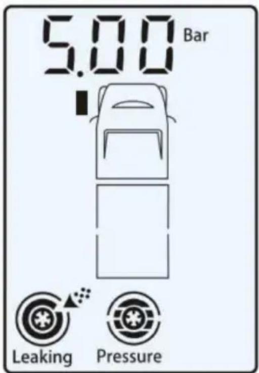
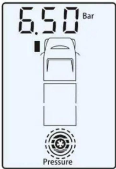
When the air pressure of a tyre drops more than 0.4 Bar (6psi) within 2 minutes, the monitor will give an alarm and the corresponding icon will flash on the monitor's screen to indicate which tyre has the abnormal air pressure and its current air pressure. The air pressure icon will flash along with the flashing red LED on the monitor, as shown in the graphic on the right.
Slow Leakage
When the air pressure of a tyre drops more than 0.4 Bar (6psi) within 2 to 10 minutes, the monitor will give an alarm and the corresponding icon will flash on the monitor's screen to indicate which tyre has the abnormal air pressure and its current air pressure. The air pressure icon will flash along with the flashing red LED on the monitor, as shown in the graphic on the right.
Note: Whether there is a fast or slow leak, the sensor will send a message to the monitor while driving or stationary.
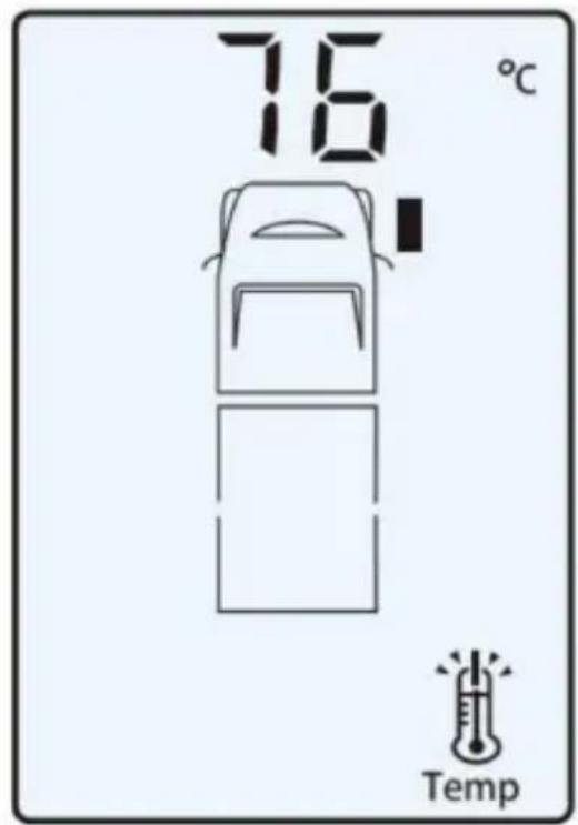
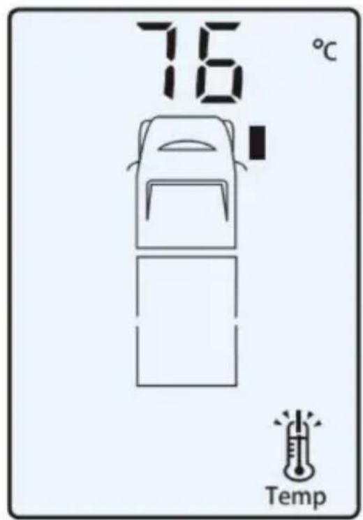
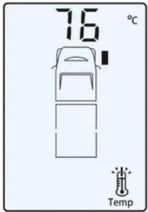
High Temperature Warning: Level 1
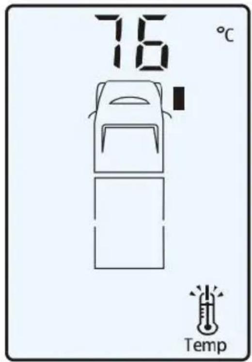
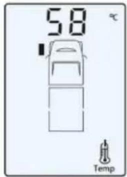
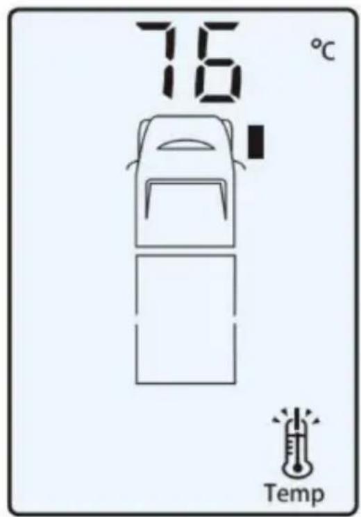
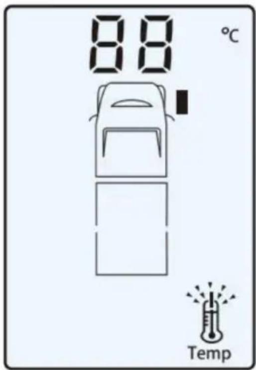
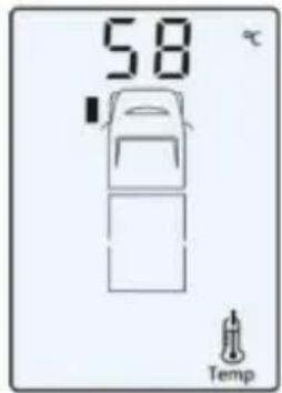
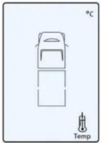
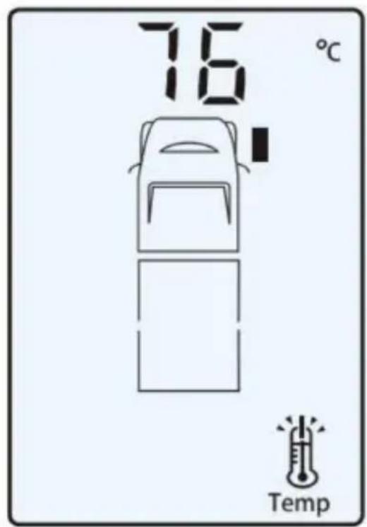
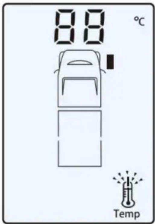
When the temperature inside the tyre exceeds 75°C, the system will give a class 1 high temperature alarm and the monitor will indicate the position of the tyre with abnormal temperature and its current temperature. Abnormal temperature is indicated by the flashing red LED on the monitor and the temperature icon flashing on the screen, as shown in the graphic on the right.
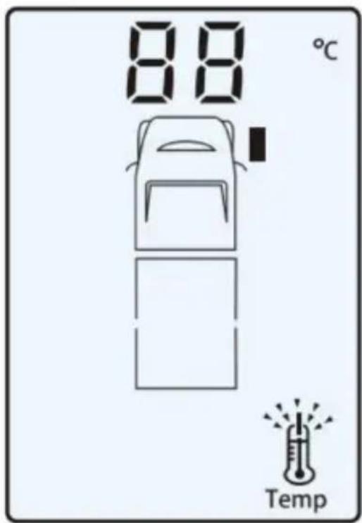
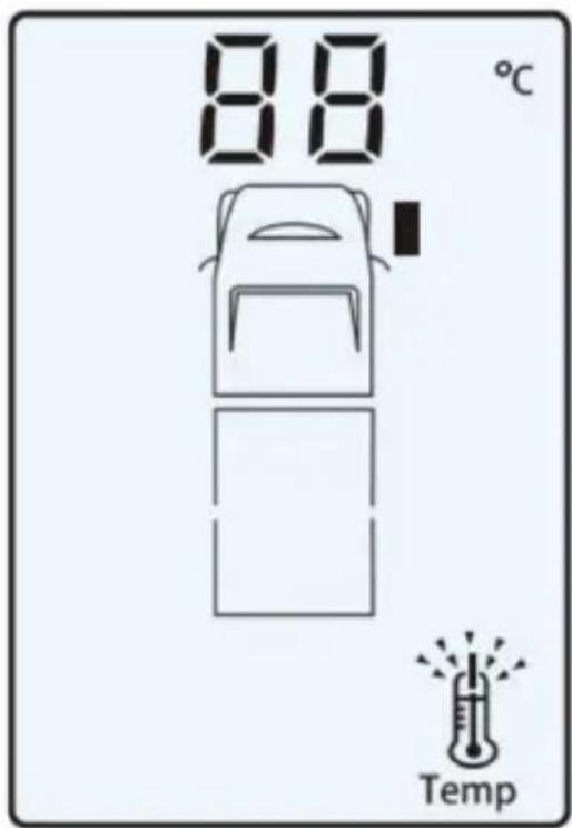
High Temperature Warning: Level 2
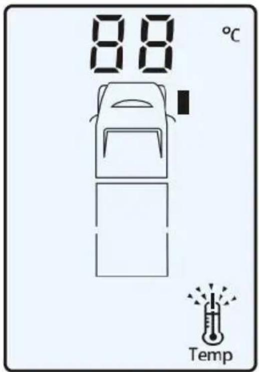
When the temperature inside the tyre exceeds 85°C, the system will give a class 2 high temperature alarm and the monitor will indicate the position of the tyre with abnormal temperature and its current temperature. Abnormal temperature is indicated by
the flashing red LED on the monitor and the temperature icon flashing on the screen, as shown in the graphic on the right.
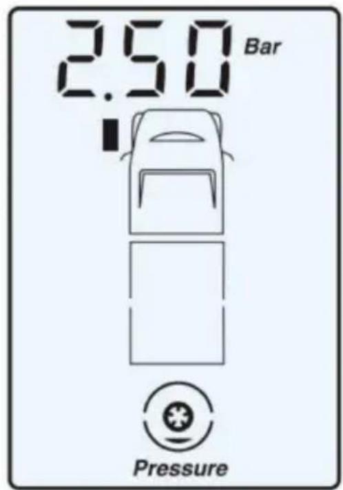
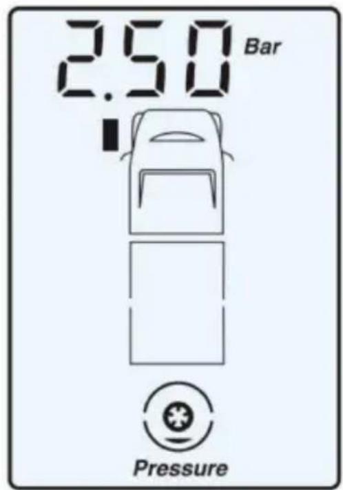
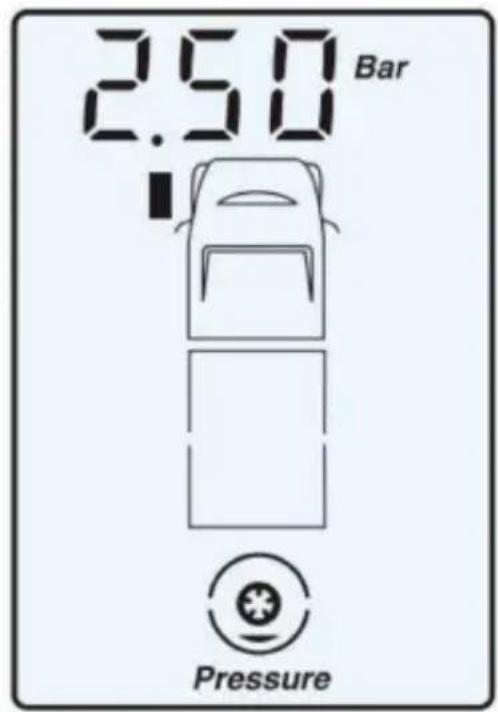
Low Air Pressure Warning: Level 1
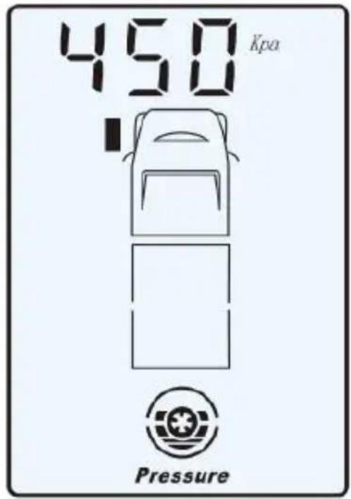
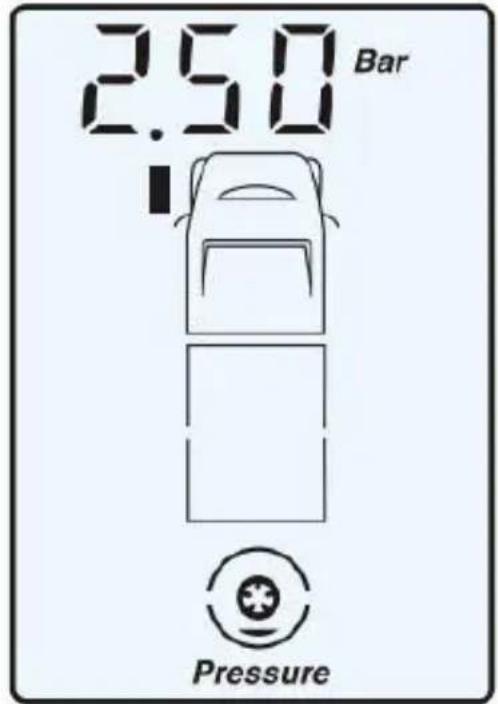
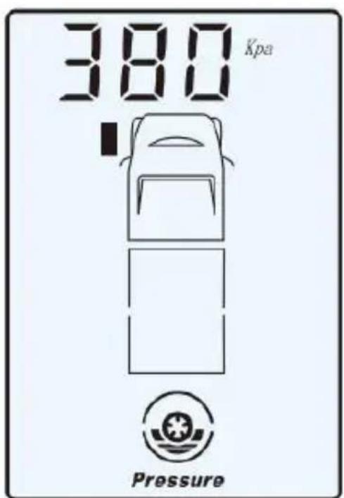
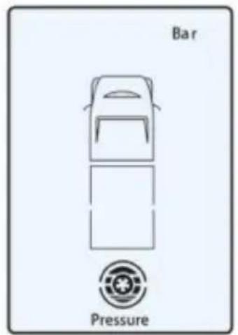
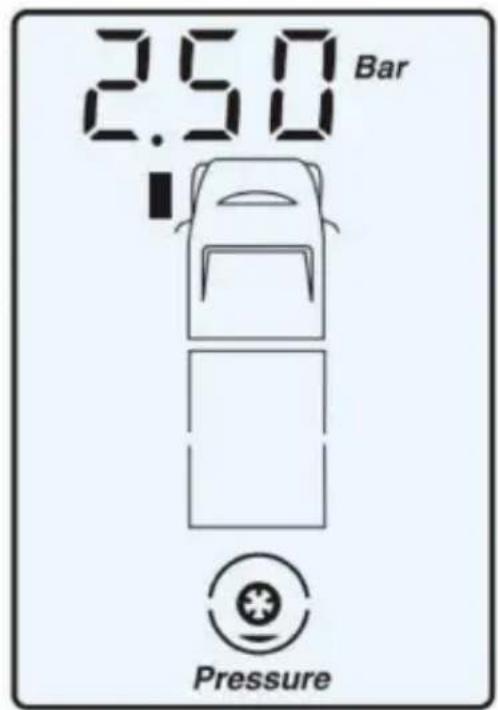
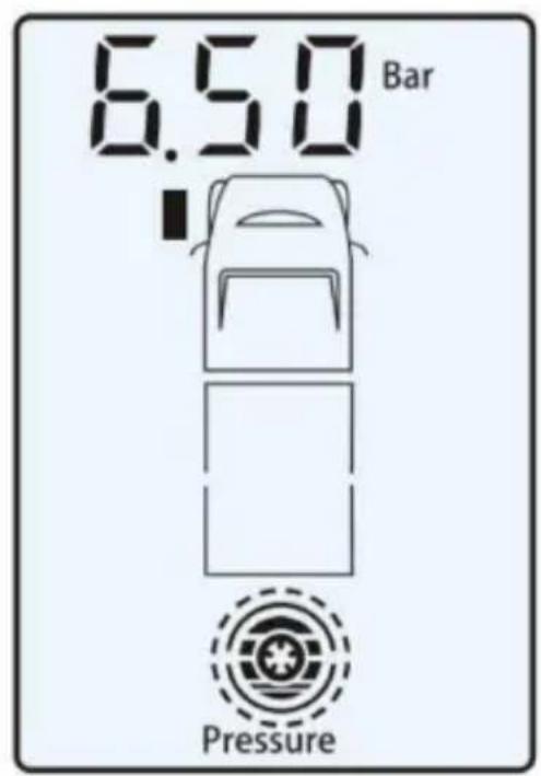
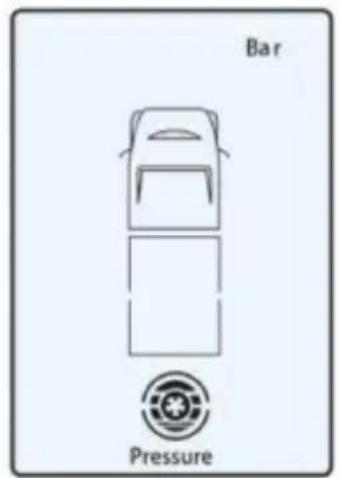
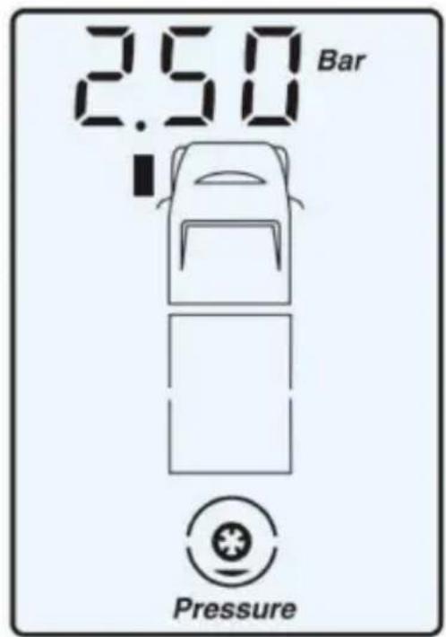
When the actual air pressure is equal to or falls below 85% of the set pressure, the system will give an alarm and the monitor will indicate the position of the tyre with abnormal air pressure and its current air pressure. The low air pressure is indicated by the flashing red LED on the monitor and the pressure icon flashing on the screen, as shown in the graphic on the right.
Low Air Pressure Warning: Level 2
When the actual air pressure is equal to or falls below 75% of the set pressure, the system will give an alarm and the monitor will indicate the position of the tyre with abnormal air pressure and its current air pressure. The low air pressure is indicated by the flashing red LED on the monitor and the pressure icon flashing on the screen, as the right graphic shows.
Low Air Pressure Warning: Level 3
When the actual air pressure is equal to or falls below 50% of the set pressure, the system will give an alarm and the monitor will indicate the position of the tyre with abnormal air pressure and its current air pressure. The low air pressure is indicated by the flashing red LED on the monitor and the pressure icon flashing on the screen, as the right graphic shows.
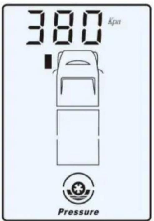
High Air Pressure Warning
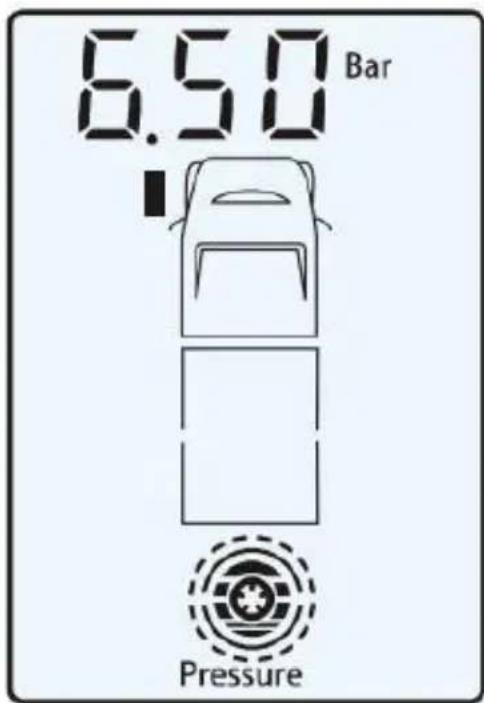
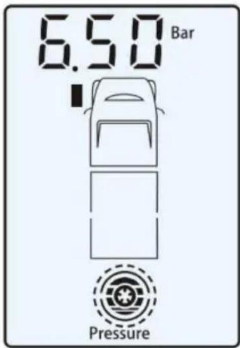
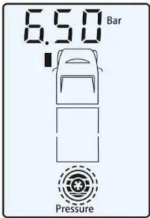
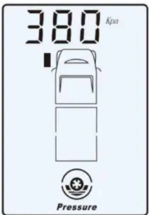
When the actual air pressure is equal to or greater than 120% of the set pressure, the system will give an alarm and the monitor will indicate the position of the tyre with abnormal air pressure and its current air pressure. The high air pressure is indicated by the flashing red LED on the monitor and the pressure icon flashing on the screen, as the right graphic shows.
Multi-Warning Indication
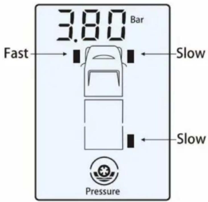
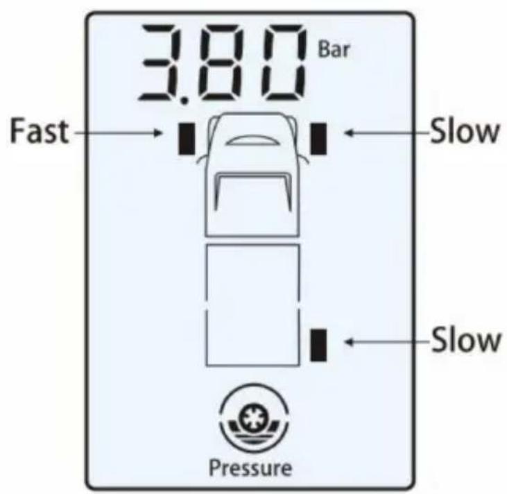
- When one tyre has numerous abnormalities at once, the monitor will indicate all the various abnormalities as the graphic at right shows.
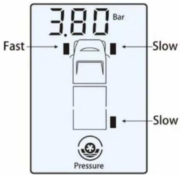
- When there are abnormalities with two or more tyres at the same time, the respective tyre icons with the abnormalities will flash on the screen. Further, the current tyre reading being displayed, its tyre icon will flash more rapidly than the other icons, as the right graphic shows.
Sensor Abnormality Indication
If the monitor can't receive the signal from the sensors within 20 minutes in standby mode, the alarm system will sound for 15
seconds. The corresponding icon of the abnormal sensor will also flash and indicate with "no S" which indicates there is either a fault in the sensor, the sensor is damaged, or the sensor is out of range. The system will alarm every 20 minutes if the monitor still can't receive the signal from the sensor, as the graphic at right shows.
Explanation
The monitor will give out a continuous alarm for 15 seconds with the flashing red LED and back lights for 5 minutes along with the corresponding faulty tyre icon flashing. Press the " " or " " button to stop this alarm. Shortly after, the back light will automatically go off. The system alarm will sound again after one hour to further remind the operator.
When a sensor is removed to inflate or deflate a tyre, this will cause the sensor to detect rapid and/or slow leakage because the sensor has suddenly detected zero pressure. The monitor will return to normal and the alarm will stop after the sensor is refitted.
If you wish to add further sensors to the monitoring system, i.e. fitting sensors to an additional caravan or trailer, etc., refer to procedure 3, Installation & Operating Instructions.
5. Technical Specifications
Sensor
| Working Temperature | 14°F to 185°F(-10°C to 85°C) |
| Working Humidity | 0-95% |
| Dimension | 24 x 21 x 21 mm |
| Weight | 11 g (±1 g) |
| Battery Voltage | 3V DC (Cr1632) |
| Battery Life | 1 Year |
| Standby Current | 500mA |
| Working Current | 6mA |
| Pressure Measure Range | 0 psi - 232 psi(0 bar - 16 l) |
| Pressure Measure Precision | ±4.35 psi (± 0.3 bar) |
| Temperature Measure Range | 14°F to 185°F(-10°C to 85°C) |
| Temperature Measure Precision | ±3°C |
| Signal Transmitting Frequency | 433.92MHZ |
| Operating Distance | up to 65 ft (20 m) Booster recommended If towing or over 25 ft (Receiver to rear Tire) |
Monitor
| Working Voltage | 3V DC |
| Working Temperature | -4°F to 140°F(-20°C to 60°C) |
| Working Humidity | 0-90% |
| Standby Current | 0.1mA |
| Working Current Dimension | 15mA |
| Signal Receiving Frequency | 433.92MHZ |
| Color of Backlight | White |
| Dimensions | Monitor Size: 82 x 55 x 23 mm (JET-M-400C) |
TPMS Assembly
| Name | Quantity |
| Sensors/Transmitter | 6 |
| Bracket | 1 |
| wrench | 1 |
| CR 1632 Battery | 6 |
| Anti-theft Security Device | 6 |
| charger | 1 |
| host computer | 1 |
| repeater | 1 |
| stand base | 1 |
| ribbon | 4 |
NOTE:
- This system can efficiently monitor the air pressure and temperature of the vehicle's tyres.
- In order to avoid damage to this equipment, please do not attempt to disassemble any assembly.
- Your TPMS has an automatic monitoring function, so there is no need to press " or " " to read the information.
- Please contact Shenzhen Jetson Electronic Technologies Co., Ltd.
TEL: 86-755-2952496081716422
FAX:86-755-29472905
or log on to our website www.tesee.com.cn should you require further information.
6. Transmission Booster Operating Instructions 6.1 Function
The VEVOR transmission boosters function with two VEVOR brand TPMS systems for trucks. Even though the basic systems have been tested and work well up to 60 ft., there are occasions where a vehicle will emit electronic interference causing the loss of signal from the transmitters. The chance of lost signals also increases with distance (from receiver to rear tires), extreme cold and battery deterioration.
6.2 Operation
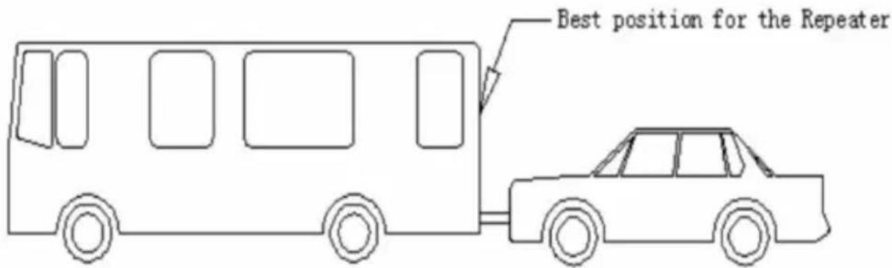
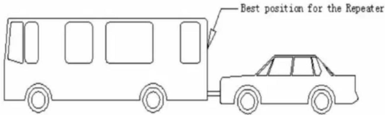
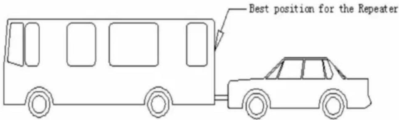
Once installed on the tow vehicle or approximate middle of a large Motor coach, no further programming or action is necessary. The VEVOR Booster will automatically pick up the
signals from all transmitters and resend the information to the receiver/monitor.
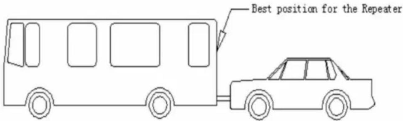
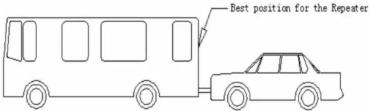
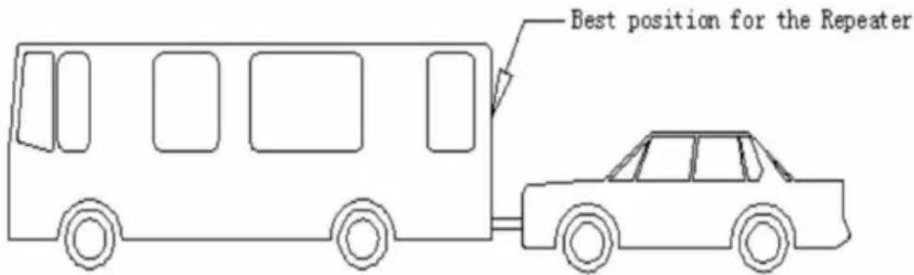
6.3 Installation Position
Although fully weather proof, it is recommended to install the booster in a relatively protected area.
The illustration below shows the ideal location for RV, Caravan, trailer and truck use.



6.4 Installation
The JET100A VEVOR booster comes with several “wire ties” which may be used to secure it and its power cord wherever. Please mount as securely as possible to minimize vibration.
6.5 Power Supply
Model JET-100A requires external DC power: DC 12V or DC 24V. Red wire is “+” positive, black wire is “-” negative. If uncertain, contact a local repair facility to help install the unit.
6.6 Technical Data:
| Working Temperature | -40 to 85°C (-40 to 185°F) |
| Working Voltage | DC 12V - 24V |
| Working Frequency | 433.92MHZ |
7. FCC Information:
CAUTION: Changes or modifications not expressly approved by the party responsible for compliance could void the user's authority to operate the equipment!
This device complies with Part 15 of the FCC Rules. Operation is subject to the following two conditions:
1) This product may cause harmful interference. 2) This product must accept any interference received, including interference that may cause undesired operation.
WARNING: Changes or modifications to this product not expressly approved by the party responsible for compliance could void the user's authority to operate the product.
Note: This product has been tested and found to comply with the limits for a Class B digital device pursuant to Part 15 of the FCC Rules. These limits are designed to provide reasonable protection against harmful interference in a residential installation.
This product generates, uses, and can radiate radio frequency energy, and if not installed and used in accordance with the instructions, may cause harmful interference to radio communications.
However, there is no guarantee that interference will not occur in a particular installation. If this product does cause harmful interference to radio or television reception, which can be determined by turning the product off and on, the user is encouraged to try to correct the interference by one or more of the following measures.
• Reorient or relocate the receiving antenna. • Increase the distance between the product and receiver. • Connect the product to an outlet on a circuit different from that to which the receiver is connected. • Consult the dealer or an experienced radio/TV technician for assistance.
8. CORRECT DISPOSAL

This product is subject to the provisions of European Directive 2012/19/EU. The symbol showing a wheelie bin crossed through indicates that the product requires separate refuse collection in the European Union. This
applies to the product and all accessories marked with this symbol. Products marked as such may not be discarded with normal domestic waste, but must be taken to a collection point for recycling electrical and electronic devices.
Manufacturer: Shanghai Muxin Muye Youxian Gongsi
Address: Shuangcheng Road 803 Nong 11 Hao 1602A-1609 Shi, Baoshan District, Shanghai 200000 CN.
Imported to AUS: SIHAO PTY LTD. 1 ROKEVA
STREET EASTWOOD NSW 2122 Australia
Imported to USA: Sanven Technology Ltd. Suite 250, 9166
Anaheim Place, Rancho Cucamonga, CA 91730
| UK | REP |
YH CONSULTING LIMITED.
C/O YH Consulting Limited Office 147, Centurion House, London Road,
Staines-upon-Thames, Surrey, TW18 4AX
| EC | REP |
E-CrossStu GmbH
Mainzer Landstr.69,
60329 Frankfurt am Main.
VEVOR®
TOUGH TOOLS, HALF PRICE
Technical Support and E-Warranty Certificate
www.vevor.com/support
VEVOR®
TOUGH TOOLS, HALF PRICE
www.vevor.com/support
SOLAR TPMS
MODEL: M400C
NEED HELP? CONTACT US!
SENSOR
2. Function La
JET-M-400C (MONITOR)
A
B
C
A
B
C
D
| Name | Quantity |
| Sensors/Transmitter | 6 |
| Bracket | 1 |
| wrench | 1 |
| CR 1632 Battery | 6 |
| Anti-theft Security Device | 6 |
| charger | 1 |
| host computer | 1 |
| repeater | 1 |
| stand base | 1 |
| ribbon | 4 |
NOTE:

6.4 Installation
C/O YH Consulting Limited Bureau 147, Maison Centurion, London Road,
Staines-upon-Thames, Surrey, TW18 4AX
E-CrossStu GmbH
Mainzer Landstr. 69,
SENSOR
2. Function The
JET-M-400C (MONITOR)
Unit conversion
Note:
Installation of the monitor
A
B
C
A
B
C
D
| Name | Quantity |
| Sensors/Transmitter | 6 |
| Bracket | 1 |
| wrench | 1 |
| CR 1632 Battery | 6 |
| Anti-theft Security Device | 6 |
| charger | 1 |
| host computer | 1 |
| repeater | 1 |
| stand base | 1 |
| ribbon | 4 |
NOTE:


6.4 Installation
Anaheim Place, Rancho Cucamonga, CA 91730
| UK REP |
YH CONSULTING LIMITED.
C/O YH Consulting Limited Office 147,
Centurion House, London Road,
Staines-upon-Thames, Surrey, TW18 4AX
www.vevor.com/support
VEVOR®
TOUGH TOOLS, HALF PRICE
www.vevor.com/support
TPMS SOLARE
MODELLO: M400C
SENSOR
2. Function The
JET-M-400C (MONITOR)
Conversion of the
B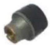
C
Note:
A
B
C
A
B
C
D


| Name | Quantity |
| Sensors/Transmitter | 6 |
| Bracket | 1 |
| wrench | 1 |
| CR 1632 Battery | 6 |
| Anti-theft Security Device | 6 |
| charger | 1 |
| host computer | 1 |
| repeater | 1 |
| stand base | 1 |
| ribbon | 4 |
NOTE:

6.4 Installation
Imported in AUS: SIHAO PTY LTD. 1 ROKEVA STREET EASTWOOD NSW 2122 Australia
C/O YH Consulting Limited Ufficio 147,
Casa del Centurione, London Road,
Staines-upon-Thames, Surrey, TW18 4AX
| REP.CE |
E-CrossStu GmbH
Mainzer Landstr.69,
www.vevor.com/support
SOLAR TPMS
MODEL: M400C
SENSOR
JET-M-400C (MONITOR)
Conversion of
B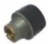
C
Note:
A
B
C
A
B
C
D
| Name | Quantity |
| Sensors/Transmitter | 6 |
| Bracket | 1 |
| wrench | 1 |
| CR 1632 Battery | 6 |
| Anti-theft Security Device | 6 |
| charger | 1 |
| host computer | 1 |
| repeater | 1 |
| stand base | 1 |
| ribbon | 4 |
NOTE:

6.4 Installation
The VEVOR JET100A amplifier comes with several "cable ties"
Anaheim Place, Rancho Cucamonga, CA 91730
YH CONSULTING LIMITED.
C/O YH Consulting Limited Office 147, Centurion House, London Road,
Staines upon Thames, Surrey, TW18 4AX
E-CrossStu GmbH
Mainzer Landstr.69,
NEED HELP? CONTACT US!
SENSOR
2. Function Function
JET-M-400C (MONITOR)
Unit conversion
Monitor installation
A
B
C
A
B
C
D
| Name | Quantity |
| Sensors/Transmitter | 6 |
| Bracket | 1 |
| wrench | 1 |
| CR 1632 Battery | 6 |
| Anti-theft Security Device | 6 |
| charger | 1 |
| host computer | 1 |
| repeater | 1 |
| stand base | 1 |
| ribbon | 4 |
NOTE:

6.4 Installation
STREET EASTWOOD NSW 2122 Australia
Imported from USA: Sanven Technology Ltd. Suite 250, 9166
Anaheim Place, Rancho Cucamonga, California 91730
C/O YH Consulting Limited Office 147,
Centurion House, London Road,
Staines-upon-Thames, Surrey, TW18 4AX
| REPREZENT KE |
E-CrossStu GmbH
Mainzer Landstr. 69,
60329 Frankfurt am Main.
VEVOR®
TOUGH TOOLS, HALF PRICE
www.vevor.com/support
VEVOR®
TOUGH TOOLS, HALF PRICE
www.vevor.com/support
ZONNE-TPMS
MODEL: M400C
NEED HELP? CONTACT US!
SENSOR
JET-M-400C (MONITOR)
Unit Conversion
Note:
A
B
C
A

B
C
D

| Name | Quantity |
| Sensors/Transmitter | 6 |
| Bracket | 1 |
| wrench | 1 |
| CR 1632 Battery | 6 |
| Anti-theft Security Device | 6 |
| charger | 1 |
| host computer | 1 |
| repeater | 1 |
| stand base | 1 |
| ribbon | 4 |
NOTE:

6.4 Installation
Anaheim Place, Rancho Cucamonga, CA 91730
YH CONSULTING LIMITED.
C/O YH Consulting Limited Office 147, Centurion House, London Road,
Staines-upon-Thames, Surrey, TW18 4AX
E-CrossStu GmbH
Mainzer Landstr.69,
60329 Frankfurt am Main.
VEVOR®
TOUGH TOOLS, HALF PRICE
Technical support and e-warranty certificate www.vevor.com/support
VEVOR®
TOUGH TOOLS, HALF PRICE
www.vevor.com/support
SOLAR TPMS
MODEL: M400C
NEED HELP? CONTACT US!
SENSOR
2. Function
JET-M-400C (MONITOR)
Units Conversion
Temperature Units Conversion F=9C/
5+32 Note: C=Celsius; F=Fahrenheit Pressure Units
Conversion 1 bar=14.5 psi
1 bar=100 kPa
1 bar=1.02 kgf/cm2
A
B
C
A
B
C
D
Multiple warning indication
| Name | Quantity |
| Sensors/Transmitter | 6 |
| Bracket | 1 |
| wrench | 1 |
| CR 1632 Battery | 6 |
| Anti-theft Security Device | 6 |
| charger | 1 |
| host computer | 1 |
| repeater | 1 |
| stand base | 1 |
| ribbon | 4 |
NOTE:

6.4 Installation
The JET100A VEVOR booster comes with several "cable ties"
7. FCC information: WARNING:
Anaheim Place, Rancho Cucamonga, CA 91730
| UK | REP |
YH CONSULTING LIMITED.
C/O YH Consulting Limited Office 147,
Centurion House, London Road,
Staines-upon-Thames, Surrey, TW18 4AX

E-CrossStu GmbH
Mainzer Landstr.69,
60329 Frankfurt am Main.
VEVOR®
TOUGH TOOLS, HALF PRICE
www.vevor.com/support
- SOLAR TPMS
- MODEL: M400C
- VEVOR®
- NEED HELP? CONTACT US
- INSTRUCTION
- FUNCTION
- THE FOLLOWING INSTRUCTIONS SHOW THE IDENTIFICATION OF OPERATING BUTTONS OF THE MONITOR
- TEMPERATURE UNITS CONVERSION
- F=9C/5+32 NOTE: C=CELSIUS; F=FAHRENHEIT
- BAR=14.5 PSI 1 BAR=100 KPA 1 BAR=1.02 KGF/CM²
- INSTALLATION OF THE SENSOR AND ANTI-THEFT DEVICE
- NOTE
- INSTALLATION OF THE MONITOR
- STANDARD PRESSURE SETTING
- EXAMINATION OF THE TYRE CONDITION
- BATTERY CAPACITY INDICATOR OF THE MONITOR AND SENSOR
- CHARGING THE MONITOR
- SENSOR BATTERY REPLACEMENT
- POWER UP
- POWER OFF
- STANDBY TIME
- WARNING CONDITIONS
- RAPID LEAKAGE
- SLOW LEAKAGE
- HIGH TEMPERATURE WARNING: LEVEL
- LOW AIR PRESSURE WARNING: LEVEL
- HIGH AIR PRESSURE WARNING
- MULTI-WARNING INDICATION
- SENSOR ABNORMALITY INDICATION
- EXPLANATION
- TECHNICAL SPECIFICATIONS
- TRANSMISSION BOOSTER OPERATING INSTRUCTIONS 6.1 FUNCTION
- OPERATION
- INSTALLATION POSITION
- INSTALLATION
- POWER SUPPLY
- TECHNICAL DATA
- FCC INFORMATION
- CORRECT DISPOSAL
- TOUGH TOOLS, HALF PRICE
- SENSOR
- FUNCTION LA
- FUNCTION THE
- UNIT CONVERSION
- TPMS SOLARE
- MODELLO: M400C
- CONVERSION OF THE
- FUNCTION FUNCTION
- MONITOR INSTALLATION
- ZONNE-TPMS
- UNITS CONVERSION
- MULTIPLE WARNING INDICATION
- FCC INFORMATION: WARNING
Brand : Vevor
Model : M400C
Category : Measuring equipment