TS552 - Measuring equipment Vevor - Free user manual and instructions
Find the device manual for free TS552 Vevor in PDF.

| Product Type | Cable Locator |
| Brand | Vevor |
| Model | TS552 |
| Composition | Transmitter and receiver |
| Output frequency (transmitter) | 125 kHz |
| Voltage measurement range (transmitter) | 12 V to 600 V DC/AC (50-60 Hz) |
| Tracing depth (unipolar) | Up to 2 m |
| Tracing depth (bipolar) | Up to 0.5 m (up to 2.5 m with separate return line) |
| Non-contact voltage detection | 90 V to 264 V AC, 50-60 Hz |
| Power supply | 2 x 9 V batteries (type 6F22 or equivalent) |
| Transmitter dimensions | 133 x 76 x 32 mm |
| Transmitter weight | Approx. 207 g (with battery) |
| Receiver dimensions | 186 x 60 x 35 mm |
| Receiver weight | Approx. 234 g (with battery) |
| Measurement category | CAT III 600 V |
| Protection rating | IP20 |
| Operating temperature | 0 °C to 40 °C |
| Storage temperature | -20 °C to 60 °C |
| Display | LCD with backlight |
| Included accessories | 2 test leads, 2 probes, 2 alligator clips, 1 ground stake, 1 carrying bag, 1 manual |
| Maintenance | Clean with a damp cloth; replace batteries if low battery indicator appears |
| Fuse replacement (transmitter) | 500 mA/600 V, fast-acting, 6.35 x 32 mm |
| Recommended calibration | Every year (or every 3 years for infrequent use) |
| Warranty | Technical support and electronic warranty certificate at www.vevor.com/support |
Frequently Asked Questions - TS552 Vevor
User questions about TS552 Vevor
0 question about this device. Answer the ones you know or ask your own.
Ask a new question about this device
Download the instructions for your Measuring equipment in PDF format for free! Find your manual TS552 - Vevor and take your electronic device back in hand. On this page are published all the documents necessary for the use of your device. TS552 by Vevor.
USER MANUAL TS552 Vevor
Technical Support and E-Warranty Certificate
www.vevor.com/support
CABLE LOCATOR
MODEL:TS552
We continue to be committed to provide you tools with competitive price. "Save Half", "Half Price" or any other similar expressions used by us only represent estimate of savings you might benefit from buying certain tools with us compared top brands and does not necessarily mean to cover all categories of tools offered are kindly reminded to verify carefully when you are placing an order with us actually saving half in comparison with the top major brands.
MODEL:TS552
NEED HELP? CONTACT US!
Have product questions? Need technical support? Please feel fr contact us:
Technical Support and E-Warranty Certificate www.vevor.com/support
This is the original instruction, please read all manual instructions carefully before operating. VEVOR reserves a clear interpretation of user manual. The appearance of the product shall be subject to product you received. Please forgive us that we won't inform your use, there are any technology or software updates on our product.
 | Warning-To reduce the risk of injury, user must read instructi manual carefully. |
 | This device complies with Part 15 of the FCC Rules. Operat subject to the following two conditions:(1)This device may not harmful interference, and (2)this device must accept any inter received, including interference that may cause undesired oper |
 | This product is subject to the provision of European Directive 2012/19/EC. The symbol showing a wheelie bin crossed throu indicates that the product requires separate refuse collection i European Union. This applies to the product and all accesso marked with this symbol. Products marked as such may not discarded with normal domestic waste, but must be taken to collection point for recycling electrical and electronic devices |
INTRODUCTION
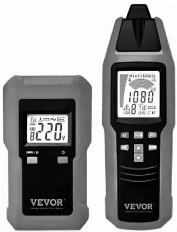
This cable locator is a portable instrument designed to detect or trace condu It consists of a transmitter and a receiver. The signal generated by the trans is a modulated current which generates an electromagnetic field around the conductor connected. This electromagnetic field induces a voltage within the receiving coil of the receiver. Then the induced voltage is amplified, decoded, converted by the receiver, and finally indicated on the receiver screen.
Features:
● Finding cable in wall, line interruption, or short-circuit in a line.
● Tracing a cable that is in soil.
- Detecting fuse or circuit breaker and assigning current circuits.
- Tracing socket or distribution socket that has accidentally been covered by plastering.
- Detecting interruption or short-circuit in floor heating.
● Tracing metallic water and heating piping.
● Various applications in both voltage-free and live systems.
- The screen of the transmitter indicates the transmission level, the transmission code, and the foreign voltage.
- The screen of the receiver indicates the reception level and the transmission code.
● Mains voltage detection by using the receiver.
● Automatic and manual sensitivity adjustment of the receiver.
● Acoustic signal indication of the receiver may be turned off. - Illumination function.
● Automatic power-off. - Backlight.
Supply list:
- One transmitter.
- One receiver.
- Two test leads.
- Two test leads that have a probe.
- Two alligator clips.
- 1 ground stake.
- One carrying bag.
- One manual.
SAFETY INFORMATION
- Adhere to local and national safety codes. Individual protective equipment must be used to prevent shock and arc blast injury where hazardous live conductors are exposed.
- Do not operate the instrument where explosive (or combustible) gas, vapor or dust is present.
- Use caution when working with voltage above 30V ac rms, 42V peak, or dc. Such voltages pose a shock hazard.
- To avoid electric shock, do not touch any naked conductor with hand or s and do not ground yourself while using the instrument.
- Do not use the instrument if it is damaged or operates abnormally.
- Inspect the test leads for damaged insulation or exposed metal. If a test is damaged, replace it with a new one of the same ratings before use.
- Before any operation, make sure that connecting leads used and electronic load are in good condition.
● Measurement in dangerous proximity of electrical installations can be made only when instructed by a responsible electrical specialist. And never work alone.
- Keep the instrument dry.
- To avoid interference, do not use the instrument where there is intense environmental electromagnetic field; otherwise the detection or measurement result may be wrong.
- The instrument may only be used on systems complying with the nominal voltages indicated in the technical data section in this manual.
- It is recommended to exclusively connect the transmitter from the phase toward the neutral conductor. If transmitter connection is realized from the phase toward the protective conductor, the functional safety of the protect conductor must be tested first, in compliance with DIN VDE 0100. The r is that when connecting the transmitter from phase toward ground, all pa being connected to the earth may be live in the event of an error ( if resistance does not comply with the prescriptions ).
- If the RCD trips when connecting the transmitter (with reference to the protective earth contact PE), a fault current is already active within the installation which generates the RCD tripping when cumulated to the additionally fed current.
- The instrument can only be used under those conditions and for those purposes for which it was designed.
- Because the instrument's voltage amplitude/value indication is affected by many factors ( such as environmental electromagnetic field, the distance between the receiver and the conductor under test, the resistance of the connecting leads, the connection resistance, etc ), do not teat or regard voltage amplitude/value indicated by the instrument as the actual voltage amplitude/value of the circuit under test.
- Do not tamper with the internal circuits of the instrument.
- Never short the positive and negative terminals of any battery. Do not place any battery in fire. Do not dismantle or bump any battery.
Transmitter
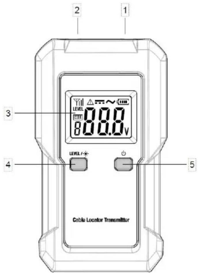
Figure 1. Transmitter
①. Black Terminal: Used to connect a black test lead.
②. Red Terminal: Used to connect a red test lead.
③. Display.
④. LEVEL 7
- Press this " " button to select a desired transmission level among the three transmission levels.
- Press and hold down this " " button for about 2 secs to turn on or off the backlight.
●This " "button is also used when you select a desired transmission code.
⑤. " Button.
- Press and hold down this " " button for about 1 sec to turn on or of transmitter.
●This " 🔊 button is used when you select a desired transmission code.
Transmitter Display
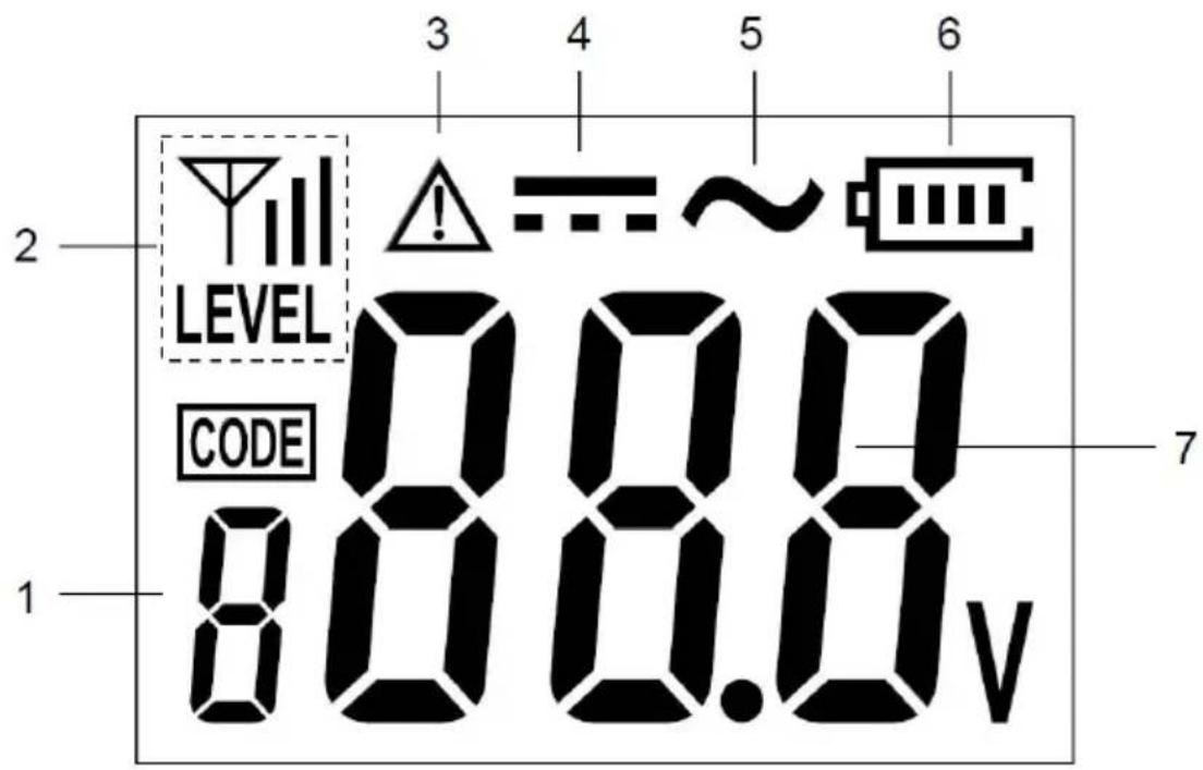
Figure 2. Transmitter Display
①. Transmission code display which shows the present transmission code of the transmitter. Transmission code is a number, such as 1, 2, 3, etc
②. Transmission level display which shows the present transmission
③. level of the transmitter. The higher the transmission level, the stronger the signal being transmitted.
LEVEL ...... denotes that the present transmission level is level 1.
LEVEL ...... denotes that the present transmission level is level 2.
LEVEL ...... denotes that the present transmission level is level 3.
④. Voltage alarm icon indicating that a voltage > 36V is being detected.
⑤. DC symbol indicating that a DC voltage is being detected.
⑥. AC symbol indicating that an AC voltage is being detected.
⑦. Battery level indicator.
When this indicator becomes " ", the battery in the transmitter is not high enough and must be replaced immediately.
⑧. Voltage value display which shows the external voltage value.
The transmitter can detect the DC or AC voltage of the circuit connect the terminals of the transmitter, the detecting range of the transmitter is dc to 600V dc, or 12V ac to 600V ac at 50Hz -60Hz.
If the voltage being detected is < E12V, " " will be shown or this voltage value display.
Note:
If the voltage between the two lines which are connected to the terminals of the transmitter is a DC voltage, the transmitter will display the absolute value of this voltage.
Receiver
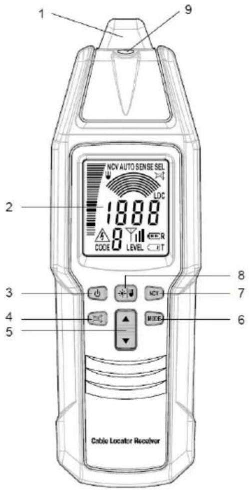
Figure 3. Receiver
①. Probe.
Signal sensing/detecting part of the receiver.
②. Display.
③. " Button.
Press and hold down this " button for about 1 sec to turn on or off tr receiver.
④. "Button."
Press this 📋 button to enable or disable the built-in buzzer.
When the buzzer is disabled, the receiver is mute and does not give acou signal indication.
⑤. "▲"/▼ button.
Used to increase or decrease the sensitivity of the receiver when the receiver in the manual mode or selective mode.
⑥. "MODE " Button.
Press this "MODE " button to switch among the automatic mode ( " AUTO appears ), manual mode( " SENSE " appears ), selective mode ( " SEL " appears ), and PINPOINT mode ( " LOC " appears ).
⑦. " NCV " Button.
Press this " NCV " button to enter or exit the non-contact mains voltage detection mode.
⑧. "Button."
Briefly press this - button to turn on or off the light. The light automatically turns off after about 60 secs.
Press and hold down this "button for about 1 sec to turn on or off tr backlight.
⑨. Light.
Receiver Display
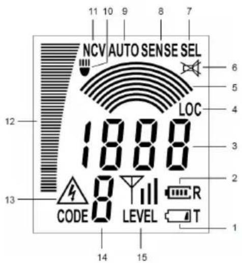
Figure 4. Receiver Display
①. Transmitter low battery indicator. When this low battery indicator ( ) appears, the battery in the transmitter is not high enough and must be rep immediately; otherwise the transmitter will not work normally
②. Receiver battery level indicator used to indicate the level of the battery in receiver. When this indicator becomes "T", the battery in the receiver is not high enough and must be replaced immediately; otherwise the receiver not work normally.
③. A display that has two kinds of uses as described below:
- In the automatic mode, PINPOINT mode, or mains voltage detection mode, this display area shows the numeric value of the intensity of the signal be detected by the receiver. The higher the intensity of the signal being detected by the higher the numeric value being displayed.
- In the manual mode or selective mode, this display area shows the pres sensitivity degree (1 - 8) of the receiver.
④. Indicates that the receiver is in the PINPOINT mode.
⑤. Arcs graph display. In the manual mode or selective mode, this display graphically shows the present sensitivity degree of the receiver. One arc on arcs graph display represents one sensitivity degree.( For example, the graph " " stands for sensitivity degree 2, the graph " " stands for sensitivity degree 3, and so on ). The more arcs present on this display, higher sensitivity degree the receiver.is at, and the higher sensitivity the rec has.
⑥. Indicates that the built-in buzzer of the receiver is disabled and that the receiver is mute.
⑦. Indicates that the receiver is in the selective mode.
⑧. Indicates that the receiver is in the manual mode.
⑨. Indicates that the receiver is in the automatic mode.
10. Indicates that the light on the receiver is has been turned on.
11. Indicates that the receiver is in the mains voltage detection mode
12. Bargraph that indicate the present intensity of the signal being detected by receiver. The higher the bargraph, the higher the present intensity of the signal being detected by the receiver.
13. An alarm icon that will appear when the receiver detects a mains voltage
14. Transmission code display that shows the present transmission code of th
transmitter.
- Transmission level display that shows the present transmission level of the transmitter.
" " denotes that the present transmission level of the transmitter is level 1 LEVEL
" LEVEL denotes that the present transmission level of the transmitter is level 2
" " denotes that the present transmission level of the transmitter is level 3
PRODUCT INSTRUCTION
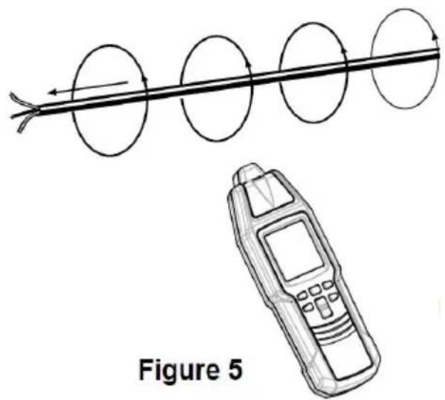
The instrument consists of a transmitter and a receiver. The transmitter generates AC signal of a modulated current. The current of the ac signal flc through the connected conductor generating a electromagnetic field around this conductor. This electromagnetic field induces a voltage in the receiver coils. F the automatic mode and manual mode, the receiver works with three coils at does not depend on the direction of receiver. A selective and position-depend search is performed in the selective mode or PINPOINT mode with only one coil. The induced voltage is amplified, decoded, and converted by the receive and finally indicated on the receiver screen. For any application, ensure that is a closed loop for the flowing signal in the conductor when connecting the transmitter.(see Figure 5)
In the PINPOINT mode, when the longitudinal axis of the receiver is parallel, the line conductor which is connected to the transmitter and the receiver is above this line conductor (see Figure 6), the signal received by the receiver its maximum. The PINPOINT mode is used to accurately locate a line condu Buried under wall/earth surface.
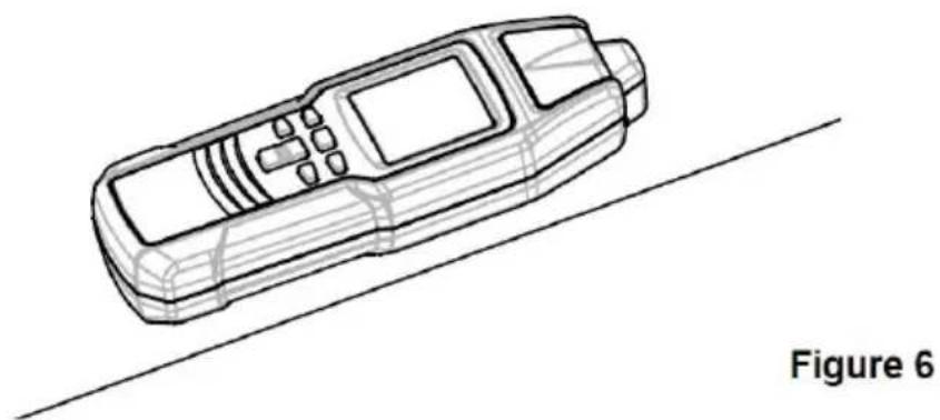
natural_image
Line drawing of a mobile phone with a diagonal line, labeled 'Figure 6' (no text or symbols on the device itself)In the mains voltage detection mode, the receiver can detect 50Hz - 60Hz electromagnetic field in any direction.
LOCATOR IN COMPLETE CIRCUITS
●1st Possibility ( one pole application )
Connect the transmitter to only one conductor. The second conductor is the ground. This arrangement causes a signal current to flow through the condu and to be transmitted to ground, similar to a radio and receiver. Hereafter, call the above described operation one-pole application.
●2nd Possibility ( double-pole application )
Connect the transmitter to the mains. In this condition, the modulated current flows through the phase and then returns to the transmitter via the neutral. There is another possibility for voltage free systems by connecting the transmitter to two line terminals while short-circuiting the other line ends. The complete circuit is created. Then, the transmitter is supplied by the built-in battery. Hereafter, we call this operation double pole application.
Note:
The instrument can only detect or locate lines which are connected correctly in accordance with the physical principle described.
In double-pole application, the PINPOINT mode of the receiver does not work. Do not use the PINPOINT mode in any double-pole application.
IMPORTANT APPLICATIONS
●In open circuits ( one pole application )(see Figure 7)
Line interruptions in walls and floors. Finding and tracing of lines, sockets, junction box, switches, etc. For house installations.
The black terminal of the transmitter must be connected to a suitable earth typical example is a properly earthed socket. The tracing depth amounts to 2 meters.
Note: The tracing depth depends on the medium and application.
Figure 7
●In complete circuits ( double pole application )(see Figure 8)
When detecting short-circuits or during wire sorting, i.e. circuits with or without voltage. Voltage-free circuits are directly supplied by the transmitter battery. live circuits, the transmitter is mainly supplied by the circuit connected. The transmitter is voltage-proof up to 600V AC/DC.
Example for a complete circuit: Complete circuits are appropriate for: i.e. detecting switches, sockets, etc in live installations.
Note:
-
The tracing depth amounts to 0 - 0.5 meter. The tracing depth depends on medium and application.
-
Increasing the transmission level from level 1 to level 3 with the " " bit increases the detecting distance of the receiver by a factor of about 4.
- When connecting the transmitter in a live circuit, adhere to local and natural safety codes. To avoid electric shock, do not touch any naked conductor hand or skin.
Figure 8
CARRYING OUT MEASUREMENT
Tracing and locating of lines, sockets, switches and junctions in house installations circuits (one-pole application)
Requirements:
●The circuit must be dead.
●Neutral line and ground must be fully operational.
- Connect the transmitter to phase and ground according to Figure 9.
●Carry out this example as described in the application example.
In the one-pole application, lateral circuit branches can also be trac
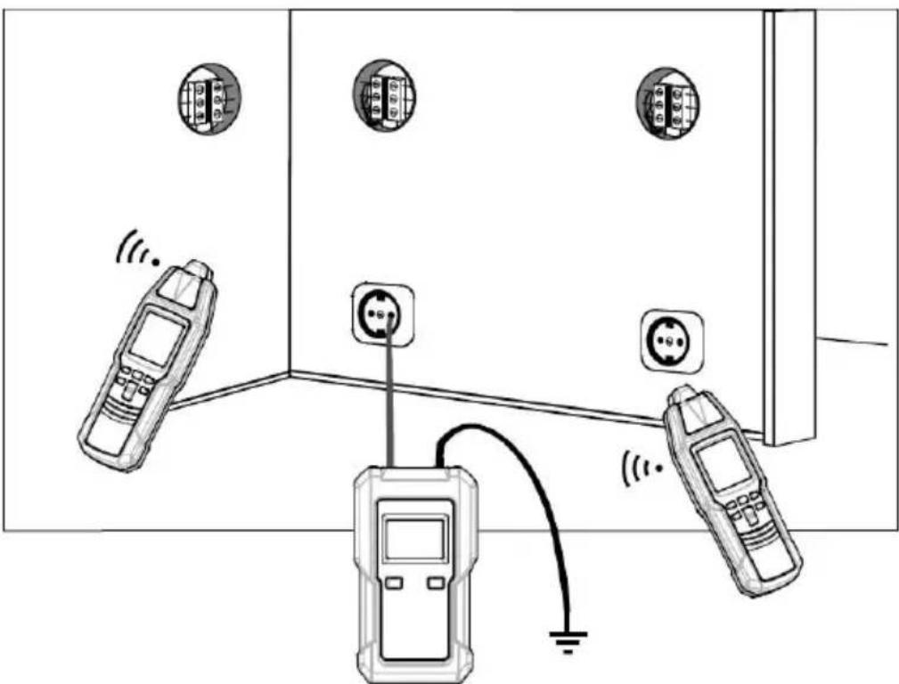
Figure 9
Note:
- If the supply cable fed with the signal via the transmitter is located direct parallel to other conductors (e.g. cable duct) or if these conductors are on the signal is also input into the other conductors.
- Increasing the transmission level from level 1 to level 3 with /the " " button increases the detecting distance of the receiver by a factor of about
- Setup of the receiver: manual mode, minimal sensitivity. If necessary, adjust the sensitivity of the receiver according to the actual condition during detect
●Max. tracing depth: about 2 meters.
Locating of line interruptions ( one-pole application )
Requirements:
●The circuit must be dead.
●All lines that are not required must be connected to the auxiliary ground accordance with Figure 10.
- Connect the transmitter to one lead and to ground according to Figure 10
●Carry out this example as described in the application example.
Line interruption in the plastic-sheathed cable.
The ground connected to the transmitter should be earth from a properly earthed socket or a water pipe that is properly earthed.
When tracing line interruption in a multicore cable, note that all remaining I in plastic-sheathed cable must be grounded in accordance with the regulations. This is required to avoid crosscoupling of the fed signal (by a capacitive e
The tracing depth for sheathed cable and conductors are different, because individual leads in the sheathed cable are twisted around themselves.
The transition resistance of a line interruption must be > 100 kOHM. The verification of resistance can be done by using a multimeter.
Systematically circle around the interruption while changing the sensitivity of receiver. By this means, the line interruption can be located in the end.
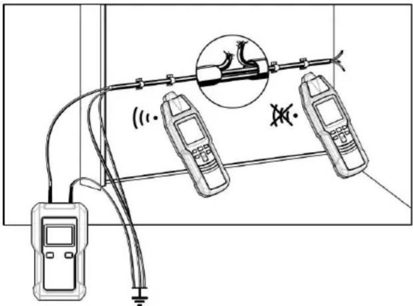
Figure 10
Note:
- Increasing the transmission level from level 1 to level 3 with the " " button increases the detecting distance of the receiver by a factor of about
- Setup of the receiver: manual mode, minimal sensitivity. If necessary, adjust the sensitivity of the receiver according to the actual condition during detect
●Max. tracing depth: about 2 meters.
When locating a line interruption using one transmitter to feed from o conductor end, the location of line interruption may not be precisely in case of bad condition due to a field disturbance. This drawback can easily avoid when using two transmitters (one from each end) for interruption detection. In this instance, each of the transmitters are set different transmission code (e.g. one transmitter is set to code "1 other transmitter is set to code "6").
Your instrument includes only one transmitter. If you need a second transmitter, you can separately order one or more transmitters from our company.
If the transmitters are connected in accordance with Figure 11, the re displays the transmission code "1" at the left side of the line inter you continue further than the interruption, toward the right, the receive displays the transmission code "6". If the receiver probe is directly the line interruption, no transmission code is displayed, due to the overlapping of both transmitter signals. The line interruption is located between the displayed codes "1" and "6".
Requirements:
●The circuit must be dead.
●All lines which will not be used must be connected to the auxiliary as shown Figure 11.
- Connect the two transmitters as shown in Figure 11.
●Proceed as described in the application example.
The ground connected to the transmitter and to the wires not being can be an auxiliary ground, the ground contact of a properly earthed or a properly grounded water pipe.
When carrying out line interruption locating on a multi-wire shielded ca make sure that all unused wires are orderly grounded. This is required avoid inductive disturbance ( by capacity coupling ).
The locating depth for shielded conductors and cables varies, because individual wires within the shield are twisted.
The transition resistance of a line interruption must be > 100 kOHM. verification of resistance can be done by using a multimeter.
Systematically circle the line interruption by changing the sensitivity of receiver.
Note:
- Increasing the transmission level from level 1 to level 3 L with / - the " "
button increases the detecting distance of the receiver by a factor of about - Setup of the receiver: manual mode, minimal sensitivity. If necessary, adjust the sensitivity of the receiver according to the actual condition during detect
●Max. tracing depth: about 2 meters
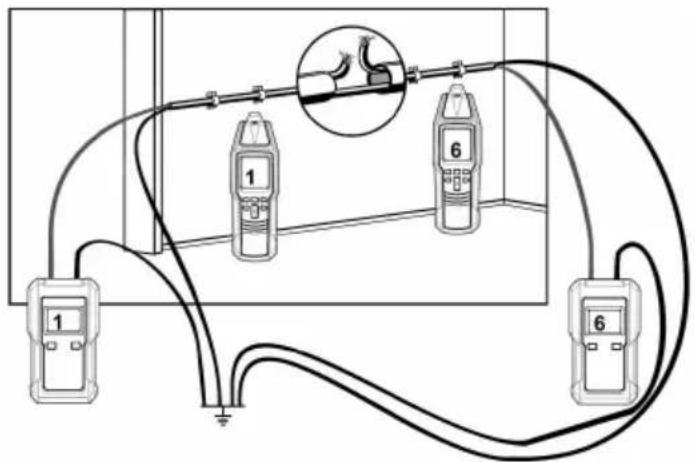
Figure 11
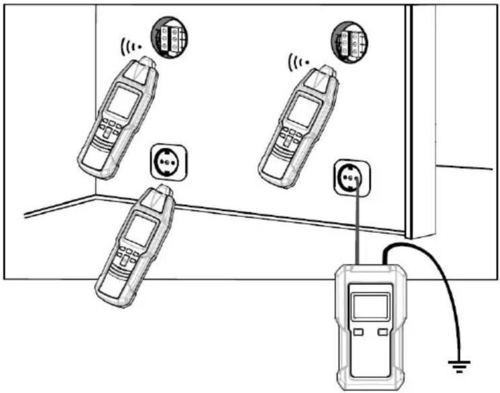
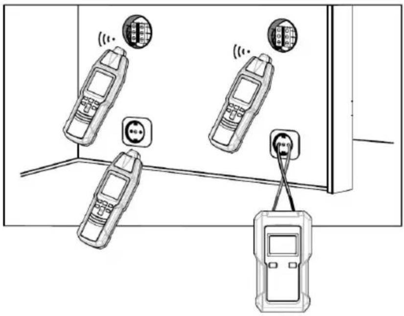
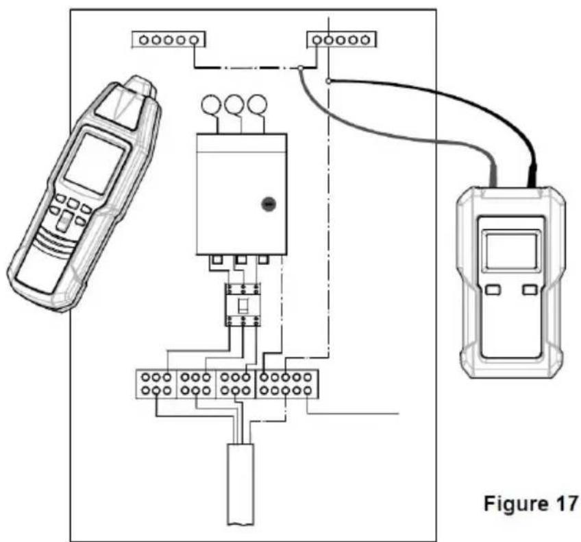
LOCATING CIRCUIT BREAKER OR FUSE THAT SUPPLIES AN OUTLE (DUAL-POLE APPLICATION)
Warning: Adhere to local and national safety codes. To avoid electric do not touch any naked conductor with hand or skin.
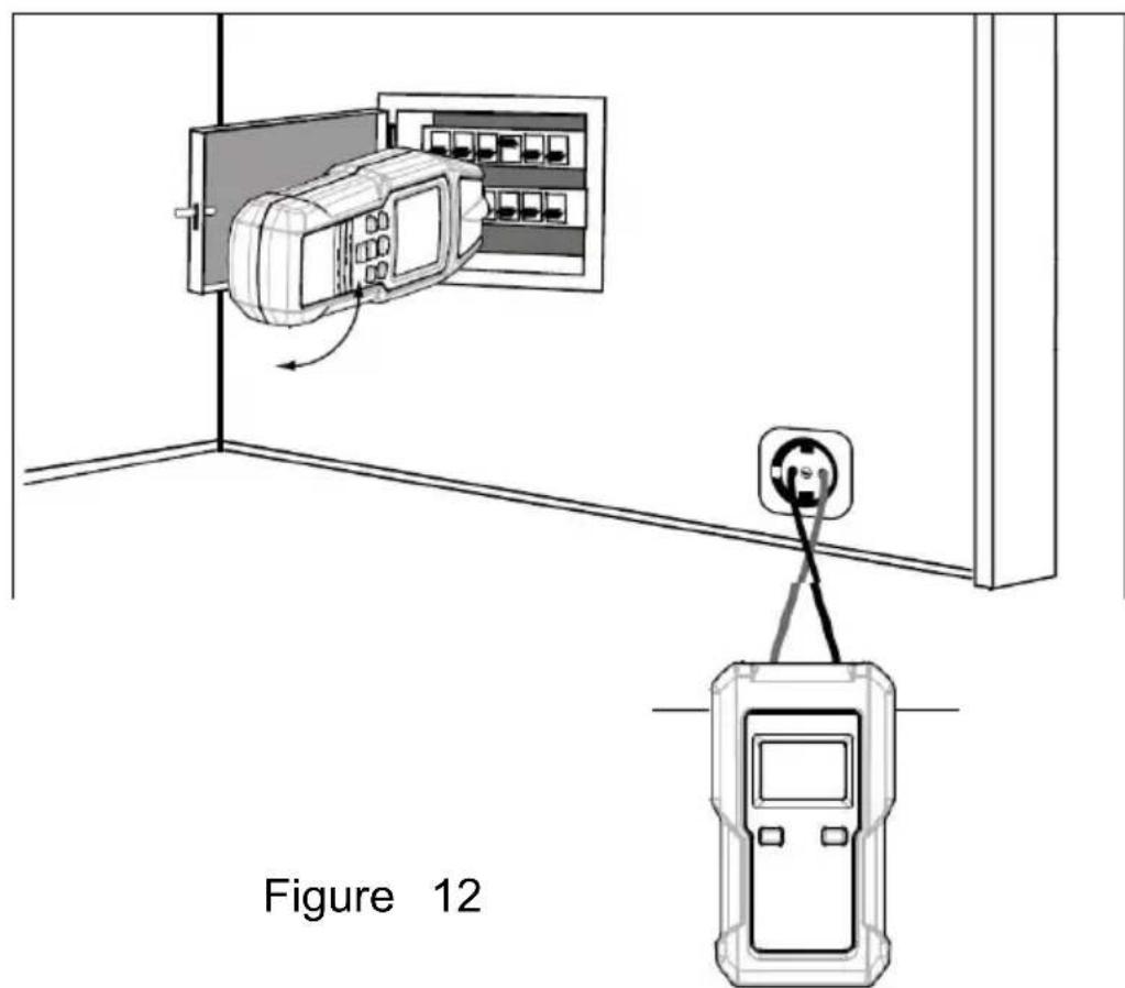
Refer to Figure 12, connect the red and black terminals of the train to the desired energized AC wall outlet, make sure that the red term the transmitter is connected to the Live terminal of the outlet and the terminal of the transmitter is connected to the Neutral terminal of the The transmitter displays the value of the voltage of the outlet. Set the transmission level of the transmitter to level 1, the transmitter will dis

" as an indication.
Go to the circuit breaker panel box, place the flat top of the pin, the receiver directly onto circuit breaker or fuse ( refer to Figure 1). Hold the receiver so that it is perpendicular to the breakers or fus
shown. Slowly move the receiver up and down over the rows of breakers or fuses. During this process, if two or more circuit breaks (or fuses) caused the receiver to give signal indication, decrease receiver's sensitivity and then scan slowly all breakers or fuses once more.
When you finds the only one circuit breaker or fuse at which the receiver gives signal indication, turn off the circuit breaker (or ren the fuse). If the receiver stops giving audio and visual signal ind and the transmitter displays " instead of a voltage reading, the circuit breaker (or the fuse) is the circuit breaker (or fuse) s the outlet. If the transmitter still displays a voltage reading, it mean the circuit breaker (or the fuse) is not the circuit breaker (or supplies the outlet.
The detection or assignment of the circuit breaker or fuse strong depends on the wiring realized within the distribution. To obtain a as precise as possible, the cover should be removed and the supply line to the fuse should be traced.
Note:
- If the circuit breaker panel box is not far from the transmitter, the transmission level of the transmitter must be set to level 1. If the circuit breaker panel box is too far from the transmitter so that impossible to perform detection and locating, you should appropriately increase the transmission level of the transmitter according to actual condition.
- Increasing the transmission level from level 1 to level 3 with the "LEVEL" button increases the detecting distance of the receiver by a factor of about 4.
- Setup of the receiver: selective mode, minimal sensitivity.
- Safety cutouts of different manufacturers have different installation positions for magnetic coils. If no evident signal can be detected the receiver, it is recommended to clockwise or counterclockwise the receiver by 90 angle
- To avoid electric shock, do not touch any naked conductor with or skin.
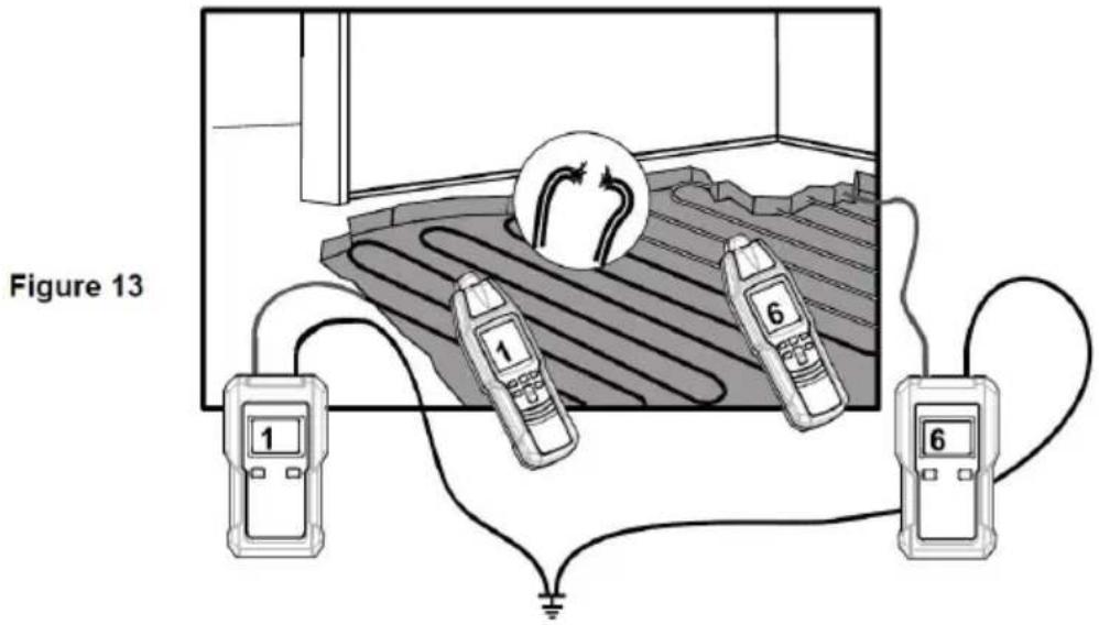
Error detection for an electrical floor heating ( one-pole applica
Requirements:
●The circuit must be dead.
●A second transmitter is required for this application.
- Connect the transmitters as shown in Figure 13.
- Carry out this example as described in the application example. If a shield mat or shield wiring is located above the heating wire ground connection may exist. If required, separate the shield from ground connection, and remember to restore the ground connection after you finish the detection.
Note:
- Increasing the transmission level from level 1 to level 3 with the "LEVEL" button increases the detecting distance of the receiver by a factor of about 4.
- Setup of the receiver: manual mode, minimal sensitivity. If necessary, adjust the sensitivity of the receiver according to the actual condition during detection.
●Max. tracing depth: about 2 meters
Locating of short-circuits in conductors ( double-pole applicatio
Requirements:
●All circuits within the cable must be dead.
- Connect the transmitter in accordance with Figure 14.
- Carry out this example as described in the application example.
Note that the tracing depth for sheathed cable and conductors are different because the individual leads in the sheathed cable are twi around themselves.
Usually, short-circuit can only be correctly detected when the short-circuit resistance is lower than 20 Ohm. The verification of the short-circuit resistance can be done by using a multimeter. If the short-circuit resistance is more than 20 Ohm, you can try the experiment to detect the error location by means of the line interrupt detection method.
Systematically circle round the interruption by changing the sensitivity of the receiver.
Note:
- Increasing the transmission level from level 1 to level 3 with the "LEVEL" button increases the detecting distance of the receiver by a factor of about 4.
- Setup of the receiver: manual mode, minimal sensitivity. If necessary, adjust the sensitivity of the receiver according to the actual condition during detection.
●Max. tracing depth: about 0.5 meter
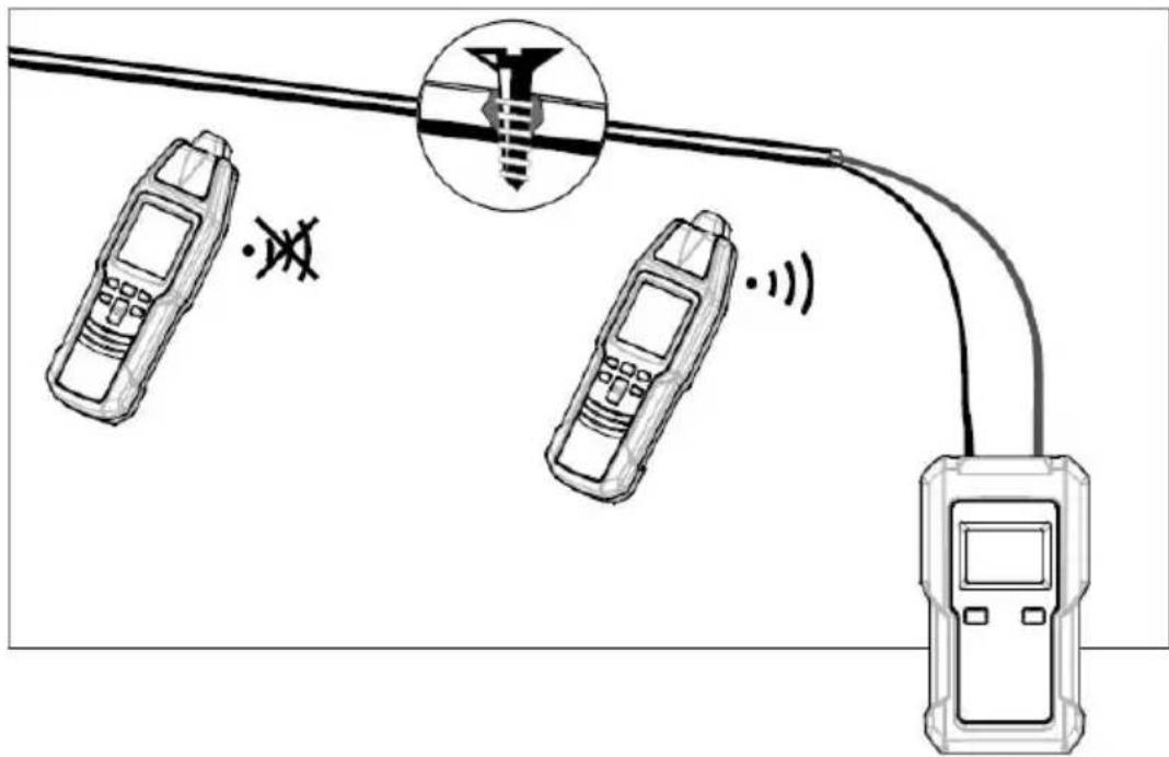
Figure 14
Tracing installed water and heating pipes ( one-pole applicati
Requirements:
●The line to be located must be separated from the equipotential bonding. ( When you finish tracing water or heating pipes, remer to restore the line's connection which you have disconnected.)
- Connect the transmitter in accordance with Figure 15.
●For safety reasons, the electrical system must not be live!
Connect the black terminal of the transmitter to the ground termina a properly earthed socket, and connect the red terminal of the transmitter to the conductor to be traced or located. Now the feed can be traced.
Note:
- Increasing the transmission level from level 1 to level 3 with the "LEVEL/ON" button increases the detecting distance of the receiver by a factor of about 4.
- Setup of the receiver: manual mode, minimal sensitivity. If necessary, adjust the sensitivity of the receiver according to the actual condition during detection.
●Max. tracing depth: about 2 meters.
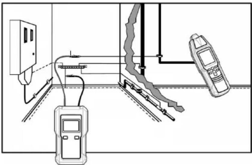
Figure 15
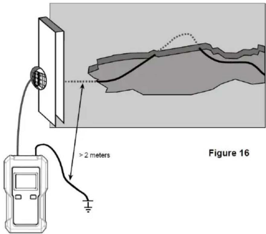
Tracing conductors buried in the soil ( single-pole applicatio
The connection is realized in compliance with Figure 16.
Warning: Ensure that the current circuit is not live.
Note: Make sure that the distance between the connection to the ground and the conductor to be detected is high. If the distance is too short, no definite assignment of the received can be made to one conductor. ( See Figure 16.)
The max. tracing depth is about 2 meters. The tracing depth strong depends on the soil characteristics and the instrument's settings.
Set the receiver to automatic mode. Now, search or trace the con by means of the signal intensity displayed. When circling the receive slowly across the conductor to be searched, the displayed values change considerably. The display of the maximum signal intensity is performed directly via the conductor. The signal intensity level decreases with increasing distance of the fed-in signal (transmitter
Practical application example.
In order to determine all electrical lines of a house within one wo process, proceed as follows:
- Remove the bridge in the main distribution between "PE" and Warning: For safety reasons, the system must not be live!
- Connect the transmitter to the system in compliance with Figure 1. Now, the neutral conductor present in the system may be followed
Note:
- Increasing the transmission level from level 1 to level 3 with the "LEVEL" button increases the detecting distance of the receiver by a factor of about 4.
- Setup of the receiver: manual mode, minimal sensitivity. If necessary, adjust the sensitivity of the receiver according to the actual condition during detection.
●Max. tracing depth: about 2 meters
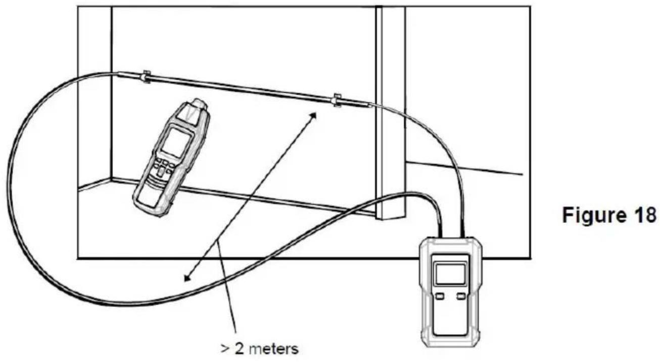
If the dual-pole application is carried out on multi-wire cables (NYM 3 x1.5mm2), the location depth is widely limited. This is best the go-and-return lines are installed very closely. And as a result, strong distortion of the magnetic field occurs. The electro-magnetic field may not develop at the bottleneck. This limitation can easily be eliminated when using a separate conductor as the return line. This separate conductor allows a larger spreading of the electro-magnetic field. Any conductor or cable reel can be used as separate return conductor.
When tracing the conductors, make sure that the distance betw the feeder line and the return line is larger than the location dept practical applications, this amounts to approx. 2.0 meters.
For this application, humid walls, plaster, etc. have only an insignificant influence on the location depth.
Requirements:
●The current circuit must not be live.
- Connect the transmitter in compliance with Figure 18.
●The distance between the feeder line and the return line must be least 2.0 to 2.5 meters or more.
●Proceed as described in the application example.
Note:
- Increasing the transmission level from level 1 to level 3 with the "LEVEL/2" button increases the detecting distance of the receiver by a factor of about 4.
- Setup of the receiver: manual mode, minimal sensitivity. If necessary adjust the sensitivity of the receiver according to the actual condition during detection.
●Max. tracing depth: about 2 meters
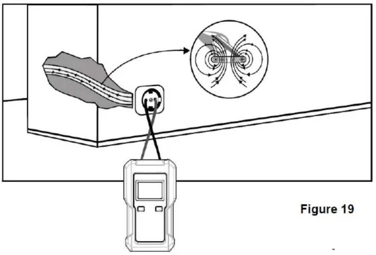
The reach will be improved when seeking the tension
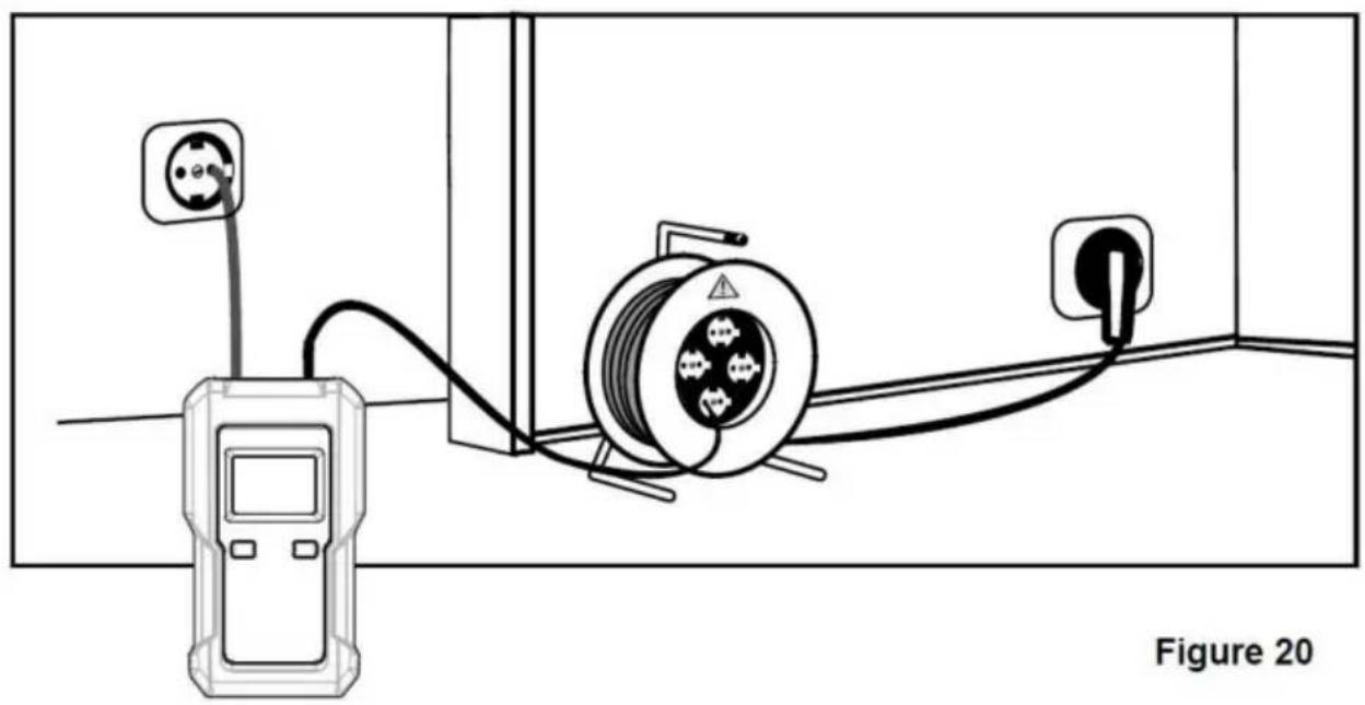
If the transmitter is connected to a live line and a neutral line, signal is conducted on two parallel lines( see Figure 19 ).
The twisting of the lines can sometimes cause the signals to ca each other. In this case, the maximum effective detecting radius of receiver is only about 0.5 meter.
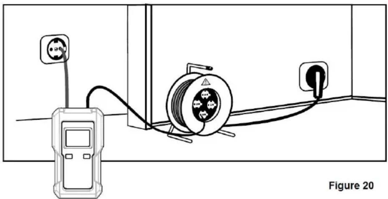
To eliminate the effect pointed out in Figure 19, the connection be carried out like Figure 20. In this figure, a separate cable is up the return line, which can increase the effective detecting radius of receiver to about 2.5 meters or higher. A larger distance return line be provided through the cable reel.
Pay attention to the distance between the receiver and the line checked, so that the line can be clearly determined according to the signal indication of the receiver.
Comply with the relevant national and local safety laws and regulations when performing connections on live circuits.
Note:
Increasing the transmission level from level 1 to level 3 with the "LEVEL" button increases the detecting distance of the receiver by a factor of about 4.
natural_image
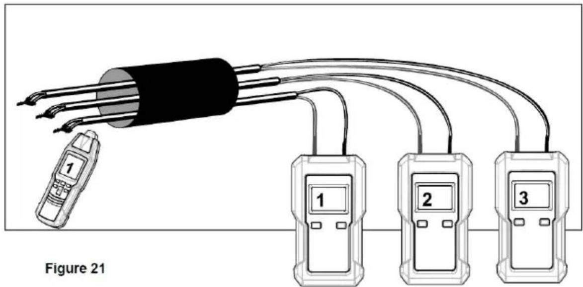
Diagram of electrical connections showing a power outlet, cable spool, and plug (no text or symbols)Sorting or determination of conductors already installed ( double-pole application )
Requirements:
●All circuits within the cable must not be live.
●The lead terminals must be twisted and electrically connected between each other.
●You need several transmitters with different transmission codes.
- Connect the transmitter according to Figure 21.
●Carry out this example as described in the application example.
For this application example, please notice that the stripped lead terminals are twisted with each other. The electrical connection between the stripped lead terminals must be good.
If you have only one transmitter, the sorting of the sheathed cal can done by sequentially reconnecting the transmitter.
Note:
Increasing the transmission level from level 1 to level 3 with the "LEVEL/2" button increases the detecting distance of the receiver by a factor of about 4.
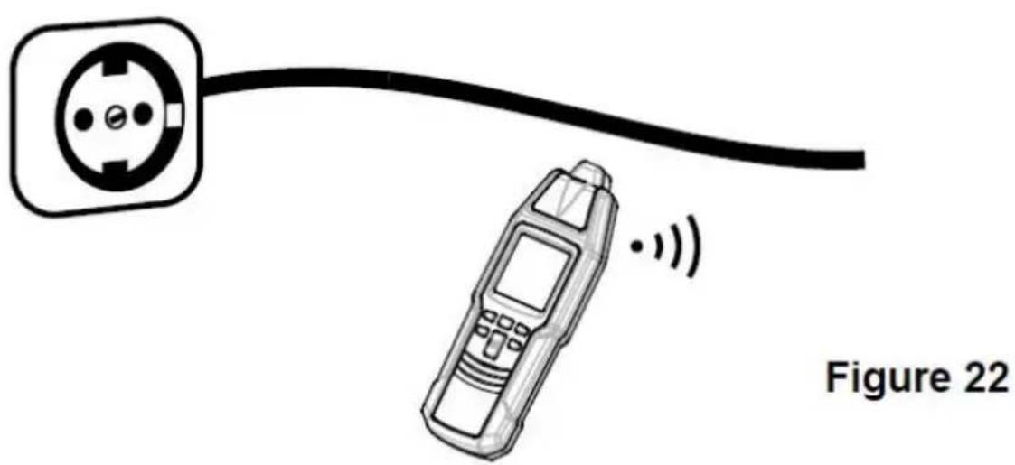
The test is performed in compliance with Figure 22. For this application, no transmitter is required.
Select the mains voltage detection mode with the "NCV" button, the receiver. (When the mains voltage detection mode is selected, receiver displays the symbol "NCV" as an indicator.) Move the receiver probe close to the cable to be tested, and observe the right to see where it gives signal indication.
The bargraph display indicating the signal intensity and the signal sound frequency depend on the level of the voltage of the conduct under test, the distance between the receiver and the live conduct the insulation of the conductor, etc.
The higher the frequency of the signal sound of the receiver, th higher the voltage, or the lower the distance to the conductor.
Warning:
●The signal intensity indicated by the receiver does not necessarily indicate the level and type of the voltage of the conductor under The value of a voltage can only be determined by a professional measurement tool such as a multimeter.
●The signal indication of the receiver is affected by the distance between the receiver probe and the conductor under test, the voice of the conductor, the insulation of the conductor, etc. The conduct under test may be live even if the receiver does not give any indication. To avoid electric shock and personal injury, do not take any conductor with hand or skin.
- Before and after each use, verify the receiver's operation by detecting a known energized power socket. Do not use the receiver if it operates abnormally or is damaged.
To avoid interference, do not use the receiver where there is strong environmental electromagnetic field; otherwise the test result may be wrong.
natural_image
Illustration of a mobile phone connected to a power outlet, labeled Figure 22 (no text or symbols on the device itself)Setting the transmission code of the transmitter
☐ Make sure that the transmitter is off.
On the transmitter, press and hold down the " " button while holding down the LEVEL / button. When the transmitter has turned on, release all the buttons.
Briefly press the LEVEL / button until the desired transmission code appears on the transmitter display.
To exit the transmission code setting mode, press and hold down "button for about 1 sec. The transmitter turns off.
Using the illumination function of the receiver
Make sure that the receiver is on, then briefly press the " " button to turn on or off the light on the receiver. The light turns automatically after about 60 secs.
MAINTENANCE
Warning
The instrument is not waterproof. Do not let water or any liquid enter the case or terminals of the instrument.
Before cleaning the instrument, turn off the instrument and disconnect the instrument from any cable/lead.
Cleaning:
Periodically wipe the case with a damp cloth. Do not use abrasive solvents.
General Maintenance:
Except replacing battery and fuse, never attempt to repair or ser the instrument.
Store the instrument in a dry place when not in use. Do not stand an environment with intense electromagnetic field.
If the instrument fails, check and replace (as needed) the bat and fuse and/or review this manual to verify proper operation.
BATTERY REPLACEMENT
Replacing the battery in the transmitter:
When the battery level indicator on the transmitter display becomes "or when the receiver display shows", the battery in the transmitter is not high enough and you must replace it immediately otherwise the transmitter will not operate normally or the measurement/detection result may be wrong.
To replace the battery, turn off the transmitter and then disconnect transmitter from any cable/lead and circuit. Remove the screw on the battery cover of the transmitter and then remove the battery cover. Replace the old battery with a new one of the same type, make that the polarity connections are correct. Reinstall the battery cover the screw.
Warning
To avoid electric shock, turn off the transmitter and then disconnect the transmitter from any cable/lead and circuit before opening the battery cover or case of the transmitter.
Replacing the battery in the receiver:
When the low battery indicator "R" appears on the receiver display, the battery in the receiver is not high enough and you m replace it immediately; otherwise the receiver will not operate normal or the detection result may be wrong.
To replace the battery, turn off the receiver first. Remove the so the battery cover of the receiver and then remove the battery cover. Replace the old battery with a new one of the same type, make that the polarity connections are correct. Reinstall the battery cover the screw.
REPLACING THE FUSE IN THE TRANSMITTER
The fuse in the transmitter protects the transmitter against overload or faulty manipulation.
If the output signal generated by the transmitter is weak and can be increased to a normal level, the fuse in the transmitter may be damaged.
Use the following procedure to check whether the fuse is damage
- Disconnect the transmitter from all cables/leads connected.
- Turn on the transmitter, then set its transmission level to level 1. " "Is shown on the transmitter display. Connect one end of a test lead to the red terminal of the transmitter.
- Turn on the receiver. The receiver defaults to the automatic mode and the symbol "AUTO" appears on the receiver display as a indicator.
- Place both the transmitter and receiver on a wooden desk (or nonmetallic desk). Move the receiver probe close to the test lead is connected to the red terminal of the transmitter, and adjust the position of the receiver until the receiver displays a reading which approximates 700. Do not move the receiver from now on and i following procedure, and note down this reading.
- Do not move the transmitter. Connect the unused end of the test to the black terminal of the transmitter.
- If the fuse in the transmitter is good, the reading on the receive display will roughly double.
If needed, use the following steps to replace the fuse:
- Turn off the transmitter. Disconnect the transmitter from any cable/lead and circuit.
- Remove the screw on the battery cover of the transmitter, then remove the battery cover, and then remove the battery.
- Remove the screws on the back cover of the transmitter, and the remove the back cover. Replace the damaged fuse with a new the same ratings. Reinstall the back cover and its screws. Then reinstall the battery, the battery cover, and the screw correctly.
The transmitter uses one fuse whose ratings are: 500mA/600V, F action, ∅6.35X32mm.
INSTRUMENT CALIBRATION
To ensure measurement accuracy, the instrument must be periodically calibrated by our company. The recommended calibration interval is one year.
If the instrument is used very often or if it is used under rough conditions, we recommend shorter intervals. If the instrument is use few times only, the calibration interval can be extended to 3 years
TRANSPORT AND STORAGE
Please keep the original packaging for later transport, e.g. for calibration. Any transport damage due to faulty packaging will be excluded from warranty claims.
In order to avoid damage caused by battery leakage, remove batteries from the instrument if you do not use the instrument for period of time.
When the instrument is not in use, it must be stored in dry are without intense electromagnetic field.
TECHNICAL DATA
Transmitter:
Output Signal: 125kHz
External Voltage Measuring Range: 12V dc 600V dc, or 12V ac 6 at 50Hz 60Hz
Display: LCD
Measurement Category: CAT III 600V
Pollution Degree: 2
Battery: 9V battery, 6F22 or equivalent, 1 piece
Operating Environment: Temperature:°C to 40C
Relative Humidity: < 75%
Storage Environment: Temperature: -20 to 60
Relative Humidity: < 85%
IP Degree: IP20
Operating Altitude: 0 to 2000 meters
Size: 133mm x 76mm x 32mm
Weight: About 207g (including battery)
Receiver:
Tracing Depth: The tracing depth depends on medium and applica
Cable Locator Mode: Approx. 0 to 2 meters (single-pole applicati
Approx. 0 to 0.5 meter (double-pole application or 0 to 2.5 meters (only when a separate re line is used in double-pole application)
Note: The distance between the transmitter and the receiver must be 2m. In double-pole applications, do not use the PINPOINT mode.
Non-Contact AC Voltage Detection Range: 90V ac 264V ac, at 560Hz
Display: LCD
Battery: 9V battery, 6F22 or equivalent, 1 piece
Operating Environment: Temperature: 0°C to 40°C
Relative Humidity: < 75%
Storage Environment: Temperature: -20°C to 60°C
Relative Humidity: < 85%
IP Degree: IP20
Operating Altitude: 0 to 2000 meters
Size: 186mm x 60mm x 35mm
Weight: About 234g (including battery)
APPENDIX: TEST LEAD ASSEMBLY
Before you use the supplied test leads that are without a probe, must connect them to the alligator clips as described as follows:
- Remove the two protective caps at the two ends of each test le
- Refer to Figure 23, insert the specified end of each test lead into corresponding alligator clip until the end is reached.
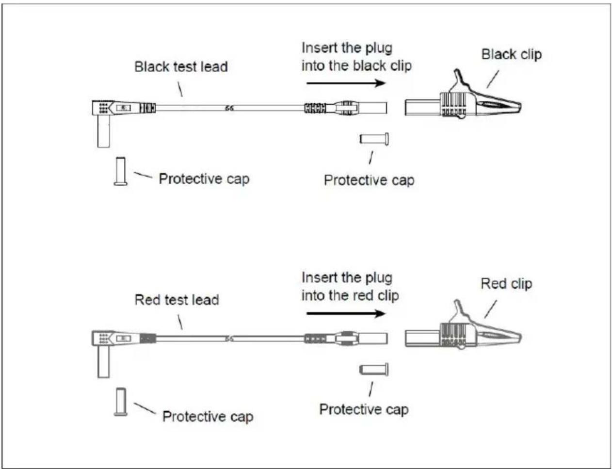
Figure 23
NOTE
●This manual is subject to change without notice.
●Our company will not take the other responsibilities for any loss.
●The contents of this manual can not be used as the reason to instrument for any special application.
Accessories list
- Test leads *1
- Test probes *2
- Test the clips *2
- L-shaped grounding rod *1
- Storage bag *1
- Instruction manual *1
- 9V lithium battery *2
- Phillips screwdriver *1
- USB charging cable *1
DISPOSAL OF THIS ARTICLE
Dear Customer,
If you at some point intend to dispose of this article, then please keep in mind that many of its components consist of valuable materials, which can be recycled.
Please do not discharge it in the garbage bin, but check with your local council for recycling facilities in your area.
natural_image
Symbol of a trash bin crossed with a diagonal line and a horizontal bar below (no text or labels)Address: Baoshanqu Shuangchenglu 803long 11hao 1602A-1609shi Shanghai
Imported to AUS: SIHAO PTY LTD, 1 ROKEVA STREETEASTWOOD NSW 2122 Australia
Imported to USA: Sanven Technology Ltd, Suite 250, 9166 Anaheim Place, Rancho Cucamonga, CA 91730
| EC | REP |
SHUNSHUN GmbH
Römeräcker 9 Z2021, 76351
Unit 5 Albert Edward House, The
Pavilions Preston, United Kingdom
Made In China
VEVOR®
TOUGH TOOLS, HALF PRICE
Technical Support and E-Warranty Certificate
www.vevor.com/support
VEVOR®
TOUGH TOOLS, HALF PRICE
INSTRUCTIONS PRODUIT
Émetteur
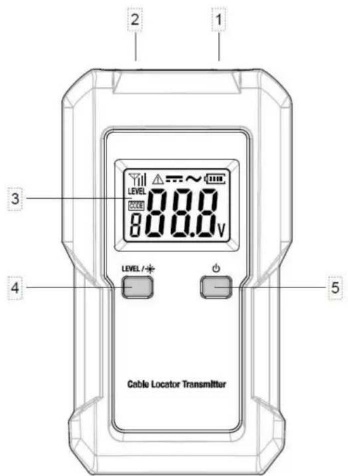
Figure 1. Transmitter
Figure 3. Receiver
①. Sonde.
Figure 4. Receiver Display
INSTRUCTIONS PRODUIT
natural_image
Line drawing of a mobile phone with control panel and keypad, resting on a diagonal line (no text or symbols on device)APPLICATIONS IMPORTANTES
EFFECTUER LA MESURE
Figure 9
Note:
Figure 10
Note:
Figure 11
LOCALISATION DU DISJONCTEUR OU DU FUSIBLE QUI ALIMENTE UNE PRISE (APPLICATION BIPOLAIRE)
Note:
Figure 14
Figure 15

natural_image
Diagram of electrical connections with a power meter and cable, labeled Figure 20 (no text or symbols on components)natural_image
Diagram showing a plug connected to a mobile phone with signal waves, labeled Figure 22 (no text or symbols on the diagram itself)The instrument is not waterproof. Do not let water or any liquid enter the case or terminals of the instrument.
Before cleaning the instrument, turn off the instrument and disconnect the instrument from any cable/lead.
Nettoyage:
Figure 23
NOTE
DISPOSAL OF THIS ARTICLE
Dear Customer,
If you at some point intend to dispose of this article, then please keep in mind that many of its components consist of valuable materials, which can be recycled.
Please do not discharge it in the garbage bin, but check with your local council for recycling facilities in your area.

natural_image
Symbol of a trash bin with crossed lines indicating no waste or restriction, and a solid black rectangle below (no text or labels)Adresse : Baoshanqu Shuangchenglu 803long 11hao 1602A-1609shi
Shanghai
Importé en Australie : SIHAO PTY LTD, 1 ROKEVA STREETESTWOOD
NSW 2122 Australie
Lieu, Rancho Cucamonga, CA 91730
| REPRÉSENTANT CE |
SHUNSHUN GmbH
Römeräcker 9 Z2021, 76351
Linkenheim-Hochstetten, Allemagne
| REPRÉSENTANT | DU ROYAUME-UNI |
Groupe Pooledas Ltd
www.vevor.com/support
KABEL-LOKATOR
MODELL:TS552
Figure 3. Receiver
①. Sonde.
Figure 4. Receiver Display
natural_image
Line drawing of a mobile phone with control panel and keypad, resting on a diagonal line (no text or symbols on device)MESSUNG DURCHFÜHREN
Abbildung 9
Notiz:
Abbildung 10
Notiz:
Abbildung 11
Figure 14
natural_image
Technical diagram showing electrical measurement setup with handheld devices and a mobile phone (no text or labels)Figure 15

natural_image
Diagram of electrical connections with a power meter, cable, and plug, labeled Figure 20 (no text or symbols on components)natural_image
Diagram showing a plug connected to a mobile phone with signal waves, labeled Figure 22 (no text or symbols on the diagram itself)The instrument is not waterproof. Do not let water or any liquid enter the case or terminals of the instrument.
Before cleaning the instrument, turn off the instrument and disconnect the instrument from any cable/lead.
Reinigung:
Figure 23
NOTIZ
DISPOSAL OF THIS ARTICLE
Dear Customer,
If you at some point intend to dispose of this article, then please keep in mind that many of its components consist of valuable materials, which can be recycled.
Please do not discharge it in the garbage bin, but check with your local council for recycling facilities in your area.

natural_image
Symbol of a trash bin with crossed lines indicating no waste or discharge, and a solid black rectangle below (no text or labels)Adresse: Baoshanqu Shuangchenglu 803long 11hao 1602A-1609shi Shanghai
www.vevor.com/support
VEVOR®
TOUGH TOOLS, HALF PRICE
elettronica www.vevor.com/support
Figure 3. Receiver
①. Sonda.
Figure 4. Receiver Display
natural_image
Line drawing of a mobile phone with control panel and keypad, resting on a diagonal line (no text or symbols on device)Figura 9
Nota:
Figura 10
Nota:
Figura 11
INDIVIDUAZIONE DELL'INTERRUTTORE O DEL FUSIBILE CHE ALIMENTA UNA PRESA (APPLICAZIONE BIPOLARE)
Figure 14
natural_image
Technical diagram showing electrical connections between a meter, a handheld device, and a mobile phone (no text or labels present)Figure 15

natural_image
Diagram of electrical connections with a power meter and cable, labeled Figure 20 (no text or symbols on components)natural_image
Diagram showing a plug connected to a mobile phone with signal waves, labeled Figure 22 (no text or symbols on the diagram itself)The instrument is not waterproof. Do not let water or any liquid enter the case or terminals of the instrument.
Before cleaning the instrument, turn off the instrument and disconnect the instrument from any cable/lead.
Pulizia:
Figure 23
NOTA
DISPOSAL OF THIS ARTICLE
Dear Customer,
If you at some point intend to dispose of this article, then please keep in mind that many of its components consist of valuable materials, which can be recycled.
Please do not discharge it in the garbage bin, but check with your local council for recycling facilities in your area.

natural_image
Symbol of a trash bin with crossed lines indicating no waste or discharge (no text or labels)Indirizzo: Baoshanqu Shuangchenglu 803long 11hao 1602A-1609shi Shangai
Importato in Australia: SIHAO PTY LTD, 1 ROKEVA STREETEASTWOOD NSW 2122Australia
Figure 3. Receiver
①. Investigacion.
Figure 4. Receiver Display
natural_image
Line drawing of a mobile phone with control panel and keypad, resting on a diagonal line (no text or symbols on device)Figura 9
Nota:
Figura 10
Nota:
Figura 11
Figure 14
natural_image
Technical diagram showing electrical connections between a meter, a handheld device, and a mobile phone (no text or labels present)Figure 15

natural_image
Diagram of electrical connections with a power meter and cable, labeled Figure 20 (no text or symbols on components)natural_image
Diagram showing a plug connected to a mobile phone with signal waves, labeled Figure 22 (no text or symbols on the diagram itself)The instrument is not waterproof. Do not let water or any liquid enter the case or terminals of the instrument.
Before cleaning the instrument, turn off the instrument and disconnect the instrument from any cable/lead.
Limpieza:
Figure 23
NOTA
DISPOSAL OF THIS ARTICLE
Dear Customer,
If you at some point intend to dispose of this article, then please keep in mind that many of its components consist of valuable materials, which can be recycled.
Please do not discharge it in the garbage bin, but check with your local council for recycling facilities in your area.

natural_image
Symbol of a trash bin with crossed lines indicating no waste or restriction, and a solid black rectangle below (no text or labels)Figure 3. Receiver
①. Sonda.
Figure 4. Receiver Display
natural_image
Line drawing of a mobile phone with control panel and keypad, resting on a diagonal line (no text or symbols on device)WYKONANIE POMIARU
Rysunek 9
Notatka:
Rysunek 10
Notatka:
Rysunek 11
ZNAJDŹ WYŁĄCZNIK LUB BEZPIECZNIK ZASILAJĄCY GNIAZDO
(ZASTOSOWANIE DWUBIEGUNOWE)
Figure 14
natural_image
Technical diagram showing electrical connections between a meter, a handheld device, and a mobile phone (no text or labels present)Figure 15
natural_image
Diagram of electrical connections with a power meter, cable, and plug, labeled Figure 20 (no text or symbols on components)natural_image
Diagram showing a plug connected to a mobile phone with signal waves, labeled Figure 22 (no text or symbols on the diagram itself)The instrument is not waterproof. Do not let water or any liquid enter the case or terminals of the instrument.
Before cleaning the instrument, turn off the instrument and disconnect the instrument from any cable/lead.
Czyszczenie:
Figure 23
NOTATKA
DISPOSAL OF THIS ARTICLE
Dear Customer,
If you at some point intend to dispose of this article, then please keep in mind that many of its components consist of valuable materials, which can be recycled.
Please do not discharge it in the garbage bin, but check with your local council for recycling facilities in your area.

natural_image
Symbol of a trash bin with crossed lines indicating no waste or restriction, and a solid black rectangle below (no text or labels)Adres: Baoshanqu Shuangchenglu 803long 11hao 1602A-1609shi Szanghaj
Import do AUS: SIHAO PTY LTD, 1 ROKEVA STREETEASTWOOD
www.vevor.com/support
VEVOR®
TOUGH TOOLS, HALF PRICE
www.vevor.com/support
KABELLOCATOR
MODEL: TS552
HULP NODIG? NEEM CONTACT MET ONS OP!
Figure 3. Receiver
①. Doorvragen.
Figure 4. Receiver Display
natural_image
Line drawing of a mobile phone with control panel and keypad, resting on a diagonal line (no text or symbols on device)METINGEN UITVOEREN
Figuur 9
Opmerking:
Figuur 10
Opmerking:
Figuur 11
PLAATS DE STROOMONDERBREKER OF ZEKERING DIE EEN STOPCONTACT VOEDT (DUBBELE TOEPASSING)
Figure 14
natural_image
Technical diagram showing electrical connections between a meter, a handheld device, and a mobile phone (no text or labels present)Figure 15

natural_image
Diagram of electrical connections with a power meter, cable, and plug, labeled Figure 20 (no text or symbols on components)natural_image
Diagram showing a plug connected to a mobile phone with signal waves, labeled Figure 22 (no text or symbols on the diagram itself)The instrument is not waterproof. Do not let water or any liquid enter the case or terminals of the instrument.
Before cleaning the instrument, turn off the instrument and disconnect the instrument from any cable/lead.
Schoonmaak:
Figure 23
OPMERKING
DISPOSAL OF THIS ARTICLE
Dear Customer,
If you at some point intend to dispose of this article, then please keep in mind that many of its components consist of valuable materials, which can be recycled.
Please do not discharge it in the garbage bin, but check with your local council for recycling facilities in your area.

natural_image
Symbol of a trash bin with crossed lines indicating no waste or restriction, and a solid black rectangle below (no text or labels)Adres: Baoshanqu Shuangchenglu 803long 11hao 1602A-1609shi Sanghai
www.vevor.com/support
KABELLOKATOR
MODELL: TS552
Figure 3. Receiver
①. Sond.
Figure 4. Receiver Display
natural_image
Line drawing of a mobile phone with control panel and keypad, resting on a diagonal line (no text or symbols on device)VIKTIGA APPLIKATIONER
UTFÖR MÄTNING
Bild 9
Notera:
Bild 10
Notera:
Bild 11
PLACERING AV KRETSBRYTARE ELLER SÄKRING SOM FÖRSÖR ETT UTTAG (DUAL-POLE APPLIKATION)
Figure 14
natural_image
Technical diagram showing electrical connections between a meter, a handheld device, and a mobile phone (no text or labels present)Figure 15
Lokalisera en komplett husledning (enpolig applikation)

natural_image
Diagram of electrical connections with a power meter, cable, and plug, labeled Figure 20 (no text or symbols on components)natural_image
Diagram showing a plug connected to a mobile phone with signal waves, labeled Figure 22 (no text or symbols on the diagram itself)The instrument is not waterproof. Do not let water or any liquid enter the case or terminals of the instrument.
Before cleaning the instrument, turn off the instrument and disconnect the instrument from any cable/lead.
Rengöring:
TRANSPORT OCH FÖRVARING
Figure 23
NOTERA
DISPOSAL OF THIS ARTICLE
Dear Customer,
If you at some point intend to dispose of this article, then please keep in mind that many of its components consist of valuable materials, which can be recycled.
Please do not discharge it in the garbage bin, but check with your local council for recycling facilities in your area.

natural_image
Symbol of a trash bin with crossed lines indicating no waste or discharge, and a solid black rectangle below (no text or labels)Adress: Baoshanqu Shuangchenglu 803long 11hao 1602A-1609shi
Shanghai
Importerad till AUS: SIHAO PTY LTD, 1 ROKEVA STREETEASTWOOD
NSW 2122 Australien
Importerad till USA: Sanven Technology Ltd, Suite 250, 9166 Anaheim
Place, Rancho Cucamonga, CA 91730
| EC | REP |
SHUNSHUN GmbH
Römeräcker 9 Z2021, 76351
Linkenheim-Hochstetten, Tyskland
| UK | REP |
Pooledas Group Ltd
Enhet 5 Albert Edward House, The
Pavilions Preston, Storbritannien
Tillverkad i Kina
VEVOR®
TOUGH TOOLS, HALF PRICE
www.vevor.com/support