GGCIR2AA - Grill plate KRAMPOUZ - Free user manual and instructions
Find the device manual for free GGCIR2AA KRAMPOUZ in PDF.


User questions about GGCIR2AA KRAMPOUZ
0 question about this device. Answer the ones you know or ask your own.
Ask a new question about this device
Download the instructions for your Grill plate in PDF format for free! Find your manual GGCIR2AA - KRAMPOUZ and take your electronic device back in hand. On this page are published all the documents necessary for the use of your device. GGCIR2AA by KRAMPOUZ.
USER MANUAL GGCIR2AA KRAMPOUZ
Professional gas snack plate / plancha Installation and operating instructions 19
Ask for our brochure
natural_image
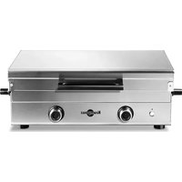
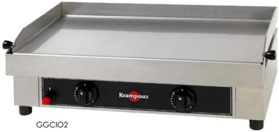
Exterior view of a Krampouz electric grater with two side control knobs (no text or symbols on the device itself)
AUTOMATIC
CONTROL SYSTEM ^2
natural_image
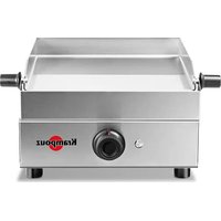
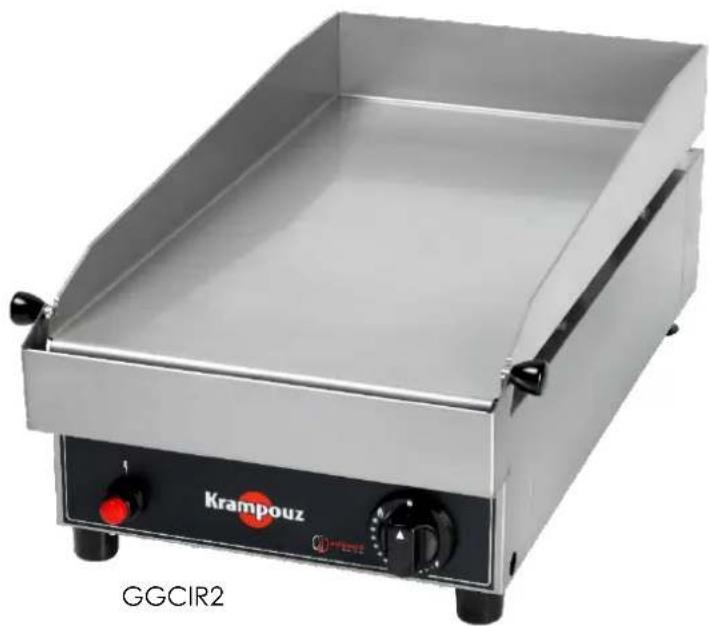
Exterior view of a Krampouz gas grater with control knobs and a label 'GGCIR2' (no other text or symbols visible)
AUTOMATIC
CONTROL SYSTEM
text_image
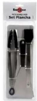
Kremour FACE SPRESSER Set PlanchaSet plancha ASP1
Plancha set ASP1

Pinceau silicone APS2
Silicon brush ASP2
| Modèle Model | Dimensions Dimensions | Surface de cuisson Cooking surface | Puissance Power | Poids Weight |
| GGCIO2 | 700 x 415 x 230 mm | 640 x 340 mm | 2 x 2.25 kW | 19 kg |
| GGCIR2 | 400 x 690 x 266 mm | 340 x 640 mm | 4.5 kW | 20 kg |
natural_image
Technical line drawing of a mechanical or electronic component with multiple slots and mounting features (no text or symbols)- GGCIO2 :
text_image
Technical diagram of a pipe fitting with labeled components A and B, showing pipe connection and valve assembly.CHANGEMENT DU RECIPIENT DE GAZ
Thank you for purchasing one of our products. Although it is very easy to use, we recommend that you read these instructions carefully, as they provide installation and operating information for optimum results.
Receipt and unpacking:
Any damage due to shipping must be reported to the carrier by registered letter with return receipt, within 24 hours of receipt of the appliance. You must also mention your reserves on the carrier's receipt and accurately describe damage found on delivery.
General instructions
When using gas appliances, always take basic safety precautions.
Read all instructions carefully.
- This appliance is for professional use of qualified, trained personnel who have read the instructions.
- The installation, maintenance and adjustment operations (injector changes) of this product must be performed by installation engineers or technicians qualified for gas appliances.
- This appliance was designed to operate with butane or propane gas cylinders, but also from a natural gas supply.
- Appliances running with natural gas must be laid on a fixed work top. Do not use trolleys.
- The appliance must never be left unattended when in use.
- The surfaces are likely to become hot when in use.
- Choose a base made from stainless steel or any other flame-proof material which meets hygiene standards.
- Shelter this product from wind when in use.
- Never switch on the appliance when there is a strong wind and never place it in a draught.
- Place the appliance on a stable, dry surface, slightly away from the edge and at least 1 m away from any combustible material, item or wall sensitive to heat.
- Do not use the appliance for any purpose besides its intended one.
- Using accessories not recommended by the appliance's manufacturer may cause accidents.
- Parts protected by the manufacturer or its assignee must not be handled by the user.
- Do not move the appliance while operating it.
- Do not touch hot surfaces.
- Do not handle the appliance when hot.
- Leave the appliance to cool down before handling or cleaning it.
- Do not clean the appliance with a high or low pressure water spray.
- Do not use chlorinated products to clean stainless steel.
- If you smell gas, close all valves.
- Never use a leaky appliance.
- Keep this appliance away from flammable materials during use.
- Modifying the appliance may be dangerous.
-
Do not use an adjustable pressure regulator.
-
The bottom of the appliance must stay ventilated to allow proper air flow to the burner.
- Do not obstruct the frame's ventilation inlets and the ventilation holes in the bottom plate under the frame.
- Caution: Do not insert aluminium foil or any other material or object between the plate and the frame (ventilation zone).
- In the event of failure, inspection and repairs must be performed by an approved technician.
- Warning: do not use this appliance with charcoal or any other power source than the one for which it is intended (gas power).
- When not used, close the valve of the gas cylinder or the wall-mounted valve for natural gas.
- Recommended height of the cooking plate: 85 to 95 cm from the ground for a good operating position.
- Check the condition of the hose (NF or EC). Change it immediately if in doubt.
- Check the expiry date of the hose.
- Do not twist the hose and keep it away from any source of heat.
- When the appliance is not in use, store it somewhere dry.
- We recommend that you keep the original packaging for storing the appliance.
- The film on the stainless steel protects it from scratches. It is vital to mandatory it before first use.
- - Clean the plate before first use.
KEEP THESE INSTRUCTIONS
Technical description
SPECIFICATIONS
- Stainless steel frame and cooking plate
- Food-grade certified plate
- Edges on 3 sides
- Removable, disposable cooking waste collector
- One heating zone (GGCIR2) or two heating zones (GGCIO2)
- Thermostat(s) adjustable up to 300°C with a thermocouple safety system (automatic gas cut-out if no flame)
- Electronic spark ignition (LR6 battery)
- Butane/propane and natural gas supply
- 2 adjustable feet to the rear
- Power:
○ GGCIR2: 4.5 kW
○ GGCIO2: 2 × 2.25 kW
This appliance complies with the CE European Directives.
SPECIFICATIONS
Refer to the information plate affixed to the appliance to find out the category of the appliance according to the country of destination.
Plancha reference GGCIO2
| Index of categories | Type of gas and pressure | Country | Opening of the air collars | Injector marking | By-pass marks | Rated flow | Rated consumption | Reduced flow | |
| LPG | 3+ | G30/G31 28-30/37 mbar | BE, CH, ES, FR, GB, GR, IT, PT, IE | 4 mm | 80 | 55 (tight) | 4500 W | G30: 327 g/h G31: 321 g/h | 2000 W |
| 3B/P | G30/G31 50 mbar | DE | 4 mm | 72 | 50 (tight) | 4500 W | G30: 327 g/h G31: 321 g/h | 2000 W | |
| Natural gas | 2E+ | G20/G25 20/25 mbar | BE, FR | 1 mm | 120 | Adjustment of the bypass: loosened by one turn | 4500 W | G20: 476 g/h G25: 553 g/h | 2000 W |
| 2H | G20 20 mbar | CH, ES, GB, IT, PT, IE, GR | 1 mm | 120 | Adjustment of the bypass: loosened by one turn | 4500 W | 476 g/h | 2000 W | |
| 2E | G20 20 mbar | DE | 1 mm | 120 | Adjustment of the bypass: loosened by one turn | 4500 W | 476 g/h | 2000 W |
Plancha reference GGCIR2
| Category index | Type of gas and pressure | Country | Opening of the air collars | Injector marking | By-pass marks | Rated power | Rated consumption | Reduced power | |
| LPG | I3 + | Butane/Propane G30/G31 28-30/37 mbars | BE, CH, CY, CZ, ES, FR, GB, GR, IE, IT, LT, LU, PT, SI, SK | 5 mm | 110 | 80 (locked) | 4.5 kW | G30:355 g/hr G31: 350 g/hr | 2.5 kW |
| I3B/P | Butane/Propane G30/G31 30 mbars | DK, EE, FI, HU, NL, NO, PL, RO, SE, SI | 5 mm | 110 | 80 (locked) | 4.5 kW | G30:355 g/h G31: 350 g/hr | 2.5 kW | |
| I3B/P | Butane/Propane G30/G31 50 mbars | AT, DE | 5 mm | 95 | 75 (locked) | 4.5 kW | G30:355 g/h G31: 350 g/hr | 2.25 kW | |
| Natural gas | I2E + | G20/G25 20-25 mbar | BE, FR | 3 mm | 168 | 80 By-pass setting: Unlock with a turn and a quarter | 4.5 kW | G20: 476 l/hr G25: 553 l/h | 2.3 kW |
| I2H | G20 20 mbars | AT, CH, CY, CZ, DK, EE, ES, FI, GB, GR, HU, IE, IT, LT, NO, PT, RO, SE, SI, SK | 3 mm | 168 | 80 By-pass setting: Unlock with a turn and a quarter | 4.5 kW | G20: 476 l/h | 2.3 kW | |
| I2E | G20 20 mbar | DE, LU | 3 mm | 168 | 80 By-pass setting: Unlock with a turn and a quarter | 4.5 kW | G20: 476 l/h | 2.3 kW |
Typ A1 appliance: without fan. When used indoors, an open space above the plate is required near an extractor system, in line with the regulations of the country. Renewing the combustion air supply air at least 15 m^3/hr is required.
GAS CONNECTION
The configuration of the appliance supply is indicated by a marking (X) on the information plate affixed to the back of the appliance.
To change the gas configuration of your appliance, refer to the “Adjustment” chapter (page 28).
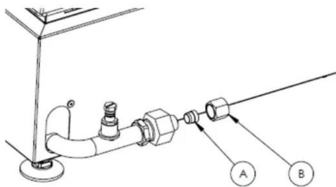
- The plancha must be connected using the connection on the front of the appliance (GGCIR2) or the back of the appliance (GGCIO2), using a flexible pipe which meets the standards below for natural gas and the family 3 gases Butane/Propane.
- Check the connection sealing using soapy water.
- Never test leak-tightness using a flame.
- Do not use a butt teat.
- The appliance must be installed at least 10 cm away from any wall or enclosure, and it must not come into contact with any object or enclosure.
Connection for using your appliance in category I3+
Butane
For Butane G30 gas, use a NF 28 mbar safety pressure regulator
- NFD36-125 metallic hose (Life: no use limit) / length: 1 m
- NFD36-112 hose (Life: 10 years) / length: 1 m
Propane
For Propane G31 gas, use a NF 37 mbar safety pressure regulator
- NFD36-125 metallic hose (Life: no use limit) / length: 1 m
- NFD36-112 hose (Life: 10 years) / length: 1 m
Connection for using your appliance in category I2E+
Natural gas
For Natural gas G20 and G25
- NFD36-121 metallic hose (Life: no use limit)
- NFD36-103 hose (Life: 10 years)
Check that the hose is not subjected to stress or twisting. Check its condition. Change it immediately if it seems cracked or slightly burnt.
Specific connection
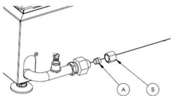
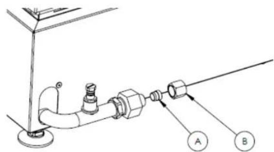
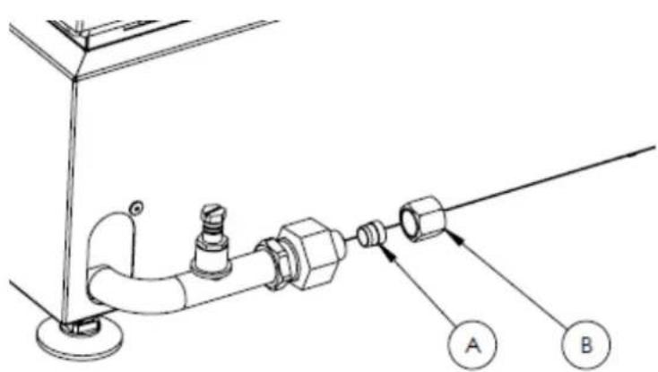
In Germany, use the suitable connection below, which is supplied with your appliance:
- GGCIR2:
natural_image
Technical line drawing of a rectangular electronic enclosure with slots and mounting feet (no text or symbols)- GGCIO2:
text_image
Technical diagram showing pipe connection with labeled points A and B, likely illustrating a mechanical or fluid system setup.CHANGING THE GAS CYLINDER
Always change the gas cylinder with the control levers and the gas cylinder valve closed, in a well-ventilated area, away from any source of heat (cigarette, electrical appliances, etc.).
We recommend using commercial 6 kg or 13 kg butane or propane gas cylinders using an appropriate pressure regulator.
Whenever you change the gas cylinder, perform a leak-tightness test.
STARTING UP
Connect the appliance to the supply source using a gas pipe in line with currently enforced European standards and requirements.
Use a hose meeting the normative specifications of your country.
Check that your pipe or hose is not in contact with parts of the appliance which are likely to become hot.
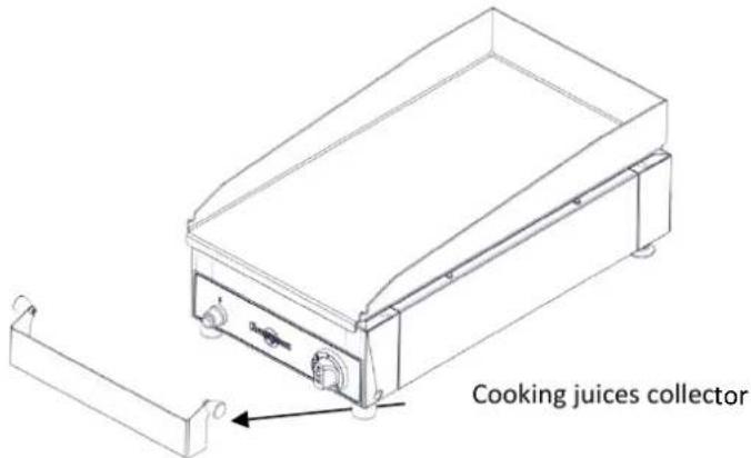
The container supplied with your appliance is for recovering cooking juices, and must be handled when the appliance is cold.
KRAMPOUZ cannot accept liability for damage caused to objects or persons resulting from improper installation or use of the appliance.
text_image
Cooking juices collector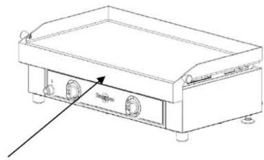
natural_image
Line drawing of a rectangular electronic device with two side buttons and a central control panel (no text or symbols)When using the plancha, the cooking juices collector must be fitted in the right place. (Risk of damaging the handles)
Use
This appliance is for professional use of qualified, trained personnel who have read the instructions.
IGNITION
- The appliance is ready for operation. Check that the gas inlet is open. Shut off the appliance's gas inlet immediately if you smell gas. If the smell persists, check the connection and pressure screw and contact your qualified gas installation engineer. (See figure 1 page 65)
- For the first ignition after installation, push the lever, set it to the high flame position and hold it for 5 seconds to bleed the air from the gas pipe to the burner. Then release the lever.
- Open the valve by turning the lever on the left until it is in the high flame position (drawing shown on the lever).
- Activate the spark ignition and then push the lever in this position to obtain full burner ignition.
- Maintain pressure on the lever for 5 to 10 seconds to engage the thermocouple safety system.
- Then release the lever and allow the burner to heat the cooking plate to the appropriate temperature.
- Your appliance is ready to be used.
COMMENTS
The first time it is used, you may see some smoke and smell some odours coming from the appliance.
Featuring an “Automatic control system”, this gas plancha is for precision cooking and maximum response to temperature variations. Its design guarantees even heat distribution over the entire surface as well as a 30% reduction in energy consumption.

AUTOMATIC
CONTROL SYSTEM®
The appliance features a thermostat for controlling the cooking temperature. During preheating, the burners emit high flames until the set temperature is reached. Once the set temperature is reached, the flames are regulated automatically to maintain the same temperature (variation from high to low flame, and vice versa). Therefore the plancha maintains this temperature by itself throughout the cooking process.
COOKING
Preheat the plancha to the cooking temperature you require. If necessary, apply oil evenly using a brush. Place the food on the plate. With practice you will get to know the temperatures that are best suited to the foods being cooked, according to their thickness, texture and your taste. The times indicated below are for information only.
| Food | Cooking time | |
| FISH AND SEAFOOD | Fish kebab | 15 min |
| Prawns | 15 min | |
| Scallops | 15 min | |
| Salmon | 15 min | |
| Monkfish or cod cheek | 15 min | |
| Coquilles St Jacques | 15 min | |
| Cuttlefish, squid or octopus | 15 min | |
| MEAT AND POULTRY | Rare T-bone steak | about 5 min on each side |
| Medium T-bone steak | about 15 min on each side | |
| Rare steak | about 1 min on each side | |
| Medium steak | about 3 min on each side | |
| Shredded pork or veal | 20 min | |
| Shredded rabbit or chicken | 30 min | |
| Duck fillets | 1 to 3 min on each side | |
| Duck breasts | 10 min on the skin side, then 5 min on the other side | |
| Beef kebabs | 5 to 10 min | |
| Lamb chops or kebabs | 5 to 10 min | |
| VEGETABLES | Mushrooms/Onions/Courgettes/Carrots/Tomatoes/Vegetable kebabs/Peppers, etc. | 10 to 15 min |
| FRUIT | Bananas/Apples/Pears/Peaches/Oranges/Pineapple, etc. | 1 to 3 min |
ADVICE
To avoid making deep scratches on the plate, do not cut your food directly on it.
Do not leave kitchen utensils on the plancha, such as cutlery, wooden spoons, plastic utensils, etc.
Do not cook at too high a temperature as this may char the plate and make it difficult to clean.
The plancha can be used for keeping food warm at the end of cooking by adjusting the lever to the low flame.
For all of our recommendations for use and recipes, go to our website at www.krampouz.com.
SWITCHING OFF THE PLANCHA
- After use, switch off your appliance by placing the lever or levers vertically to the large full circle position.
- Close the valve on the gas cylinder
- Disconnect the supply hose from the appliance and store it in a dry, well-ventilated place. The gas cylinder must also be stored in a dry, well-ventilated place, away from any source of heat.
Adjustments
When changing the type of gas, always change the injectors (see instructions in the table on page 16).
CHANGING THE INJECTORS
On an installed appliance, before changing the injectors and making the new adjustments, close the valve on the supply pipe or gas cylinder.
Perform the following operations:
- Close the valve on the supply pipe or gas cylinder.
GGCIR2
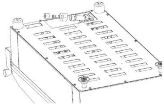
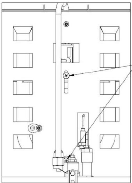
- Turn the appliance, remove the galvanised steel plate and unscrew both screws on the injector support (see figure 2 page 66-67)
- Remove the injector from the burner hole.
- Unscrew the injector with a size 7 wrench, then take the transformation bag (injector bag).
-
Change the injector and its seal, as indicated in the table for the different supply types (table on page 27, injector marking and air collar opening).
-
Reposition the injector in the burner hole and tighten both injector support screws.
- Clean and tighten the appliance's protection. We recommend that you record the new configuration on the appliance's information plate and delete the old one.
- Place the changed injector in the conversion bag and store it carefully. Then refer to the start-up procedure.
GGCIO2
- Turn the appliance, and remove the galvanised steel plate.
- Push the burner away from the valve.
- Unscrew the injector with a size 10 wrench and its bracket with a size 13 wrench. Then take the conversion set (set of injectors), as shown in the figure below). (see figure 3 on page 66-67)
- Change the injector and its seal, as per the instructions in the correspondence table of the different types of supply (table on page 27).
- Return the burner to its initial position and then tighten the two screws to lock the burner.
- Clean and tighten the appliance's protection. We recommend that you record the new configuration on the appliance's information plate and delete the old one.
- Place the changed injector in the conversion bag and store it carefully. Then refer to the start-up procedure.
IDLE FLAME SETTING
When the appliances are set to Butane/Propane gas, the idle screw is turned as far to the right as possible.
When switching from Butane/Propane gas to natural gas, loosen this screw until you obtain a good idle flame setting (see the table on page 27). The idle flame is set properly when the flame is not extinguished when passing quickly from the maximum to the minimum positions.
Set the idle flame with the cooking plate installed and fastened:
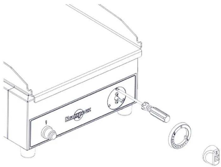
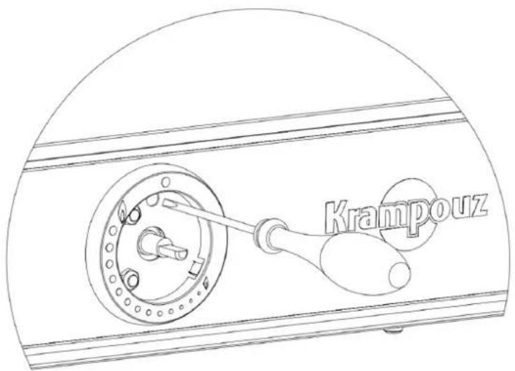
- Move the lever, pulling it towards you, and remove the ring.
- Use a small screwdriver to access the adjustment screw located on the periphery of the thermostat axis. Turn the idle screw through one anticlockwise revolution and refit the lever (see figure 4 on page 68).
- Switch the plancha on in the high flame position for 5 minutes
- Set the lever to the low flame position
- While looking at the flame under the plate, loosen to increase the idle flame and tighten to reduce it (see table page 16).
- Replace the lever and the ring.
SETTING THE AIR COLLAR
GGCIR2
When the appliances are set for Butane/Propane, the air collar is set to 5 mm opening for pressures of 28-30 mbars (butane) and 37 mbars (propane) or 5 mm for 50 mbars (butane/propane).
When switching from Butane/Propane gas to natural gas, the opening of the air collar must be modified. To do this, loosen the screw on the air collar using a screwdriver and then set the opening to 3 mm. Once set, tighten the screw (see figure 5 on page 69).
GGCIO2
When the appliances are set to Butane/Propane gas, the air collar is opened 4 mm.
When switching from Butane/Propane gas to natural gas, the opening of the air collar must be modified. To do this, loosen the air collar screw with a screwdriver and then set the opening at 1 mm (see figure on 5 page 69). Once set, tighten the screw.
SETTING THE SPARK IGNITER AND SAFETY THERMOCOUPLE
To ensure that the burner ignites properly, the spark igniter must always be positioned 5 mm from the burner.
To ensure that the thermocouple safety system works properly, the end must be in the flame and always positioned 2 mm from the burner (see figures 6 and 7 on pages 70 and 71).
Maintenance and Cleaning
THE PLATE
Upon delivery, the ferritic stainless steel plate of the plancha will have a matt appearance. Scratches and black spots will soon appear with normal use of the appliance. All of these scratches and spots will soon blend and the plate will have a patinated, brushed appearance which will not change further over time. This will not affect cooking in any way.
To clean the plancha switch it off and close the gas valve. It is easier if the plancha is still lukewarm. Do not burn yourself.
Use a rigid spatula to remove the bulk of the juices adhering to the cooking plate by pushing them towards the cooking waste collector.
Then thoroughly moisten the cooking plate to water down the remaining juices (using a wet sponge or dropping ice cubes onto it). Leave for a few minutes.
Use the rigid spatula to remove the remaining watered down juices by pushing them towards the cooking waste collector.
Finish cleaning with an abrasive and then a soft sponge.
Pour white vinegar onto the plate to remove residual odours and flavours.
After cooking salty preparations, the cooking plate must be cleaned promptly (otherwise the salt will corrode the plate). Do not use chlorinated products as these may also cause corrosion.
FRAME
The stainless steel frame should be cleaned with a slightly moist sponge.
This collects the cooking waste. It must be handled once the appliance is cool, and then emptied and cleaned before the next use.
BURNER(S)
Periodically check the condition of the flame holes on the burners and the air collar(s), which may become obstructed by insect nests, cobwebs or dirt.
If the flame holes are clogged, brush the branches with a hard bristle brush. To clean the air collar(s), we do NOT recommend using metal objects, as they are likely to alter the technical specifications of the burner(s).
We therefore recommend that you blow into the air collar. The burner and air collar may be accessed by removing the appliance's metal plate (see figures 2 and 3 p 66-67).
ELECTRONIC IGNITION
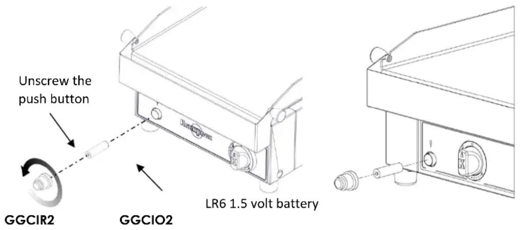
It is supplied with a LR6 battery (1.5 Volts). To change the battery, refer to the diagram below.
text_image
Unscrew the push button GGCIR2 GGCIO2 LR6 1.5 volt batteryPackaging must be discarded in line with current regulations
This appliance comes with one year's warranty for spare parts.
We do our very best to ensure that our appliances reach you in perfect working order. If you find a fault when unpacking, please tell the store within 48 hours.
If during this period, you find that it does not work properly, please contact your retailer.
The following are excluded from the guarantee:
1-Fair wear and tear of the product which does not affect appliance operation (scratches, superficial corrosion, black spots, knocks, colour changes, etc.).
2-Damage resulting from an abnormal event or misuse, product modification or failure to observe the indications contained in the operating instructions.
3-Damage resulting from a fall or knock.
Please send us your suggestions.
KRAMPOUZ cannot accept any liability for damage caused to objects or persons resulting from incorrect appliance installation or use.
Werter Kunde,
natural_image
Technical line drawing of a mechanical enclosure with multiple slots and mounting feet (no text or symbols)GGCIO2:
text_image
Technical diagram showing pipe connection with labeled components A and B, likely for plumbing or piping installation.natural_image
Line drawing of a portable electric stove or grating unit with two side-mounted fans and a control panel (no text or symbols)natural_image
Technical line drawing of a mechanical enclosure or panel with multiple ports and internal compartments (no text or symbols)GGCIO2:
text_image
Technical diagram showing pipe connection with labeled components A and B, likely illustrating a fluid or piping system.natural_image
Technical line drawing of an electrical enclosure with internal components and mounting holes (no text or symbols)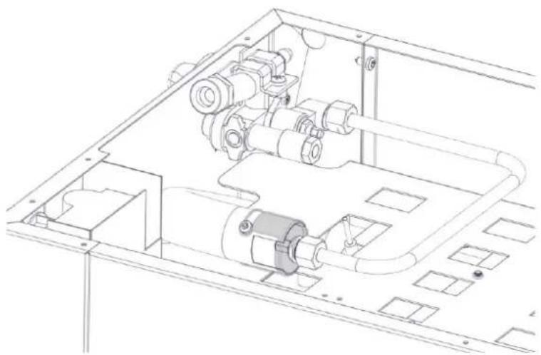
natural_image
Technical line drawing of an internal mechanical assembly (no text or symbols)FIGURES 2 AND 3 – SETTINGS chapter, INJECTOR REPLACEMENT paragraph
natural_image
Technical line drawing of a mechanical or fluidic device with no visible text, numbers, or symbols.Vue de dessus / Top view Ansicht von oben / Vista superior
natural_image
Technical line drawing of a mechanical assembly with mounting holes and a vertical shaft (no text or symbols)Vue de dessous / Bottom view Ansicht von unten / Vista inferior
Burner locking screws
natural_image
Technical line drawing of an electronic device chassis with multiple compartments and control knobs (no text or symbols)FIGURE 4 – Chapitre RÉGLAGES, paragraphe RALENTI
FIGURE 4 – SETTINGS chapter, IDLE FLAME paragraph ABBILDUNG 4 – Kapitel EINSTELLUNGEN, Paragraf LEERLAUF ILUSTRACIÓN 4 – Capítulo AJUSTES, párrafo FLUJO MÍNIMO
GGCIR2
natural_image
Technical line drawing of a Kroupouz industrial machine with attached components (no text or symbols)GGCIO2
text_image
KrampouzFIGURE 5 – SETTINGS chapter, AIR COLLAR paragraph
FIGURE 7 – SETTINGS chapter, THERMOCOUPLE SAFETY paragraph
Thermocouple safety system