KGRDG.251314 - Grill plate KRAMPOUZ - Free user manual and instructions
Find the device manual for free KGRDG.251314 KRAMPOUZ in PDF.
| Brand | Krampouz |
| Model | KGRDG.251314 |
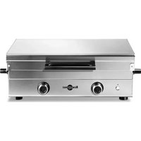
| Product type | Professional gas griddle plate |
| Usage | Professional use only |
| Dimensions (W x D x H) | 699 x 433 x 298 mm |
| Cooking surface dimensions (W x D) | 646 x 354 mm |
| Weight | 22 kg |
| Power supply | Natural gas (factory) or propane (conversion kit included) |
| Total power | 13648 BTU/h (4 kW) |
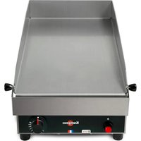
| Burners | 2 U-shaped burners |
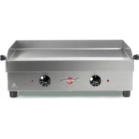
| Cooking zones | 2 independent zones with adjustable thermostat |
| Temperature range | Up to 300 °C (570 °F) |
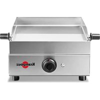
| Ignition | Battery-powered electronic (LR6 1.5 V battery) |
| Plate material | Stainless steel |
| Drip tray | Included, removable for cleaning |
| Safety | Safety thermocouple, automatic gas shut-off |
| Maintenance | Daily cleaning with non-abrasive cloth and vinegar |
| Spare parts | Orifices, battery, thermocouple, spark plug |
| Repairability | Maintenance by qualified personnel only |
| Warranty | 1 year parts and labor (under conditions) |
Frequently Asked Questions - KGRDG.251314 KRAMPOUZ
User questions about KGRDG.251314 KRAMPOUZ
0 question about this device. Answer the ones you know or ask your own.
Ask a new question about this device
Download the instructions for your Grill plate in PDF format for free! Find your manual KGRDG.251314 - KRAMPOUZ and take your electronic device back in hand. On this page are published all the documents necessary for the use of your device. KGRDG.251314 by KRAMPOUZ.
USER MANUAL KGRDG.251314 KRAMPOUZ
Gas Griddle Plancha Gaz
KGRDG Series/Série
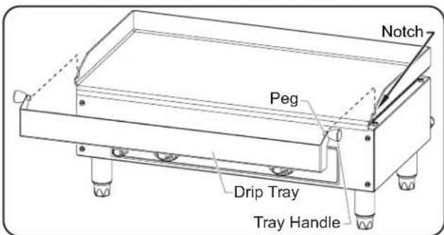
natural_image
Line drawing of a portable grating or pressure vessel with control knobs and mounting feet (no text or symbols)WARNING
Do not operate this equipment unless you have read and understood the contents of this manual! Failure to follow the instructions contained in this manual may result in serious injury or death. This manual contains important safety information concerning the maintenance, use, and operation of this product. If you're unable to understand the contents of this manual, please bring it to the attention of your supervisor. Keep this manual in a safe location for future reference.
English = p 2
ADVERTENCIA
Important Owner Information....2
Introduction....2
Important Safety Information....3
Model Description 4
Model Designation 4
Specifications ....5
Rating Charts....5
Dimensions....5
Installation....6
General....6
Connecting the Gas Supply....7
Operation....8
General....8
Control Panel....8
Lighting the Burners 8
Operating the Unit 9
Maintenance....10
General....10
Daily Cleaning 10
Converting Between Fuels 11
Changing the Ignition Battery 12
Safety Thermocouple 12
Ignition Spark Plug 12
Troubleshooting Guide 13
Limited Warranty 14
Authorized Parts Distributors ....Back Cover
IMPORTANT OWNER INFORMATION
Record the model number, serial number, voltage, and purchase date of the unit in the spaces below (specification label located on the back the unit). Please have this information available when calling Hatco for service assistance.
Model No. ____
Serial No.
Voltage
Date of Purchase
Register your unit!
Completing online warranty registration will prevent delay in obtaining warranty coverage. Access the Hatco website at www.hatcocorp.com, select the Support pull-down menu, and click on "Warranty".
Business
Hours: 7:00 AM to 5:00 PM Monday–Friday,
Central Time (CT)
(Summer Hours — June to September:
7:00 AM to 5:00 PM Monday–Thursday
7:00 AM to 4:00 PM Friday)
Telephone: 800-558-0607; 414-671-6350
E-mail: support@hatcocorp.com

24 Hour 7 Day Parts and Service Assistance available in the United States and Canada by calling 800-558-0607.
Additional information can be found by visiting our web site at www.hatcocorp.com.
INTRODUCTION
Gas Griddles cook a wide variety of food product in a small footprint for commercial kitchens. Two cooking zones with dedicated controls enable operators to cook food product with different temperature requirements on the same griddle surface. Two U-shaped burners provide exceptional heat distribution over the entire griddle for even and fast cooking.
Gas Griddles are products of extensive research and field testing. The materials used were selected for maximum durability, attractive appearance, and optimum performance. Every unit is inspected and tested thoroughly prior to shipment.
This manual provides installation, safety, and operating instructions for Gas Griddles. Hatco recommends all installation, operating, and safety instructions appearing in this manual be read prior to installation or operation of a unit.
Safety information that appears in this manual is identified by the following signal word panels:

WARNING indicates a hazardous situation which, if not avoided, could result in death or serious injury.

CAUTION indicates a hazardous situation which, if not avoided, could result in minor or moderate injury.
NOTICE
NOTICE is used to address practices not related to personal injury.

Read the following important safety information before using this equipment to avoid serious injury or death and to avoid damage to equipment or property.
WARNING
FIRE OR EXPLOSION HAZARD:
- This unit is designed to be used with propane or natural gas. Contact a qualified installer to determine and perform proper gas connections.
- Unit must be installed by qualified, trained gas equipment installers. Installation must conform to all local plumbing and gasfitting codes. Installation by unqualified personnel will void the unit warranty and may lead to fire or explosion causing property damage, personal injury, or death. Check with local plumbing inspectors for proper procedures and codes.
- In the absence of local plumbing and gasfitting codes, installation must conform with National Fuel Gas Code ANSI Z223.1/NFPA 54 or National Gas and Propane Installation Code CSA B149.1, as applicable.
- The gas used with this unit must be the type specified on the specification plate on this unit. To avoid personal injury or damage to the unit, never use any other than the specified gas.
- Unit must be connected to gas supply using a moveable gas connector that complies with current and local standards and codes.
- Inspect moveable gas connector regularly. Replace immediately if any signs of wear are present.
- Verify moveable gas connector has not exceeded its expiration date. Replace immediately if expired.
- Do not twist moveable gas connector.
- Keep moveable gas connector away from hot appliances and surfaces.
- The unit and its gas connections must be leak tested before placing unit in operation. Use soapy water or commercially available fluid for leak test. DO NOT use open flame to test for leaks.
- The unit and its individual gas shut-off valve must be disconnected and isolated from the gas supply piping system during any pressure testing of the system at test pressures in excess of 1/2 psi (3.5 kPa.).
- This unit must be isolated from the gas supply piping system by closing its individual gas shut-off valve during any pressure testing of gas supply piping system at test pressures equal to or less than 1/2 psi (3.5 kPa).
- Locate unit a minimum of 39" (100 cm) from combustible surfaces. If safe distances are not maintained, discoloration or combustion could occur.
- Do not install unit above or around combustible surfaces. Discoloration or combustion could occur. Unit must be installed in non-combustible surroundings only.
- Do not obstruct air ventilation openings on unit. Unit combustion or malfunction may occur.
- Do not store or use gasoline or other flammable vapors or liquids in the vicinity of this or any other appliance.
WARNING
FIRE OR EXPLOSION HAZARD:
- If the information in these instructions is not followed exactly, fire or explosion may result causing property damage, personal injury, or death
- This unit must be serviced by qualified personnel only. Service by unqualified personnel may lead to explosion or burn.
- Use only Genuine Hatco Replacement Parts when service is required. Failure to use Genuine Hatco Replacement Parts will void all warranties and may subject operators of the equipment to hazardous conditions. Genuine Hatco Replacement Parts are specified to operate safely in the environments in which they are used. Some aftermarket or generic replacement parts do not have the characteristics that will allow them to operate safely in Hatco equipment.
Unit must be installed in location with sufficient ventilation to prevent buildup of unsafe levels of noxious fumes.
Unit must be installed on a fixed worktop. Do not install on a moveable cart.
Turn Temperature Controls to OFF position, close gas shut-off valve, and allow unit to cool before performing any cleaning, adjustments, or maintenance.
Unit is not weatherproof.
Do not steam clean or use excessive water on unit.
This unit is not "jet-proof" construction. Do not use jet-clean spray to clean this unit.
DO NOT submerge or saturate with water. Unit is not waterproof. Do not operate if unit has been submerged or saturated with water.
Do not allow liquids to spill into unit.
Make sure all operators have been instructed on the safe and proper use of the unit.
This unit is not intended for use by children or persons with reduced physical, sensory, or mental capabilities. Ensure proper supervision of children and keep them away from the unit.
Never leave unit unattended during use.
Always turn off individual gas shut-off valve when unit is not in use.
Do not make any modifications to unit. Personal injury and damage to unit may occur.
Do not use unit for any purpose other than for which it is designed.
This unit has no "user-serviceable" parts. If service is required on this unit, contact an Authorized Hatco Service Agent or contact the Hatco Service Department at 800-558-0607 or 414-671-6350.
CAUTION
BURN HAZARD:
- Some exterior surfaces on unit will get hot. Avoid unnecessary contact with unit.
- Do not come in contact with griddle during operation. Griddle is very hot.
- Allow unit to cool before performing any cleaning, adjustments, or maintenance.
Do not operate unit without installing supplied legs.
Never operate unit without drip tray installed.
Locate unit at proper counter height in an area that is convenient for use. Location should be level and strong enough to support weight of unit and contents.
NOTICE
Allow adequate ventilation around base of unit for proper air supply to gas burner.
Do not locate unit in an area subject to excessive temperatures or grease from grills, fryers, etc. Excessive temperatures and grease could cause damage to unit.
NOTICE
Damage to any countertop material caused by heat generated from this equipment is not covered under the Hatco warranty. Contact manufacturer of countertop material for application information.
For frame of unit, use non-abrasive cleaners and cloths only. Abrasive cleaners and cloths could scratch finish of unit, marring its appearance and making it susceptible to soil accumulation.
Do not use harsh chemicals such as bleach, cleaners containing bleach, or oven cleaners to clean this unit.
This unit is intended for commercial use only—NOT for household use.
Clean unit daily to avoid malfunctions and maintain sanitary operation.
MODEL DESCRIPTION
The Gas Griddle consists of an easy-to-clean, stainless steel frame and a rectangular, stainless steel griddle. The griddle is divided into two, individually-controlled cooking zones. The controls include an adjustable Temperature Control for each zone and an electronic ignition button.
All Gas Griddles come from the factory setup for use with natural gas. Conversion components are included to convert the units for use with propane. Refer to the MAINTENANCE section of this manual, and contact an Authorized Service Agent or Hatco for assistance.
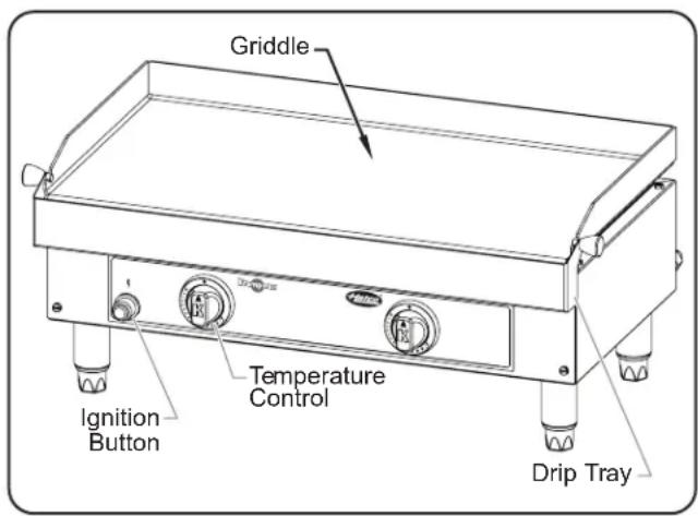
text_image
Griddle Ignition Button Temperature Control Drip TrayModel KGRDG-2513
MODEL DESIGNATION
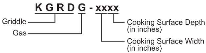
text_image
K G R D G - xxxx Griddle Gas Cooking Surface Depth (in inches) Cooking Surface Width (in inches)Ratings Chart—Propane
| Model | Burner Power (BTU/Hour) | Burner Power (Kilowatts) | Manifold Pressure | Pressure Regulator Factory Setpoint | Burner Orifice Size Unit | Weight |
| KGRDG-2513 | 13648 | 4 | 10.9 In WC | 10.9 In WC | 85 μm | 49 lbs. (22 kg) |
Ratings Chart—Natural Gas
| Model | Burner Power (BTU/Hour) | Burner Power (Kilowatts) | Manifold Pressure | Pressure Regulator Factory Setpoint | Burner Orifice Size Unit | Weight |
| KGRDG-2513 | 13648 | 4 | 7 In WC | 7 In WC | 120 μm | 49 lbs. (22 kg) |
Dimensions
| Model | Width (A) | Depth (B) | Height (C) | Footprint Width (D) | Footprint Depth (E) | Cooking Surface Width (F) | Cooking Surface Depth (G) |
| KGRDG-2513 27 | -9/16" (699 mm) | 17-1/16" (433 mm) | 11-3/4" (298 mm) | 24-1/16" (611 mm) | 11-1/2" (291 mm) | 25-7/16" (646 mm) | 13-15/16" (354 mm) |
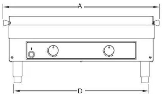
text_image
A DFront View
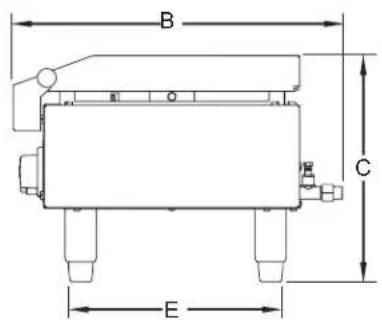
text_image
B C ESide View
text_image
F GTop View
General
Gas Griddles are shipped with most components installed and ready for operation. Care should be taken when unpacking the shipping carton to avoid damage to the unit. The following installation procedure must be performed before operating the unit.
WARNING
FIRE OR EXPLOSION HAZARD:
- This unit is designed to be used with propane or natural gas. Contact a qualified installer to determine and perform proper gas connections.
- Unit must be installed by qualified, trained gas equipment installers. Installation must conform to all local plumbing and gasfitting codes. Installation by unqualified personnel will void the unit warranty and may lead to fire or explosion causing property damage, personal injury, or death. Check with local plumbing inspectors for proper procedures and codes.
- In the absence of local plumbing and gasfitting codes, installation must conform with National Fuel Gas Code ANSI Z223.1/NFPA 54 or National Gas and Propane Installation Code CSA B149.1, as applicable.
- The gas used with this unit must be the type specified on the specification plate on this unit. To avoid personal injury or damage to the unit, never use any other than the specified gas.
- Unit must be connected to gas supply using a moveable gas connector that complies with current and local standards and codes.
- Do not twist moveable gas connector.
- Keep moveable gas connector away from hot appliances and surfaces.
- The unit and its gas connections must be leak tested before placing unit in operation. Use soapy water or commercially available fluid for leak test. DO NOT use open flame to test for leaks.
- Locate unit a minimum of 39" (100 cm) from combustible surfaces. If safe distances are not maintained, discoloration or combustion could occur.
- Do not install unit above or around combustible surfaces. Discoloration or combustion could occur. Unit must be installed in non-combustible surroundings only.
- Do not obstruct air ventilation openings on unit. Unit combustion or malfunction may occur.
- If the information in these instructions is not followed exactly, fire or explosion may result causing property damage, personal injury, or death
Unit must be installed in location with sufficient ventilation to prevent buildup of unsafe levels of noxious fumes.
Unit must be installed on a fixed worktop. Do not install on a moveable cart.
Unit is not weatherproof.
- Inspect the shipping carton for obvious signs of transit damage. If damaged, inform the freight company immediately. CAUTION! Stop! Do not attempt to use unit if damaged. Contact Hatco for assistance.
- Remove the unit and any loose components/accessories from the shipping carton. The following loose components are included in every Gas Griddle:
- Legs
- Drip Tray
• Propane Conversion Components - Pressure Regulator
• Gas Shut-Off Valve
NOTE: To prevent delay in obtaining warranty coverage, complete online warranty registration. See the IMPORTANT OWNER INFORMATION section for details.
- Remove tape and protective packaging from all surfaces of the unit.
- Make sure to remove all protective film from the stainless steel surfaces.
- Inspect the unit for freight damage such as dents in housing or broken knobs. If damaged, inform the freight company immediately.
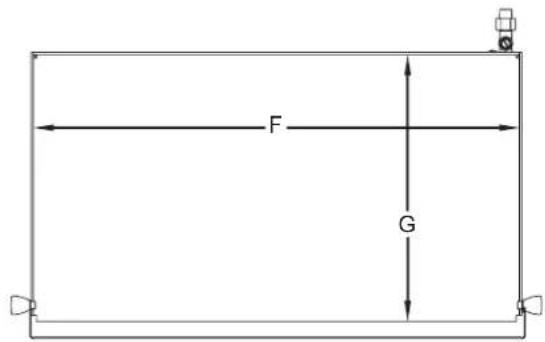
- Install the included legs.
a. Carefully tip the unit backwards and rest it on top of cardboard on a flat surface.
b. At each corner, thread a leg into the bottom of the unit. Hand-tighten until snug. Do not over-tighten.
c. Return the unit to the upright position.
NOTE: The feet on the legs are adjustable for leveling the unit. Make leveling adjustments once the unit is placed in its final position.
text_image
Leg Adjustable FootInstalling the Legs
CAUTION
Locate unit at proper counter height in an area that is convenient for use. Location should be level and strong enough to support weight of unit and contents.
NOTICE
Allow adequate ventilation around base of unit for proper air supply to gas burner.
Do not locate unit in an area subject to excessive temperatures or grease from grills, fryers, etc. Excessive temperatures and grease could cause damage to unit.
Damage to any countertop material caused by heat generated from this equipment is not covered under the Hatco warranty. Contact manufacturer of countertop material for application information.
-
Place the unit in the desired location.
-
Make sure the unit is at the proper counter height in an area convenient for use.
• Make sure the countertop is level and strong enough to support the weight of the unit and food product.
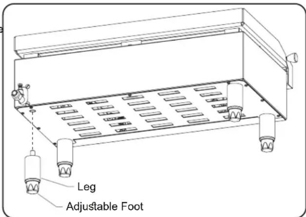
• Make sure all the feet on the bottom of the unit are positioned securely on the countertop. - Make sure the drip tray is installed on the front edge of the unit. Make sure the peg on each tray handle is seated securely in the notches on the griddle frame.
text_image
Notch Peg Drip Tray Tray HandleInstalling the Drip Tray
- Contact an authorized gas equipment installer to connect the gas supply line to the unit. Review "Connecting the Gas Supply" in this section with the installer.
Connecting the Gas Supply
Gas Griddles must be connected to an approved gas supply line by an authorized and certified gas equipment installer. Understanding the following information is required for proper and safe installation.
- Verify that the unit is configured properly for the gas supply—natural gas or propane. The specification label indicating the gas configuration of the unit is located on the back of the unit.
• Install the unit in a location with sufficient ventilation to prevent the buildup of unsafe levels of noxious fumes. - Make sure there is proper air flow around the unit for combustion air. Do not obstruct the air ventilation openings around the griddle or frame of the unit.
- Connect the unit to the gas supply piping using a moveable gas connector that complies with ANSI Z21.69 / CSA 6.16 and a quick-disconnect device that complies with ANSI Z21.41 / CSA 6.9.
- Make sure unit is installed with the included pressure regulator and gas shut-off valve.
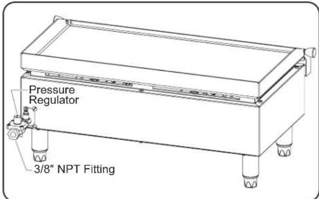
text_image
Pressure Regulator 3/8" NPT FittingRear View, Gas Connection
IMPORTANT NOTE
After shutting down a Gas Griddle, a five minute waiting period is required before relighting. This allows potential gas buildup to clear.
General
Gas Griddles are designed for ease of operation. Use the following information and procedures to operate a Gas Griddle.
WARNING
Read all safety messages in the IMPORTANT SAFETY INFORMATION section before operating this equipment.
Improper installation, operation, or maintenance of this equipment may result in property damage, serious injury, or death. Do not operate or service this equipment before reading and understanding the contents of this manual!
Control Panel
The following are descriptions of the controls used to operate a Gas Griddle. All controls are located on the control panel at the front of the unit. Each of the two cooking zones on the griddle has dedicated, identical controls.
Ignition Button
The battery powered, electronic Ignition Button ignites the two U-shaped gas burners below the griddle. Pushing the button creates a spark that ignites the burners.
Temperature Control
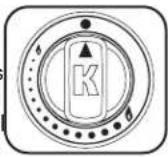
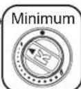
The Temperature Control controls the gas flow/temperature setting of its corresponding cooking zone. Turn the Temperature Control counterclockwise to increase the temperature setting. Turn the Temperature Control clockwise to decrease the temperature setting. The temperature settings are indicated on the control as a small flame icon followed by a series of dots increasing in size up to a large flame icon. The temperature range is up to 570°F (300°C).
NOTE: Gas griddles are equipped with a heat-activated safety thermocouple that will cut off gas supply to the unit if the burner flame(s) goes out accidentally.
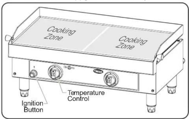
text_image
Cooking Zone Cooking Zone Ignition Button Temperature ControlOperating the Griddle
Lighting the Burners
Use the following procedure to light the burners on a Gas Griddle.
- Make sure the unit is connected properly to the gas supply and the gas shutoff valve is open. See the INSTALLATION section for details.
-
Wipe the griddle surface using a clean, damp cloth.
-
When lighting the unit for the first time after gas hook-up:
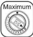
a. Push in and turn the Temperature Controls counterclockwise to their maximum setting.
b. Hold in the Temperature Controls for five seconds to flush air from the gas tubing through the burners.
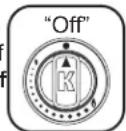
c. Release the Temperature Controls, and turn them fully clockwise to the "Off" position.
- Light the burners.
a. Push in and turn the left Temperature Control counterclockwise to its maximum setting.
b. Hold in the Temperature Control; then push the Ignition Button.
- Verify that the left burner has ignited. If not, push the Ignition Button again.
- Continue holding in the Temperature Control for ten seconds to activate the safety thermocouple, then release the Temperature Control.
c. Push in and turn the right Temperature Control counterclockwise to its maximum setting.
- Verify that the right burner has ignited. It will ignite off of the flame from the left burner.
- Continue holding in the Temperature Control for ten seconds to activate the safety thermocouple, then release the Temperature Control.
-
Allow the unit to heat for approximately five minutes. CAUTION: BURN HAZARD— Some exterior surfaces on unit will get hot. Avoid unnecessary contact with unit.
-
Turn each Temperature Control clockwise to its minimum setting. The unit is now ready for use.
NOTE: Standard and approved manufacturing oils may smoke up to 30 minutes during initial startup. This is a temporary condition. Operate unit without food product until smoke dissipates.
Operating the Unit
Startup
- Perform the "Lighting a Burner" procedure in this section, if necessary. WARNING! Never leave unit unattended during use.
CAUTION
BURN HAZARD:
- Some exterior surfaces on unit will get hot. Avoid unnecessary contact with unit.
- Do not come in contact with griddle during operation. Griddle is very hot.
Do not operate unit without installing supplied legs.
Never operate unit without drip tray installed.
- Turn each Temperature Control to the desired temperature setting, and allow the unit to preheat fully.
NOTE: Each zone on the griddle can be set to a different temperature setting. This allows the cooking of different food product at the same time.
- Apply a light coating of cooking oil onto the surface of the griddle using a heat resistant, food-safe pad or brush.
- Place food on the griddle, and cook as desired.
- Never cut food directly on the griddle surface. This will cause deep scratches on the griddle.
- Do not leave utensils sitting on the grill surface.
Shutdown
- Turn both Temperature Controls fully clockwise to the "Off" position, and close the gas shut-off valve. WARNING! Always close gas shut-off valve when unit is not in use.
IMPORTANT NOTE
After shutting down a Gas Griddle, a five minute waiting period is required before relighting. This allows potential gas buildup to clear.
- Perform the "Daily Cleaning" procedure in the Maintenance section of this manual.
General
Gas Griddles are designed for maximum durability and performance with minimum maintenance.
WARNING
Improper installation, operation, or maintenance of this equipment may result in property damage, serious injury, or death. Do not operate or service this equipment before reading and understanding the contents of this manual!
Turn Temperature Controls to OFF position, close gas shut-off valve, and allow unit to cool before performing any cleaning, adjustments, or maintenance.
FIRE OR EXPLOSION HAZARD:
- Inspect moveable gas connector regularly. Replace immediately if any signs of wear are present.
- Verify moveable gas connector has not exceeded its expiration date. Replace immediately if expired.
- Do not twist moveable gas connector.
- The unit and its individual gas shut-off valve must be disconnected and isolated from the gas supply piping system during any pressure testing of the system at test pressures in excess of 1/2 psi (3.5 kPa.).
- This unit must be isolated from the gas supply piping system by closing its individual gas shut-off valve during any pressure testing of gas supply piping system at test pressures equal to or less than 1/2 psi (3.5 kPa).
- If the information in these instructions is not followed exactly, fire or explosion may result causing property damage, personal injury, or death
- This unit must be serviced by qualified personnel only. Service by unqualified personnel may lead to explosion or burn.
- Use only Genuine Hatco Replacement Parts when service is required. Failure to use Genuine Hatco Replacement Parts will void all warranties and may subject operators of the equipment to hazardous conditions. Genuine Hatco Replacement Parts are specified to operate safely in the environments in which they are used. Some aftermarket or generic replacement parts do not have the characteristics that will allow them to operate safely in Hatco equipment.
Do not steam clean or use excessive water on unit.
This unit is not "jet-proof" construction. Do not use jet-clean spray to clean this unit.
DO NOT submerge or saturate with water. Unit is not waterproof. Do not operate if unit has been submerged or saturated with water.
This unit has no "user-serviceable" parts. If service is required on this unit, contact an Authorized Hatco Service Agent or contact the Hatco Service Department at 800-558-0607 or 414-671-6350.
CAUTION
BURN HAZARD: Allow unit to cool before performing any cleaning, adjustments, or maintenance.
NOTICE
For frame of unit, use non-abrasive cleaners and cloths only. Abrasive cleaners and cloths could scratch finish of unit, marring its appearance and making it susceptible to soil accumulation.
Do not use harsh chemicals such as bleach, cleaners containing bleach, or oven cleaners to clean this unit.
Clean unit daily to avoid malfunctions and maintain sanitary operation.
Daily Cleaning
To preserve the finish of the unit as well as maintain performance, it is recommended that the unit be cleaned daily.
-
Perform the "Shutdown" procedure in the OPERATION section of this manual.
-
Allow the unit to cool until it is slightly warm.
CAUTION
Use caution and wear protection when cleaning warm griddle. Drip tray, water, and steam will be hot.
-
Using a rigid spatula, scrape the surface of the griddle to remove all residual food and liquid, pushing it into the drip tray.
-
Carefully, empty the drip tray into an appropriate waste bin.
-
Reinstall the drip tray. Refer to the INSTALLATION section for details.
-
Put cool water or a few ice cubes onto the griddle, and allow to soak for a few minutes. This will help release cooked-on residue.
NOTE: Make sure the amount of water or ice cubes used will not overflow out of the drip tray.
-
Using a rigid spatula, push all liquid into the drip tray.
-
Using the rigid spatula to push an abrasive pad, scrub all remaining food residue from the griddle.
-
Wipe the griddle using a clean, damp cloth.
-
Apply a small amount of vinegar to the griddle to remove residual flavors and odors.
-
Empty the drip tray into an appropriate waste bin. Clean the drip tray, and reinstall onto the unit.
NOTE: Clean the griddle surface as soon as possible after cooking salty foods. Salt left on the griddle will cause corrosion.
-
Wipe the frame of the unit thoroughly using a non-abrasive cloth dampened in warm water only.
-
Dry the frame of the unit using a clean, dry, non-abrasive cloth.
NOTE: The new, stainless steel griddle surface will have a shiny appearance. Scratches will appear on the surface after time, which is normal. Eventually, these scratches will blend together to give the griddle a brushed, weathered appearance.
Converting Between Fuels
Conversion of a unit between natural gas and propane requires replacement of the orifice. This procedure must be performed by an authorized and certified gas equipment installer.
NOTE: After converting from one type of fuel to another, the spring in the pressure regulator must be changed to correspond with the gas pressure. A Spring Kit is included with the unit that contains a spring, installation instructions, and a spring identification label.
WARNING
Turn Temperature Controls to OFF position, close gas shut-off valve, and allow unit to cool before performing any cleaning, adjustments, or maintenance.
FIRE OR EXPLOSION HAZARD: This unit must be serviced by qualified personnel only. Service by unqualified personnel may lead to explosion or burn.
- If the unit already has been installed, turn both Temperature Controls fully clockwise to the "Off" position, and close the gas shut-off valve. WARNING! Always close gas shut-off valve when unit is not in use.

- Remove the drip tray.
- Remove the griddle from the frame of the unit.
a. Using a 10 mm socket wrench, loosen, but don't remove, the two hex head mounting screws that secure the griddle to the frame. One is located directly underneath each side of the griddle, near the center.
b. Carefully lift the griddle up and off of the frame, and lean it against the back of the frame. Make sure the attached thermocouple wires on each side of the griddle do not get pinched or broken.
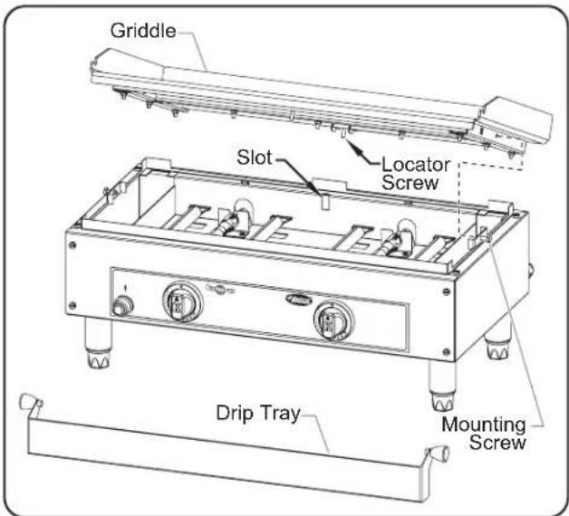
text_image
Griddle Slot Locator Screw Drip Tray Mounting ScrewRemoving the Griddle
-
On each burner, loosen but don't remove, the two burner mounting screws.
-
Slide each burner assembly toward the front of the unit to expose the installed orifices.
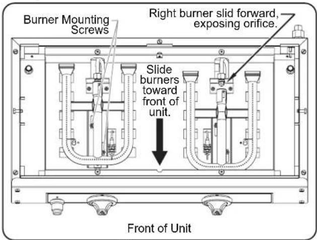
text_image
Burner Mounting Screws Right burner slid forward, exposing orifice. Slide burners toward front of unit. Front of UnitSliding the Burners
- Using a 10 mm wrench, remove both installed orifices and their corresponding washers.
• The propane orifice size is 85 μm.
• The natural gas orifice size is 120 μm.
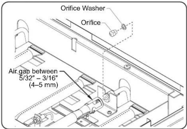
text_image
Orifice Washer Orifice Air gap between 5/32" - 3/16" (4-5 mm)Replacing an Orifice
- Install the new orifices and washers that were included in the conversion pack.
- Place the removed orifices and washers into the conversion pack for potential future use.
- Slide each burner back to its original position. Tighten the burner mounting screws securely.
- Reinstall the griddle onto the frame of the unit.
a. Align the long, locator screws underneath the middle front and rear of the griddle with the front and rear slots on the frame of the unit.
b. Lower the griddle into position onto the frame of the unit. Make sure the screw holes underneath each side of the griddle are aligned with their corresponding mounting screws on the frame.
c. Tighten the mounting screws to secure the griddle in position.
- Change the specification label to indicate the new fuel configuration.
Changing the Ignition Battery
The electronic ignition button is powered by a replaceable LR6 (1.5 V) battery. To replace the battery:
- Unscrew and remove the ignition button.
- Remove the old battery from the button housing.
- Place the new batter into the battery housing.
- Thread the ignition button onto the button housing.
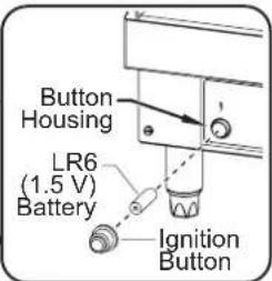
text_image
Button Housing LR6 (1.5 V) Battery Ignition ButtonSafety Thermocouple
To ensure safe operation of the gas griddle, the end of the safety thermocouple on each burner must be positioned in the flame and 5/64" (2 mm) above the burner.
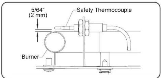
text_image
5/64" (2 mm) Safety Thermocouple BurnerIgnition Spark Plug
For proper ignition of the burners, make sure each ignition spark plug is positioned 3/16" (5 mm) from its corresponding burner.
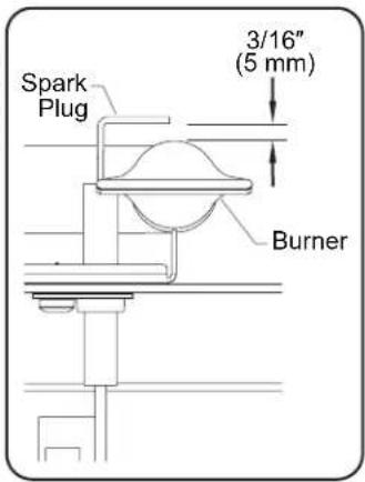
text_image
Spark Plug 3/16" (5 mm) BurnerWARNING
This unit must be serviced by qualified personnel only. Service by unqualified personnel may lead to explosion or burn.
WARNING
Turn Temperature Controls to OFF position, close gas shut-off valve, and allow unit to cool before performing any cleaning, adjustments, or maintenance.
| Symptom Probable Cause Corrective Action | ||
| Unit turned “On”, but no heat. | Safety thermostat shut down unit after flame went out. | Refer to the OPERATION section of this manual:Perform “Shutdown” procedure.Wait five minutes for gas buildup to clear.Perform “Lighting the Burners” procedure.If unit still does not heat, perform “Shutdown” procedure and contact Authorized Service Agent or Hatco for assistance. |
| Temperature Control, burner system, pressure regulator, or safety thermostat defective. | Contact Authorized Service Agent or Hatco for assistance. | |
| Unit not hot enough. | Temperature Control setting too low. | Turn Temperature Control counterclockwise to increase the temperature setting. |
| Temperature Control not calibrated properly. | Contact Authorized Service Agent or Hatco for assistance. | |
| Unit too hot. | Temperature Control setting too high. | Turn Temperature Control clockwise to decrease the temperature setting. |
| Temperature Control not calibrated properly. | Contact Authorized Service Agent or Hatco for assistance. | |
| Unit not working at all. | Unit not turned on. | Review the “Lighting the Burners” and “Operating the Unit” procedures in the OPERATION section of this manual. |
| Gas shutoff valve in closed position. | Open the gas shutoff valve, and perform the the “Lighting the Burners” and “Operating the Unit” procedures in the OPERATION section of this manual. | |
| Temperature Control, burner system, pressure regulator, or safety thermostat defective. | Contact Authorized Service Agent or Hatco for assistance. | |
Troubleshooting Questions?
If you continue to have problems resolving an issue, please contact the nearest Authorized Hatco Service Agency or Hatco for assistance. To locate the nearest Service Agency, log onto the Hatco website at www.hatcocorp.com, select the Support pull-down menu, and click on "Find A Service Agent"; or contact the Hatco Parts and Service Team at:
Telephone: 800-558-0607 or 414-671-6350
e-mail: support@hatcocorp.com
1. PRODUCT WARRANTY
Hatco warrants the products that it manufactures (the "Products") to be free from defects in materials and workmanship, under normal use and service, for a period of one (1) year from the date of purchase when installed and maintained in accordance with Hatco's written instructions or 18 months from the date of shipment from Hatco. Buyer must establish the Product's purchase date by registering the Product with Hatco or by other means satisfactory to Hatco in its sole discretion.
Hatco warrants the following Product components to be free from defects in materials and workmanship from the date of purchase (subject to the foregoing conditions) for the period(s) of time and on the conditions listed below:
a) One (1) Year Parts and Labor PLUS One (1) Additional Year Parts-Only Warranty:
Conveyor Toaster Elements (metal sheathed)
Drawer Warmer Elements (metal sheathed)
Drawer Warmer Drawer Rollers and Slides
Strip Heater Elements (metal sheathed)
Display Warmer Elements (metal sheathed air heating)
Holding Cabinet Elements (metal sheathed air heating)
Heated Well Elements — HW and HWB Series
(metal sheathed)
b) Two (2) Year Parts and Labor Warranty:
Induction Ranges
Induction Warmers
c) One (1) Year Parts and Labor PLUS Four (4) Years
Parts-Only Warranty:
3CS and FR Tanks
d) One (1) Year Parts and Labor PLUS Nine (9) Years Parts-Only Warranty on:
Electric Booster Heater Tanks
Gas Booster Heater Tanks
e) Ninety (90) Day Parts-Only Warranty:
Replacement Parts
THE FOREGOING WARRANTIES ARE EXCLUSIVE AND IN LIEU OF ANY OTHER WARRANTY, EXPRESSED OR IMPLIED, INCLUDING BUT NOT LIMITED TO ANY IMPLIED WARRANTY OF MERCHANTABILITY OR FITNESS FOR A PARTICULAR PURPOSE OR PATENT OR OTHER INTELLECTUAL PROPERTY RIGHT INFRINGEMENT. Without limiting the generality of the foregoing, SUCH WARRANTIES DO NOT COVER: Coated incandescent light bulbs, fluorescent lights, heat lamp bulbs, coated halogen light bulbs, halogen heat lamp bulbs, xenon light bulbs, LED light tubes, glass components, and fuses; Product failure in booster tank, fin tube heat exchanger, or other water heating equipment caused by liming, sediment buildup, chemical attack, or freezing; or Product misuse, tampering or misapplication, improper installation, or application of improper voltage.
2. LIMITATION OF REMEDIES AND DAMAGES
Hatco's liability and Buyer's exclusive remedy hereunder will be limited solely, at Hatco's option, to repair or replacement using new or refurbished parts or Product by Hatco or a Hatco-authorized service agency (other than where Buyer is located outside of the United States, Canada, United Kingdom, or Australia, in which case Hatco's liability and Buyer's exclusive remedy hereunder will be limited solely to replacement of part under warranty) with respect to any claim made within the applicable warranty period referred to above. Hatco reserves the right to accept or reject any such claim in whole or in part. In the context of this Limited Warranty, "refurbished" means a part or Product that has been returned to its original specifications by Hatco or a Hatco-authorized service agency. Hatco will not accept the return of any Product without prior written approval from Hatco, and all such approved returns shall be made at Buyer's sole expense. HATCO WILL NOT BE LIABLE, UNDER ANY CIRCUMSTANCES, FOR CONSEQUENTIAL OR INCIDENTAL DAMAGES, INCLUDING BUT NOT LIMITED TO LABOR COSTS OR LOST PROFITS RESULTING FROM THE USE OF OR INABILITY TO USE THE PRODUCTS OR FROM THE PRODUCTS BEING INCORPORATED IN OR BECOMING A COMPONENT OF ANY OTHER PRODUCT OR GOODS.
Introduction......15
1. GARANTIE DU PRODUIT
Industrial Electric Commercial Parts & Service, Inc. Huntington Beach 714-379-7100
Chapman Appl. Service San Diego 619-298-7106
P & D Appliance Commercial Parts & Service, Inc.
S. San Francisco 650-635-1900
COLORADO
Hawkins Commercial Appliance Englewood 303-781-5548
FLORIDA
Whaley Foodservice Repair Jacksonville 904-725-7800 Whaley Foodservice Repair Orlando 407-757-0851
B.G.S.I./Heritage Pompano Beach 954-971-0456
Comm. Appliance Service Tampa 813-663-0313
GEORGIA
Heritage Service Group Norcross 866-388-9837
HAWAII
Burney's Comm. Service, Inc. Honolulu 808-848-1466 Food Equip Parts & Service Honolulu 808-847-4871
ILLINOIS
Parts Town Addison 708-865-7278
Eichenauer Elec. Service Decatur 217-429-4229
Midwest Elec. Appl. Service Elmhurst 630-279-8000 Cone's Repair Service Moline 309-797-5323
IOWA
Goodwin Tucker Group
Des Moines 515-262-9308
KENTUCKY
Tech 24 Lexington 859-254-8854
Tech 24 Louisville 502-451-5411
LOUISIANA
Chandlers Parts & Service Baton Rouge 225-272-6620
MARYLAND
Electric Motor Service Baltimore 410-467-8080
MASSACHUSETTS
Ace Service Co., Inc. Needham 781-449-4220
MICHIGAN
Bildons Appliance Service Detroit 248-478-3320
Commercial Kitchen Service Bay City 989-893-4561
Midwest Food Equip. Service Grandville 616-261-2000
MISSOURI
General Parts Kansas City 816-421-5400
Commercial Kitchen Services St. Louis 314-890-0700
Kaemmerlen Parts & Service St. Louis 314-535-2222
NEBRASKA
Anderson Electric Omaha 402-341-1414
NEVADA
Burney's Commercial Las Vegas 702-736-0006
Hi. Tech Commercial Service N. Las Vegas 702-649-4616
NEW JERSEY
Jay Hill Repair Fairfield 973-575-9145 Service Plus Flanders 973-691-6300
NEW YORK
Alpro Service Co. Maspeth 718-386-2515 Duffy's - AIS Buffalo 716-884-7425 3Wire Plattsburgh 800-634-5005 Duffy's - AIS Sauquoit 800-836-1014 J.B. Brady, Inc. Syracuse 315-422-9271
NORTH CAROLINA
Authorized Appliance Charlotte 704-377-4501
OHIO
Akron/Canton Comm. Svc. Inc. Akron 330-753-6634 Tech 24 Cincinnati 513-772-6600
Commercial Parts and Service Columbus 614-221-0057
Electrical Appl. Repair Service Brooklyn Heights 216-459-8700
E. A. Wichman Co. Toledo 419-385-9121
OKLAHOMA
Hagar Rest. Service, Inc. Oklahoma City 405-235-2184
OREGON
General Parts Group Portland 503-624-0890
PENNSYLVANIA
Elmer Schultz Services Philadelphia 215-627-5401
FAST Comm. Appl. Service Philadelphia 215-288-4800
AIS Commercial Parts and Service Pittsburgh 412-809-0244
K & D Service Co. Harrisburg 717-236-9039
Electric Repair Co. Reading 610-376-5444
RHODE ISLAND
Marshall Electric Co. Providence 401-331-1163
SOUTH CAROLINA
Whaley Foodservice Repair Lexington 803-996-9900
TENNESSEE
Camp Electric Memphis 901-527-7543
TEXAS
Armstrong Repair Service Houston 713-666-7100
Cooking Equipment Specialist Mesquite 972-686-6666
Commercial Kitchen Repair Co. San Antonio 210-735-2811
UTAH
La Monica's Rest. Equip. Service Murray 801-263-3221
VIRGINIA
Daubers Norfolk 757-855-4097 Daubers Springfield 703-866-3600
WASHINGTON
3Wire Seattle 800-207-3146
WISCONSIN
A.S.C., Inc. Madison 608-246-3160 A.S.C., Inc. Milwaukee 414-543-6460
CANADA
ALBERTA
Key Food Equipment Service Edmonton 780-438-1690
BRITISH COLUMBIA
Key Food Equipment Service Vancouver 604-433-4484 Key Food Equipment Service Victoria 250-920-4888
MANITOBA
Air Rite, Inc. Winnipeg 204-895-2300
NEW BRUNSWICK
EMR Services, Ltd. Moncton 506-855-4228
ONTARIO
R.G. Henderson Ltd. Toronto 416-422-5580 Choquette - CKS, Inc. Ottawa 613-739-8458
QUÉBEC
Choquette - CKS, Inc. Montreal 514-722-2000
Choquette - CKS, Inc. Québec City 418-681-3944
UNITED KINGDOM
Marren Group Northants +44(0)1933 665313
HATCO CORPORATION
P.O. Box 340500
Milwaukee, WI 53234-0500 U.S.A.
800-558-0607 414-671-6350
support@hatcocorp.com
www.hatcocorp.com
Register your unit online!
See IMPORTANT OWNER INFORMATION section for details.