
11-264 - Pressure measuring tool NEO tools - Free user manual and instructions
Find the device manual for free 11-264 NEO tools in PDF.

| Product type | Fuel injection pressure test kit |
| Brand | NEO tools |
| Model | 11-264 |
| Intended use | Fuel pressure measurement in gasoline injection systems (PFI and TBI) |
| Measurement range | 0-140 psi / 0-10 bar |
| Gauge diameter | 92 mm (3 1/2") |
| Kit contents | Pressure gauge with flexible adapter, 30 adapters and fittings, hoses, clamps, carrying case |
| Fuel type | Gasoline only (no Diesel) |
| Power supply | None (used with vehicle's system) |
| Weight (estimated) | 2.5 kg |
| Case dimensions (estimated) | 45 x 30 x 10 cm |
| Material | Steel, rubber, plastic, brass |
| Safety valve | Yes, with drain hose for fuel recovery |
| Safety precautions | Do not use on hot engine, avoid sparks, wear safety glasses, work in a ventilated area |
| Maintenance | Clean after use, drain the gauge, store in the case |
| Cleaning | Wipe up spilled fuel, use a clean cloth |
| Storage | In a dry place, out of reach of children |
| Spare parts | Adapters and seals available (references VSE2 12.V2-01 to VSE212.V2-31) |
| Repairability | Possible by replacing parts, requires mechanical knowledge |
| Warranty | Not specified, refer to retailer |
Frequently Asked Questions - 11-264 NEO tools
User questions about 11-264 NEO tools
0 question about this device. Answer the ones you know or ask your own.
Ask a new question about this device
Download the instructions for your Pressure measuring tool in PDF format for free! Find your manual 11-264 - NEO tools and take your electronic device back in hand. On this page are published all the documents necessary for the use of your device. 11-264 by NEO tools.
USER MANUAL 11-264 NEO tools
natural_image
Open industrial tool kit with various pressure gauges and tubing (no visible text or labels)PL UNIWERSALNY ZESTAW DO POMIARU CIŚNIENIA WTRYSKU PALIWA
EN MASTER FUEL INJECTOR PRESSURE TEST KIT
DE UNIVERSAL-SET ZUR EINSPRITZDRUCKMESSUNG

INSTRUKCJA OBSŁUGI UNIWERSALNY ZESTAW DO POMIARU CIŚNIENIA WTRYSKU PALIWA
11-264
WAŻNE: NALEŻY UWAŻNIE PRZECZYTAĆ TĘ INSTRUKCJĘ OBSŁUGI. NALEŻY PAMIĘTAĆ O WYMAGANIACH BEZPIECZNEJ PRACY, OSTRZEŻENIACH I PRZESTROGACH. PRODUKTU UŻYWAĆ PRAWIDŁOWO I ZGODNIE Z PRZEZNACZENIEM. ZANIEDBANIE TEGO ZALECENIA UNIEWAŻNI GWARANCJĘ I MOŻE SPOWODOWAĆ USZKODZENIA I/LUB OBRAŻENIA OSOBISTE.
1. INSTRUKCJE BEZPIECZEŃSTWA
IMPORTANT: PLEASE READ THESE INSTRUCTIONS CAREFULLY. NOTE THE SAFE OPERATIONAL REQUIREMENTS, WARNINGS, AND CAUTIONS. USE THIS PRODUCT CORRECTLY, AND WITH CARE FOR THE PURPOSE FOR WHICH IT IS INTENDED. FAILURE TO DO SO MAY CAUSE DAMAGE AND/OR PERSONAL INJURY AND WILL INVALIDATE THE WARRANTY.
1. SAFETY INSTRUCTIONS
1.1. Fuel safety
- Warning! Ensure health and safety, local authority, and general workshop practice regulations are adhered to when working with fuel injection systems and petrol in general.
- Warning! Petrol fumes and battery gases are explosive, do not smoke or allow a naked flame or sparks in the work area.
1.1.1 fuel leaks
- Keep a dry chemical (class b) fire extinguisher near to the work area.
- Avoid fire hazard by using caution when disconnecting fuel lines and installing adaptors, as some spillage is inevitable.
- When connecting, or disconnecting from a fuel system, relieve pressure from system and wrap a cloth around the fuel line fitting to absorb any fuel leakage. Constantly check gauge and adaptor connections for leaks. If you see leakage turn off the ignition or disable the fuel pump, relieve fuel pressure if necessary and correct leaks before continuing.
- When using 'tee' adaptors, secure hose with hose clamps to ensure leak-free connections.
- Check all adaptor sealing washers and ,o' rings are in good condition before use.
- When connecting hose coupler to test port, tee and in-line banjo bolt adaptors ensure coupler is correctly seated onto adaptor.
- do not let fuel spill onto a hot engine.
- do not allow fuel to remain in the adaptors or hoses after use. To clear any fuel trapped in the gauge/hose assembly after use, hold gauge vertical with hose coupler end in suitable fuel container. Depress coupler valve stem and at the same time, depress pressure relief button situated under the gauge.
- Warning! Wipe up fuel spills immediately.
1.2. General
- Warning! Exhaust gas contains deadly poisonous gases. Test area must be well ventilated - route exhaust gas outdoors.
- Maintain tools in good and clean condition for best and safest performance.
- If required, ensure the vehicle to be worked on is adequately supported with axle stands, ramps and chocks.
- Before performing a test with the engine running (unless the manufacturer's manual states otherwise), set the parking brake and place the gear selector in neutral or park, and block the drive wheels.
- Before repairing the fuel system, turn off the ignition switch and disconnect the battery per manufacturer's procedure. Never disconnect the battery while the engine is running.
- Wear approved safety goggles.
- Wear suitable clothing to avoid snagging. Do not wear jewellery and tie back long hair.
- Keep yourself, clothing and test equipment away from all moving or hot engine parts.
- Keep children and unauthorised persons away from working area.
- do not use components from this kit if damaged.
- do not use the equipment for purposes other than for which it is designed.
- do not use the components from this kit on diesel fuel systems.
- do not use the equipment when you are tired or under the influence of alcohol, drugs or intoxicating medicines.
- Account for all tools being used and do not leave them in or near the engine.
- When not in use clean kit components, replace in case and store in a dry, safe, childproof area,
- Important: always refer to the vehicle manufacturer's service instructions, or proprietary manual to establish the current procedure and data. These instructions are provided as a guide only.
- Warning! It is assumed that anybody using the vse212.v2 will have some knowledge of the mechanics of the vehicle, particularly in regard to safe handling of fuel systems. If there is any doubt refer the job to a professional mechanic.
2. INTRODUCTION
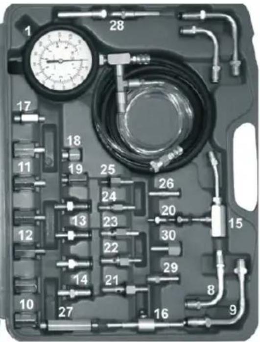
Comprehensive kit of hoses, adaptors and fittings for testing the pressure on modern petrol fuel injection systems. Fitted with quick couplings and safety valve to prevent inadvertent discharge of fuel under pressure. Supplied with 92mm single high pressure gauge with rubber bumper, reading 0-140psi and 0-10bar. Pressure release valve fitted with long drain hose allows safe recovery of fuel. Supplied in carry-case.
- TOOL PARTS & CONTENT LIST
| ITEM | PART NO. | DESCRIPTION |
| 1 | VSE212.V2-01 | Gauge 3-1/2" with hose adaptor assembly 140psi |
| 2 | VSE212.V2-02 | Connecting hose & valve assembly for bosch cis |
| 3 | VSE212.V2-03 | Connecting hose for gm tbi |
| 4 | VSE212.V2-04 | Adaptor ford efi |
| 5 | VSE212.V2-05 | Adaptor ford efi |
| 6 | VSE212.V2-06 | Quick connect to adaptor small schrader for ford applications |
| 7 | VSE212.V2-07 | Quick connect to adaptor standard schrader. |
| 8 | VSE212.V2-08 | 2X adaptor ø10mm tubing with male 5/8" - 18unf fittings. |
| 9 VSE212.V2-09 2X adaptor ø10mm tubing with male 5/8"-18 to m16x1.5 With 'o' ring fittings. | |
| 10 VSE212.V2-10 2X adaptor female m16x1.5 To female 5/8"-18unf. | |
| 11 VSE212.V2-11 2X adaptor female m14x1.5 To ø3/8" tube fitting. | |
| 12 VSE212.V2-12 2X adaptor female m16x1.5 To ø3/8" tube fitting. | |
| 13 VSE212.V2-13 2X adaptor male m14x1.5 With 'o' ring to ø3/8" tube fitting | |
| 14 VSE212.V2-14 2X adaptor male m16x1.5 With 'o' ring to ø10mm tube fitting | |
| 15 VSE212.V2-15 Adaptor for izuzu i-tec systems. | |
| 16 VSE212.V2-16 Quick connect manifold with ø1/14"- 5/16" tube fittings | |
| 17 VSE212.V2-17 Adaptor male m12x1.5 To male m10x1.0With 'o' ring for mercedes benz applications | |
| 18 VSE212.V2-18 Adaptor male m12x1.5 To female m10x1.0 For ford/volkswagen 16v applications | |
| 19 VSE212.V2-19 Adaptor male m12x1.5 To female m8x1.0 For bmw applications | |
| 20 VSE212.V2-20 2X adaptor male m12x1.5 To male m8x1.0 With 'o' ring for mercedes benz, vw golf & bmw applications | |
| 21 VSE212.V2-21 Adaptor quick connect to m12x1.25 Banjo fitting with nylotron | |
| 22 VSE212.V2-22 Adaptor quick connect to m12x1.5 Banjo fitting with brass washers | |
| 23 VSE212.V2-23 Adapter quick connect to m10x1.0 Banjo fittings for triumph applications | |
| 24 VSE212.V2-24 Adapter quick connect to m8x1.0 Banjo fitting with brass washers for toyota applications. | |
| 25 VSE212.V2-25 Adaptor quick connect to male m6x1.0 With 'o' ring for suzuki applications | |
| 26 VSE212.V2-26 Adaptor quick connect to1/4" tubing barb for bosch mono jetronic applications | |
| 27 VSE212.V2-27 Adaptor male m12x1.5 To male m8x1.0 With 'o' ring for audi secondary adaptor applications. | |
| 28 VSE212.V2-28 2X m14x1.5 Male adaptor. | |
| 29 VSE212.V2-29 M14x1.5 Male adaptor. | |
| 30 VSE212.V2-30 M14x1.5 Female adaptor | |
| 31 VSE212.V2-31 Case | |
4. GENERAL INFORMATION
Because fuel systems and access points are so varied, it is impractical to list all of the applications. Always refer to a reliable workshop manual, or the car manufacturer for the recommended test procedure and access points before commencing any work on fuel injection systems.
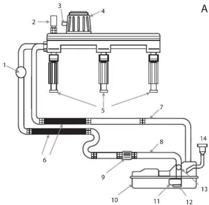
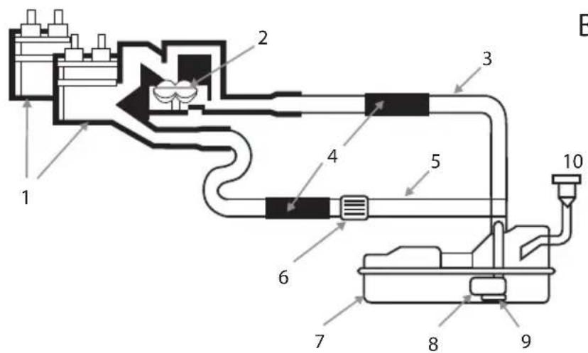
There are two basic types of fuel injection systems. Port fuel injection (pfi) (fig.A) uses separate injectors to supply the fuel to each cylinder. Throttle body injection (tbi) (fig.B) injects fuel from a position above the throttle plate on the intake manifold. On both systems there is a supply side, which brings fuel to the injectors, and a return side which brings unused fuel back to the tank.
5. BASIC PORT FUEL INJECTION (PFI) SYSTEM
Fig. A
| 1 Pulse Dampener |
| 2 Test Port (schrader Valve) |
| 3 Manifold Vacuum Hose Connection |
| 4 Pressure Regulator |
| 5 Fuel Injectors |
| 6 Flexible Hose |
| 7 Fuel Return Line |
| 8 Fuel Pressure Line |
| 9 In-line Fuel Filter |
| 10 Fuel Tank |
| 11 In-tank Fuel Pump |
| 12 Pump Inlet Filter |
| 13 Pulsator |
| 14 Fuel Cap |
6. BASIC THROTTLE BODY INJECTION (TBI) SYSTEM.
Fig.B
| 1 tbi unit fuel injectors |
| 2 throttle body pressure regulator |
| 3 fuel return line |
| 4 flexible hose |
| 5 fuel pressure line |
| 6 in-line fuel filter |
| 7 fuel tank |
| 8 in-tank fuel pump |
| 9 pump inlet filter |
| 10 fuel cap |
7. BASIC DIAGNOSTIC CHECKS
Before testing the fuel injection system it is recommended to carry out the following basic checks:
7.1 FUEL SYSTEM
7.1.1. Ensure that there is sufficient fuel in the fuel tank. Do not rely on the vehicle's fuel gauge, make a physical check.
7.1.2. Check for damaged, broken or loose metal and flexible fuel lines. Look for evidence of fuel leaks.
7.1.3. Ensure that there is no water or any other contaminants in the fuel.
7.1.4. Check the fuel tank venting system and the condition of the fuel filler cap.
7.1.5. Check any fuel system related electrical fuses.
7.2 Electrical system
7.2.1. Look for any disconnected electrical components.
7.2.2. Check the vehicle ignition system and ensure that the spark plugs are functioning correctly.
7.2.3. Observe for any fault lamps illuminated on the vehicle dashboard. If necessary use an eobd code reader (available from your sealey dealer) to retrieve any fault codes from the vehicle.
7.2.4. Check the condition of the battery as the electrical components on the fuel injection system will rely on the battery to function.
7.3 Vacuum system
7.3.1. Check the vacuum system for any loose or disconnected pipes.
7.3.2. With the engine running, listen for any air leaks or unusual noises.
7.3.3. Look for any oil leaks in or around the vacuum system.
7.3.4. Check the inlet manifold for cracks or leaking gaskets.
8. BASIC FUEL INJECTION PRESSURE TESTING.
Fuel injected engines require precise fuel pressure as well as adequate volume. Without the correct pressure and volume, performance and fuel economy can suffer. Always consult the correct workshop manual or vehicle manufacturer for accurate specifications and testing procedures.
When running tests, it may help to picture the fuel system as a circle. Fuel is pumped from the tank to the fuel regulator and injectors, and the unused fuel is then returned to the tank. The fuel regulator serves as a divider between the supply side and the return side.
The adaptors supplied with this kit are suitable for use on most fuel injection systems fitted to american, european and asian vehicles. There are three ways to check fuel pressure. First, many vehicles with pfi are equipped with a special test port. Simply connect the proper adaptor to the gauge assembly, thread the adaptor to the test port, and run the test. Second is an end of hose connection. Some older pfi systems have a flexible hose connection at the cold start injector. Connect the single barb fitting with a hose clamp to run the test. Also, some systems have fuel bolts or banjo type fittings as an access point. Third is in-line connecting. This means installing the proper adaptor(s) in series with the fuel line.
Unless a schrader-type test port is available, most manufacturers require that you relieve the fuel pressure before entering or leaving the system. To relieve the pressure, it may be necessary to remove the fuel pump connector, relay, or fuse. Some models may have two fuel pumps - make sure both are disabled. After the pump(s) is/are disabled, run the engine until it stalls, then try to restart it for five to ten seconds. The system is now ready for testing.
8.1 BASIC TESTING PROCEDURE
Note: the following is intended as a guide only, always refer to the vehicle manufacturer or a workshop manual for specific fuel injection system pressure testing. Caution: high fuel pressure may be present in fuel lines and component parts. Relieve pressure before attempting to open system for testing or component replacement. Do not allow fuel to run onto engine or electrical parts while testing fuel system components.
8.1.1. Ensure that the ignition and engine is switched off before the test.
8.1.2. Connect the gauge assembly to the high pressure side of fuel injection system by one of the methods as described above using the correct adaptor. Where necessary, ensure that the pressure has been relieved from the fuel system.
8.1.3. Carry out the test procedures as stated by the manufacturer or workshop manual. Note: any testing that requires the engine to be running should only be done at tickover.
8.1.4. Observe reading on gauge assembly and compare to vehicle manufacturer's specifications.
A higher than normal pressure usually indicates a problem on the return side of the circle and a lower than recommended pressure usually indicates a problem on the supply side of the circle.
8.2 Possible causes of higher than recommended fuel pressure.
8.2.1. Defective fuel pressure regulator.
8.2.2. Restriction in fuel return line.
8.2.3. Defective safety valve or fuel pump at tank.
8.2.4. Excessive tank pressure caused by improper venting.
8.3 Possible causes of lower than recommended fuel pressure.
8.3.1. Blocked fuel filter.
8.3.2. Restriction in fuel supply line.
8.3.3. Defective fuel pump
8.3.4. Defective pressure regulator
8.3.5. Blocked pump inlet filter
8.3.6. Vacuum in tank caused by improper venting.
You may be able to pinpoint problem areas on the return side by retesting. For example - by removing the return line near the fuel regulator and putting the fuel line into a proper container, a retest that still shows a high reading would indicate a faulty regulator. If the reading would drop into the normal range, you know that problem is further down the return line or the tank. Again, always consult the manufacturer of the vehicle, or a good workshop manual for specific trouble-shooting procedures. When testing is completed, make sure the fuel line is reassembled correctly. Replace any o-rings or washers, and follow the manufacturer's recommendations for proper torque on any bolts or connections. Check the entire system thoroughly for any leaks.
9. PRESSURE UNIT OF MEASUREMENT CONVERSION CHART.
| PSI Bar K/Pa KG/cm2 | ||
| 0,5 0,034 3 44 0,352 | ||
| 1,0 0,069 6 89 0,0703 | ||
| 1,25 0,086 8,62 0,0879 | ||
| 2,0 0,138 13,79 0,1406 | ||
| 5,0 0,345 34,48 0,3515 | ||
| 10,0 0,699 69,85 0,7030 | ||
| 15,0 1,034 103,43 1,0545 | ||
| 20,0 1,379 137,90 1,4060 | ||
| 25,0 1,724 172,38 1,75 | ||
| 30,0 2,069 206,85 2,1090 | ||
| 35,0 2,143 241,33 2,4605 | ||
| 40,0 2,758 275,80 2,8120 | ||
| 50,0 3,448 344,75 3,5150 | ||
| 60,0 4,137 413,70 4,2180 | ||
| 70,0 4,827 482,65 4,9210 | ||
| 80,0 5,516 551,60 5,6240 | ||
| 90,0 6,206 620,55 6,3270 | ||
| 100,0 6,895 689,50 7,0300 |
ENVIRONMENTAL PROTECTION.
Recycle unwanted materials instead of disposing of them as waste. all tools, accessories and packaging should be sorted, taken to a recycle centre and disposed of in a manner which is compatible with the environment.

BEDIENUNGSANLEITUNG
UNIVERSAL-SET ZUR
EINSPRITZDRUCKMESSUNG
11-264

- INSTRUKCJA OBSŁUGI UNIWERSALNY ZESTAW DO POMIARU CIŚNIENIA WTRYSKU PALIWA
- INSTRUKCJE BEZPIECZEŃSTWA
- SAFETY INSTRUCTIONS
- Fuel safety
- fuel leaks
- General
- INTRODUCTION
- GENERAL INFORMATION
- BASIC PORT FUEL INJECTION (PFI) SYSTEM
- BASIC THROTTLE BODY INJECTION (TBI) SYSTEM.
- BASIC DIAGNOSTIC CHECKS
- FUEL SYSTEM
- Electrical system
- Vacuum system
- BASIC FUEL INJECTION PRESSURE TESTING.
- BASIC TESTING PROCEDURE
- Possible causes of higher than recommended fuel pressure.
- Possible causes of lower than recommended fuel pressure.
- PRESSURE UNIT OF MEASUREMENT CONVERSION CHART.
- ENVIRONMENTAL PROTECTION.
- BEDIENUNGSANLEITUNG
- UNIVERSAL-SET ZUR
- EINSPRITZDRUCKMESSUNG
Brand : NEO tools
Model : 11-264
Category : Pressure measuring tool