
X1 - Electric winch Lofrans - Free user manual and instructions
Find the device manual for free X1 Lofrans in PDF.


| Product type | Electric winch |
| Brand | Lofrans |
| Model | X1 |
| Motor power | 500 W / 800 W / 1000 W |
| Supply voltage | 12 V |
| Recommended boat length (heavy duty) | 20-30 ft (500 W), 25-35 ft (800 W), 30-40 ft (1000 W) |
| Recommended boat length (light duty) | 30-35 ft (500 W), 35-40 ft (800 W), 35-45 ft (1000 W) |
| Maximum line pull | 630 kg (500 W), 700 kg (800 W), 900 kg (1000 W) |
| Maximum lift load | 345 kg (500 W), 380 kg (800 W), 425 kg (1000 W) |
| Maximum working load | 95 kg (500 W), 100 kg (800 W), 125 kg (1000 W) |
| Current under load | 60 A (500 W), 110 A (800 W), 120 A (1000 W) |
| Maximum line speed | 26 m/min (500 W), 28 m/min (800 W), 30 m/min (1000 W) |
| Net weight with drum | 12 kg (500 W), 14 kg (800 W), 17 kg (1000 W) |
| Net weight low profile | 11 kg (500 W), 13 kg (800 W), 16 kg (1000 W) |
| Supported chains | 6 mm, 7 mm, 8 mm (DIN 766, ISO, BBB, G4) |
| Supported rope | 12 mm - 1/2" |
| Protection rating | IP67 (500 W / 800 W models) |
| Warranty | 3 years |
| Material | Stainless steel or aluminium (X1 Alu) |
| Use | Pleasure boating |
| Maintenance | Periodic program (cleaning, lubrication, checking connections, replacing seals) |
| Safety | Magnetic thermal circuit breaker, safety switch, manual clutch |
Frequently Asked Questions - X1 Lofrans
User questions about X1 Lofrans
0 question about this device. Answer the ones you know or ask your own.
Ask a new question about this device
Download the instructions for your Electric winch in PDF format for free! Find your manual X1 - Lofrans and take your electronic device back in hand. On this page are published all the documents necessary for the use of your device. X1 by Lofrans.
USER MANUAL X1 Lofrans
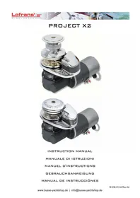
Verricelli Verticali
Vertical Windlasses
CONSERVARE QUESTO MANUALE A BORDO STORE THIS MANUAL ON BOARD CONSERVER CE MANUEL A BORD DIESES HANDBUCH AN BORD AUEBEWAHREN GUARDAR ESTE MANUAL A BORDO
MANUALE DI INSTALLAZIONE E D'USO - INSTALLATION AND USER'S MANUAL MANUEL D'INSTALLATION ED D'UTILISATION - MANUAL DE INSTALACIÓN Y USO INSTALLATION UND BEDIENUNG
X1 - X1 ALU - X1 Dark Version
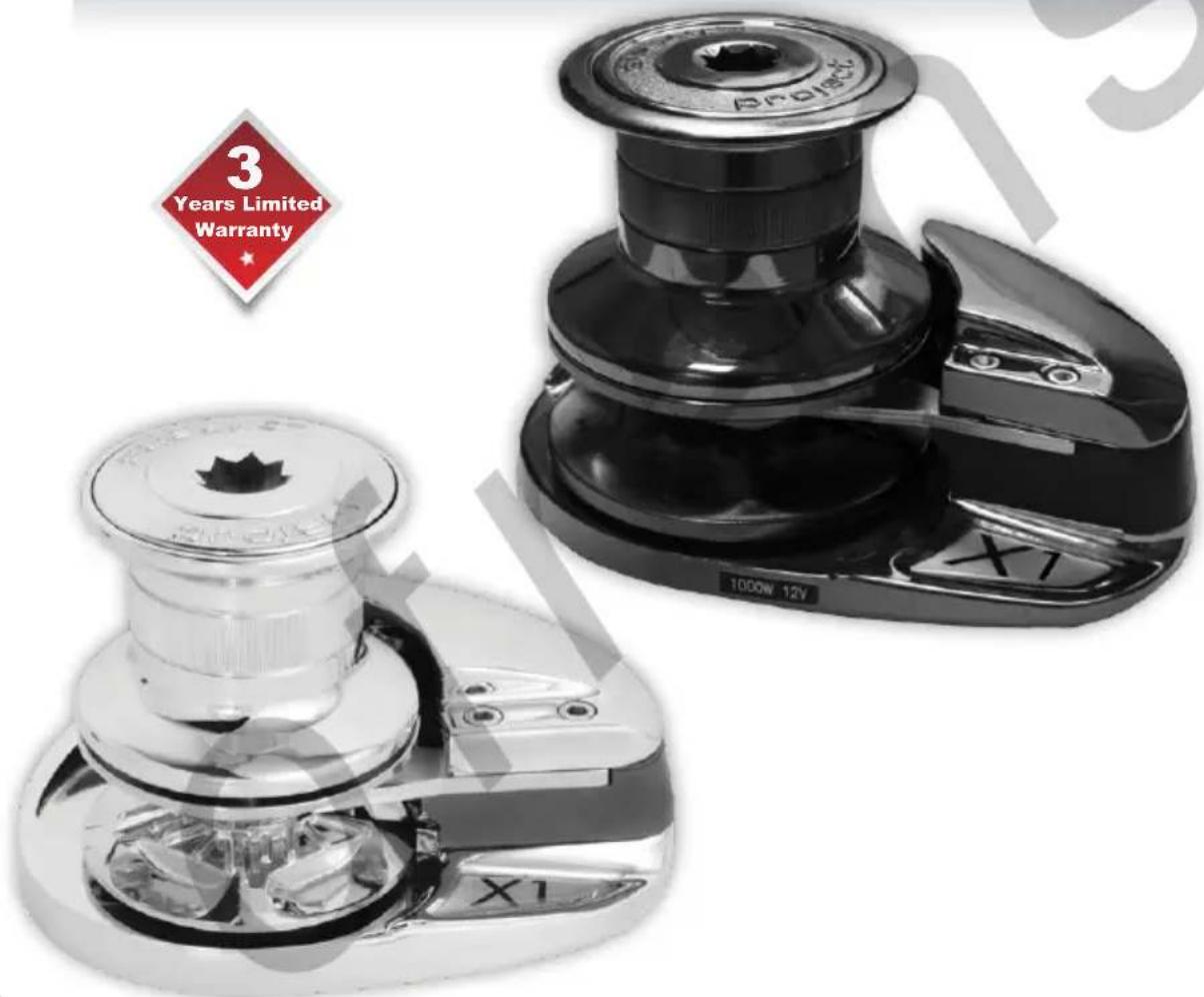
UK
IT
FR
DE
ES
Lofrans ^1 ®
WINDLASSES
THE ORIGINAL WINDLASS
Dear Customer,
Thank you for choosing a Lofrans" product. Lofrans" is a leader company in the production and worldwide distribution of nautical systems manufactured according to the most modern technologies, in compliance with international regulation requirements and the most important certifying bodies. All our products are manufactured with excellent materials suited for operations in marine environments and are subject to continuous checks to improve the qualitative levels and make them without any manufacturing defects. Together with such requirements, Lofrans' anchor windlasses are a synthesis of reliability and efficiency, by guaranteeing the maximum performances during each phase of mooring, even in the most difficult. With a Lofrans' product, years of reliable operations are guaranteed.
Lofrans© copyright, 2024. All rights reserved.
Lofrans' declines any liability for possible inaccuracies due to print errors in this manual and reserves the right to introduce any changes deemed appropriate. For this reason, Lofrans' does not guarantee the accuracy of the manual after the date of issue and declines all liability for possible errors and omissions.
TABLE OF CONTENTS
1 INTRODUCTION 3
1.1 Purpose of the manual 3
1.2 Assistance 3
1.3 Receipt and storage 3
2 SAFETY INFORMATION 3
3 INSTALLATION 4
3.1 Contents of the package 4
3.2 Equipment necessary for installation 4
3.3 Recommended accessories 4
3.4 General requirements for installation 4
3.5 Prevention from electrolysis 5
3.6 Deck thickness 5
3.7 Deck installation 5
3.8 Under deck installation 5
3.9 Chain insertion 6
4.1 Electrical cable section 6
4.2 Solenoid valves (Control Box)____6
4.3 Circuit breakers 6
4.4 Remote control electric panel board 6
4.5 Wiring diagram 7
5 USE OF THE WINDLASS 8
5.1 Lowering the anchor 8
5.1.1 Lowering the anchor electrically 8
5.1.2 Lowering the anchor by gravity 9
5.2 Weighing the anchor 9
5.3 of the warping drum 10
5.4 Notes for use 10
6 MAINTENANCE 10
6.1 Maintenance programme 11
6.2 Gipsy maintenance/replacement 11
7 TROUBLESHOOTING 11
8 TECHNICAL DATA 13
9 SPARE PARTS 14
10 OVERALL DIMENSIONS 18
11 DRILLING TEMPLATE 19
12 WARRANTY CONDITIONS 20
12.1 Conditions and limits 20
12.2 Exceptions 20
12.3 Liability 20
12.4 Procedure 20
12.5 Clause of Termination 20
12.6 Compliance 20
PRODUCT COMPLIANT WITH EC REGULATIONS
1 INTRODUCTION
1.1 Purpose of the manual
This manual will supply information on safety and correct use of the product. Follow these warnings carefully to avoid possible accidents or damages.

DANGER!
A warning such as this indicates the existence of a serious risk that has high probabilities to cause death or a serious accident if appropriate precautions are not taken.

ATTENTION!
A warning such as this indicates a reference to the application of safety practices, or draws the attention on unsafe behaviours that might cause personal injuries or damages to the boat.
1.2 Assistance
The Lofrans' products are backed throughout the world by a network of authorised distributors and assistance. In case of need, please contact your local Lofrans' s.r.l distributor. Details on website www.Lofrans'.com.

1.3 Receipt and Storage
Upon receipt of the package, verify the integrity of packing. Should it be necessary to store the product for a prolonged period, keep it in a dry and protected place.
2 SAFETY INFORMATION
Safety standards and certifying bodies require peremptorily that, during the standing of the anchor, the load must be held by a chain stopper or a high resistance fixing point. The user is responsible for guaranteeing that during navigation the anchor is properly stowed and fixed. This precaution is more important when the navigation speed is higher and sea conditions are worse. Indeed, an anchor paid out by mistake during navigation can have very serious effects. Considering its position and not always frequent use, the anchor windlass is particularly exposed to oxidation and corrosion risk; therefore, it is necessary to arrange a constant inspection of its parts and a due maintenance. Make sure to have read and understood every part of this manual before proceeding with installation and use. Only persons who know how to operate should be authorised to use the anchor windlass. Should there be doubts on its installation or use, refer always to a skilled consultant.
- Anchor windlasses used in an inappropriate way can cause damages to persons and/or things.
- Pay the utmost attention during the use of powerful equipment.
- Do not put your hands near the windlass when there is power on the unit.
• Even the most careful use can be a source of damages, even serious. - Lofrans' products are supplied exclusively for recreational nautical use. Lofrans' declines all responsibility for improper uses.
- Pay the utmost attention so that arms, legs, fingers, hair, and clothes do not get entangled in the chain or gipsy.
- Before operating the capstans, make sure that there are no persons in water in the vicinity.
- When the capstan is not used, the anchor must always be fixed to a solid point in order to avoid damages.
- The anchor windlass must never be used as mooring point. The load must always be held by a specific leaf or solid point.
- The capstan must not be used for functions other than paying out or weighing the anchor.
• The chain must never be used on the warping drum. - The system must always be protected by a suitable circuit breaker.
- Disconnect always the circuit through the circuit breaker when the anchor windlass is not in use.
3 INSTALLATION
3.1 Contents of the package
In addition to the present manual, the package contains:
√ Anchor windlass complete with motor reducer
√ Remote control switch/remote control reverser box
√ Base gasket
√ Drilling template
√ Handle
√ Screws
3.2 Equipment necessary for installation
√ Drill
√ 10 mm bit for wood and steel
√ 50mm diameter hollow drill bit (deck template page 39)
√ 10 mm., 13 mm., and 17 mm. hexagon keys
3.3 Recommended accessories
Use exclusively original Lofrans' accessories and spare parts, designed and manufactured to ensure performances, duration and for keeping valid the warranty. For information on available spare parts, contact your local reseller or visit website www.Lofrans'.com.
3.4 General requirements for installation
In order to operate the anchor windlass correctly, it must be installed to meet the following conditions:
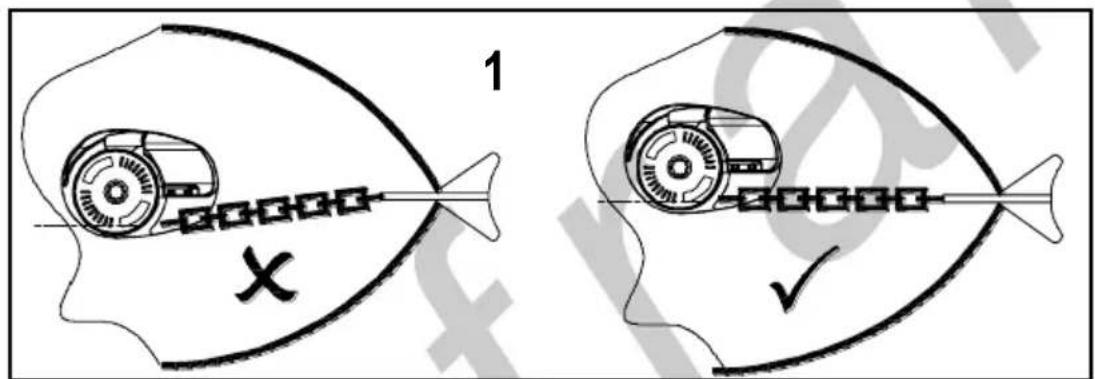
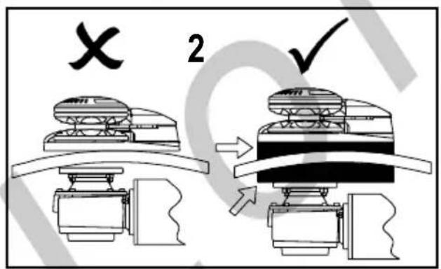

- Bow roller alignment: the precise alignment of the anchor windlass to the bow roller is essential for the correct operation of the anchor windlass.
- The parallelism between deck floors must be guaranteed; should it not occur, duly compensate the difference.
- Chain locker depth: the chain fall into the chain locker must be such that when the chain is completely stored, there must be a minimum of 300 mm. between the underside of the deck and the top of the heaped chain.
- Bow roller height: it must be such to guarantee a chain inclination lower than 5 degrees.

Non-observance of these requirements will cause the malfunctioning of the anchor windlass.
3.5 Prevention from electrolysis
For aluminium boats, it is essential that the anchor windlass be insulated from the deck through a non-conductive gasket (not supplied). In addition, it is important that also the anchor and the chain be insulated from the hull, including chain stopper and fixing systems.

Without these precautions, the electrolysis phenomenon will lead to a rapid corrosion of the anchor windlass.
3.6 Deck thickness
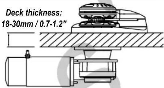
The area of the deck where the capstan is mounted must be solid and resistant so to be able to support the stresses due to the recovery of the anchor. The standard series studs allow an admissible range of deck thickness from 18 to 30 mm. Upon request, different deck thicknesses may be provided (minimum deck thickness is 10mm).
3.7 Deck installation
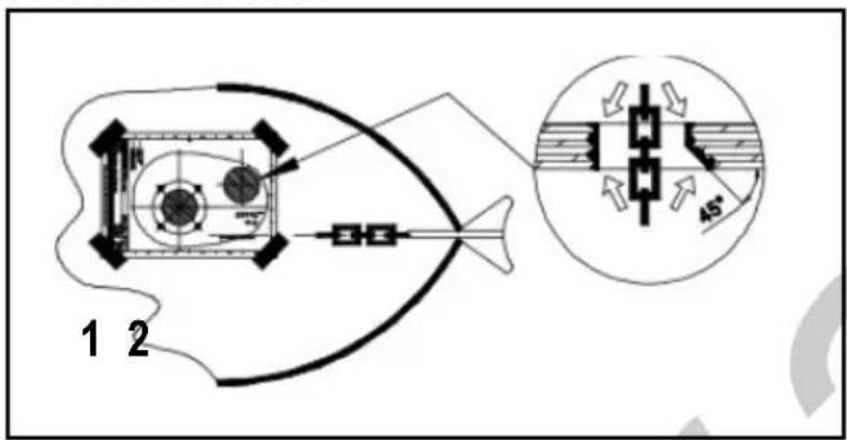
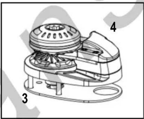
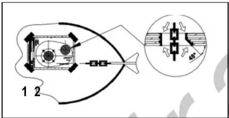
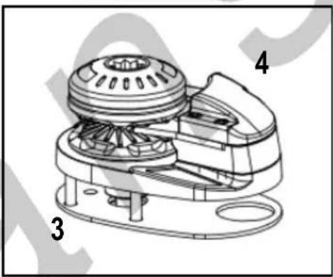
- Place carefully the drilling template on the deck, by ensuring the correct alignment with the bow.
- Mark and drill as indicated in the figure. Let the edges of the holes sharp, while the edge side of the holes of the chain towards the bow must be smoothed for an angle of 45^ degree.
- Clean and place the provided gasket
- Place carefully the upper part of the anchor windlass on the deck.
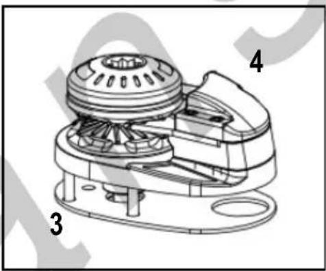
Note:
It is recommended to seal the base of the anchor windlass to the deck by means of silicone glue. Do not use a permanent glue to fix the base of the anchor windlass to the deck since this will make difficult the removal in case of maintenance or intervention.
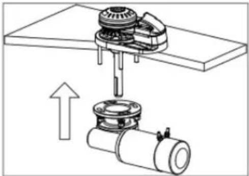
3.8 Under deck installation
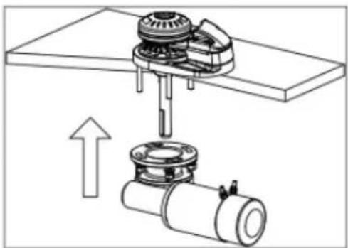
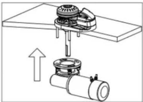
- Grease the main shaft
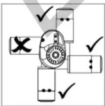
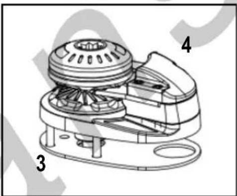
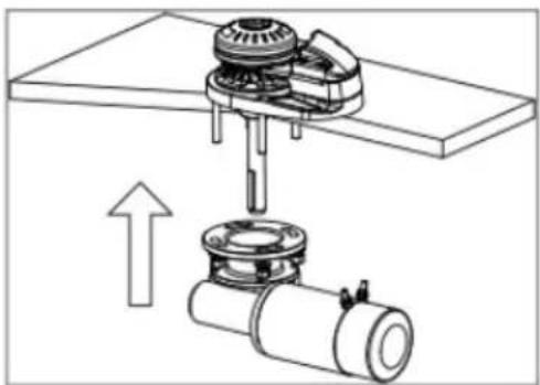
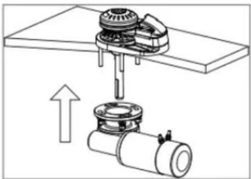
- Join the reducer to the upper part by aligning the motor far from the chain hole.
-
Screw washers and related nuts to the studs by fastening them appropriately.
-
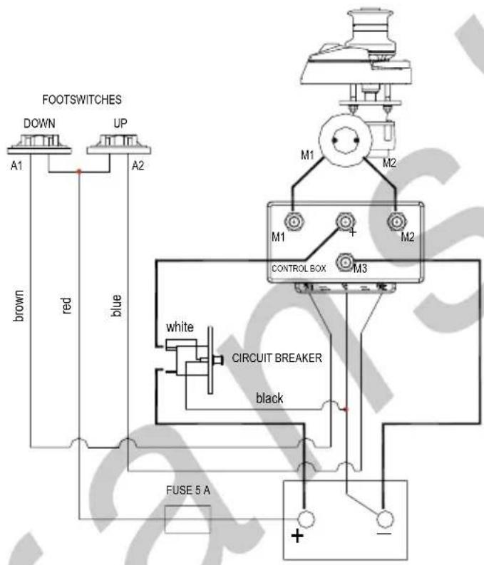
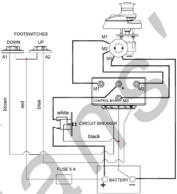
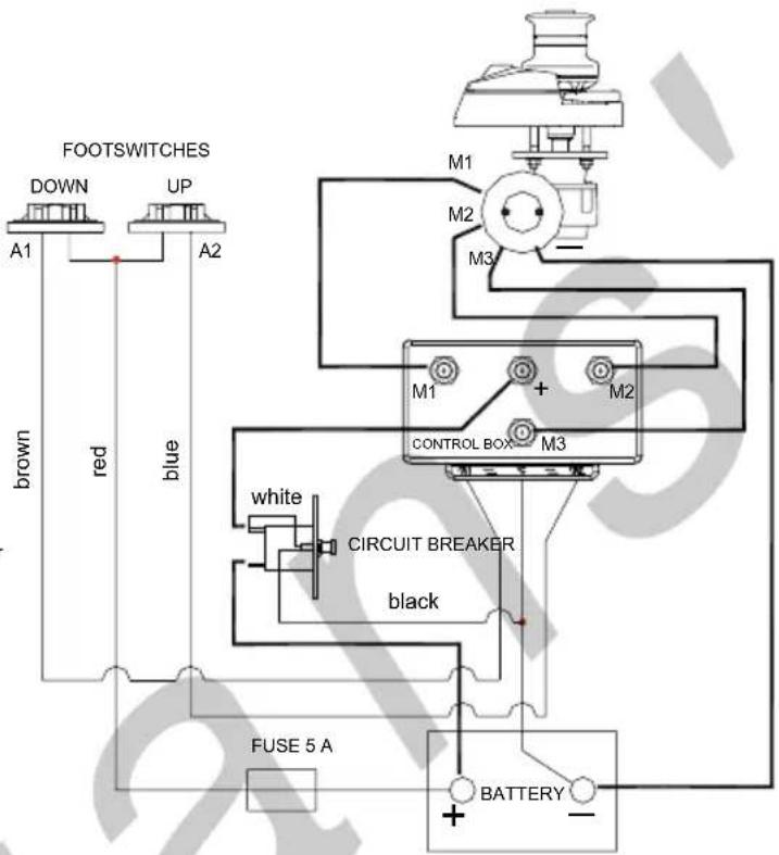
Connect the cables coming from the battery to the electric motor by following the indications of the wiring diagram
-
The installer is responsible to properly protect the motor and the electrical components (such as the control box) from direct water contact. Water damage to the electrical components due to water ingress will void the warranty.
natural_image
Mechanical assembly diagram showing a clamping mechanism with rotating components and an upward arrow (no text or labels)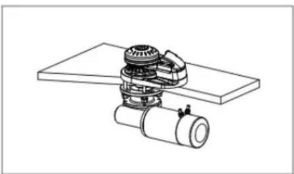
natural_image
Technical line drawing of a mechanical assembly with gears and a cylindrical component (no text or symbols)
ATTENTION! Always disconnect electrical power to the anchor windlass before carrying out any operation.
3.9 Chain insertion
In order to guarantee performances and reliability, it is recommended to use a calibrated chain of the measure corresponding to the gipsy supplied.
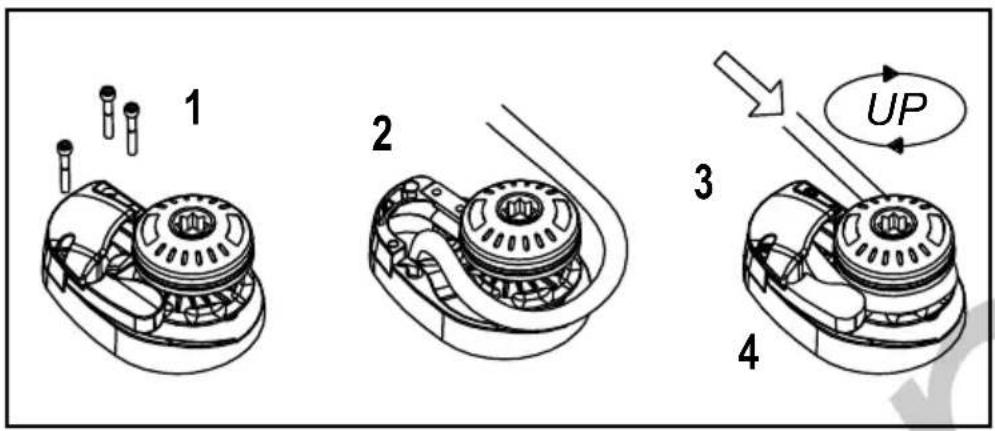
- Remove the covering hood by unscrewing the two seal screws.
- Insert the chain into the hole and fix to a safe point.
- Replace the hood by screwing the fixing screws.
- Wrap the chain in the gipsy.
- Recover all the chain by using the motor, taking care that the chain enters into the gipsy well aligned.

Insert always an articulated joint between the chain and the anchor so that the chain itself does not turn into as spiral.
4 ELECTRICAL SYSTEM
| Model | Motor Power (W) | Voltage (V) | Contactor (A) | Cable sizing according length of cable (positive + negative) | |||
| 0-15 m | 0-50 ft | 15-25 m | 50-75 ft | ||||
| X1/X1 Alu | 500 12 35 16 mm | ^2 | 6 AWG 25 mm | ^2 | 4 AWG | ||
| 800 12 70 16 mm | ^2 | 6 AWG 35 mm | ^2 | 2 AWG | |||
| 1000 12 100 | 25 mm | ^2 | 4 AWG 50 mm | ^2 | 1 AWG | ||
4.1 Electrical cable section
In order to obtain the maximum performances from the anchor windlass and safeguard the electrical system, it is essential that the anchor windlass be wired with cables of sufficient section as suggested in the table.
4.2 Solenoid valves (Control Box)
Place it in a dry place near the capstan.
4.3 Circuit breakers
The circuit breakers recommended by Lofrans' have an intervention curve and not a simple plate value. The switches selected for each model guarantee the correct operation of the system.
4.4 Remote control electric panel board
The remote control electric panel board must be mounted in a comfortable position (such as the deck, the rudder or the cockpit), so that the operator can see the capstan during the manoeuvre. Mount and seal the electric panel board so that the terminals remain in a dry place.
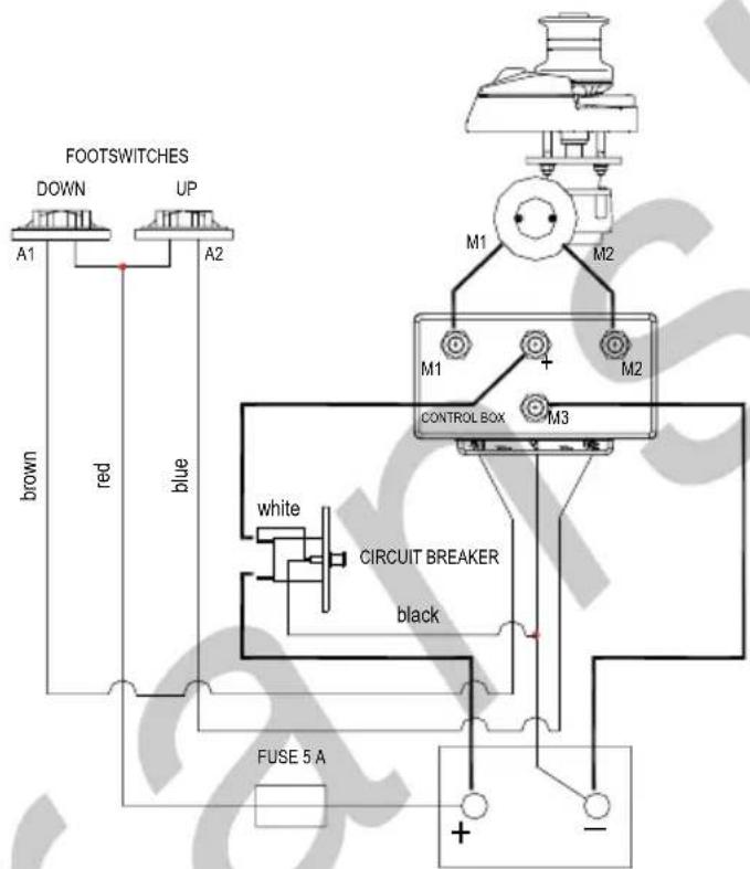
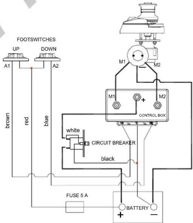
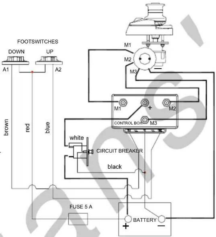
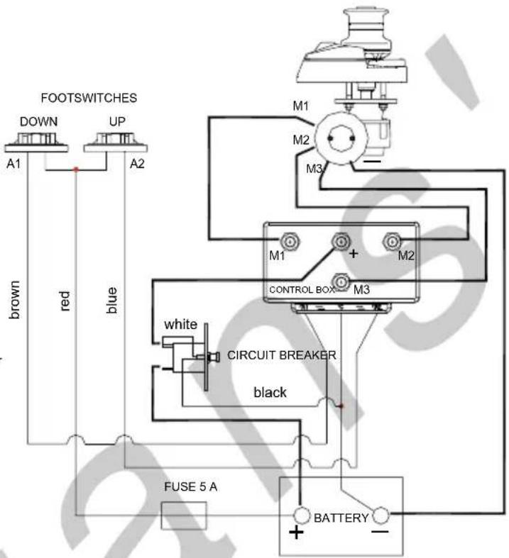
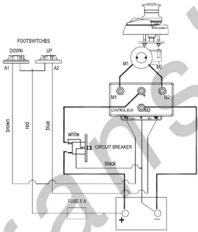
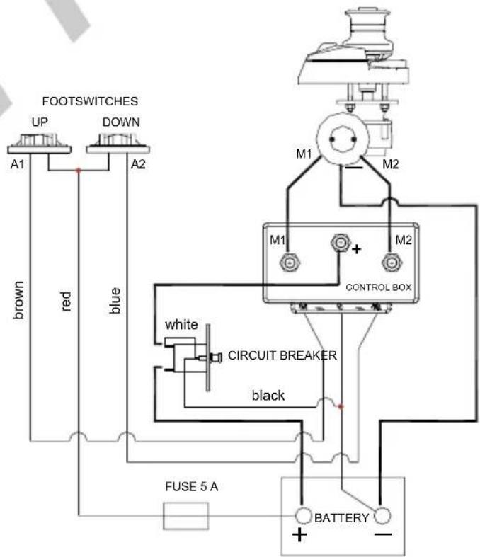
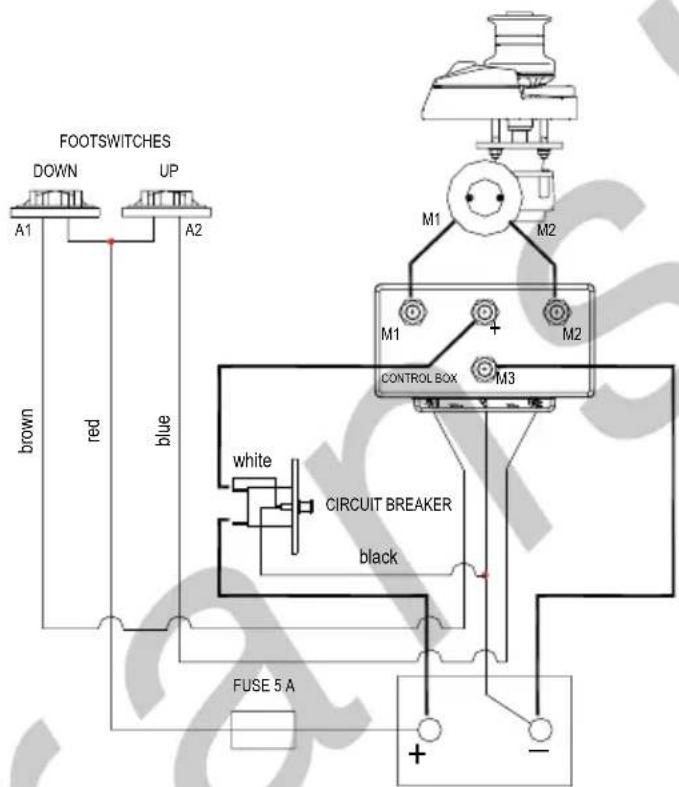
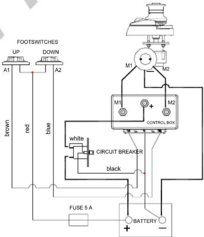
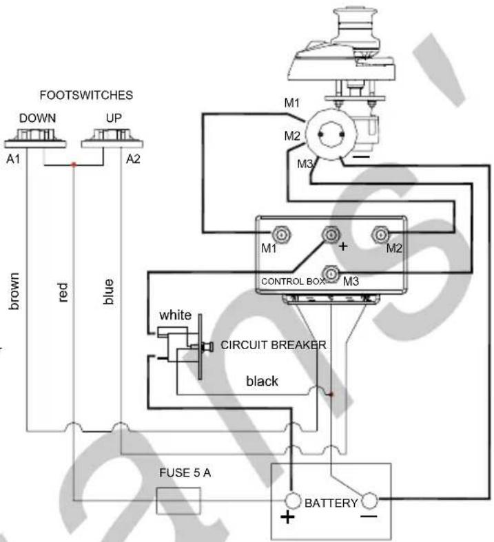
4.5 Wiring Diagram
WIRING DIAGRAM CODE : E0016-A
WIRING DIAGRAM - 2 TERMINALS ELECTRIC MOTOR
WIRING DIAGRAM CODE : E0015-A
WIRING DIAGRAM - 3 TERMINALS ELECTRIC MOTOR
WIRING DIAGRAM CODE : E0017-A
WIRING DIAGRAM - 4 TERMINALS ELECTRIC MOTOR
5 USE OF THE WINDLASS
5.1 Lowering the anchor
Lowering of the anchor can be carried out through the electric control or by gravity:
5.1.1 Lowering the anchor electrically
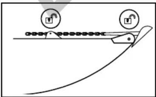
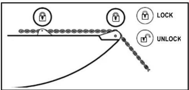
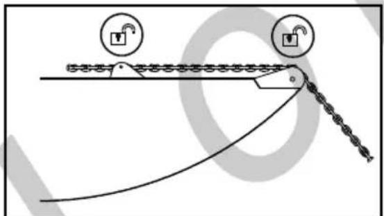
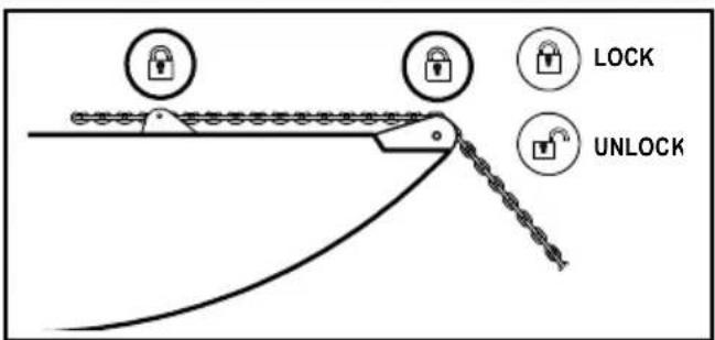
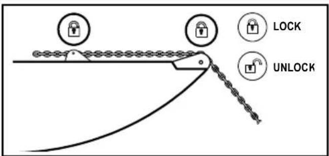
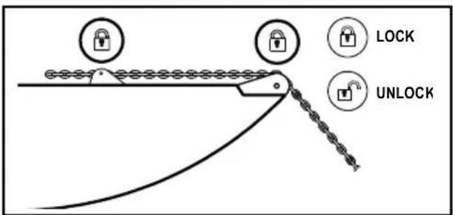
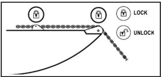
- Make sure that the clutch is tightened. Disengage all chain fixing devices.
- Activate the safety switch
- Press the DOWN button from the control at your disposal. In this way, the lowering of the chain will be perfectly controllable and the unwinding of the chain regular.
- Once the chain is lowered, deactivate the safety switch.
- Engage the chain fixing devices.

During the use of the anchor windlass, do not change directly from one direction to the other but wait until the anchor windlass stops before manipulating the control into the opposite direction.
natural_image
Diagram of a mechanical device with two lock icons and a curved tool, no text or symbols present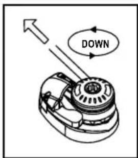

Make sure the anchor windlass is not powered before carrying out manual interventions.
5.1.2 Lowering the anchor by gravity
-
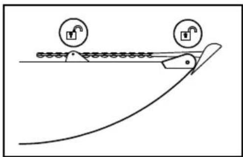
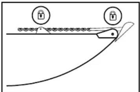
Make sure that the clutch is tightened and then disengage the chain stopper or safety stops.
-
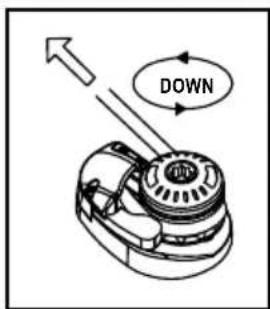
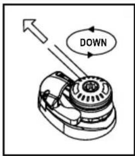
Disengage the clutch gradually through the manoeuvre handle. Note: to adjust the descent speed of the chain act, through the handle, on the clutch. By turning it clockwise, the braking speed of the chain will increase (until complete stop), while by turning it anticlockwise, braking will be reduced.
-
Fix the chain (or the rope) to a strong point.
natural_image
Diagram of a mechanical device with two circular lock symbols above it, showing motion and assembly (no text or labels)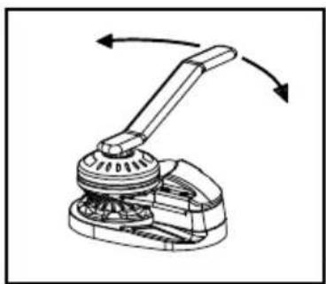
natural_image
Mechanical assembly diagram showing a lever mechanism with rotating arrows (no text or symbols)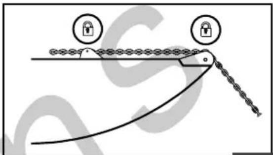

By disengaging completely the clutch, the anchor will be lowered at high speed. Consequently, the fast passage of the chain into the hood and bow roller could damage them. It is recommended always to check the speed.

5.2 Weighing the anchor
-
Make sure that the hydraulic magnetic circuit breaker is activated.
-
Make sure that the clutch is well tightened. Take out the manoeuvre handle from the drum or gipsy.
-
Disengage the chain stopper and safety stops.
-
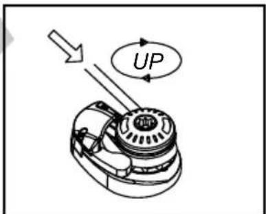
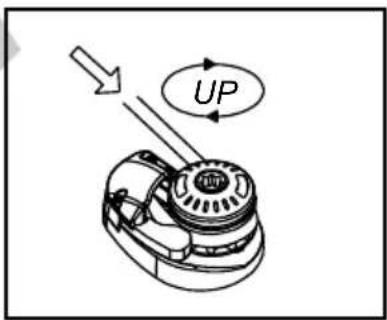
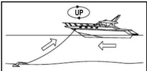
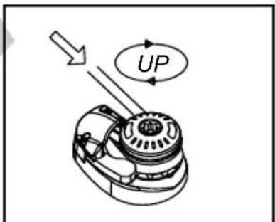
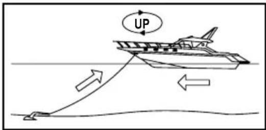
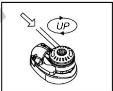
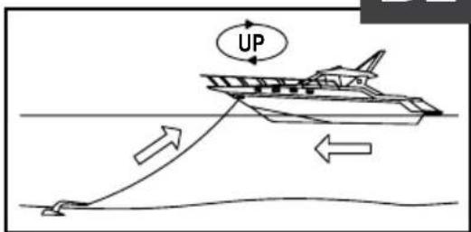
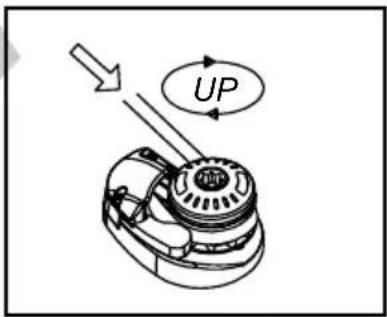
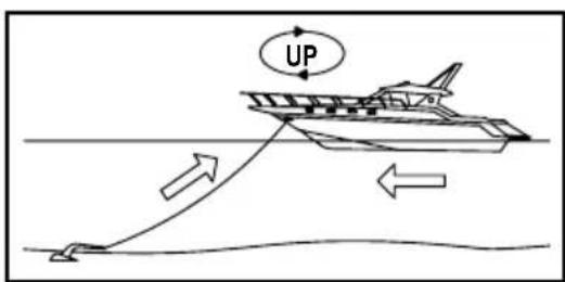
Press the UP button from the control at your disposal until the anchor reaches its position inside the bow roller.
-
Deactivate the hydraulic magnetic circuit breaker.
-
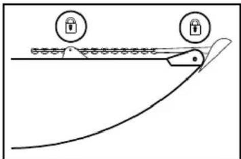
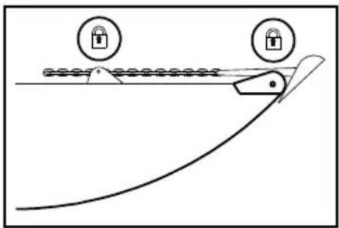
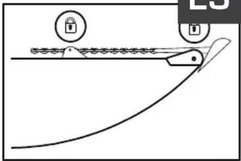
Fix the chain with the chain stopper. In this way a potential damage of the anchor windlass will be avoided as well as unexpected chain releases.
natural_image
Diagram of a mechanical tool interacting with a chain, showing lock and padlock symbols (no text or labels)
Do not carry out the anchor recovery operation by relying only on the onboard batteries. Start the motor of the boat (or the generator) to obtain the necessary electromotive force.
To safeguard the anchor windlass, the hydraulic magnetic circuit breaker is sized so that it comes into action when the anchor windlass is subjected to higher loads than those for which it has been designed. Should it get released owing to an overload reactivate it again and wait some minutes before operating it; waiting for the operation after an overload is necessary to allow the circuits to cool and recover their functionalities.

The hydraulic magnetic circuit breaker does not protect against an excessive increase in the motor temperature due to a prolonged operation of the anchor windlass. Therefore, give the motor the necessary time to cool, to avoid possible damages to the motor thereof.
5.3 Use of the warping drum
The warping drum can be used regardless of the gipsy, to help the mooring manoeuvres.
- Make sure that the anchor is appropriately blocked.
- Insert the manoeuvre handle into the drum and disengage the clutch by turning it clockwise. This operation will make the drum independent of the gipsy.
- Turn clockwise around the drum with three laps of rope.
- By keeping the end of the rope, press the UP button and carry out the mooring manoeuvre.
- Once the manoeuvre is ended, remove the rope from the drum and fasten it to a bollard.
- Deactivate the safety switch.
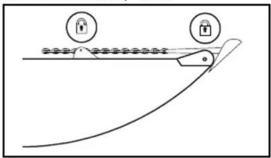
natural_image
Diagram of a mechanical device with lock symbols and a curved track, no text or labels present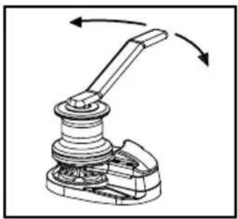
natural_image
Mechanical linkage mechanism diagram showing a lever and base assembly with rotational arrows (no text or symbols)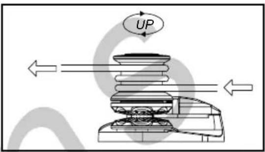

Always remove the manoeuvre handle when not in use.
5.4 Notes for use
During mooring, the load on the chain can be very high due to current, wind and waves.
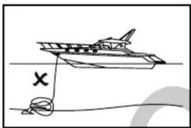
- By paying out the chain, it is necessary to manoeuvre so that the chain is laid down on the seabed without heaping on itself.
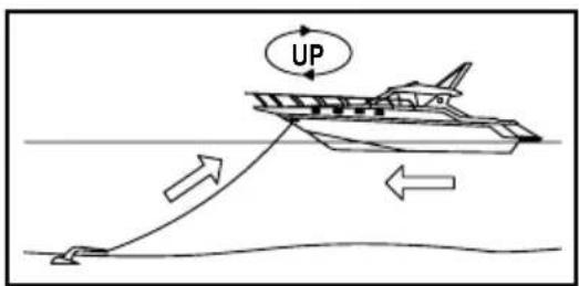
- To ease the recovery and not overloading the capstan, steer up in a way that the boat slowly moves on the vertical of the anchor.
- When the anchor is in the vicinity of the bow roller, slow down the recovery to check at best the insertion of the anchor into the seat.
- The finger is required, only in case that the windlass will manage a rode of chain and rope. If the windlass manages only chain, then the finger is not needed and should be removed, in order to avoid its breakage.
natural_image
Simple line drawing of a boat on water with a rope and a hook, no text or symbols present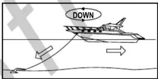

Mooring, do not use the anchor windlass as strong point but always use a chain stopper.

If during recovery, the anchor windlass should block, slip or turn into self-protection mode, check the cause before proceeding.
6 MAINTENANCE
| USE OF THE YACHT (MONTHS) | ||||
| LESS THAN 2 FROM | 2 UP TO 6 MORE THAN | 6 CHARTER | ||
| EVERY 3 MONTHS A - | B A - B | |||
| EVERY 6 MONTHS A - | B | |||
| EVERY 12 MONTHS A - | B - C C C C - D | |||
| EVERY 24 MONTHS D | D E | |||
| EVERY 36 MONTHS | D - E | E | E | |

Follow strictly the maintenance programme. Not meeting the maintenance programme will cause forfeiture of the warranty.

Disconnect power to the anchor windlass before any maintenance.
6.1 Maintenance programme
For obtaining the best performances and the utmost efficiency of the anchor windlass, it is necessary to follow strictly the maintenance programme indicated hereby.
A. Clean all external surfaces and hidden points with fresh water and remove all salt layers. Regarding Dark Version windlasses, they must be cleaned with fresh water once in a week. When it comes to winter storage, the Dark Version windlasses must be covered by a waterproof material.
B. Grease the rotating parts. Particularly, the main shaft threads and clutch cones. Check for evidences of corrosion and mechanical stresses.
C. Check the terminals of the electric motor. Test the voltage drop at the terminals.
D. Replace all gaskets.
E. Remove the anchor windlass from the deck to clean the salt under the base and seal again.
6.2 Gipsy maintenance/replacement
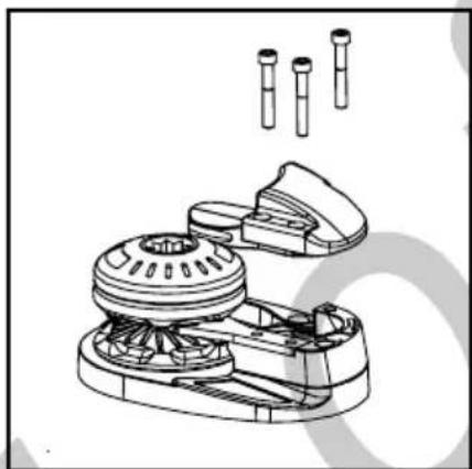
- Remove the hood and the chain pusher by loosening the Allen screws.
- By turning anticlockwise, remove the hand-wheel of the gypsy through the manoeuvre handle.
- Slip off from the shaft the upper clutch cone, the gipsy, and the lower clutch cone.
- Wash with running water. DO NOT USE WATER UNDER PRESSURE.
- Check that there is no evidence of corrosion or mechanical stresses.
- Reassemble by proceeding in the reverse order, remembering to lubricate threads and all moving parts with grease.
natural_image
Technical line drawing of a mechanical device with multiple cylindrical components and a base plate (no text or symbols)
natural_image
Technical line drawing of a mechanical lever mechanism (no text or symbols)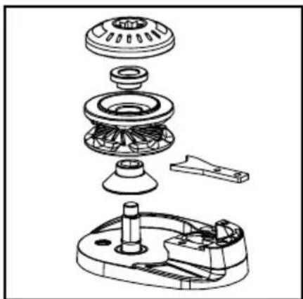
natural_image
Exploded view diagram of a mechanical assembly showing internal components like gears and housing (no text or labels)7 TROUBLESHOOTING
| Problem Possible causes Solution | ||
| 1. The anchor windlass does not work when a control is operated | 1.1 Protection switch in OFF position1.2 Lack of voltage in the system1.3 Failure of the control box1.4 Failure of the control1.5 Failure of the electric motor | 1.1 Check the protection switch and set it in the ON position1.2 Check the charge status of the battery, check connections1.3 Check and possibly replace the control box1.4 Check and possibly replace the control1.5 Measure the electric motor voltage; if it is OK, check the brushes and clean them. If it does not work, replace the electric motor |
| 2. The chain jams frequently | 2.1 The chain locker is not deep enough with respect to the quantity of chain chosen2.2 The chain is not suitable for the gipsy2.3 The chain is not calibrated | 2.1 Position the anchor windlass in the deepest point of the chain locker or reduce the quantity of chain2.2 Change the gipsy2.3 Check the chain: if it does not meet the tolerances, it must be replaced |
| 3. The winch runs slowly and at times jumps the circuit breaker. | 3.1 Section of cables not suitable.3.2 Poor electrical connections.3.3 Dirty brushes.3.4 Water leaks in the electrical engine.3.5 There is no parallelism between upper deck and below deck.3.6 The gearbox has lost oil.3.7 The engine strains in one or both directions.3.8 The winch works only in one direction. | 3.1 Increase the cable section3.2 Check out the connections3.3 Clean the brushes3.4 Replace the electrical engine3.5 Work surfaces and/or add shims to restore parallelism.3.6 (SERVICE) Uninstall the gearbox and check out its condition. Replace damaged parts after discovering the causes of the leak. Also, replace gaskets and screws. Check out also the engine condition, which may have been damaged during the malfunction.3.7(SERVICE) Check out appropriately all connections of the power cables. If they are alright, uninstall the engine (in some cases it is convenient to disassemble also the gearbox). Check out and possibly replace the brushes.3.8 Check out on the control box that between B2-C and B3-C contacts there are 12/24V when the espective buttons are pressed. If this should happen and one of the relays does not work, replace the control box. |
| 4. The electric engine runs but the shaft does not rotate either Up or Down | 4.1 Heavy wear or breakage of teeth of the crown / worm screw.4.2 Breakage of the engine spindle. | 4.1 (SERVICE) Uninstall the winch and replace the broken parts. Check out carefully that pieces or splinters of broken parts did not enter into the oil circuit and have ruined other mechanical parts. (*)4.2(SERVICE) Replacing of the engine. Care must be taken that the broken part did not remain in the hole of the worm screw. (*)(*) Take advantage of this opportunity to replace any other worn parts, especially gaskets, screws, tabs, seeger, and oil. |
| 5. The electric engine runs, the shaft rotates Up, but does not rotate Down | 5.1 The chain locker is tangled;5.2 The chain is of poor quality with burrs and zinc deposits that do not allow the free flow of the links;5.3 The chain was placed in the locker in block and the links are stuck with each other; | 5.1 Check out that immediately after the anchor there is a joint that allows the chain to unfold properly when weighed.5.2 Remove the chain from the locker and inspect it link by link. Intervene with the appropriate tools to make it as loose as possible and free of obstructions.5.3 Lower manually all the chain in a sea bed deep enough to enable it to unfold properly. Retrieve it with the winch. |
| 6. The winch cannot be weighed: the electric engine runs, the shaft runs, but the gypsy is still | 6.1 The gypsy is not closed on the clutch cones and slips under the load effect, or for some reason the closing wheel is at end stroke. Check out all pieces in sequence.6.2 The clutch cones or the gypsy ones are deformed and the clutch hubs are in contact and prevent closure. | 6.1 Check out clutch tightening. If necessary, measure the parts and check out possible deformations. It is possible to add some thickness to stem the problem. Then replace the damaged parts.6.2 Replace the clutch and/or the gypsy |
| 7. The shaft does not run well, is not aligned, and so is the gypsy and/or the bell. | 7.1 The shaft bent because the winch was subjected to an excessive load. | 7.1 Check out that the procedures of use fall within the specifications of the winch.(SERVICE) Uninstall the winch and replace the shaft. Take this opportunity to replace worn parts, gaskets, seeger, tabs and oil. |
| 8. Loss of oil between the engine and the gearbox body | 8.1 The coupling of the engine is loose and causes the worm screw into an irregular rotation, leading to loss of oil from the gasket. | 8.2 (SERVICE) Find the reasons why the screws or nuts have become loose. Uninstall the engine and check out the status of the spindle and the hole of the worm screw. If an oval form of the cylindrical part of the screw is observed (outer hole and diameter) uninstall the winch and repair the damaged parts on the bench. Check out if the oil has entered into the electrical engine. Take this opportunity to replace all gaskets, tabs, seeger, screws, oil, and any worn parts. |
| 9. On installation, it is found that the shaft and the studs are short for a correct coupling with the gearbox. | 9.1 The request referred to the deck thickness was wrong. | 9.1 If the key shaft works in the gearbox along all its length, the fixing studs can be adapted. Otherwise, a longer shaft must be requested. |
| 10. The finger is broken | 10.1 Poor layout of the cable top or rolling of the chain has broken the finger. Check out the suitability of the gypsy to work with the finger. | 10.1 Replace the finger.10.2 In the event that the gypsy cannot work properly with the finger, position the replacement kit (cap). |

8 TECHNICAL DATA
| Motor Power 500W 800W 1000w | |||
| Vessel Lenght Heavy Duty (ft) 20 - 30 | 25-35 30-40 | ||
| Vessel Lenght Light Duty (ft) 30 - 35 | 35-40 35-45 | ||
| Power Supply 12V 12V 12V | |||
| Maximum linear Load/Pull (Kg /lb) | 630 / 1386 700 / 1540 900 / 1980 | ||
| Maximum lift Load/Pull (Kg /lb) | 345 / 759 380 / 836 | 425 / 935 | |
| Max Lift Working Load (Kg /lb) | 95 / 209 | 100 / 220 | 125 / 275 |
| Amps Work Load (A) | 60 | 110 | 120 |
| Max Line Speed (mt./min. / ft/min.) | 26 / 78 | 28 / 84 | 30 / 90 |
| Line Speed (mt./min. / ft/min.) | 23 / 69 | 25 / 75 | 20 / 60 |
| Net weight with Drum (Kg /lb) | 12 / 27 | 14 / 31 | 17 / 38 |
| Net weight Low Profile (Kg /lb) | 11 /25 | 13 / 29 | 16 / 36 |
| Gipsy | 6mm | 7mm | 8mm | ||||||||
| Chain supported | 6mm | 6mm | 3/16” | 7mm | 7mm | 1/4” | 1/4” | 8mm | 8mm | 5/16” | 5/16” |
| ISO | DIN 766 | BBB | ISO | DIN 766 | G4 | BBB | ISO | DIN 766 | G4 | BBB | |
| Rope supported | 12mm - 1/2” | 12mm - 1/2” | 12mm - 1/2” | ||||||||

9 SPARE PARTS
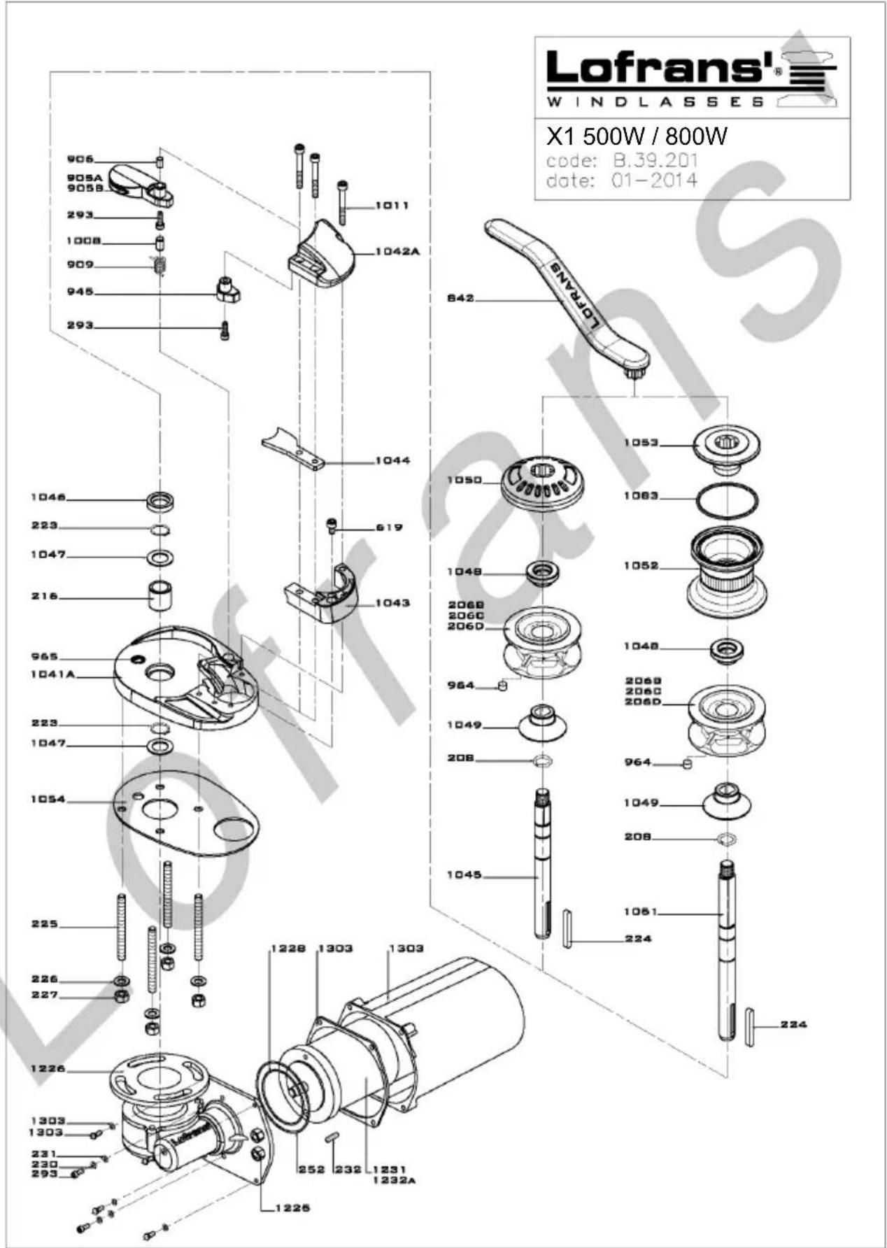
X1 500W / 800W IP67
| Item | Description | Kit | Q.ty |
| 208 | Ring | 1 | |
| 216 | Bush | 1 | |
| 223 | Circlip - 18 Din 471 | Kit D | 2 |
| 224 | Key - 6x6x45 | Kit C | 1 |
| 226 | Washer for M8 screw | Kit B | 4 |
| 227 | Nut - M8 | Kit B | 4 |
| 230 | Spring washer for M5 screw | Kit B | 2 |
| 231 | Washer for M5 screw | Kit B | 2 |
| 232 | Key - 4x4x15 | Kit C | 1 |
| 252 | O Ring 2325 | 1 | |
| 293 | Hd cap screw M5x16 | Kit F | 3 |
| 619 | Hd cap screw M6x10 | Kit B | 1 |
| 906 | Spacer | Kit F | 1 |
| 909 | Spring | Kit F | 1 |
| 945 | Cap | Kit F | 1 |
| 964 | Magnet | Kit S | 1 |
| 965 | Sensor | Kit S | 1 |
| 1008 | Pivot 7x14 | Kit F | 1 |
| 1011 | Hd cap screw M6x40 | Kit B | 3 |
| 1043 | Support | 1 | |
| 1044 | Stripper | 1 | |
| 1046 | Seal 18-30-7 | Kit A | 1 |
| 1047 | Ring | 2 | |
| 1048 | Clutch cone - outer | 1 | |
| 1049 | Clutch cone - inner | 1 | |
| 1050 | Gipsy cap | 1 | |
| 1053 | Nut | 1 | |
| 1054 | Gasket | 1 | |
| 1083 | O Ring 3250 | Kit A | 1 |
| 1225 | PG9 | 2 | |
| 1226 | Gearbox | 1 | |
| 1228 | O Ring 2250 | 1 | |
| 1231 | Electric motor 500W 12V | 1 | |
| 1303 | Complete motor cover kit | Kit Cover | 1 |
| 1041a | Base | 1 | |
| 1042a | Cover | 1 | |
| 1045a | Main shaft without drum | 1 | |
| 1051a | Main shaft with drum | 1 | |
| 1052a | Drum | 1 | |
| 1232a | Electric motor 700W 12V | 1 | |
| 206b | Gipsy chain 6 - 5 pockets | 1 | |
| 206c | Gipsy chain 7 - 6 pockets | 1 | |
| 206d | Gipsy chain 8 - 5 pockets | 1 | |
| 225a | Stud M8x58 | 4 | |
| 842a | Handle | 1 | |
| 905a | Finger | Kit F | 1 |
| 905b | Stainless steel finger | Kit F | 1 |

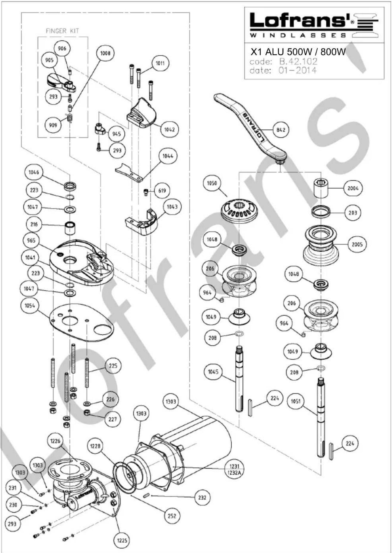
X1 ALU 500W / 800W IP67
| Item | Description | Kit | Q.ty |
| 203 | Seal 35x45x7 | Kit A | 1 |
| 208 | Ring | 1 | |
| 216 | Bush | 1 | |
| 223 | Circlip- 18 Din 471 | Kit D | 2 |
| 224 | Key - 6x6x45 | Kit C | 1 |
| 226 | Washer for M8 screw | Kit B | 4 |
| 227 | Nut - M8 | Kit B | 4 |
| 230 | Spring washer for M5 screw | Kit B | 2 |
| 231 | Washer for M5 screw | Kit B | 2 |
| 232 | Key - 4x4x15 | Kit C | 1 |
| 252 | O Ring 2325 | Kit A | 1 |
| 293 | Hd cap screw M5x16 | Kit F | 1 |
| 619 | Hd cap screw M6x10 | Kit B | 1 |
| 906 | Spacer | Kit F | 1 |
| 909 | Spring | Kit F | 1 |
| 945 | Cap | 1 | |
| 964 | Magnet | Kit S | 1 |
| 965 | Sensor | Kit S | 1 |
| 1008 | Pivot 7x14 | Kit F | 1 |
| 1011 | Hd cap screw M6x40 | Kit B | 3 |
| 1043 | Support | 1 | |
| 1044 | Stripper | 1 | |
| 1046 | Seal 18-30-7 | Kit A | 1 |
| 1047 | Ring | 2 | |
| 1048 | Clutch cone - outer | 1 | |
| 1049 | Clutch cone - inner | 1 | |
| 1050 | Gipsy cap | 1 | |
| 1054 | Gasket | 1 | |
| 1225 | PG9 | 2 | |
| 1226 | Gearbox | 1 | |
| 1228 | O Ring 2250 | Kit A | 1 |
| 1231 | Electric motor 500W 12V | 1 | |
| 1303 | Complete motor cover kit | Kit Cover | 1 |
| 2004 | Clutch nut | 1 | |
| 2005 | Drum | 1 | |
| 1041b | Base | 1 | |
| 1042b | Cover | 1 | |
| 1045a | Main shaft without drum | 1 | |
| 1051a | Main shaft with drum | 1 | |
| 1232a | Electric motor 700W 12V | 1 | |
| 206b | Gipsy chain 6 - 5 pockets | 1 | |
| 206c | Gipsy chain 7 - 6 pockets | 1 | |
| 225a | Stud M8x58 | 4 | |
| 842b | Handle | 1 | |
| 905a | Finger | Kit F | 1 |
| 905b | Stainless steel finger | Kit F | 1 |

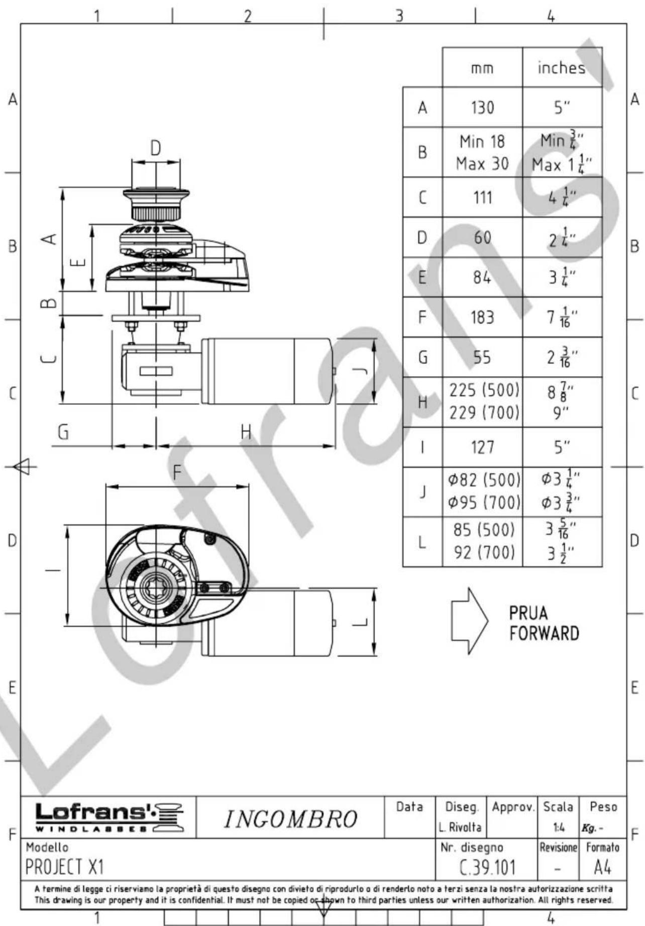
10 OVERALL DIMENSIONS
12 WARRANTY CONDITIONS
Lofrans' guarantees that in a normal use and by meeting the maintenance programmes, the anchor windlass is covered by a warranty for a period of 3 years from the date of purchase by the ultimate user, subject to the conditions, limitations, and exceptions listed hereunder. Any product that proves to be defective in a normal use during this period will be repaired or replaced at the choice of Lofrans'.
12.1 Conditions and limits
- Lofrans' liability will be limited to the repair or replacement of all parts of the product that show material or processing defects.
- Lofrans' is not liable for the wrong choice of the anchor windlass by the purchaser.
-
Lofrans' will not be liable in any whatsoever manner for failures, or any consequent damage deriving from:
-
use of the anchor windlass in an application for which it was not designed or envisaged;
- breakage of the finger due to the operation of the windlass only with chain (in this case finger must not be installed);
- water damage to the electrical components due to water ingress;
- corrosion, degradation by UV rays and wear;
- non-observance of the maintenance plan;
- wrong or unsuitable installation of the product;
- any modification or alteration of the product;
-
conditions of use beyond the specifications and the performances of the product:
-
Except for different directives given directly by Lofrans', any product subject to a warranty request must be returned to Lofrans' which will analyse the problem.
- Cases of galvanic corrosion between the windlass and the hull or the installation voids the warranty.
- The warranty does not cover the accessory costs met for interventions, removal, transport, and installation of the product;
- Maintenance carried out by persons not authorised by Lofrans' will invalidate this warranty;
- The Lofrans' products are intended to be used only in a marine environment. Lofrans' is not liable should these products be used differently.
12.2 Exceptions
The cover under warranty of the following components is limited to a period of one year from the date of purchase by the ultimate user:
- Electric motors and related electric equipment
- Electronic controls
- Hydraulic pumps, valves, and actuators
- Gaskets and seals
- Products used on charter boats.
12.3 Liability
The liability of Lofrans' on this warranty is intended dependant on meeting the regulations and laws in force.
Lofrans' is not liable for any other kind, such as:
- Any loss of turnover, advances, or direct or indirect profits, or any other financial loss;
- Damages, costs or expenses payable to third parties;
- Damages to yachts or equipment;
- Death or personal injuries (unless caused by negligence of Lofrans').
Certain States and Countries do not allow the exclusion or limitation of incidental or consequential damages, therefore the aforementioned limitations or exclusions might not be applicable.
12.4 Procedure
Every request for intervention under warranty will be made promptly and in writing by the ultimate user to the local Lofrans' assistance centre.
12.5 Clause of termination
If any whatsoever clause of this warranty will be invalidated by a Judge or other competent authority, the validity of the remaining clauses of this warranty and the rest of the clause in question will not be affected.
12.6 Compliance
This warranty is governed by the laws and in compliance with the Italian Laws or the State or Country in which the ultimate user is domiciled at the time of purchase of the product.
Gentile cliente,
Nota:
natural_image
Mechanical assembly diagram showing a motor and cylinder with an upward arrow indicating motion (no text or symbols)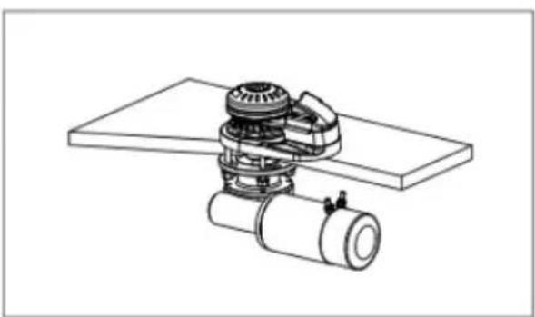
natural_image
Technical line drawing of a mechanical assembly with gears and a cylindrical component (no text or symbols)
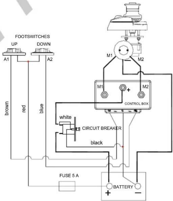
WIRING DIAGRAM - 2 TERMINALS ELECTRIC MOTOR
WIRING DIAGRAM CODE : E0015-A
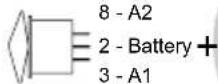
ROCKER SWITCH TYPE C
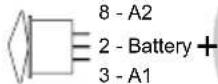
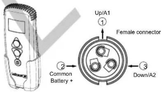
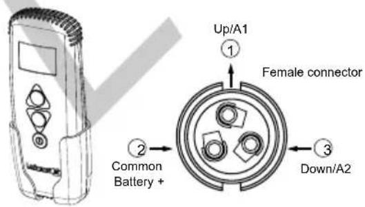
HAND HELD REMOTE
CONTROL THETIS 1002
WIRING DIAGRAM - 3 TERMINALS ELECTRIC MOTOR
WIRING DIAGRAM CODE : E0017-A
WIRING DIAGRAM - 4 TERMINALS ELECTRIC MOTOR
IT
5 USO DEL SALPA ANCORA
5.1 Calare l'ancora
natural_image
Diagram of a mechanical device with two lock icons and a curved tool, no text or symbols present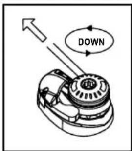

natural_image
Simple line drawing of a mechanical device with two lock icons and a curved base (no text or symbols)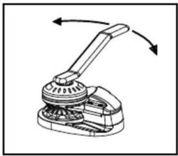
natural_image
Mechanical assembly diagram showing a lever mechanism with bidirectional arrows indicating rotation (no text or symbols)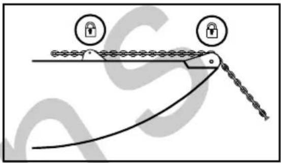
natural_image
Diagram of a mechanical linkage system with two lock icons and a curved chain (no text or symbols)
natural_image
Diagram showing a curved ramp with two lock icons above it, indicating lock status (no text or symbols present)
natural_image
Diagram of a mechanical linkage or cable with two lock icons and a curved base, no text or symbols present.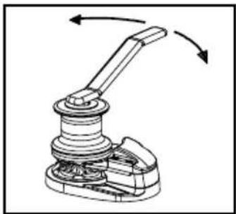
natural_image
Mechanical lever mechanism diagram showing rotational motion with no text or symbols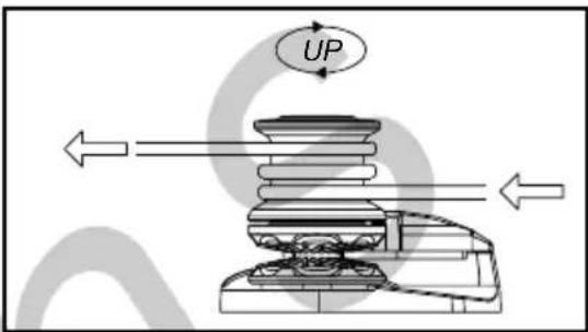

natural_image
Simple line drawing of a boat with a rope and a hook, no text or symbols present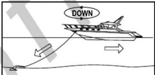

natural_image
Technical line drawing of a mechanical device with multiple cylindrical components and a central hub (no text or symbols)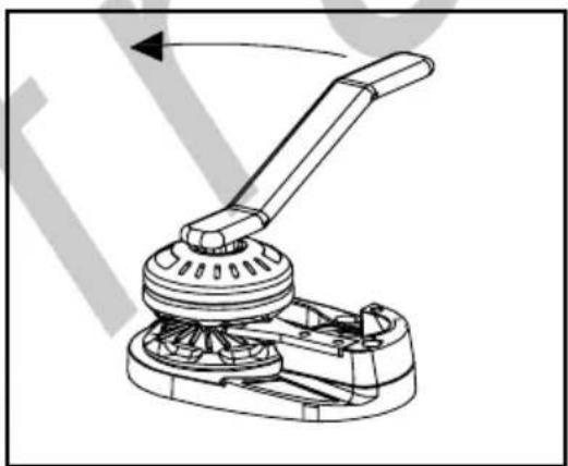
natural_image
Mechanical device diagram showing a lever mechanism with rotating shaft and housing (no text or symbols)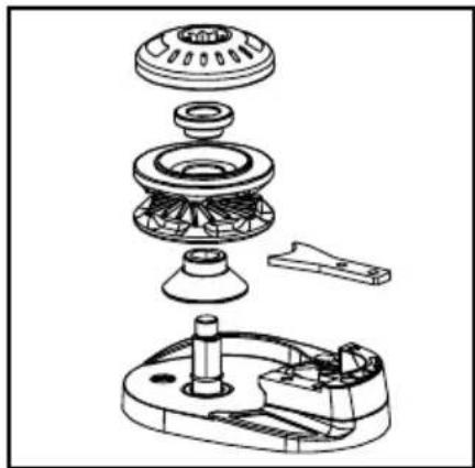
natural_image
Exploded view diagram of a mechanical assembly showing internal components like gears and housing (no text or labels)7 INDIVIDUAZIONE GUASTI
Remarque:
natural_image
Mechanical assembly diagram showing a motor and cylinder with an upward arrow indicating motion (no text or symbols)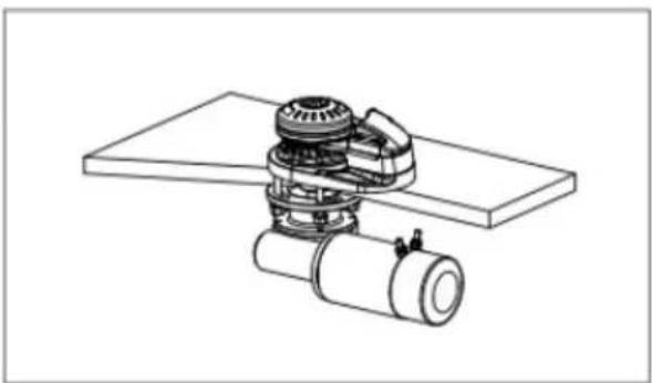
natural_image
Technical line drawing of a mechanical assembly with a cylindrical component and a fan-like structure (no text or symbols)
WIRING DIAGRAM - 2 TERMINALS ELECTRIC MOTOR
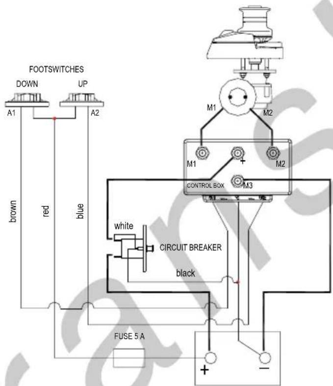
FR
WIRING DIAGRAM CODE : E0015-A
WIRING DIAGRAM - 3 TERMINALS ELECTRIC MOTOR
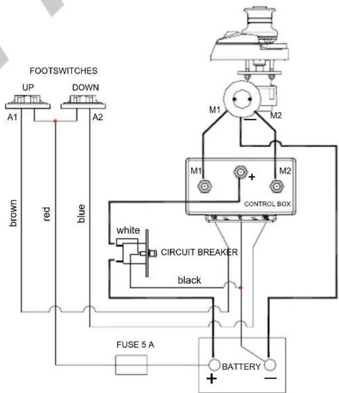
WIRING DIAGRAM CODE : E0017-A
WIRING DIAGRAM - 4 TERMINALS ELECTRIC MOTOR
5 UTILISATION DU GUINDEAU
5.1 Jeter l'ancre
natural_image
Diagram of a mechanical device with two lock icons and a curved tool, no text or symbols present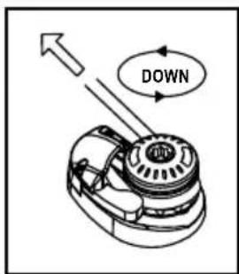

natural_image
Simple line drawing of a tool interacting with a surface, showing two lock icons above the handle (no text or symbols)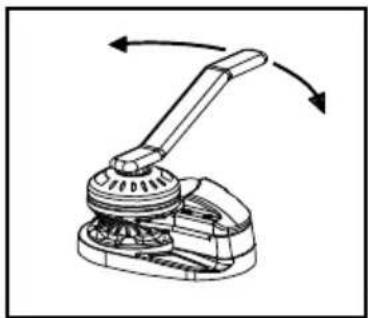
natural_image
Mechanical device with lever mechanism and directional arrows indicating rotation (no text or symbols)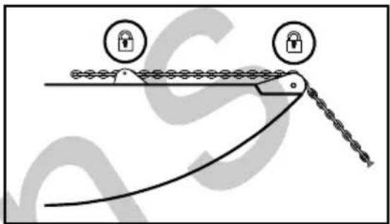


natural_image
Diagram of a mechanical device with two lock icons and a curved tool, no text or symbols present
natural_image
Diagram of a mechanical device with lock symbols and a curved track, no text or labels present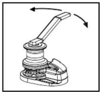
natural_image
Mechanical linkage mechanism diagram showing rotational motion with no text or symbols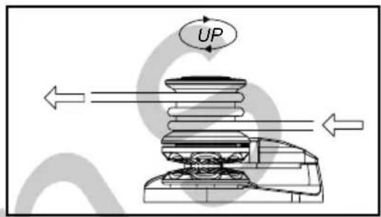

natural_image
Simple line drawing of a boat with a rope tied to a hook, no text or symbols present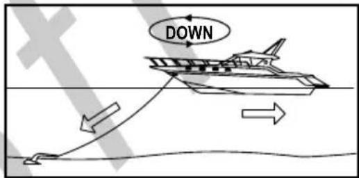

natural_image
Technical line drawing of a mechanical device with multiple cylindrical components and a base plate (no text or symbols)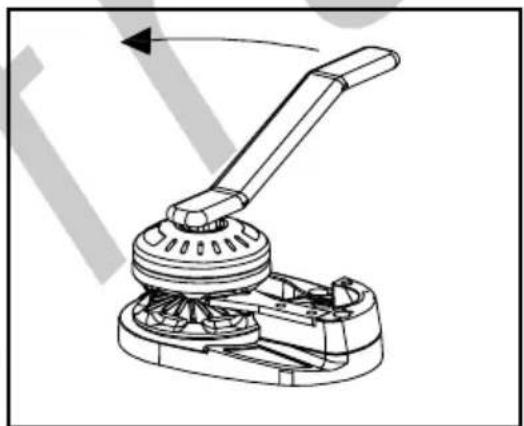
natural_image
Mechanical device diagram showing a lever mechanism with rotating shaft and base (no text or symbols)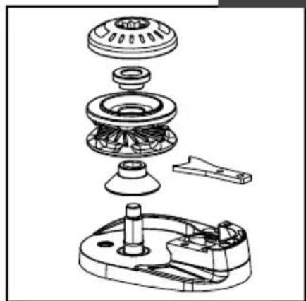
natural_image
Exploded view diagram of a mechanical assembly showing internal components like gears and housing (no text or labels)7 TROUBLESHOOTING
3.7 Auf Deck Installation
Anmerkung:
natural_image
Mechanical assembly diagram showing a clamping mechanism with a rotating component and an upward arrow (no text or labels)
natural_image
Technical line drawing of a mechanical assembly with gears and shafts (no text or symbols)
WIRING DIAGRAM - 2 TERMINALS ELECTRIC MOTOR
WIRING DIAGRAM CODE : E0015-A
ROCKER SWITCH TYPE C
HAND HELD REMOTE
CONTROL THETIS 1002
WIRING DIAGRAM - 3 TERMINALS ELECTRIC MOTOR
WIRING DIAGRAM CODE : E0017-A
WIRING DIAGRAM - 4 TERMINALS ELECTRIC MOTOR
5 BEDIENUNG DER ANKERWINDE
5.1 Den Anker fallen lassen

natural_image
Simple line drawing of a tool interacting with a curved surface, no text or symbols present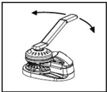
natural_image
Mechanical assembly diagram showing a lever mechanism with rotating arrows (no text or symbols)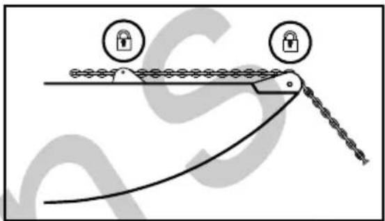
natural_image
Diagram of a mechanical linkage system with two lock icons and a curved chain (no text or labels)
natural_image
Diagram of a mechanical device with two lock icons and a curved tool, no text or symbols present
natural_image
Diagram of a mechanical device with two lock icons and a curved tool, no text or symbols present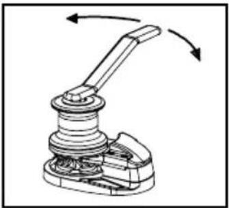
natural_image
Mechanical lever mechanism diagram showing rotational motion with no text or symbols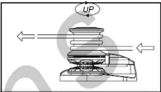

natural_image
Simple line drawing of a boat with a rope tied to a hook, no text or symbols present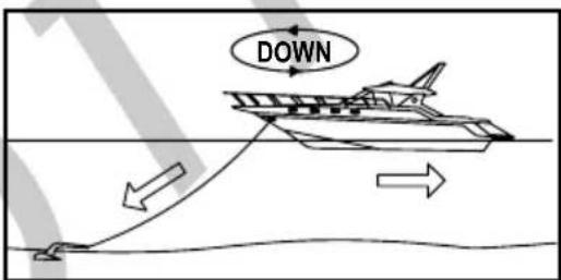

natural_image
Technical line drawing of a mechanical device with multiple cylindrical components and a central hub (no text or symbols)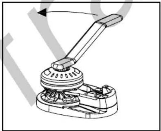
natural_image
Mechanical assembly diagram showing a lever mechanism with rotating shaft and base (no text or symbols)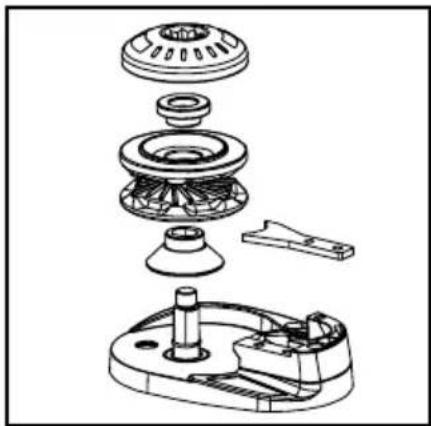
natural_image
Exploded view diagram of a mechanical assembly showing internal components like gears and housing (no text or labels)7 TROUBLESHOOTING
PRODUCTO CONFORME A LAS NORMAS CE
1 INTRODUCTION
natural_image
Mechanical assembly diagram showing a motor and cylinder with an upward arrow indicating motion (no text or symbols)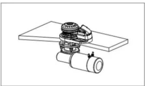
natural_image
Technical line drawing of a mechanical assembly with gears and a cylindrical component (no text or symbols)
Place it in a dry place near the capstan.
4.3 Circuit breaker
WIRING DIAGRAM - 2 TERMINALS ELECTRIC MOTOR
WIRING DIAGRAM CODE : E0015-A
WIRING DIAGRAM - 3 TERMINALS ELECTRIC MOTOR
WIRING DIAGRAM CODE : E0017-A
WIRING DIAGRAM - 4 TERMINALS ELECTRIC MOTOR
5 USO DEL MOLINETE
5.1 Echar el ancla

natural_image
Diagram of a mechanical device with two lock icons and a curved track, no text or symbols present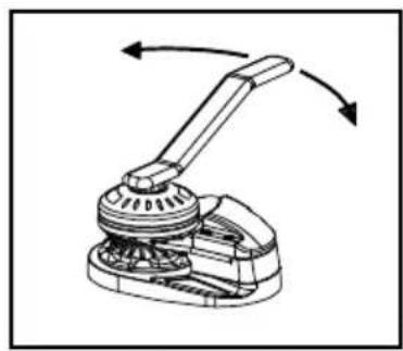
natural_image
Mechanical device with lever mechanism and directional arrows indicating rotation (no text or symbols)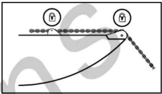
natural_image
Diagram of a mechanical linkage system with two lock icons and a curved chain (no text or symbols)

natural_image
Diagram of a mechanical device with lock symbols and a curved track, no text or labels present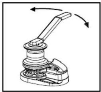
natural_image
Mechanical linkage assembly diagram showing a lever mechanism with rotational arrows (no text or labels)

natural_image
Simple line drawing of a boat with a rope tied to a small object, no text or symbols present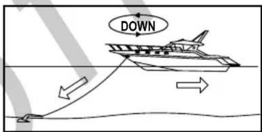

natural_image
Technical line drawing of a mechanical device with multiple cylindrical components and a base plate (no text or symbols)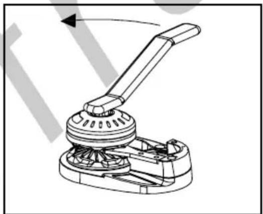
natural_image
Technical line drawing of a mechanical lever mechanism (no text or symbols)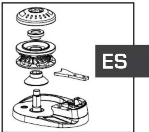
natural_image
Exploded view diagram of a mechanical assembly with labeled component ES (no text or symbols beyond label)

- Verricelli Verticali
- Vertical Windlasses
- X1 - X1 ALU - X1 Dark Version
- Dear Customer,
- Lofrans© copyright, 2024. All rights reserved.
- TABLE OF CONTENTS
- INTRODUCTION 3
- SAFETY INFORMATION 3
- INSTALLATION 4
- USE OF THE WINDLASS 8
- MAINTENANCE 10
- TROUBLESHOOTING 11
- TECHNICAL DATA 13
- SPARE PARTS 14
- OVERALL DIMENSIONS 18
- DRILLING TEMPLATE 19
- WARRANTY CONDITIONS 20
- PRODUCT COMPLIANT WITH EC REGULATIONS
- INTRODUCTION
- Purpose of the manual
- DANGER!
- ATTENTION!
- Assistance
- Receipt and Storage
- SAFETY INFORMATION
- INSTALLATION
- Contents of the package
- Equipment necessary for installation
- Recommended accessories
- General requirements for installation
- Prevention from electrolysis
- Deck thickness
- Deck installation
- Note:
- Under deck installation
- Chain insertion
- Electrical cable section
- Solenoid valves (Control Box)
- Circuit breakers
- Remote control electric panel board
- Wiring Diagram
- USE OF THE WINDLASS
- Lowering the anchor
- Lowering the anchor electrically
- Lowering the anchor by gravity
- Weighing the anchor
- Use of the warping drum
- Notes for use
- Maintenance programme
- Gipsy maintenance/replacement
- TROUBLESHOOTING
- WARRANTY CONDITIONS
- Conditions and limits
- Exceptions
- Liability
- Procedure
- Clause of termination
- Compliance
- Gentile cliente,
- Nota:
- USO DEL SALPA ANCORA
- Calare l'ancora
- INDIVIDUAZIONE GUASTI
- Remarque:
- UTILISATION DU GUINDEAU
- Jeter l'ancre
- Anmerkung:
- BEDIENUNG DER ANKERWINDE
- Den Anker fallen lassen
- PRODUCTO CONFORME A LAS NORMAS CE
- Circuit breaker
- USO DEL MOLINETE
- Echar el ancla
Brand : Lofrans
Model : X1
Category : Electric winch