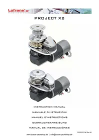
Project X2 - Electric winch Lofrans - Free user manual and instructions
Find the device manual for free Project X2 Lofrans in PDF.



| Brand | Lofrans |
| Model | Project X2 |
| Product type | Electric winch (windlass) |
| Rated power | 700 W or 1000 W (12/24 V) |
| Supply voltage | 12 V or 24 V |
| Power consumption | 70-110 A (12 V), 40-60 A (24 V) |
| Recovery speed | 16 to 25 m/min |
| Electric drop speed | 45 m/min |
| Maximum instantaneous pull | Approx. 900 kg |
| Weight | 19 kg |
| Motor type | Waterproof IP66 |
| Gypsy | Nickel-plated finish, compatible with 8 mm (5/16") HT/BBB chain and 16 mm (5/8") rope |
| Base bearing | AISI 440 stainless steel |
| Finish | Standard chrome-plated |
| Drum | Independent from gypsy |
| Clutch | Cone type, manual |
| Manual emergency button | Yes |
| Electrical protection | Lofrans magnetic-thermal switch (70 A/35 A/100 A depending on version) |
| Warranty | 2 years (subject to registration within 30 days) |
| Recommended maintenance | Freshwater cleaning, greasing of rotating parts, checking connections |
| Intended use | Boats from 10 to 14 meters |
Frequently Asked Questions - Project X2 Lofrans
User questions about Project X2 Lofrans
0 question about this device. Answer the ones you know or ask your own.
Ask a new question about this device
Download the instructions for your Electric winch in PDF format for free! Find your manual Project X2 - Lofrans and take your electronic device back in hand. On this page are published all the documents necessary for the use of your device. Project X2 by Lofrans.
USER MANUAL Project X2 Lofrans
MANUEL D'INSTRUCTIONS
GEBRAUCHSANWEISUNG
| Project X2 presentation Pg.3 Removing the finger Pg.5 |
| Safety information Pg.3 Limited international warranty Pg.5 |
| Windlass wiring minimum requirements Pg.3 Appendix Pg.5 |
| Installation general requirements Pg.3 Wiring diagram Pg.18 |
| Installation procedure Pg.3 Pictures Pg.19 |
| Test procedure Pg.3 Exploded drawings Pg.20 |
| Use of the windlass |
| Maintenance program |
SOMMARIO
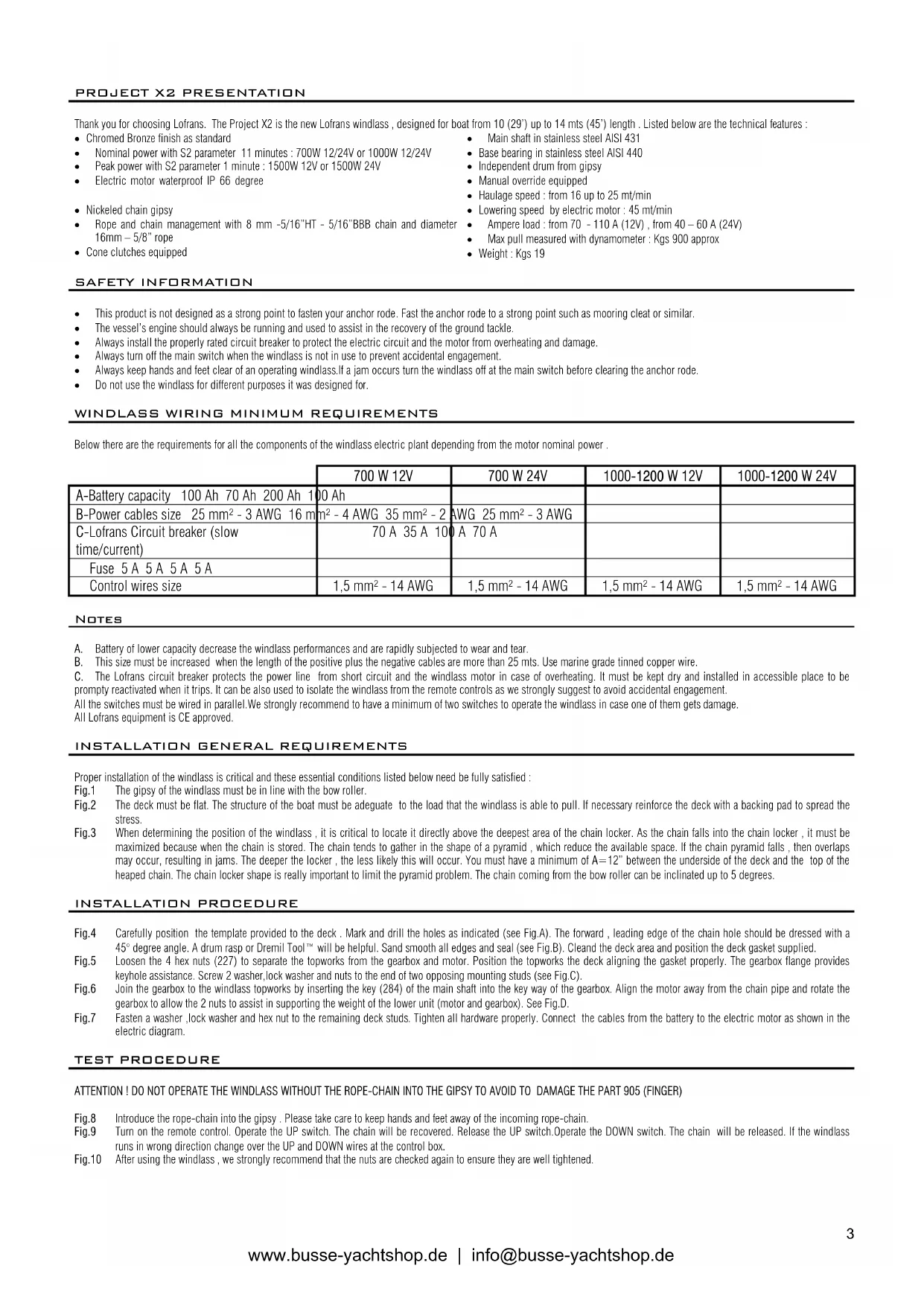
Thank you for choosing Lofrans . The Project X2 is the new Loftrans windlass , designed for boat from 10 (29 ' ) up to 14 mts (45 ' ) length . Listed below are the technical features :
- Chromed Bronze finish as standard
Main shaft in stainless steel AISI 431
Nominal power with S2 parameter 11 minutes : 700W 12/24V or 1000W 12/24V - Base bearing in stainless steel AISI 440
Peak power with S2 parameter 1 minute: 1500W 12V or 1500W 24V - Independent drum from gipsy
Electric motor waterproof IP 66 degree - Manual override equipped
- Nickeled chain gipsy
Haulage speed: from 16 up to 25 mt/min - Rope and chain management with 8 mm -5/16"HT - 5/16"BBB chain and diameter 16mm - 5/8" rope
- Lowering speed by electric motor : 45 mt/min
- Ampere load : from 70 - 110 A (12V), from 40 - 60 A (24V)
Cone clutches equipped
Max pull measured with dynamometer : Kgs 900 approx
Weight:Kgs 19
SAFETY INFORMATION
This product is not designed as a strong point to fasten your anchor rode. Fast the anchor rode to a strong point such as mooring cleat or similar.
The vessel's engine should always be running and used to assist in the recovery of the ground tackle.
Always install the properly rated circuit breaker to protect the electric circuit and the motor from overheating and damage.
Always turn off the main switch when the windlass is not in use to prevent accidental engagement.
Always keep hands and feet clear of an operating windlass. If a jam occurs turn the windlass off at the main switch before clearing the anchor rode.
- Do not use the windlass for different purposes it was designed for.
WINDCLASS WIRING MINIMUM REQUIREMENTS
Below there are the requirements for all the components of the windlass electric plant depending from the motor nominal power .
| 700 W 12V | 700 W 24V | 1000-1200 W 12V | 1000-1200 W 24V | |
| A-Battery capacity 100 Ah 70 Ah 200 Ah 100 Ah | ||||
| B-Power cables size 25 mm² - 3 AWG 16 m | m² - 4 AWG 35 mm² - 2 | AWG 25 mm² - 3 AWG | ||
| C-Loftrans Circuit breaker (slow time/current) | 70 A 35 A 100 A 70 A | |||
| Fuse 5 A 5 A 5 A 5 A | ||||
| Control wires size | 1,5 mm² - 14 AWG | 1,5 mm² - 14 AWG | 1,5 mm² - 14 AWG | 1,5 mm² - 14 AWG |
NOTES
A. Battery of lower capacity decrease the windlass performances and are rapidly subjected to wear and tear.
B. This size must be increased when the length of the positive plus the negative cables are more than 25 mts. Use marine grade tinned copper wire.
C. The Lofans circuit breaker protects the power line from short circuit and the windlass motor in case of overheating. It must be kept dry and installed in accessible place to be prompty reactivated when it trips. It can be also used to isolate the windlass from the remote controls as we strongly suggest to avoid accidental engagement.
All the switches must be wired in parallel. We strongly recommend to have a minimum of two switches to operate the windlass in case one of them gets damage.
All Loftrans equipment is CE approved.
INSTALLATION GENERAL REQUIREMENTS
Proper installation of the windlass is critical and these essential conditions listed below need be fully satisfied :
Fig.1 The gipsy of the windlass must be in line with the bow roller.
Fig.2 The deck must be flat. The structure of the boat must be adequate to the load that the windlass is able to pull. If necessary reinforce the deck with a backing pad to spread the stress.
Fig.3 When determining the position of the windlass, it is critical to locate it directly above the deepest area of the chain locker. As the chain falls into the chain locker, it must be maximized because when the chain is stored. The chain tends to gather in the shape of a pyramid, which reduce the available space. If the chain pyramid falls, then overlaps may occur, resulting in jams. The deeper the locker, the less likely this will occur. You must have a minimum of A = 12 between the underside of the deck and the top of the heaped chain. The chain locker shape is really important to limit the pyramid problem. The chain coming from the bow roller can be inclined up to 5 degrees.
INSTALLATION PROCEDURE
Fig.4 Carefully position the template provided to the deck . Mark and drill the holes as indicated (see Fig.A). The forward , leading edge of the chain hole should be dressed with a 45^ degree angle. A drum rasp or Dremil Tool will be helpful. Sand smooth all edges and seal (see Fig.B). Cleand the deck area and position the deck gasket supplied.
Fig.5 Loosen the 4 hex nuts (227) to separate the topworks from the gearbox and motor. Position the topworks the deck aligning the gasket properly. The gearbox flange provides keyhole assistance. Screw 2 washer, lock washer and nuts to the end of two opposing mounting studs (see Fig.C).
Fig.6 1
Fig.7 Fasten a washer, lock washer and hex nut to the remaining deck studs. Tighten all hardware properly. Connect the cables from the battery to the electric motor as shown in the electric diagram.
TEST PROCEDURE
ATTENTION I DO NOT OPERATE THE WINDCLASS WITHOUT THE ROPE-CHAIN INTO THE GIPSY TO AVOID TO DAMAGE THE PART 905 (FINGER)
Fig.8 Introduce the rope-chain into the gipsy . Please take care to keep hands and feet away of the incoming rope-chain.
Fig.9 Tn on the rme trol. ope the UP swnh. h ch wll be recoed. Rease the UP switch. Operate the DOWN switch. The chain will be released. If the windlass runs in wrong direction change over the UP and DOWN wires at the control box.
Fig.10 After using the windlass, we strongly recommend that the nuts are checked again to ensure they are well tightened.
USE OF THE WINDCLASS
The basic operations you need to know are lowering and raising the anchor by electric motor. This product is cone clutch-equipped which allows to you to lower the anchor without using the electric motor. Lofrans strongly recommend to use the chain stopper in conjunction with this windlass. The chain stopper is a device which is normally installed on the boat and will keep your chain in place on deck. It must be used to secure the anchor after anchoring.
OPERATION FIRST THEN ...
| 1. USE OF THE CLUTCH ON THE LOW PROFILE MODEL | - | To disengage the clutch insert the handle (272) into the star-shaped slot on the gipsy cap (918) and loosen it. To engage the clutch again tight the gipsy can until you cannot move the handle any more. Anchor and/or chain provide resistance during the tightening. |
| 2. USE OF THE CLUTCH ON THE STANDARD MODEL | - | To disengage the clutch insert the handle (272) supplied into the clutch nut (912) and loosen it. To engage the clutch tighten it until you cannot move the handle any more. |
| 3. LOWERING THE ANCHOR BY THE ELECTRIC MOTOR | · Disengage the Chain stopper · Check if the Clutch is engaged · Turn On the Circuit breaker | Simple push the button DOWN. You will have always a perfect control of the operation, which can be interrupted any moment by releasing the button DOWN. |
| 4. AFTER ANCHORING | · Engage the Chain stopper · Engage the Clutch · Turn Off the Circuit breaker | If you have all chain, reduce the windlass load by engaging the chain stopper. If using a combination of rope and chain, fix the rope to a strong point such as a cleat. |
| 5. RAISING THE ANCHOR | · Disengage the Chain stopper · Check if the Clutch is engaged · Turn On the Circuit breaker | Start the engine of the boat. Push the button UP while with the boat at minimum speed going towards the anchoring point. Do not use the windlass to pull the boat to the anchor. Release the button UP to stop the operation. Pay attention to the speed of the anchor, which may damage the bow of your boat. In the event that the anchor becomes stranded and the Lofrans circuit breaker trips, wait several minutes before re-setting and try once more. Should the circuit breaker trip again, we suggest to fix the rope or chain to a cleats and then use the boat engine to break the anchor loose. |
| 6. DURING THE NAVIGATION | · Engage the Chain stopper · Engage the Clutch · Turn Off the Circuit breaker | Windlass must not be used as the sole means of securing the anchor to the bow fitting. Anchors should be independently secured to prevent accidental release. Use a chain stopper or a lanyard to do that. |
| 7. LOWERING THE ANCHOR BY THE CLUTCH | · Disengage the Chain stopper · Turn Off the Circuit breaker | Disengage the clutch. As the chain falls, it can be controlled by the clutch handle. At the end of the operation engage the clutch. |
| 8. USE THE DRUM | · Engage the Chain stopper · Turn On the Circuit breaker | Disengage the clutch. Turn clockwise around the drum with 2-3 laps of rope. Keep the end of rope. Push the button UP, recovering the rope at the same time. |
| 9. USE OF THE MANUAL EMERGENCY | · Disengage the Chain stopper · Engage the Clutch · Turn Off the Circuit breaker | Insert the handle into the star-shaped slot (912 or 918) and turn it clockwise to exceed the gearbox spring strength (924). The stress will be hard in case of deep anchoring. |
MAINTENANCE PROGRAM
Below are indicated the operations and the period we consider essential to got the best efficiency and performance of your anchor windlass.
A. Clean all the outer surfaces and the hidden points with fresh water and remove the salt layer.
B. Grease the outer rotation parts. Particularly the main shaft thread and the clutch cones. Check for evidences of corrosion and stress.
C. Check the terminals of the electric motor. Test the drop of voltage at the terminals.
D. Replace of the all outer seals. The geobox is proper filled with SAE 90 long life oil.
E. Remove the windlass from the deck to clean the salt under the base plate.
| YEARLY FREQUENCY OF USE OF THE BOAT | ||||
| LESS THAN 2 MONTHS | FROM 2 TO 6 MONTHS | OVER 6 MONTHS | CHARTER | |
| EVERY 3 MONTHS | A,B | A,B | ||
| EVERY 6 MONTHS | A,B | |||
| EVERY 12 MONTHS | A,B,C | C | C | |
| AFTER 24 MONTHS | D | D | E | |
| AFTER 36 MONTHS | D,E | E | E | |
The finger (905) device was designed to work with the rope-chain. If you use chain only we suggest to remove it to avoid wear and tear and noise. You can fit the plug (945) where the finger was previously installed. The disinstallation needs 4 steps:
- Low profile model : unlock the (918). Standard model : unscrew the (912) and remove the (914).Remove the (915 , 910) and the (916).
- Unscrew the two (907) and extract the (908).
- Turn the (908) and unscrew the (905) and the (906). Insert the (945) into (908) and screw (293) again. Remove (909) from the (904).
- Remount the (908) and all the other parts.
LOFRANS LIMITED INTERNATIONAL WARRANTY
Lofrans warrants this product for a period of 2 years subjected to the conditions listed below :
- The product must be registered . The registration must be done within 30 days from the date of purchase by one of these options : online going to the web site www.loftrans.com under the page "Product Registration"and following the instructions or by faxing to +039 2004299 the completed registration card attached to the instruction manual.
- This warranty starts from the date of purchase of the product from the original purchaser. If the product is first equipment of a new boat the warranty starts from the date of purchase of the boat.
- This warranty covers original defects in material and workmanship.
- This warranty is limited to the repairment and/or the replacement of the original defective part.
- The claim of warranty must be promptly notified in writing and sent by fax or e-mail to Lofrans or Lofrans authorised distributor providing the serial number of the product and the registration warranty number. Lofrans reserves the right to require the proof of purchase of the product to accept the claim of warranty.
- The defective part/product must be returned to Lofrans or Lofrans authorized distributor. List of authorised distributors is available on the web site www.lofrans.com
- This warranty does not cover failures due to : use of the product in applications for which they are not intended, corrosion, normal wear and tear, discoloration, unauthorised alteration of the product , improper installation , incorrect use or maintenance of the product , conditions that exceed the product ' s performance specifications
- This warranty does not cover any loss or damages to the original purchaser due to a proven non conformity of the product with the exception of the cases ruled by the Italian law.
- Lofrans reserves the right to disclaim the warranty in case the product be controlled by improper electric devices and/or in case of non installation of a proper circuit breaker on the electric power line.
The consumer statutory rights are not affected by this warranty according to the national legislation, disciplining the sale of goods.
This warranty is ruled by the Italian law
For every controversy the Court of Milan is competent exclusively.
APPENDIX
| GIPSY CODE TYPE OF CHAIN | DIAMETER | PITCH | ROPE | DIAMETER | |
| 06101 6 ISO 6 mm 18 mm 3/16"American Acco BBB 3/16" 0,78" N/A | 16 mm - 5/8" | ||||
| 8 ISO 8 mm 24 mm 08101 5/16"American Acco BBB 5/16" 1,00" | 8 German Din 766 | 8 mm | 24 mm | 16 mm - 5/8" | |
| 5/16"American G-4 ISO | 16 mm - 5/8" | 1,03" | 16 mm - 5/8" | ||
| 10101 | 10 ISO | 10 mm | 30 mm | N/A | |
| 3/8"American G-4 ISO | 3/8" | 1,23" | N/A | ||
| 10102 | 10 German Din 766 | 10 mm | 28 mm | N/A |
- Standard finiture cromate
| CODE BARBOTIN TYPE DE CHAIN DE DIAMETRE PAS | P D E C | D D C | ||
| 06101 6 ISO 6 mm 18 mm N/A 3/16"American Acco BBB | 3/16"American Acco BBB | 3/16" | 0,78" | N/A |
| 8 ISO 8 mm 24 mm 08101 | 16 mm - 5/8" | 8 mm | 24 mm | 16 mm - 5/8" |
| 8 German Din 766 | 5/16" | 1,00" | 16 mm - 5/8" | |
| 5/16"American G-4 ISO | 5/16" | 1,03" | 16 mm - 5/8" | |
| 10101 | 10 ISO | 10 mm | 30 mm | N/A |
| 3/8"American G-4 ISO | 3/8" | 1,23" | N/A | |
| 10102 10 German Din 766 | 10 mm 28 mm N/A | |||
LOFRANS IS NOT IN ANY WAY BE RESPONSIBLE FOR SELECTION OF A WINDCLASS BY OTHERS.


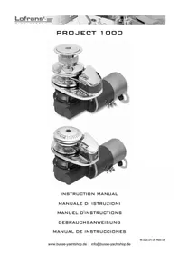
Brand : Lofrans
Model : Project X2
Category : Electric winch