Original 6 - Bike Woom - Free user manual and instructions
Find the device manual for free Original 6 Woom in PDF.


User questions about Original 6 Woom
0 question about this device. Answer the ones you know or ask your own.
Ask a new question about this device
Download the instructions for your Bike in PDF format for free! Find your manual Original 6 - Woom and take your electronic device back in hand. On this page are published all the documents necessary for the use of your device. Original 6 by Woom.
USER MANUAL Original 6 Woom
Instructions for use
04.23
natural_image
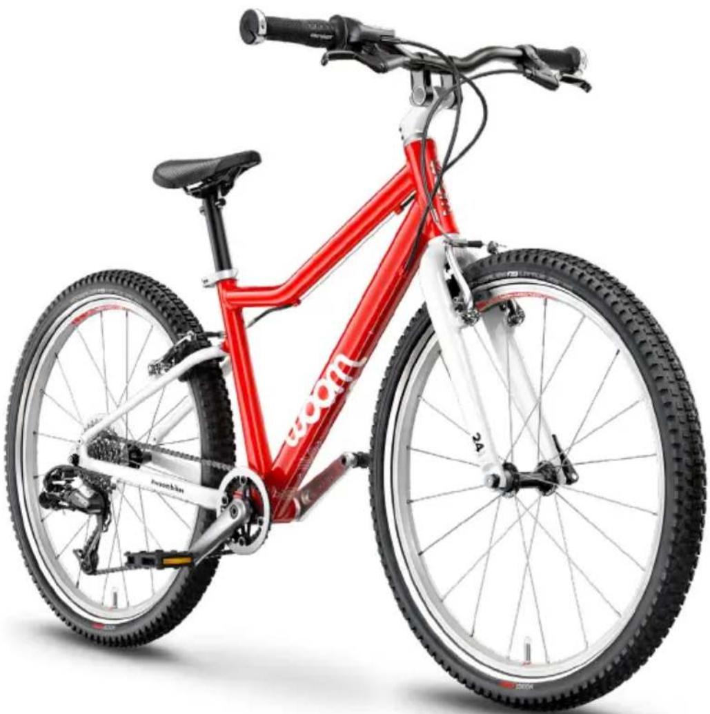
Red bicycle with visible frame and wheel, no text or symbols present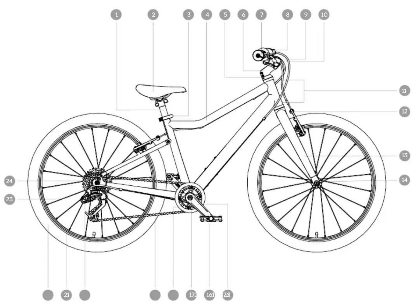
text_image
1 2 3 4 5 6 7 8 9 10 11 12 13 14 21 23 24woom ORIGINAL 4/5/6
EN Instructions for use....35
FR Mode d'emploi 69
natural_image
Line drawing of a bicycle with front wheel, rear wheel, and side-mounted components (no text or symbols)Lenker montieren
natural_image
Technical line drawing of a mechanical linkage assembly (no text or symbols)natural_image
Line drawing of a mechanical device with a lever and adjustment knob (no text or symbols)natural_image
Line drawing of a bicycle handle with a hand holding a dollar sign and a curved arrow indicating rotation (no text or symbols)natural_image
Line drawing of a bicycle handle with a circular arrow indicating rotation (no text or symbols)natural_image
Pure mechanical diagram showing a lever and connecting rod (no text or symbols)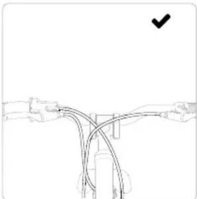
natural_image
Pure diagram of a road intersection with no text, numbers, or symbols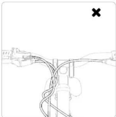
natural_image
Diagram of a bridge with cables and a marked cross symbol (no text or labels)
WARNUNG
natural_image
Simple line drawing of a hand holding a tool with a trash bin, no text or symbols presentnatural_image
Line drawing of a bicycle wheel with visible spokes and hub (no text or symbols)natural_image
Technical line drawing of a mechanical component with no visible text or symbolsnatural_image
Diagram of a bicycle wheel with a hand and lock mechanism, no text or symbols presentnatural_image
Diagram of bicycle wheel assembly with directional arrows indicating motion (no text or symbols)natural_image
Line drawing of a mechanical component with a curved handle and arrow indicating rotation (no text or symbols)natural_image
Line drawing of a bicycle suspension system with a lever and wheel (no text or symbols)natural_image
Line drawing of a bicycle seatbelt buckle with no text or symbolsnatural_image
Mechanical diagram showing a bicycle wheel and mechanical linkage with an arrow indicating rotational motion (no text or symbols)natural_image
Mechanical linkage diagram showing a lever mechanism with a rotational arrow (no text or symbols)natural_image
Technical illustration showing two mechanical assembly steps with rotating components (no text or symbols)natural_image
Line drawing of a bicycle with front wheel, rear wheel, and suspension components (no text or labels)natural_image
Silhouette of a person riding a bicycle against a solid yellow background (no text or symbols)text_image
Technical diagram of a manual tool with numbered annotations indicating key componentsnatural_image
Line drawing of a mechanical clamp or tool with a handle and spring, no text or symbols presentnatural_image
Line drawing of a robotic arm with a directional arrow indicating movement (no text or symbols)natural_image
Line drawing of a bicycle suspension system with rope and pulley (no text or symbols)natural_image
Simple line drawing of a mechanical component with a checkmark mark (no text or symbols)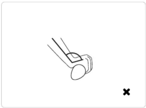
natural_image
Simple line drawing of a mechanical component with a cross mark, no text or symbols presenttext_image
Technical diagram showing a mechanical component with labeled parts 1 and 2, indicating directional movement or assembly.9 Reinigung
text_image
Technical diagram showing mechanical assembly with labeled parts 1 and H, including a magnified inset of the component.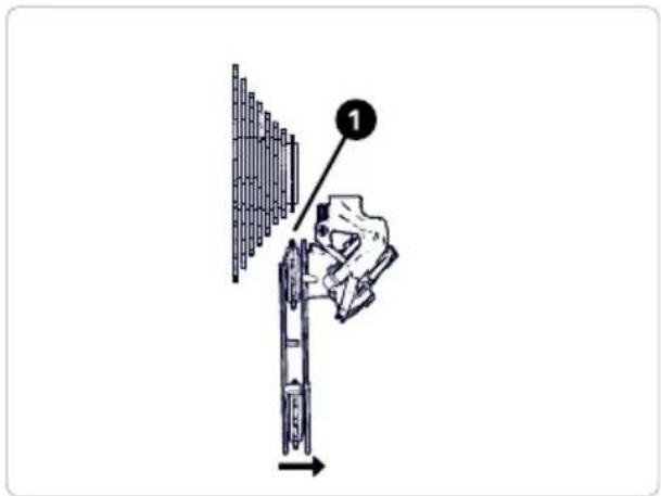
text_image
Diagram showing a hand using a tool to adjust or install a mechanical component, with labeled step 1 pointing to the component.Drehschaltgriff
natural_image
Line drawing of a cable connector with labeled component (no text or symbols present)10 5 Bremsen

WARNUNG
text_image
WEAR LINEBremsen einstellen
natural_image
Technical line drawing of a mechanical assembly with no visible text or symbols
natural_image
Line drawing of a mechanical component with no visible text or symbols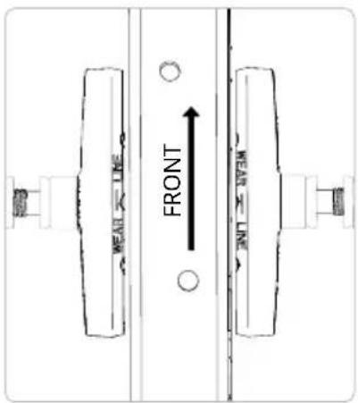
text_image
FRONT HEAD LINE TOP 300natural_image
Technical line drawing of a mechanical assembly with no visible text or symbolsnatural_image
Technical line drawing of a mechanical clamp or bracket assembly (no text or symbols)natural_image
Line drawing of a bicycle steering wheel with a handle and valve (no text or symbols)natural_image
Line drawing of a bicycle steering wheel with a labeled component (no text or symbols present)natural_image
Technical line drawing of a bicycle suspension bracket with no visible text or symbolsnatural_image
Technical line drawing of a mechanical clamp or bracket assembly with directional arrows indicating movement (no text or symbols present)natural_image
Technical line drawing of a mechanical clamp or bracket assembly (no text or symbols)1 Important notes on this document
1.1 Meaning of the symbols....37
1.2 Tips, notes and advice....38
2 Important notes on your woom bike
2.1 What your woom bike was built for 40
2.2 What your woom bike was not built for 40
2.3 Liability waiver 40
3 Important safety information
4 The components on your woom bike
5 Functions of the key components
5.1 Stability – the frame....45
5.2 Front wheel mount and shock absorption – the fork....45
5.3 Steering – the handlebars....45
5.4 Shock absorption and grip – the tyres....45
5.5 Stopping in time – the brakes....45
5.6 Drive – the chain and the gears 45
6 Preparing your woom bike for the first ride
6.1 Unpacking 46
6.2 Assembly 47
7 Adjusting the woom bike to your child
7.1 Adjusting the saddle height....52
7.2 Setting the position of the brake lever and reach....53
7.3 Adjusting the position of the handlebars 54
7.4 Properly adjusting the woom Ergogrips 55
8 How to ride
8.1 How to brake....56
8.2 Shifting correctly....56
9 Cleaning
9.1 Frame, handlebars, fork, wheels 57
9.2 Chain, cassette, front chainring....57
9.3 Brakes....57
10 Maintenance
10.1 Tyres 58
10.2 Chain....59
10.3 Handlebars, headset and fork....59
10.4 Gearing....59
10.5 Brakes....61
10.6 Cranks and bottom bracket....65
10.7 Spokes and wheels....65
11 Maintenance schedule
12 Tightening torques
13 For the good of the environment
13.1 Disposal of packaging....68
13.2 Disposal of your old bike....68
14 Warranty
WARNING
This manual contains information on how to safely operate the bike. Please read these instructions carefully prior to the first use and keep them in a safe place. This manual meets the requirements of 16 CFR 1512.
© 2023 woom GmbH
This manual is protected by copyright.
All rights reserved.
This version replaces all other versions.
The original of this manual was written in German.
Duplication, translation or transfer to an electronic medium or another machine-readable form in full or in part is prohibited.
This manual was created to the best of the author's knowledge. Nevertheless, woom GmbH assumes no liability for the completeness or correctness of the information.
1 Important notes on this document

WARNING
Failing to observe the points listed in this chapter and its subchapters can result in material damage, severe health damage (risk to life) or death.
Your woom bike is delivered in a partially assembled state. Prior to the first ride, a number of adjustments are necessary to put the woom bike in a ridable condition. For more information, please see the assembly instructions in Chapter 6.
Cycling is a fun and healthy activity when carried out responsibly. This operator's manual will help you to ensure that your child uses the woom bike safely and in line with its intended use. To that end, please read this operator's manual in its entirety and pay special attention to all the warnings and maintenance notes before your child uses the woom bike for the first time.
If the woom bike is lent to someone or if other people are supervising your children, ensure that all of the users and people providing supervision have also studied the operator's manual.
1 1 Meaning of the symbols
In this manual, the following symbols are used:

WARNING
Failure to observe this information can result in material damage, severe damage to health (danger to life) or death.

CAUTION
Failure to observe this information can result in malfunction, material damage, dangerous situations and injury.
TIP
Indicates useful tips.
1 2 Tips, notes and advice
As the parent or person supervising, you are responsible for the actions and safety of your child. If you allow your child to ride a bike, you assume responsibility for the associated hazards and risks. Both you and your child must understand and follow the rules for safe and responsible bike riding and use the bike for its intended purpose, as well as endeavouring to carry out the necessary maintenance. We want to help you to teach your child to ride a bike correctly right from the beginning and direct your attention to the following warnings:
Helmet and clothing
Equip your child with an approved helmet that fits correctly and make sure they always wear it while riding the bike. Make sure your child is appropriately attired with bright (ideally reflective), close-fitting clothing so that others can see your child in plenty of time. Sturdy shoes with a firm, grippy sole and suitable protective wear are highly recommended.
Safe and responsible use
Explain to your child in an understandable way how the brakes work and make sure that they are familiarised with the brakes before their first ride. Teach your child how to use the woom bike safely and responsibly in the environment in which they will be riding it.
National regulations and private forest roads
Find out about applicable national regulations and follow traffic signals and signage. In addition, observe the general rules of safe and responsible bike riding. Please also be aware that different regulations apply on forest roads and hiking trails than on public roads.
Accurate assessment of abilities
You know your child's abilities and degree of coordination best. Pay attention to what your child can handle confidently to ensure that they are always safe.
2 Important notes on your woom bike

WARNING
Improper use of your woom bike other than for its intended purpose can lead to material failure, falls and serious injury. To avoid these consequences, observe the notes listed under 2.1 and 2.2.
Care for and maintain the woom bike regularly and follow the maintenance schedule recommended in Chapter 11.

CAUTION
When replacing parts, use only compatible original spare parts and observe the notes in the manufacturer's manual. Failure to observe this information can result in malfunction, material damage, dangerous situations and injury. For additional information on compatible replacement parts, contact our customer service via the woom website (https://woom.com) or your dealer. Parts susceptible to wear and tear in the drive train (chainring, cassette) may only be replaced with original spare parts.
To avoid damage due to overloading your woom bike, do not exceed the maximum weight of rider and load or the maximum gross weight (rider, load and bike) under any circumstances (see table).
| Bike model Bike weight [kg] | (without pedals) | Maximum weight [kg] |
| rider + load |
woom ORIGINAL 4/5/6 7.3/8.2/9.1 <40/71/80
| Bike model Maximum weight [kg] | Maximum weight [kg] |
| rider + load | rider + load + bike |
woom ORIGINAL 4/5/6 62/71/80 70/80/90
woom bikes USA
To ensure the safe use of your woom bike and avoid injury during use, measure your child's inseam prior to the first ride. Compare the result with the minimum inseam measurements in the table below. The measured inseam length must be equal to or above the value listed for your bike model in the table.
Bike model Minimum inseam [cm]
woom ORIGINAL 4/5/6 52/64/69
TIP
To measure the inseam, have your child stand up straight with their back to the wall. Take a hardback book (or a similar item) and place the spine of the book, facing upward, at your child's crotch with the same slight pressure applied by a bike saddle while riding. Now measure the distance between the floor and the edge of the book's spine as vertically as possible. The measurement is your child's inseam.
2 1 What your woom bike was built for
woom ORIGINAL
The woom ORIGINAL is a children's bike developed specially for riding in urban settings, on light off-road terrain and in nature. Depending on the size of the bike, the woom ORIGINAL is designed for children measuring between 95 and 165 cm in height (roughly ages 3 to 14 years). The woom ORIGINAL in sizes 3–6 is approved for use with a rack (max. load 18 kg).

CAUTION
Intended use also means following the operation, maintenance and repair recommendations contained in this operator's manual. Failure to observe this information can result in malfunction, material damage, dangerous situations and injury.
2 2 What your woom bike was not built for
woom ORIGINAL
√ The woom ORIGINAL is not designed for jumps higher than 15 cm, stunts or extreme sports.
√ The frames and other components on the woom ORIGINAL are not designed for use by adults.
√ The woom ORIGINAL is not designed for use by more than one person, even if the maximum weight allowed is not exceeded.
√ The woom ORIGINAL is not designed to have a child carrier mounted on it.
√The woom ORIGINAL is not suitable for use with bike trailers.
2 3 Liability waiver
The information, data and notes provided in this manual were current as of the time of printing. The illustrations are symbolic graphics and do not necessarily correspond to reality. The information, illustrations and descriptions contained in this manual may not be used as a basis for claiming the right to exchange products which have already been delivered. We reserve the right to make technical changes. Changes, errors and typos may not be used as
grounds for claiming damages. The information in this manual describes the characteristics of the product but does not make any assurances in this regard. We accept no liability for damage or injuries arising from:
√Disregarding the assembly and operating instructions
√Unauthorised modifications to the product
√Incorrect operation
√Neglectful maintenance
√ Misuse – use of the product not in conformity with the intended use
3 Important safety information

WARNING
Failing to observe the warnings listed in this chapter can result in material damage, severe damage to health (danger to life) or death.

CAUTION
Choking hazard due to small parts. Not for children under 3 years. Keep loose parts and plastic bags out of the reach of children. Failure to observe these guidelines may result in a choking hazard.
√ Make sure your child always wears clothing appropriate for cycling. They should always wear a certified bicycle helmet. Protective equipment and suitable robust footwear should be worn when riding the woom bike.
√ Do not tow or push the woom bike.
√Have damage or defects repaired immediately by a professional.
√Your child should not carry passengers on a woom bike.
√ Adult assembly required.
√ Your child must be mentally and physically able to operate the bicycle safely. As with any sport, bike riding entails the risk of personal injury and material damage. Operation according to intended use and proper maintenance reduce the risk of injury.
√ Do not modify your woom bike.
√ Use only woom-approved parts. Do not add a motor to the woom bike.
√Risk of injury due to pointed and hard metal objects.
√The woom bike is made of metal. Falls may result in injury.
√ Parts made of composites can be damaged by high temperatures. Exposure to high temperatures (above 80^ C) should therefore be avoided for parts made of composite material.
√Risk of injury due to damaged and protruding parts!
Check your woom bike and its components for damage after falls.
√Risk of injury from falls!
The saddle, handlebars and pedals have to be adjusted properly and tightened adequately.
Only the saddle should be used for sitting.
Avoid steep slopes or steps.
While riding, your child should always be aware of the surroundings and the surface. Your child should take special care when riding in wet weather. Your child should avoid riding on surfaces slippery with rain or ice. If this is unavoidable, they should go very slowly and with caution to ensure safe stopping at all times.
√ If your child wants to use the woom bike on public roadways, find out about the applicable national regulations and equip the woom bike with the required accessories. Failure to obey the rules of the road may result in injury to your child or others.
√ The woom bike may only be operated when in good working order. woom GmbH assumes no responsibility for injuries due to damaged or worn parts (e.g. brakes).
√Risk of injury due to rotating parts!
Rotating parts, such as wheels, increase the risk of injury. Make sure to maintain a safe distance from rotating parts when using or maintaining the woom bike.
√ Use bike lights at night or when visibility is poor (not included with bike).
√ Reflectors must be clean, straight, unobscured and securely mounted. Damaged or missing reflectors must be replaced.
√ The only way to ensure reliable and safe use of the woom bike is if it is built and assembled in line with the instructions provided by woom GmbH. For this purpose follow this manual, in particular the assembly instructions in Chapter 6.
√ Ensure that your woom bike is kept securely behind a locked door or locked up (with a suitable bike lock, for instance). If, despite all of your security measures, your woom bike is taken without your permission, report it immediately to the authorities (for such cases make sure you always have the frame number of your woom bike to hand).
4 The components on your woom bike
Numbering to match illustration on the inside cover
1 Seatpost
2 Saddle
3 Seatpost clamp
4 Frame
5 Headset clamp
6 Stem
7 Ergogrips
8 Twist shifter
9 Brake lever
10 Vario clamps
11 Head tube
12 Brake arms
13 Fork
14 Hubs
15 Cranks
16 Pedals
17 Bottom bracket (in frame)
18 Chainguard
19 Chain
20 Derailleur
21 Rims
22 Tyres
23 Spokes
24 Cassette
5 Functions of the key components
5 1 Stability - the frame
Each woom frame is made of lightweight, high-quality aluminium tubing. That gives it the necessary stability and keeps the weight down to a minimum.
5 2 Front wheel mount and shock absorption – the fork
The fork connects the front wheel with the frame and serves as the mount for other components, such as the stem and the front brake.
5 3 Steering - the handlebars
The position and shape of the handlebars encourage the right riding posture. The handlebars are also the mount for the grips and other components (brake levers, gear shifters, bell, reflector, etc.)
5 4 Shock absorption and grip - the tyres
The tyres have to bear the weight of the bike, the rider and any additional load. The greater the weight, the higher the tyre pressure should be. The permissible pressure range is specified on the tyre. See also Chapter 10.1.
5 5 Stopping in time – the brakes
The woom ORIGINAL has two rim brakes, one on the front wheel and one on the rear wheel. When braking, the brake pads are pressed against the braking surface of the rim, thus slowing the wheel. See also Section 10.5.
5 6 Drive - the chain and the gears
The cranks connect the pedals with the bottom bracket. The chainring attached to the right crank transfers the drive force through the chain to the rear wheel. One or more sprockets of various sizes are mounted to the rear wheel (together they are called a cassette).
This is also where the rear derailleur sits. The derailleur guides and shifts the chain onto a different sized sprocket. This changes the gear ratio.
When the chain is on a small rear sprocket, this is called a high gear ratio. Pedalling in a high gear means the bike covers more distance per pedal revolution.
When the chain is on a large rear sprocket, this is called a low gear ratio. Pedalling in a low gear means the bike covers less distance per pedal revolution.
6 Preparing your woom bike for the first ride

WARNING
The woom bike must be assembled by an adult.
Plastic bags and small parts of the bike and packaging must be kept out of the reach of children. Failure to observe this information can result in material damage, severe damage to health (danger to life) or death.
Please note: The designations "left" and "right" in these instructions always refer to the left and right sides of the bike in the direction of travel as seen from above.
Under Service & Info on the woom website (woom.com), you will find videos to help you assemble your woom bike.
6 1 Unpacking

CAUTION
When cutting the cable ties, take care not to damage parts of the bike, especially the tyres, brake cables and other cables. Failure to observe this information can result in malfunction, material damage, dangerous situations and injury.
- Remove the packaging and carefully cut any cable ties.
- Remove the protective plastic disc from the derailleur on the rear wheel.
- Note down the frame number of your woom bike. This number is unique to your bike and provides an important way of identifying it when reporting a theft to the police and liaising with your insurance provider. You can find the number on the underside of the frame near the bottom bracket.
6 2 Assembly

CAUTION
See Chapter 12 for the tightening torques when assembling. Failure to observe this information can result in malfunction, material damage, dangerous situations and injury.
WARNING
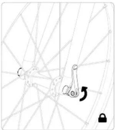
Before your child uses the woom bike, always make sure that all quick-release levers are firmly closed. When the quick-release lever is in the closed position, you will be able to see the word "CLOSE" on the outside of the lever.
When closing quick-release levers, make sure that they are completely closed and do not bump against other components in the closed position. Failure to observe this information can result in material damage, severe damage to health (danger to life) or death.
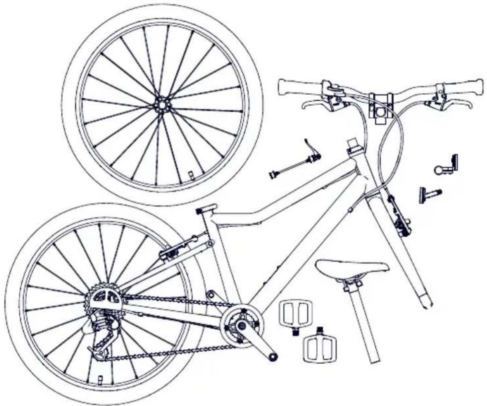
Check your woom bike against the illustration to make sure it is complete.
natural_image
Line drawing of a bicycle with front wheel, rear wheel, and side-mounted components (no text or symbols)Installing the handlebars
natural_image
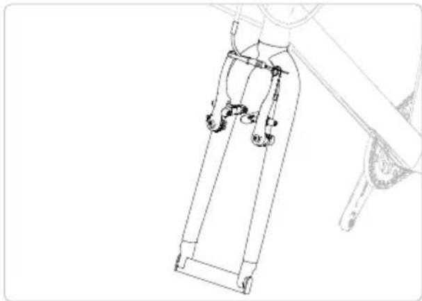
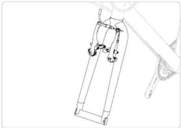
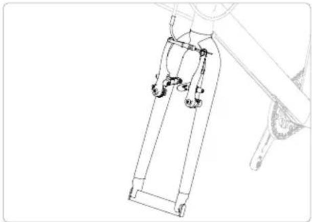
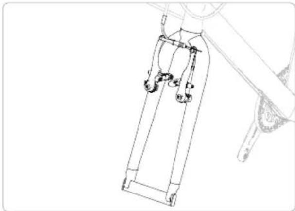
Technical line drawing of a mechanical support structure (no text or symbols)Align the fork so that the brake arms are facing forward.
natural_image
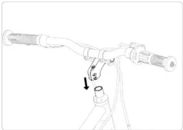
Line drawing of a mechanical device with a lever and cable, showing a downward force arrow (no text or symbols)Slide the handlebars and stem unit onto the steerer tube as far as it will go.
natural_image
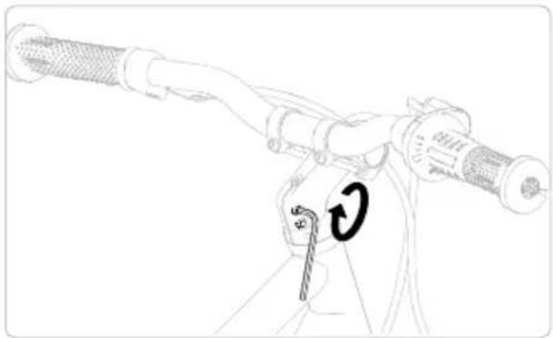
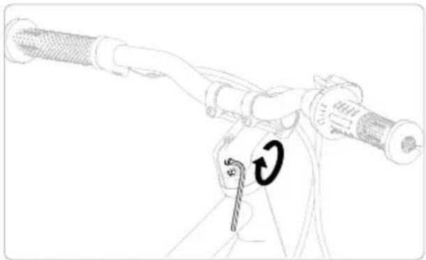
Line drawing of a bicycle steering wheel with a hand holding the steering wheel and a dollar sign indicating price (no text or symbols present)Align the handlebars and tighten both clamp bolts alternately several times until the required torque is reached.
natural_image
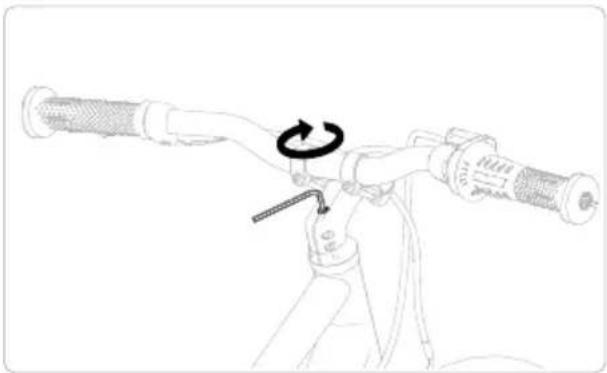
Line drawing of a bicycle steering wheel with a wrench and circular motion indicator (no text or symbols)After tightening the clamp bolts, tighten the locking bolt on the top of the stem to the required torque.
natural_image
Pure mechanical diagram showing a lever mechanism with no text or symbols
natural_image
Pure electrical circuit lines without any symbols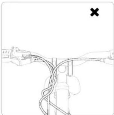
natural_image
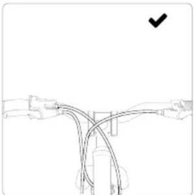
Diagram of a cable or cable connection with a cross mark, no text or symbols presentWARNING
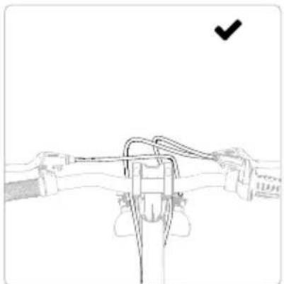
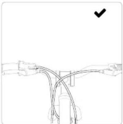
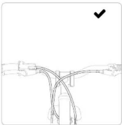
The shifting cable must run to the right and the rear brake cable must run to the left of the head tube. Failure to observe this information can result in material damage, severe damage to health (danger to life) or death.
Installing the front wheel
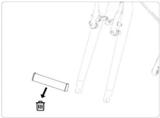
natural_image
Simple line drawing of a hand holding a tool with a trash bin, no text or symbols presentRemove the transport protectors from the fork ends and front wheel.

natural_image
Line drawing of a bicycle wheel with visible spokes and frame structure (no text or symbols)Insert the front wheel into the fork. Note the marking on the tyre for the correct direction of rotation.
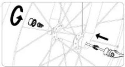
text_image
G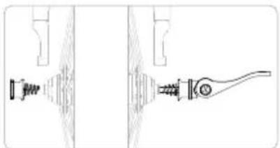
natural_image
Technical line drawing of a mechanical component with no visible text or symbolsPass the quick-release through the hub and tighten the nut slightly.
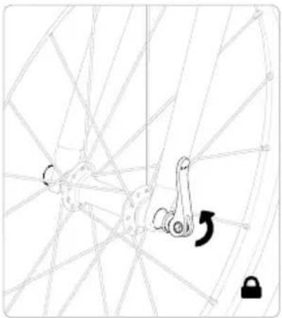
natural_image
Diagram of a bicycle wheel with a key inserted into the seat, showing no text or symbolsClose the quick-release lever completely to lock the wheel in place. If the quick-release lever is difficult to close, open it and loosen the nut slightly.
natural_image
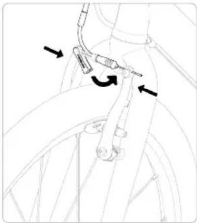
Diagram of bicycle wheel assembly with directional arrows indicating motion (no text or symbols)Press the brake arms together and insert the brake cable.
Installing the saddle
natural_image
Line drawing of a car interior showing a hand holding a steering wheel (no text or symbols)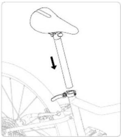
natural_image
Line drawing of a bicycle suspension mechanism with a downward arrow indicating motion (no text or symbols)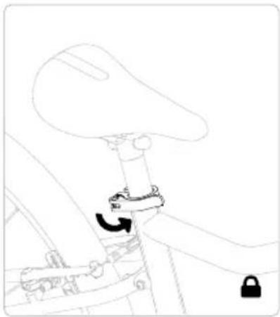
natural_image
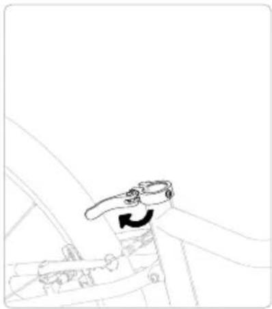
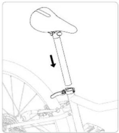
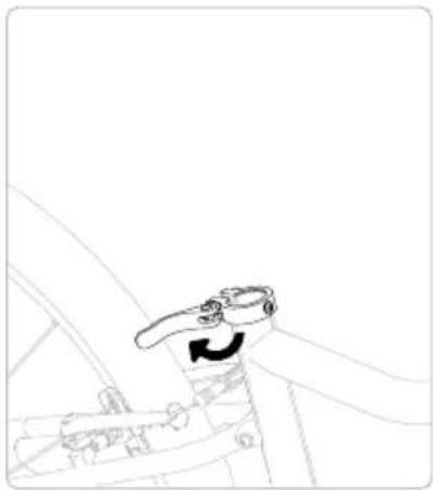
Line drawing of a bicycle seatbelt mechanism with no text or symbolsOpen the quick-release lever. Insert the seatpost into the frame and position it at the desired height (see Chapter 7 for instructions for saddle height adjustment).
Close the quick-release lever completely.
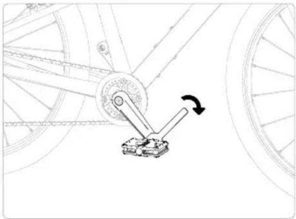
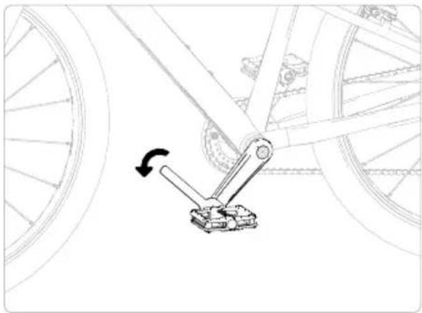
Installing the pedals
natural_image
Technical line drawing of a bicycle wheel assembly with a lever mechanism (no text or symbols)Screw the pedal marked "R" into the right crank arm in the direction of the arrow and tighten it with the open-ended spanner.
natural_image
Mechanical linkage mechanism diagram showing a lever and wheel assembly (no text or symbols)Screw the pedal marked "L" into the left crank arm in the direction of the arrow and tighten it with the open-ended spanner.
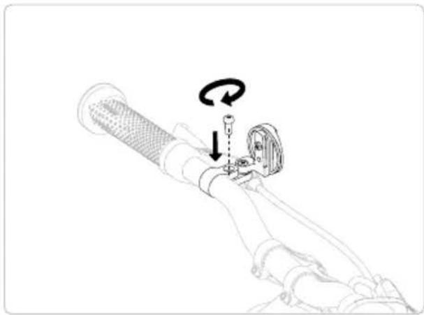
Installing the reflectors
natural_image
Line drawing of a robotic arm with a tool and rotating motion indicator (no text or symbols)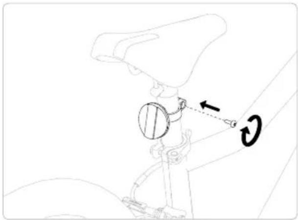
natural_image
Technical line drawing of a mechanical linkage with a circular component and directional arrows (no text or symbols)Mount the white reflector on the handlebars and the red reflector on the seatpost.
7 Adjusting the woom bike to your child

WARNING
Adjustments to the woom bike must be carried out by an adult. Failure to observe this information can result in material damage, severe damage to health (danger to life) or death.

CAUTION
See Chapter 12 for the tightening torques when making adjustments. Failure to observe this information can result in malfunction, material damage, dangerous situations and injury.
When you have assembled all of the parts, the woom bike is ready to ride. You will need to adjust the height of the saddle in order to find the optimal riding position for your child.
The position of the brake levers and/or shifter and the angle of the handlebars can also be adjusted to fit your child.
7 1 Adjusting the saddle height
To loosen and tighten the seatpost clamp, follow the assembly instructions for your woom bike in Chapter 6.2 and the specified tightening torques in Chapter 12.
WARNING
Observe the minimum insertion depth of the seatpost! See the “min” mark on the seatpost. When adjusting the saddle, do not go below the minimum saddle height (see table in this chapter, 7.1). Failure to observe this information can result in material damage, severe damage to health (danger to life) or death.
natural_image
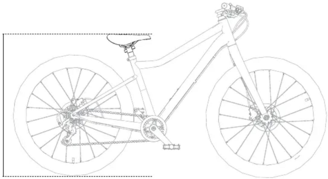
Line drawing of a bicycle with front wheel, rear wheel, and suspension components (no text or labels)Saddle height measurement – see the table for the minimum saddle height.
Bike model Minimum saddle height [mm]
woom ORIGINAL 4/5/6 560/670/750

CAUTION
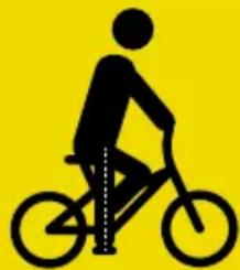
Correct seat height: Sitting on the saddle, place the heel on the pedal in the lowest position – the leg should be fully extended. When sitting on the saddle, the child should always be able to touch the ground with both feet and have a stable stance once the saddle height has been adjusted. For beginners, set the saddle lower.
natural_image
Silhouette of a person riding a bicycle against a solid yellow background (no text or symbols)7 2 Setting the position of the brake lever and reach
The woom bike is delivered with a suitable standard distance based on the model.
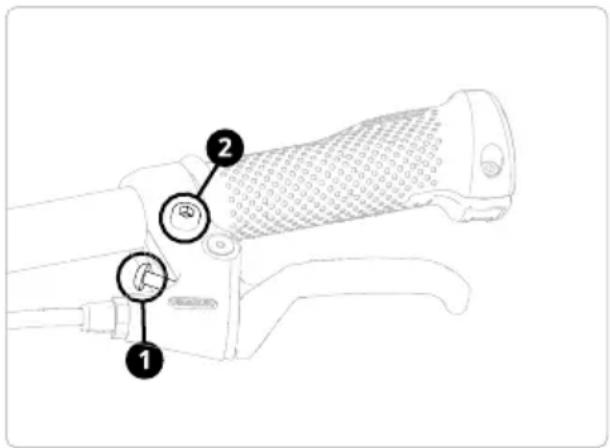
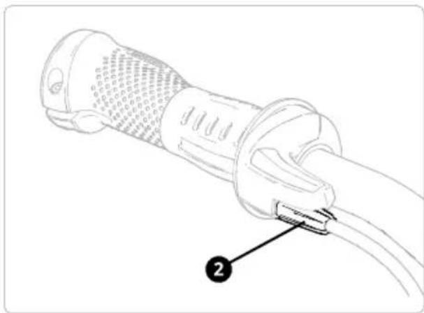
To reduce the distance between the brake lever and the handlebar grip, turn the brake lever barrel adjuster (1 - see illustration) clockwise. To increase the distance, turn the barrel adjuster anti-clockwise (observe warning!).
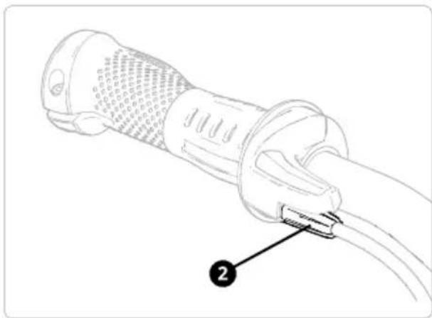
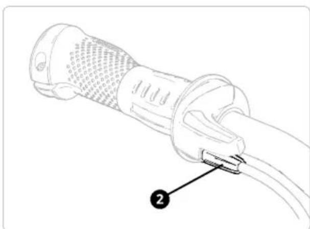
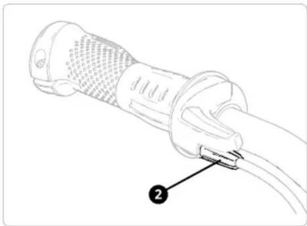
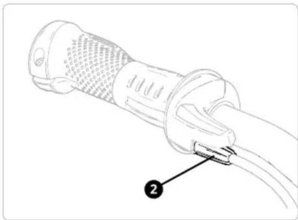
To adjust the position of the brake lever on the handlebars, loosen the clamp bolt (2 - see illustration) by turning it anti-clockwise and reposition the lever.
Finally, tighten the clamp bolt to the recommended torque. Make sure that the brake levers are positioned so that your child can brake safely without undue effort and that the brake lever is easy to reach.
text_image
Technical diagram of a manual tool with numbered annotations indicating key componentsAdjustment bolts for woom ORIGINAL 4, woom ORIGINAL 5 and woom ORIGINAL 6

WARNING
The brake lever must not touch the handlebar grip, even when squeezed hard. Turn the adjustment bolt just far enough to ensure that the brake lever can never touch the handlebar grip, even when applied under serious force. Never completely unscrew the adjustment bolt from the brake lever. Failure to observe this information can result in material damage, severe damage to health (danger to life) or death.
7 3 Adjusting the position of the handlebars
WARNING
Make sure that the handlebars are centred after all adjustments. The marking on the front (if present) helps with alignment.
Also make sure that the clamps are not twisted and are parallel to each other. Ensure that the handlebars cannot be rotated when the bolts are tightened. See Chapter 6 for more information on properly installing the handlebars on your woom bike. Failure to observe this information can result in material damage, severe damage to health (danger to life) or death.
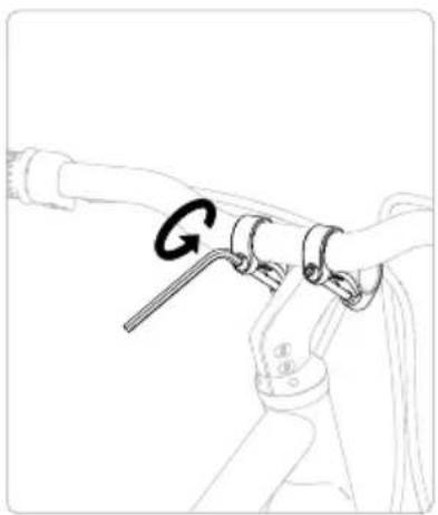
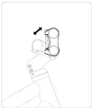
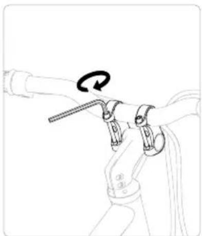
You can adjust the position and angle of the handlebars to your child's size with the stem or Vario clamps. Your child should be able to reach the grips easily while sitting on the saddle, leaning forward a bit with slightly bent arms. To make the adjustment, loosen the bolts of the stem or Vario clamps. Move the handlebars into the desired position. Make sure that the grips and brake levers are back in the correct position and tighten the bolts to the recommended torque.
Stem with Vario clamp
natural_image
Line drawing of a mechanical clamp or tool with a handle and spring, no text or symbols presentLoosen the bolts on the Vario clamp a bit.
natural_image
Line drawing of a robotic arm with a directional arrow indicating motion (no text or symbols)Adjust the angle of the handlebars.
natural_image
Line drawing of a mechanical device with a rotating lever and rope (no text or symbols)Tighten both bolts on the Vario clamp alternately several times until the required torque is reached.
7 4 Properly adjusting the woom Ergogrips

WARNING
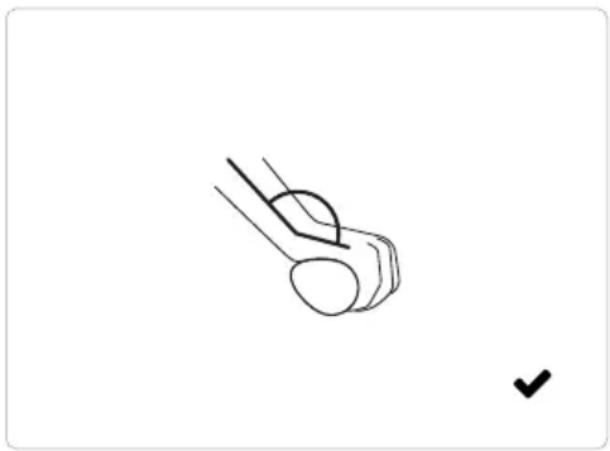
Before making any adjustments and tightening the clamp bolts, make sure that the Ergogrips are pushed inwards onto the handlebars as far as they will go. Failure to observe this information can result in material damage, severe damage to health (danger to life) or death.
natural_image
Simple line drawing of a mechanical component with a checkmark mark (no text or symbols)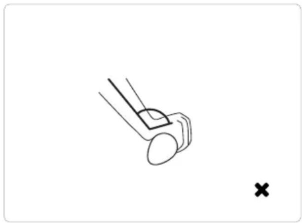
natural_image
Simple line drawing of a mechanical component with a cross mark, no text or symbols presentThe woom Ergogrips are designed to support the heel of your child's hand. When your child is holding the grips in a normal riding position, the wrists should be slightly bent. To adjust, loosen the clamp bolt of the Ergogrip. Rotate the grips to the desired position and tighten the clamp bolt to the recommended torque.
8 How to ride
8 1 How to brake
√The left brake lever operates the front brake.
√The right brake lever operates the rear brake.
To get the most out of the brakes, please note the following points:
√Your child should always apply both brakes at the same time.
√The optimal use of the brakes depends on the road surface.

CAUTION
Depending on the road surface and conditions, the braking distance may vary. On wet roads in particular, make sure that your child makes allowance for a longer braking distance. Failure to observe this information can result in malfunction, material damage, dangerous situations and injury.
8 2 Shifting correctly
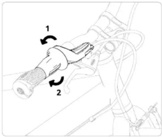
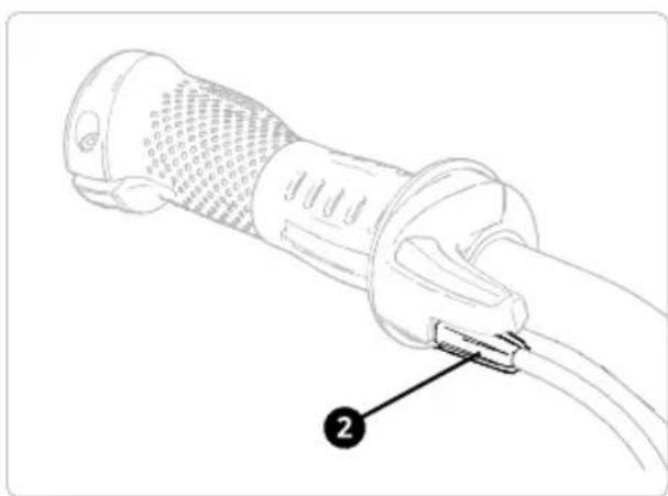
√ By rotating the twist shifter (1) backwards, your child will shift to a lower gear (for climbs, headwinds or more resistance).
√ Your child can shift to a higher gear (for flat sections and downhills primarily) by rotating the twist shifter (2) forwards. One click will change one gear.
text_image
Diagram of a mechanical device with labeled parts and directional arrows indicating motion or assembly.9 Cleaning
Clean the woom bike regularly to prevent damage and keep your child safe on the road.

CAUTION
Do not use a high-pressure washer as this may damage bearings and similar components. Never clean the bicycle with acids, cleaning agents containing oil or liquids containing solvents. Failure to observe this information can result in malfunction, material damage, dangerous situations and injury.
9 1 Frame, handlebars, fork, wheels
Clean these components with warm water, mild detergent and a soft cloth or sponge.
9 2 Chain, cassette, front chainring
Clean these components with an oily cloth or with a brush and a cleaning agent suitable for chains. After cleaning the chain, it should be oiled with a suitable lubricant (see Chapter 10.2).
9 3 Brakes
If the brakes are very dirty, you can clean them with warm water and detergent. Never use cleaning agents that contain oil.
10 Maintenance

WARNING
Periodically check the components of your woom bike for damage such as cracks and deformation to prevent component failure. If the woom bike shows signs of damage, it must not be used under any circumstances.
Before each ride, check the proper function of each component, such as brakes, wheels, drive and steering, to ensure a safe ride for your child. Damaged or non-functioning components must be replaced or serviced by a specialist. Failure to observe this information can result in material damage, severe damage to health (danger to life) or death.

CAUTION
To ensure proper functioning of your woom bike, follow the maintenance recommendations for the individual components in this chapter and the recommended actions in the maintenance schedule for periodic inspection (see Chapter 11). Failure to observe this information can result in malfunction, material damage, dangerous situations and injury.
In the Service and Info section on the woom website (woom.com), you will find helpful videos on maintaining and caring for your woom bike.
Repairs and maintenance work of any kind require expertise, experience and special tools. In order to help minimise the chances of an accident or injury, it is critical that any repairs, adjustments or maintenance work are performed by a specialist for safety reasons.
10 1 Tyres
√ Regularly check the tread and condition of the tyres.
√Replace worn or damaged tyres immediately!
√ The permissible pressure range is indicated on the tyre sidewalls and the pressure must not be above or below this range.
√ Use a pressure gauge to set the correct tyre pressure.
√ Checking the pressure by squeezing the tyres is not very reliable.

CAUTION
Insufficient tyre pressure can result in a sudden loss of pressure due to damage to the tyre, tube and rim. Check the air pressure before each ride. Failure to observe this information can result in faulty function, material damage, dangerous situations and injury.

TIP
A pressure loss of about 1 bar per month is considered normal. If a tyre loses significantly more air, the tube is defective and must be repaired or replaced.
10 2 Chain
As the chain wears, it becomes longer. If it wears too much, it can damage the sprockets. The chain and sprockets should therefore be checked regularly for wear (see Chapter 11).
Lubricating the chain
The chain must be cleaned and lubricated regularly. See Chapter 10 for information on cleaning the chain and other drive components. Use a suitable chain oil to lubricate the chain and be careful not to apply too much oil to the chain. Remove any excess oil with a rag.

WARNING
Make sure that the oil does not come into contact with the brake pads! If oil gets on the brake pads, they must be replaced. Failure to observe this information can result in material damage, severe damage to health (danger to life) or death.
10 3 Handlebars, headset and fork
The headset, located in the head tube, connects the fork to the frame and enables the handlebars to turn easily. During riding, it is subjected to heavy loads and must therefore be properly positioned. The woom bike must be inspected by a specialist if the headset or the handlebars
√wobble or have play,
√ can no longer be turned easily or are difficult to move.
10 4 Gearing
Over time, the gears can become misaligned. For this reason, they may have to be readjusted after a certain period.
If an accident or another event causes problems with the gears, they must be repaired or readjusted by a specialist.
Lower stop: Shift to the smallest sprocket and turn the adjustment screw (H) to adjust the stop so that the jockey wheel (1) sits in line with the smallest sprocket.
Upper stop: Shift to the largest sprocket and turn the adjustment screw (L) to adjust the stop so that the jockey wheel (1) sits in line with the largest sprocket.
√ Turning the adjustment screw (H) clockwise OR the adjustment screw (L) anti-clockwise will move the jockey wheel (1) towards the wheel.
√ Turning the adjustment screw (H) anti-clockwise OR the adjustment screw (L) clockwise will move the jockey wheel (1) away from the wheel.
Shifting increments:
Shift through all gears starting with the smallest sprocket. If the chain does not move to the next largest sprocket after each shift, increase the shift cable tension by turning the adjustment bolt (2) on the shifter anti-clockwise. If the chain skips several sprockets during a single shift, reduce the shift cable tension by turning the adjustment bolt (2) on the shifter clockwise.
text_image
Technical diagram showing mechanical assembly with labeled parts 1 and H, including a magnified inset of the component.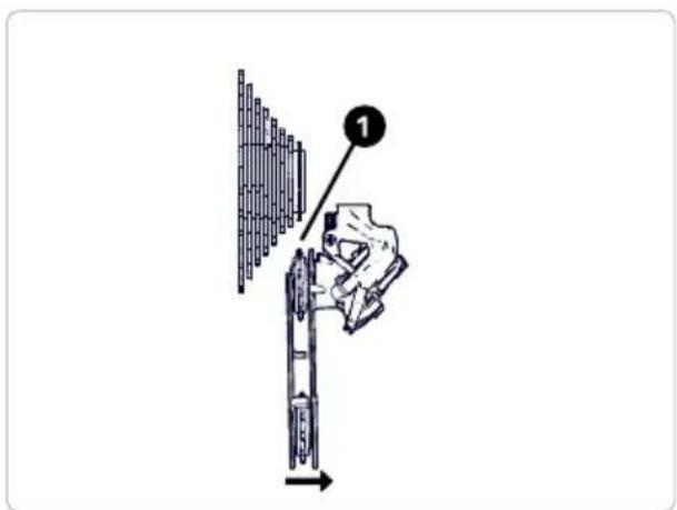
text_image
Diagram showing a hand using a tool to adjust or install a cylindrical component, with labeled step 1 and directional arrow.Twist shifter
natural_image
Line drawing of a cable connector with labeled component (no text or symbols present)10 5 Brakes

WARNING
Have repairs and adjustments to brakes carried out by trained professionals only. Brake pads must not come into contact with oil or grease. Be careful not to touch hot surfaces. Failure to observe this information can result in material damage, severe damage to health (danger to life) or death.
The braking surface and brake pads are both susceptible to wear and tear, so they need to be inspected at regular intervals (see Chapter 11). The brakes must be checked or serviced by a specialist in any case if:
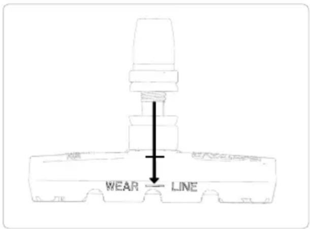
√the brake pads are worn to the indicator (WEAR LINE).
√the brake lever touches the handlebars when braking.
√the brakes screech or vibrate.
√the braking power decreases.
Wear indicator
text_image
WEAR LINEAdjusting the brakes
If the brake pads scrape against the braking surface of the rim, the brake lever can be pulled all the way back to the handlebar grip or the braking effect is too low, the brakes on the woom ORIGINAL can be adjusted according to the instructions in the following chapters. To adjust the brake lever position and the brake lever reach, see Chapter 7.
WARNING
The brake levers must be adjusted so that your child can reach them and brake safely. After every adjustment, check the brakes for proper function and braking efficiency. Check that the wheels rotate freely without resistance by lifting the front and back wheel off the ground. The brake pads and other parts of the brakes must not rub against the tyre or the braking surface.
The brake lever must never return fully to the handlebar grips when the brake is applied. The braking effect must be sufficiently high to allow safe stopping at all times. Failure to observe this information can result in material damage, severe damage to health (danger to life) or death.
Adjusting the position of the brake pads
natural_image
Technical line drawing of a mechanical assembly with no visible text or symbols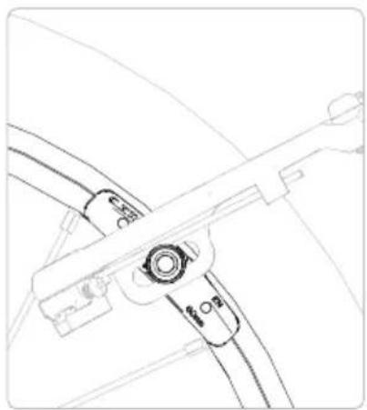
natural_image
Line drawing of a mechanical component with no visible text or symbols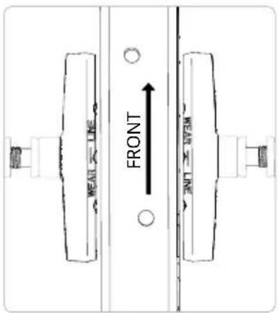
text_image
FRONT HEAD LINE TOP TOP TOPTo adjust the brake pad position, loosen the retaining bolt of the left or right brake pad so that the brake pad can be positioned or rotated. When adjusting, always loosen only one brake pad at a time. To replace the brake pads, undo the fixing bolt. Remove the worn brake pad, replace with a new one. Retighten up the fixing bolt.
Align the brake pads so that they rest centrally on and are parallel to the braking surface of the rim.
To check for correct positioning, pull lightly on the hand-brake lever so that the brake pads rest against the rim. The brake pads must never touch the tyre or protrude from the underside of the braking surface.
When adjusting the brake pads, also make sure that they are parallel to the rim lengthwise.
The distance between the brake pads and the rim must be uniform along the length of the brake pads.
natural_image
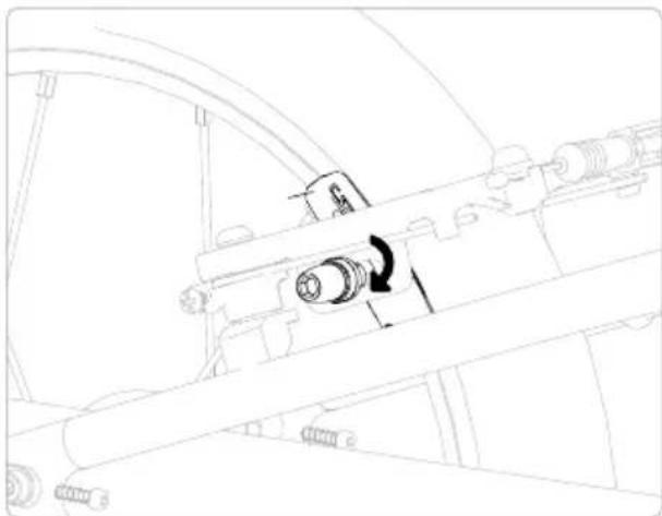
Technical line drawing of a mechanical assembly with no visible text or symbolsAfter adjusting the brake pads, tighten the brake pad retaining bolts to the required torque and check the function of the brake.
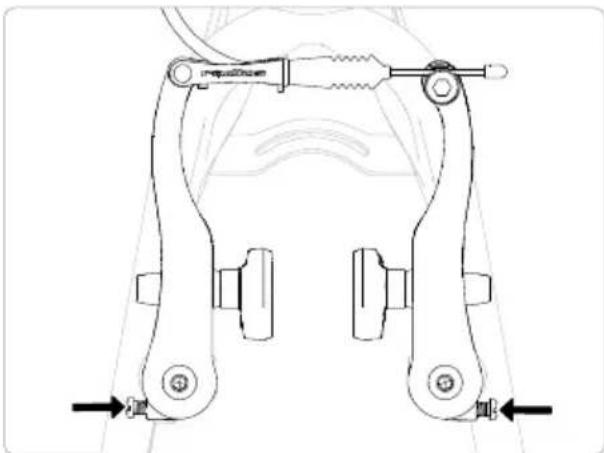
By turning the two adjustment screws, the position of the brake pads in relation to the braking surface of the rim can be adjusted. Clockwise rotation moves the brake pad away from the rim on the respective side. When turned anti-clockwise, the brake pad moves towards the rim. Turning an adjustment screw also affects the position of the brake pad on the opposite side.
natural_image
Technical line drawing of a mechanical clamp or bracket assembly (no text or symbols)Adjust the pads so that the left and right distances to the rim are equal.
The adjustment screws must never be completely unscrewed during adjustment!
Adjusting the brake cable
If the brake lever touches the handlebar grip when the brake is applied or the bite point of the brake is too close to the handlebar grip, the brake cable can be tightened by following the instructions below.
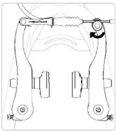
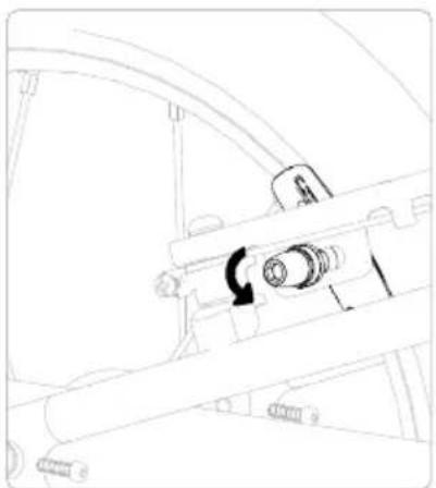
The brake cable is adjusted via the barrel adjuster on the brake levers and the clamp bolt on the brake arms. If the required brake cable adjustment cannot be made using the barrel adjuster on the brake levers, the brake cable must be readjusted using the clamp bolt on the brake arms.
Adjustment using the barrel adjuster on the brake lever
natural_image
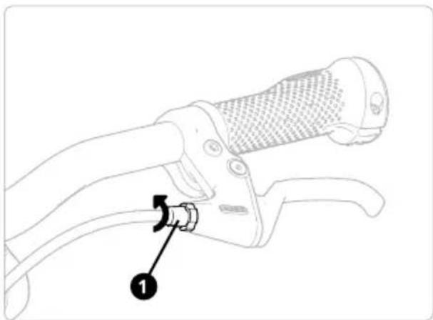
Line drawing of a bicycle steering wheel with a key inserted, showing no text or symbolsTo increase the tension of the brake cable, turn the barrel adjuster (1) anti-clockwise out of the brake lever until the desired setting is reached. To check the adjustment, squeeze the brake gently so as not to damage the thread in the brake lever. Never unscrew the barrel adjuster (1) completely and ensure that it is screwed into the brake lever by at least three turns.
natural_image
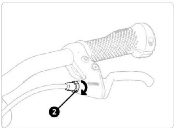
Line drawing of a bicycle steering wheel with a labeled component (no text or symbols present)After adjustment, turn the lock nut (2) clockwise until it stops on the brake lever and tighten the nut by hand. Then, check the function and braking effect of the brake.
Adjusting the brake cable with the clamp bolt on the brake arms
natural_image
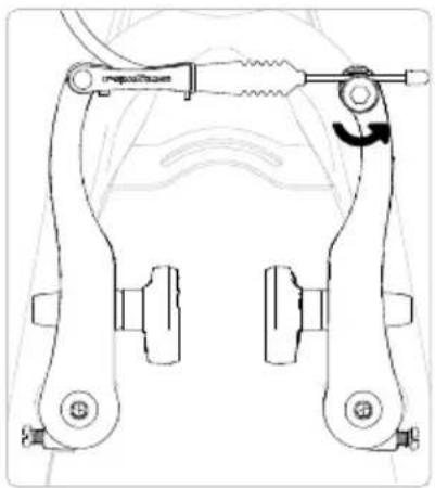
Technical line drawing of a mechanical clamp or bracket assembly (no text or symbols)To adjust the brake cable, slightly loosen the clamp bolt.
natural_image
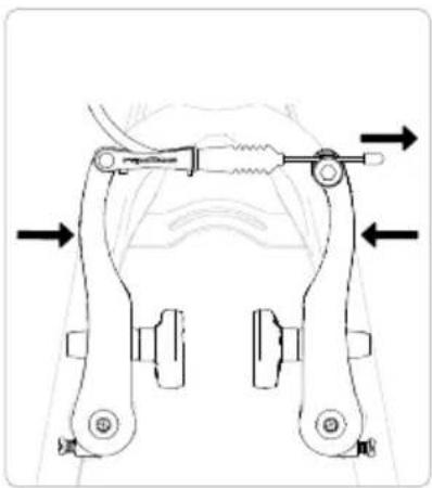
Mechanical clamp assembly diagram showing two arms with directional arrows indicating movement (no text or labels)To increase the tension on the cable, press the two brake arms together slightly by hand and pull the brake cable outwards through the clamp.

natural_image
Technical line drawing of a mechanical clamp or bracket assembly (no text or symbols)Finish up by tightening the bolt of the brake cable clamp to the required torque. Make sure that the clamp completely encloses the brake cable. After adjustment, check for proper function and braking efficiency and make sure that the brake pads are in the correct position.
10 6 Cranks and bottom bracket
Cranks can become loose. Therefore, you should check that the cranks are securely tightened at regular intervals or have them checked by a specialist.
√ Have damaged cranks repaired by professionals and replaced if necessary. Bottom brackets can wear out after a certain amount of time.
√ Have hard-to-rotate or damaged bottom brackets repaired by professionals and replaced if necessary.
10 7 Spokes and wheels
Spokes connect the hubs to the rims. They must be properly tensioned because they have an influence on how the wheel rotates. Check the spokes regularly for damage and adequate tension or have them checked by a specialist.
√ Have damaged spokes repaired by professionals and replaced if necessary.
√ If a wheel has excessive lateral or vertical runout (more than 1 mm), have it repaired or trued by a professional.
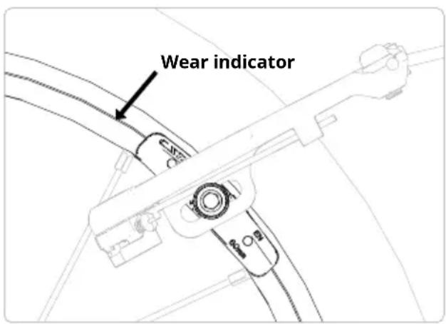
√ Regularly check the wear indicators on your bike's rims. If the linear grooves (see image) are no longer visible, the rims are worn and need replacing. Not doing so could result in equipment failure and risk of serious injury or death.
text_image
Wear indicator11 Maintenance schedule
Regular inspections of the woom bike by a professional are important for the safety of your child. When to have the woom bike serviced by a professional bike repair shop:
After riding 200 kilometres and at least once a year:
√ Have the tyres and wheels checked for soundness and proper condition.
√ Have the tightening torques checked for the handlebars, headset, cranks, pedals, saddle, seatpost and all mounting bolts.
Every 1,000 kilometres, a professional should remove, inspect, clean, lubricate and, if necessary, replace the following components:
√Hub
√Pedals
√Headset
√Brakes
√Gears
√Chain and drive components
WARNING
Be sure to have the individual components (especially frame and fork) checked regularly for damage and wear after heavy use. If your woom bike is used extensively, wear will occur more quickly and maintenance will have to be carried out earlier than the specified maintenance intervals. Failure to observe this information can result in material damage, severe damage to health (danger to life) or death.
12 Tightening torques
Tightening torques [Nm]
| Part woom ORIGINAL 4/5/6 | |
| Stem to fork | 4 |
| Stem to handlebars(Vario clamps on woom ORIGINAL 4/5/6) | 7.5 |
| Safety bolt(bearing must be adjusted so that there is no play) | 0.5-1.5 |
| Headset clamp | 4 |
| Brake lever to handlebars | 3 |
| Ergogrips to handlebars | 2 |
| Twist grip shifter to handlebars | 1.7 |
| Saddle rails (saddle to seatpost) | 4 |
| Rear wheel axle bolts | 8 |
| Brake pad retaining bolts | 6 |
| Brake cable clamp bolt | 5 |
| Rack to frame rear | 4 |
| Pedals | 20 |
13 For the good of the environment
13 1 Disposal of packaging
The packaging materials have been selected with environmental compatibility and disposal in mind and are therefore almost completely recyclable.
Recycling the packaging saves raw materials and reduces waste.
13 2 Disposal of your old bike
Old bikes often contain valuable materials. They also contain certain substances, mixtures and components that were necessary for their function and safety. If not disposed of properly, they can be harmful to human health and the environment. For this reason, do not dispose of your child's old bike with your domestic waste.
Instead, return it to your local recycling collection point or take it to a bike shop.
14 Warranty
All woom frames and components are guaranteed for 24 months from the day of purchase. This warranty does not cover normal wear and tear on components and damage resulting from crashes and incorrect use. Please keep hold of your receipt. You will need it when making a claim under the warranty. The warranty is valid worldwide. Legal warranty rights remain unaffected. Please send us a photo of the defect. We will help you quickly and with no hassle at all.
If you have bought your woom bike from one of our retailers, please contact them directly. The retailer will take care of the rest.
Find out more about the woom warranty and how to extend your warranty here: https://help.woombikes.com/article/127-guarantee-information
natural_image
Line drawing of a bicycle with front wheel, rear wheel, and side-mounted legs (no text or symbols)natural_image
Technical line drawing of a mechanical support structure (no text or symbols)natural_image
Line drawing of a mechanical device with a lever and cable, showing a downward force arrow (no text or symbols)natural_image
Line drawing of a bicycle steering wheel with a dollar sign and rotational arrow (no text or symbols)natural_image
Line drawing of a bicycle steering wheel with a hand operating the lever (no text or symbols)natural_image
Pure mechanical diagram showing a lever and connecting rod (no text or symbols)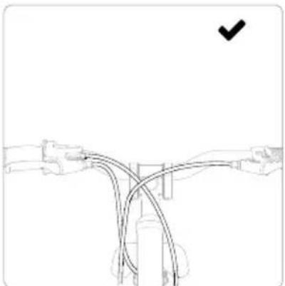
natural_image
Pure diagram of a mechanical linkage or cable system without any text, numbers, or symbols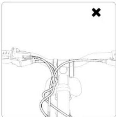
natural_image
Diagram of a mechanical linkage or cable system with no visible text or symbols
AVERTISSEMENT
natural_image
Simple line drawing of a hand holding a cylindrical object with an arrow pointing to it, next to a pair of legs (no text or symbols)natural_image
Line drawing of a bicycle wheel with spokes and wheels (no text or symbols)natural_image
Technical line drawing of a mechanical component with no visible text or symbolsnatural_image
Diagram of a bicycle wheel with a key inserted into the wheel (no text or labels)natural_image
Diagram of bicycle wheel assembly with directional arrows indicating motion (no text or symbols)natural_image
Line drawing of a car interior showing a hand holding a steering wheel (no text or symbols)natural_image
Line drawing of a bicycle support structure with a downward arrow indicating motion (no text or symbols)natural_image
Line drawing of a bicycle seatbelt mechanism with no text or symbolsnatural_image
Mechanical diagram showing a bicycle wheel and mechanical lever assembly with rotational motion indicator (no text or symbols)natural_image
Mechanical linkage diagram showing a bicycle's wheel and lever mechanism (no text or symbols)natural_image
Line drawing of a robotic arm with a hand holding a tool, showing rotational motion (no text or symbols)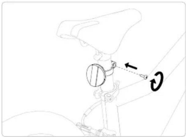
natural_image
Technical line drawing of a mechanical assembly with a belt and pulley mechanism (no text or symbols)natural_image
Line drawing of a bicycle with front wheel, rear wheel, and suspension components (no text or labels)natural_image
Silhouette of a person riding a bicycle against a solid yellow background (no text or symbols)text_image
Technical diagram of a manual crimping tool with numbered parts labeled 1, 2, and a valve mechanism.natural_image
Line drawing of a mechanical clamp or grip assembly with a tool, no text or symbols presentnatural_image
Line drawing of a robotic arm with a directional arrow indicating movement (no text or symbols)natural_image
Diagram of a bicycle climbing rope mechanism with a rotational arrow indicating motion (no text or symbols)natural_image
Simple line drawing of a mechanical component with a checkmark mark (no text or symbols)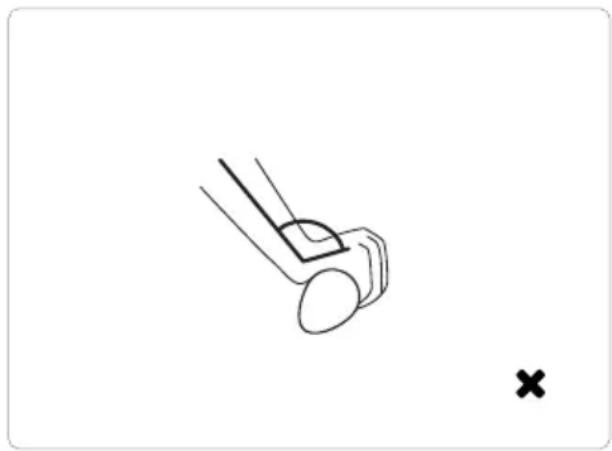
natural_image
Simple line drawing of a mechanical component with a cross mark, no text or symbols presenttext_image
Diagram of a mechanical device with labeled parts and directional arrows indicating motion or assembly.9 Propreté
text_image
Technical diagram showing mechanical assembly with labeled parts 1 and H, including a magnified inset of the component.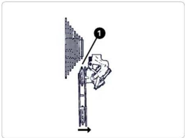
text_image
Diagram showing a hand inserting a component into a device, labeled with number 1 and directional arrow.natural_image
Line drawing of a cable connector with labeled component (no text or symbols)10 5 Freins

AVERTISSEMENT
text_image
WEAR LINERéglage des freins
natural_image
Technical line drawing of a mechanical assembly with no visible text or symbols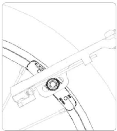
natural_image
Technical line drawing of a mechanical component with no visible text or symbols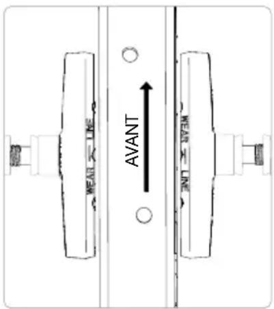
natural_image
Technical line drawing of a mechanical assembly with no visible text or symbolsnatural_image
Technical line drawing of a mechanical clamp or bracket assembly (no text or symbols)natural_image
Line drawing of a bicycle steering wheel with a labeled component (no text or symbols present)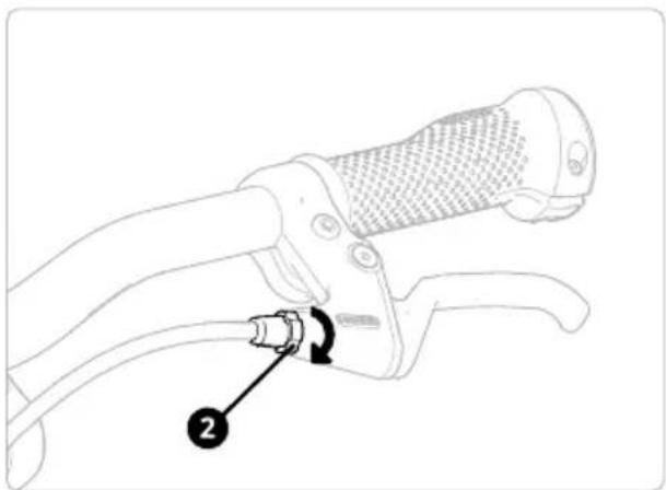
natural_image
Line drawing of a bicycle steering wheel with a lever and adjustment knob (no text or symbols)natural_image
Technical line drawing of a mechanical clamp or bracket assembly (no text or symbols)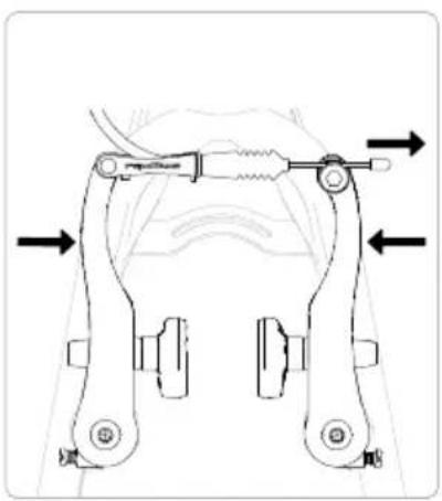
natural_image
Mechanical clamp assembly diagram showing two arms with directional arrows indicating movement (no text or labels)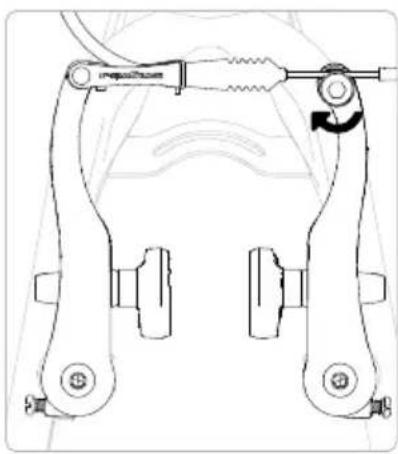
natural_image
Technical line drawing of a mechanical clamp or bracket assembly (no text or symbols)natural_image
Line drawing of a bicycle with front wheel, rear wheel, and side-mounted legs (no text or symbols)natural_image
Technical line drawing of a mechanical support structure (no text or symbols)natural_image
Line drawing of a mechanical device with a lever and cable, showing a downward force arrow (no text or symbols)natural_image
Line drawing of a bicycle steering wheel with a dollar sign and rotational arrow (no text or symbols)natural_image
Line drawing of a bicycle's steering wheel with a wrench and rotational arrow indicating clockwise motion (no text or symbols)natural_image
Pure mechanical diagram showing a lever mechanism with no text or symbols
natural_image
Pure diagram of intersecting lines and a vertical mark, no text or symbols present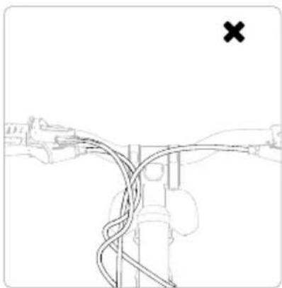
natural_image
Diagram of a bridge with cables and a marked cross symbol (no text or labels)ATTENZIONE
natural_image
Line drawing of a hand holding a cylindrical object with an arrow pointing to it, next to a pair of legs (no text or symbols)natural_image
Line drawing of a bicycle wheel with visible spokes and hub (no text or symbols)natural_image
Technical line drawing of a mechanical component with no visible text or symbolsnatural_image
Diagram of a bicycle with a key and lock mechanism, no text or symbols presentnatural_image
Diagram of bicycle wheel assembly with mechanical components and directional arrows indicating motion (no text or symbols)natural_image
Line drawing of a car interior showing a hand holding a steering wheel (no text or symbols)Aprire la leva a sgancio rapido.
natural_image
Line drawing of a bicycle suspension system with a lever and wheel (no text or symbols)natural_image
Line drawing of a bicycle seatbelt mechanism with no text or symbolsnatural_image
Technical line drawing of a bicycle wheel assembly with a rotating lever (no text or symbols)natural_image
Mechanical linkage diagram showing a lever mechanism with a rotational arrow (no text or symbols)natural_image
Illustration of a robotic arm with a tool and rotating motion arrows (no text or symbols)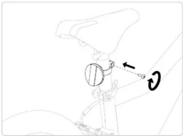
natural_image
Technical line drawing of a mechanical assembly with a circular component and directional arrows (no text or symbols)natural_image
Line drawing of a bicycle with front wheel, rear wheel, and suspension components (no text or symbols)natural_image
Silhouette of a person riding a bicycle against a solid yellow background (no text or symbols)text_image
Technical diagram of a manual crimping tool with numbered parts labeled 1, 2, and a knob indicating the grip.natural_image
Line drawing of a mechanical clamp or grip assembly with a tool, no text or symbols presentnatural_image
Line drawing of a robotic arm with a directional arrow indicating movement (no text or symbols)natural_image
Diagram of a bicycle suspension system with rope and pulley (no text or symbols)natural_image
Simple line drawing of a mechanical component with a checkmark mark (no text or symbols)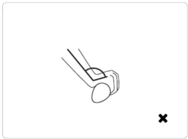
natural_image
Simple line drawing of a mechanical component with a cross mark, no text or symbols presenttext_image
Diagram of a mechanical device with labeled parts and directional arrows indicating motion or force directions.9 Pulizia
text_image
Technical diagram showing mechanical assembly with labeled parts 1 and H, including a magnified inset of the component.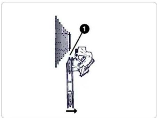
text_image
Diagram showing a hand using a tool to adjust or install a mechanical component, with labeled step 1 and directional arrow.Comando del cambio
natural_image
Line drawing of a cable connector with labeled component (no text or symbols present)10 5 Freni

ATTENZIONE
text_image
WEAR LINEnatural_image
Technical line drawing of a mechanical assembly with no visible text or symbols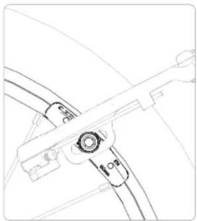
natural_image
Line drawing of a mechanical component with no visible text or symbols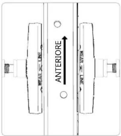
text_image
MEAN LINE ANTERIORE MEAN LINEnatural_image
Technical line drawing of a mechanical assembly with no visible text or symbolsnatural_image
Technical line drawing of a mechanical clamp or bracket assembly (no text or symbols)natural_image
Line drawing of a bicycle steering handle with a keyway and lever (no text or symbols)natural_image
Line drawing of a bicycle steering wheel with a labeled component (no text or symbols present)natural_image
Technical line drawing of a bicycle suspension frame with no text or symbolsnatural_image
Mechanical clamp assembly diagram showing two arms with directional arrows indicating movement (no text or labels)natural_image
Technical line drawing of a mechanical clamp or bracket assembly (no text or symbols)natural_image
Line drawing of a bicycle showing front wheel, rear wheel, and side-mounted legs (no text or symbols)Namestitev krmila
natural_image
Technical line drawing of a mechanical support structure (no text or symbols)natural_image
Line drawing of a mechanical device with a lever and cable, showing a downward force arrow (no text or symbols)Krmilo in nosilec krmila potisnite do konca na cev vilic.
natural_image
Line drawing of a bicycle steering wheel with a hand holding a dollar sign and a curved arrow indicating rotation (no text or symbols)natural_image
Line drawing of a bicycle steering wheel with a hand operating the lever (no text or symbols)natural_image
Pure mechanical diagram showing a lever and connecting rod (no text or symbols)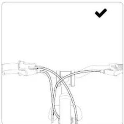
natural_image
Pure diagram of a mechanical linkage or cable system without any text, numbers, or symbols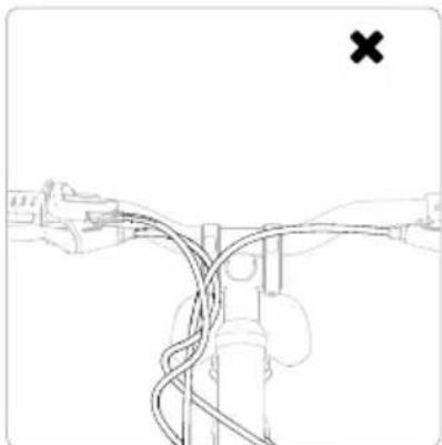
natural_image
Diagram of a mechanical linkage or cable system with no visible text or symbols
OPOZORILO
natural_image
Line drawing of a hand holding a cylindrical object with a downward arrow pointing to it, next to a pair of legs (no text or symbols)natural_image
Line drawing of a bicycle wheel with visible spokes and hub (no text or symbols)natural_image
Technical line drawing of a mechanical component with no visible text or symbolsNosilec za hitro sprostitev vri- nite skozi pesto in rahlo privijte matico.
natural_image
Diagram of a bicycle wheel with a key inserted into the wheel (no text or labels)natural_image
Diagram of bicycle wheel assembly with two arrows indicating motion direction (no text or symbols)Pritisnite zavorne roke in vsta-vite zavorni kabel.
Namestitev sedeža
natural_image
Line drawing of a car seatbelt with a hand adjusting the seatbelt (no text or symbols)natural_image
Line drawing of a bicycle suspension mechanism with a vertical shaft and arrow indicating motion (no text or symbols)natural_image
Line drawing of a bicycle seatbelt mechanism with no text or symbolsnatural_image
Mechanical diagram showing a bicycle wheel and mechanical linkage mechanism with rotation arrow (no text or symbols)natural_image
Mechanical linkage diagram showing a lever mechanism with a rotational arrow (no text or symbols)natural_image
Illustration of a robotic arm with a tool and motion arrow indicating rotation (no text or symbols)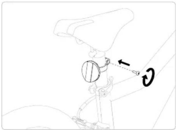
natural_image
Technical line drawing of a mechanical assembly with a circular component and directional arrows (no text or symbols)natural_image
Line drawing of a bicycle with front wheel, rear wheel, and suspension components (no text or labels)natural_image
Silhouette of a person riding a bicycle against a solid yellow background (no text or symbols)text_image
Technical diagram of a manual tool with numbered annotations indicating key componentsNastavitveni vijaki woom ORIGINAL 4, woom ORIGINAL 5 in woom ORIGINAL 6

OPOZORILO
natural_image
Line drawing of a mechanical clamp or grip assembly with a circular arrow indicating rotation (no text or symbols)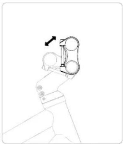
natural_image
Line drawing of a robotic arm with a directional arrow indicating movement (no text or symbols)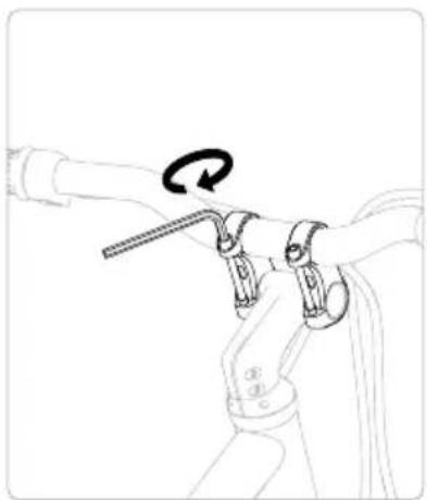
natural_image
Line drawing of a bicycle suspension mechanism with rope and pulley (no text or symbols)natural_image
Simple line drawing of a mechanical component with a checkmark (no text or symbols)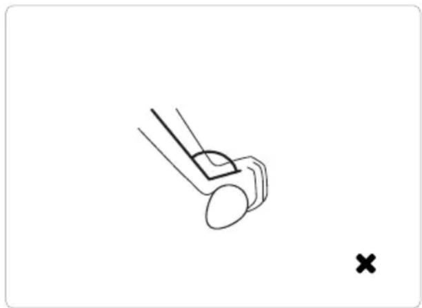
natural_image
Simple line drawing of a mechanical component with a cross mark, no text or symbols presenttext_image
Technical diagram showing a mechanical component with labeled parts 1 and 2, indicating directional movement or assembly.9 Čiščenje
text_image
Technical diagram showing mechanical assembly with labeled parts 1 and H, including a magnified inset of the component.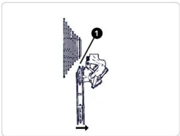
text_image
Diagram showing a hand using a tool to adjust or install a mechanical component, with labeled step 1 and directional arrow.Vrtljiva prestavna ročica
natural_image
Line drawing of a cable connector with labeled component (no text or symbols present)10 5 Zavore

OPOZORILO
text_image
WEAR LINENastavitev zavor
natural_image
Technical line drawing of a mechanical assembly with no visible text or symbols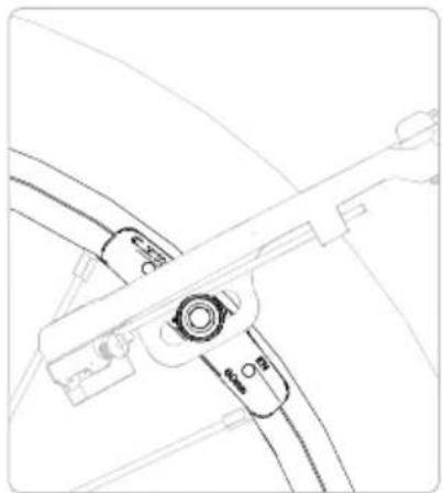
natural_image
Technical line drawing of a mechanical component with no visible text or symbols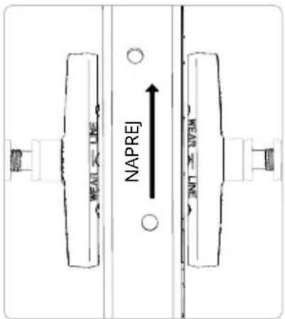
text_image
MEAL LINE NAPREnatural_image
Technical line drawing of a mechanical assembly with no visible text or symbolsPo nastavitvi zavornih oblog privijte pritrdilne vijake zavornih oblog na želeni navor in preverite delovanje zavore.
natural_image
Technical line drawing of a mechanical clamp or bracket assembly (no text or symbols)Obloge prilagodite tako, da sta leva in desna razdalja do platišča enaki.
natural_image
Line drawing of a bicycle steering wheel with a key inserted, showing no text or symbols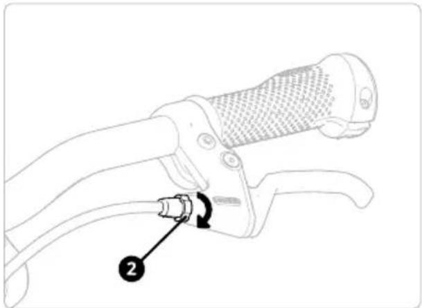
natural_image
Line drawing of a hand gripping a bicycle brake lever with a labeled component (no text or symbols present)natural_image
Technical line drawing of a mechanical clamp or bracket assembly (no text or symbols)natural_image
Technical line drawing of a mechanical clamp or bracket assembly with directional arrows indicating movement (no text or symbols present)natural_image
Technical line drawing of a mechanical clamp or bracket assembly (no text or symbols)natural_image
Line drawing of a bicycle with front wheel, rear wheel, and side-mounted accessories (no text or symbols)natural_image
Technical line drawing of a mechanical support structure (no text or symbols)natural_image
Line drawing of a mechanical device with a lever and cable, showing a downward force arrow (no text or symbols)natural_image
Line drawing of a bicycle steering wheel with a hand holding a dollar sign and a curved arrow indicating rotation (no text or symbols)natural_image
Line drawing of a bicycle steering wheel with a hand operating the lever (no text or symbols)natural_image
Pure mechanical diagram showing a lever and connecting rod (no text or symbols)
natural_image
Pure diagram of a mechanical linkage or cable system without any text, numbers, or symbols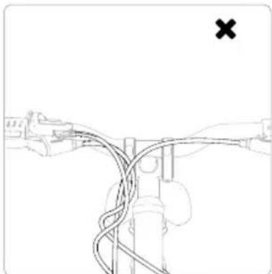
natural_image
Diagram of a mechanical linkage or cable system with no visible text or symbolsADVERTENCIA
natural_image
Diagram showing a hand holding a cylindrical object with an arrow pointing to it, next to a pair of legs (no text or symbols present)natural_image
Line drawing of a bicycle wheel with visible spokes and hub (no text or symbols)natural_image
Technical line drawing of a mechanical component with no visible text or symbolsnatural_image
Diagram of a bicycle wheel with a hand and lock mechanism, no text or symbols presentnatural_image
Diagram of bicycle wheel assembly with directional arrows indicating motion (no text or symbols)natural_image
Line drawing of a car interior showing a hand holding a steering wheel (no text or symbols)natural_image
Line drawing of a bicycle suspension mechanism with a lever and wheel (no text or symbols)natural_image
Line drawing of a bicycle seatbelt mechanism with no text or symbolsnatural_image
Technical line drawing of a bicycle wheel assembly with a rotating lever (no text or symbols)natural_image
Mechanical diagram showing a bicycle's wheel and lever mechanism with rotation arrow (no text or symbols)natural_image
Illustration of a robotic arm with a tool and motion arrow indicating rotation (no text or symbols)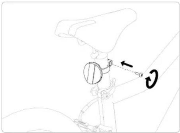
natural_image
Technical line drawing of a mechanical assembly with a circular component and directional arrows (no text or symbols)natural_image
Line drawing of a bicycle with front wheel, rear wheel, and suspension components (no text or labels)natural_image
Silhouette of a person riding a bicycle against a solid yellow background (no text or symbols)text_image
Technical diagram of a mechanical device with numbered components, likely for assembly or maintenance instructions.natural_image
Line drawing of a mechanical clamp or grip assembly with a hand holding a tool, no text or symbols presentnatural_image
Line drawing of a robotic arm with a directional arrow indicating motion (no text or symbols)natural_image
Diagram of a bicycle handle with rope and lever mechanism, no text or symbols presentnatural_image
Simple line drawing of a mechanical component with a checkmark (no text or symbols)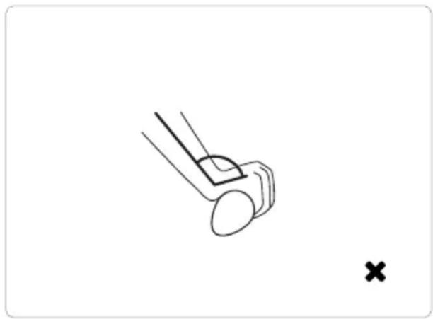
natural_image
Simple line drawing of a mechanical component with a cross mark, no text or symbols presenttext_image
Diagram of a mechanical device with labeled parts and directional arrows indicating motion or assembly.9 Limpieza
text_image
Technical diagram showing mechanical assembly with labeled parts 1 and H, including a magnified inset of the component.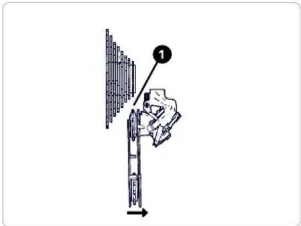
text_image
Diagram showing a hand using a tool to adjust or install a mechanical component, with labeled step 1 pointing to the component.Cambio de puño
natural_image
Line drawing of a cable connector with labeled component (no text or symbols present)10 5 Frenos

ADVERTENCIA
text_image
WEAR LINEnatural_image
Technical line drawing of a mechanical assembly with no visible text or symbols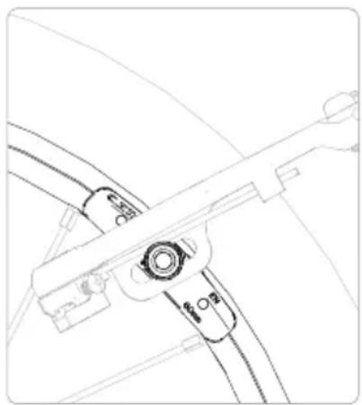
natural_image
Technical line drawing of a mechanical component with no visible text or symbols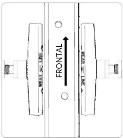
text_image
FRONTAL HEAD LINE HEAD LINEnatural_image
Technical line drawing of a mechanical assembly with no visible text or symbolsnatural_image
Technical line drawing of a mechanical clamp or bracket assembly (no text or symbols)natural_image
Line drawing of a bicycle steering wheel with a key inserted, showing no text or symbolsnatural_image
Line drawing of a bicycle steering handle with a labeled connector (no text or symbols present)natural_image
Technical line drawing of a mechanical clamp or bracket assembly (no text or symbols)natural_image
Mechanical clamp assembly diagram showing two arms with arrows indicating motion direction (no text or labels)natural_image
Technical line drawing of a mechanical clamp or bracket assembly (no text or symbols)natural_image
Line drawing of a bicycle showing front wheel, rear wheel, and side-mounted legs (no text or labels)Montaż kierownicy
natural_image
Technical line drawing of a mechanical linkage assembly (no text or symbols)natural_image
Line drawing of a mechanical device with a lever and cable, showing a downward force arrow (no text or symbols)natural_image
Line drawing of a bicycle steering wheel with a hand holding the steering wheel (no text or symbols)natural_image
Line drawing of a bicycle steering wheel with a wrench and circular motion indicator (no text or symbols)natural_image
Pure mechanical diagram showing a lever and connecting rod (no text or symbols)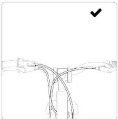
natural_image
Pure diagram of a mechanical linkage or cable system without any text, numbers, or symbols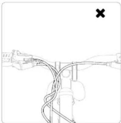
natural_image
Pure diagram of a mechanical linkage or cable system without any text, numbers, or symbols
OSTRZEŻENIE
natural_image
Simple line drawing of a hand holding a cylindrical object with an arrow pointing to it, next to a pair of legs (no text or symbols)natural_image
Line drawing of a bicycle wheel with visible spokes and hub (no text or symbols)natural_image
Technical line drawing of a mechanical component with no visible text or symbols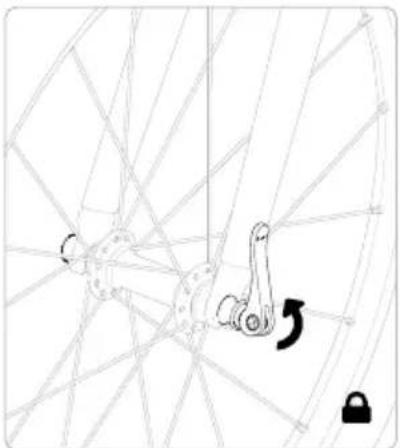
natural_image
Diagram of a bicycle wheel with a hand operating a lock mechanism, no text or symbols present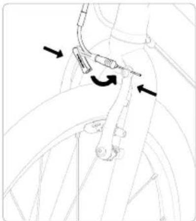
natural_image
Diagram of bicycle wheel assembly with directional arrows indicating motion (no text or symbols)natural_image
Line drawing of a car interior showing a hand holding a steering wheel (no text or symbols)natural_image
Line drawing of a bicycle support structure with a downward arrow indicating motion (no text or symbols)natural_image
Line drawing of a bicycle seatbelt mechanism with no text or symbolsnatural_image
Mechanical diagram showing a bicycle wheel and mechanical lever mechanism with rotation arrow (no text or symbols)natural_image
Mechanical linkage mechanism diagram showing a lever and wheel assembly (no text or symbols)natural_image
Illustration of a robotic arm with a tool and motion arrow indicating rotation (no text or symbols)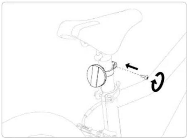
natural_image
Technical line drawing of a mechanical assembly with a circular component and directional arrows (no text or symbols)natural_image
Line drawing of a bicycle with front wheel, rear wheel, and suspension components (no text or labels)natural_image
Silhouette of a person riding a bicycle against a solid yellow background (no text or symbols)text_image
Technical diagram of a hand tool with numbered annotations indicating key componentsnatural_image
Line drawing of a mechanical clamp or grip assembly with a tool, no text or symbols presentnatural_image
Line drawing of a robotic arm with a directional arrow indicating motion (no text or symbols)natural_image
Diagram of a bicycle climbing rope with a rotating arrow indicating motion (no text or symbols)natural_image
Simple line drawing of a mechanical component with a checkmark (no text or symbols)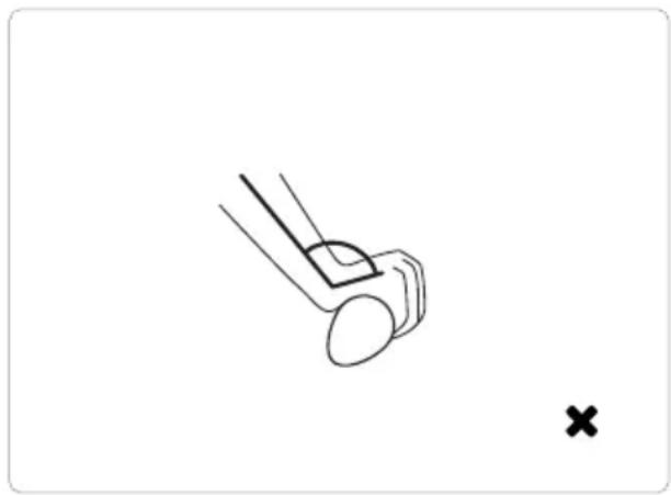
natural_image
Simple line drawing of a mechanical component with a cross mark, no text or symbols presenttext_image
Technical diagram showing a mechanical component with labeled parts 1 and 2, indicating rotational or directional movement.9 Czyszczenie
10 3 Kierownica, stery i widelec
text_image
Technical diagram showing mechanical assembly with labeled parts 1 and H, including a magnified inset of the component.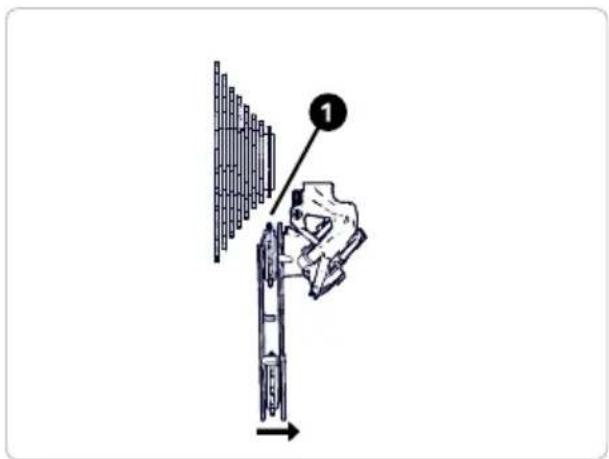
text_image
Diagram showing a hand using a tool to adjust or install a mechanical component, with labeled step 1 and directional arrow.Manetka obrotowa
natural_image
Line drawing of a cable connector with labeled component (no text or symbols present)10 5 Hamulce
OSTRZEŻENIE
text_image
WEAR LINERegulacja hamulców
natural_image
Technical line drawing of a mechanical assembly with no visible text or symbols
natural_image
Technical line drawing of a mechanical component with no visible text or symbols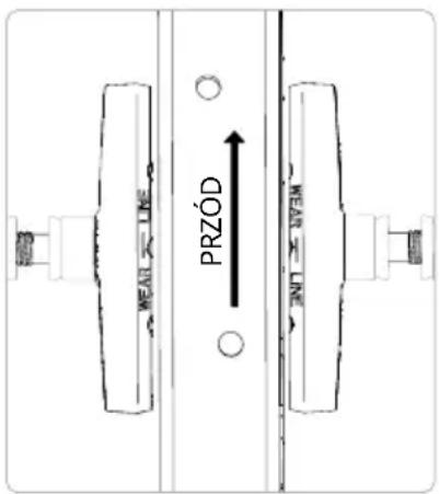
text_image
MEAN LINE PRZÓD NEAMnatural_image
Technical line drawing of a mechanical assembly with no visible text or symbolsnatural_image
Technical line drawing of a mechanical clamp or bracket assembly (no text or symbols)natural_image
Line drawing of a bicycle steering wheel with a handle and lever, labeled with number 1 (no text or symbols on the diagram itself)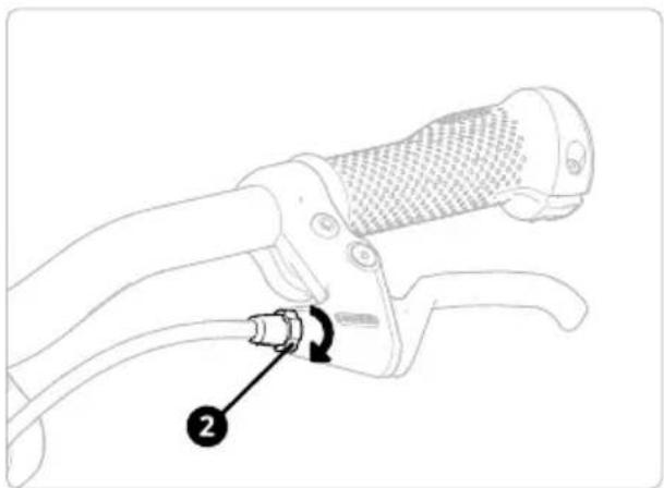
natural_image
Line drawing of a hand gripping a bicycle brake lever with a labeled component (no text or symbols present)natural_image
Technical line drawing of a mechanical clamp or bracket assembly (no text or symbols)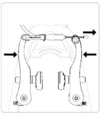
natural_image
Mechanical clamp assembly diagram showing two arms with arrows indicating movement or force direction (no text or labels)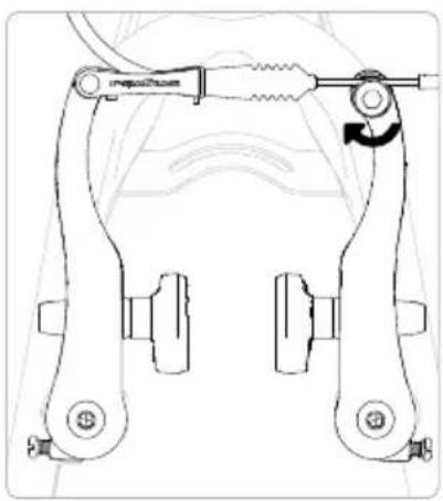
natural_image
Technical line drawing of a mechanical clamp or bracket assembly (no text or symbols)natural_image
Line drawing of a bicycle showing front wheel, rear wheel, and side-mounted legs (no text or symbols)natural_image
Technical line drawing of a mechanical support frame assembly (no text or symbols)natural_image
Line drawing of a mechanical device with a lever and cable, showing a downward force arrow (no text or symbols)natural_image
Line drawing of a bicycle steering wheel with a hand holding a dollar sign and a curved arrow indicating rotation (no text or symbols)natural_image
Line drawing of a bicycle steering wheel with a hand operating the lever (no text or symbols)natural_image
Pure mechanical diagram showing a lever and connecting components without any text or symbols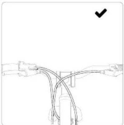
natural_image
Pure diagram of a mechanical linkage or cable system without any text, numbers, or symbols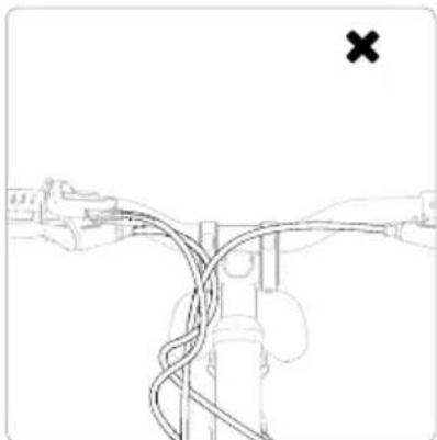
natural_image
Diagram of a mechanical linkage or cable assembly with no visible text or symbols
AVERTISMENT
natural_image
Diagram showing a hand holding a cylindrical object with an arrow pointing to it, next to a pair of legs (no text or symbols present)natural_image
Line drawing of a bicycle wheel with visible spokes and hub (no text or symbols)natural_image
Diagram of a mechanical assembly with labeled components and directional arrows (no readable text or symbols)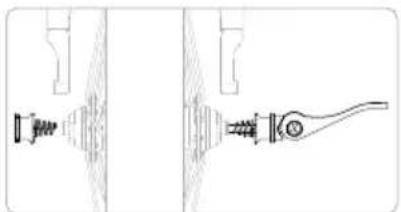
natural_image
Technical line drawing of a mechanical component with no visible text or symbolsnatural_image
Diagram of a bicycle wheel with a key inserted into the frame, showing no text or symbols.natural_image
Line drawing of a bicycle tire with a cable and connector, showing motion arrows (no text or symbols)natural_image
Line drawing of a car interior showing a hand holding a steering wheel (no text or symbols)natural_image
Line drawing of a bicycle support structure with a downward arrow indicating motion (no text or symbols)natural_image
Line drawing of a bicycle seatbelt mechanism with no text or symbolsnatural_image
Technical line drawing of a bicycle wheel assembly with a rotating lever (no text or symbols)natural_image
Mechanical linkage diagram showing a lever mechanism with a rotational arrow (no text or symbols)natural_image
Technical line drawing showing two mechanical assembly steps with rotational arrows and adjustment circles (no text or symbols)natural_image
Line drawing of a bicycle with front wheel, rear wheel, and suspension components (no text or labels)natural_image
Silhouette of a person riding a bicycle against a yellow background (no text or symbols)text_image
Technical diagram of a manual tool with numbered annotations indicating key componentsnatural_image
Diagram of a hand holding a tool with a circular arrow indicating rotation (no text or symbols present)natural_image
Line drawing of a robotic arm with a directional arrow indicating movement (no text or symbols)natural_image
Line drawing of a bicycle climbing rope with a circular motion arrow indicating rotational motion (no text or symbols)natural_image
Simple line drawing of a mechanical component with a checkmark (no text or symbols)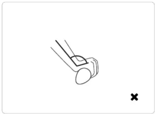
natural_image
Simple line drawing of a mechanical component with a cross mark, no text or symbols presenttext_image
Diagram of a mechanical device with labeled parts and directional arrows indicating motion or assembly.9 Curățare
text_image
Technical diagram showing mechanical assembly with labeled parts 1 and H, including a magnified inset of the component.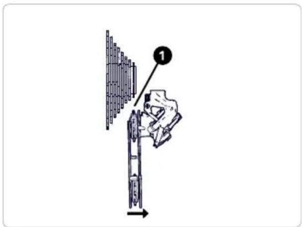
text_image
Diagram showing a hand using a tool to adjust or install a mechanical component, with labeled step 1 and directional arrow.Comutator răsucire
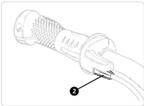
natural_image
Line drawing of a cable connector with labeled component (no text or symbols)10 5 Frâne

AVERTISMENT
text_image
WEAR LINEReglarea frânelor
natural_image
Technical line drawing of a mechanical assembly with no visible text or symbols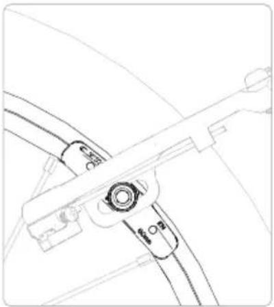
natural_image
Line drawing of a car wheel assembly with no visible text or symbols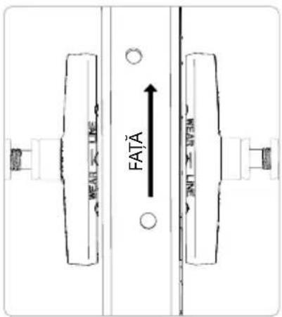
text_image
HEAD LINE FATÄ HEAD LINEnatural_image
Technical line drawing of a mechanical assembly with no visible text or symbolsnatural_image
Technical line drawing of a mechanical clamp or bracket assembly (no text or symbols)natural_image
Line drawing of a bicycle steering wheel with a handle and lever (no text or symbols)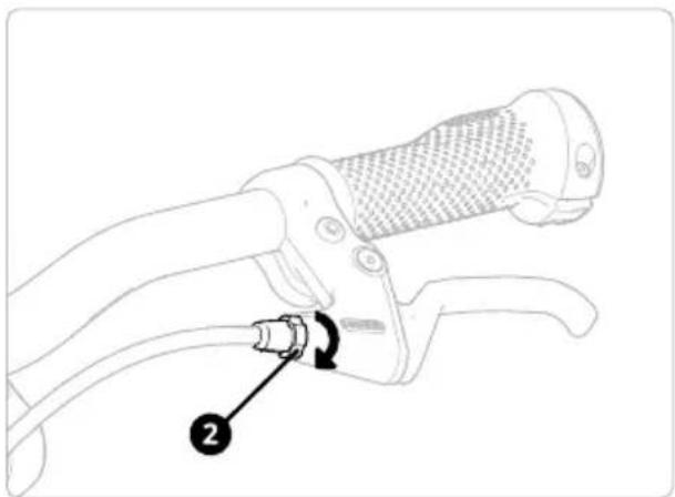
natural_image
Line drawing of a hand gripping a bicycle brake lever with a labeled component (no text or symbols present)natural_image
Technical line drawing of a mechanical clamp or bracket assembly (no text or symbols)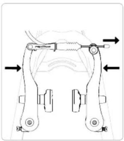
natural_image
Mechanical clamp assembly diagram showing two arms with arrows indicating motion direction (no text or labels)
natural_image
Technical line drawing of a mechanical clamp or bracket assembly (no text or symbols)natural_image
Line drawing of a bicycle showing front wheel, rear wheel, and side-mounted legs (no text or symbols)Montáž řídítek
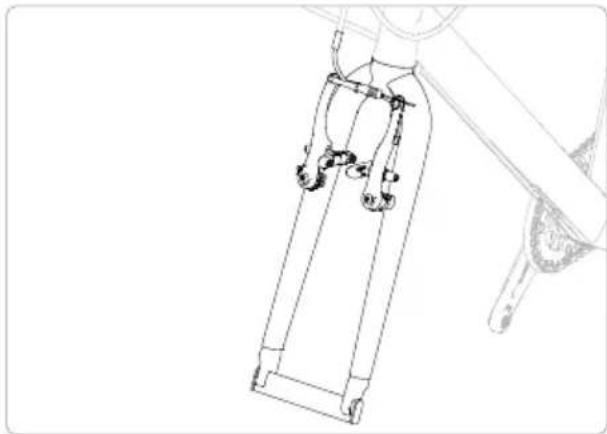
natural_image
Technical line drawing of a mechanical linkage assembly (no text or symbols)natural_image
Line drawing of a mechanical device with a lever and cable, showing a downward force arrow (no text or symbols)natural_image
Line drawing of a bicycle steering wheel with a hand holding a key and a circular arrow indicating rotation (no text or symbols)natural_image
Line drawing of a bicycle steering wheel with a gear shift and rotational arrow (no text or symbols)natural_image
Pure mechanical diagram showing a lever and connecting rod (no text or symbols)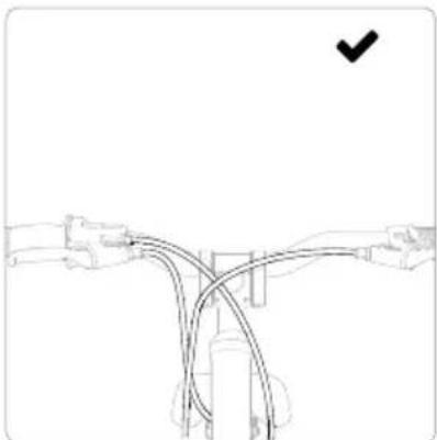
natural_image
Pure diagram of a mechanical or electrical component with no text, numbers, or symbols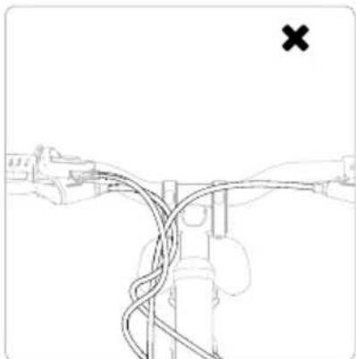
natural_image
Diagram of a mechanical linkage or cable system with no visible text or symbols
VAROVÁNÍ
natural_image
Line drawing of a mechanical component with a labeled arrow pointing to a cylindrical part (no text or symbols present)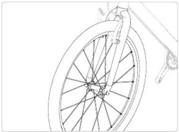
natural_image
Line drawing of a bicycle wheel with visible spokes and hub, no text or symbols presentnatural_image
Diagram of a mechanical assembly with labeled components and directional arrows (no readable text or symbols)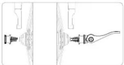
natural_image
Technical line drawing of a mechanical component with no visible text or symbols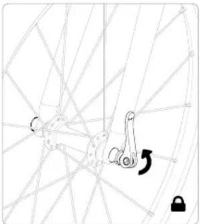
natural_image
Diagram of a bicycle wheel with a key inserted into the frame, showing no text or symbols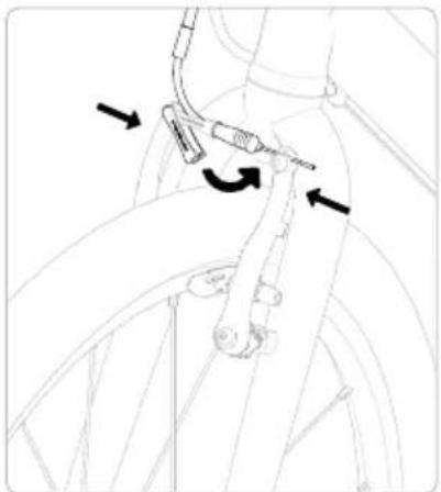
natural_image
Line drawing of a bicycle tire with a tool inserted, showing motion arrows (no text or symbols)natural_image
Line drawing of a car interior showing a hand holding a steering wheel (no text or symbols)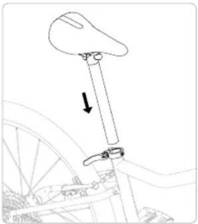
natural_image
Line drawing of a bicycle support structure with a downward arrow indicating motion (no text or symbols)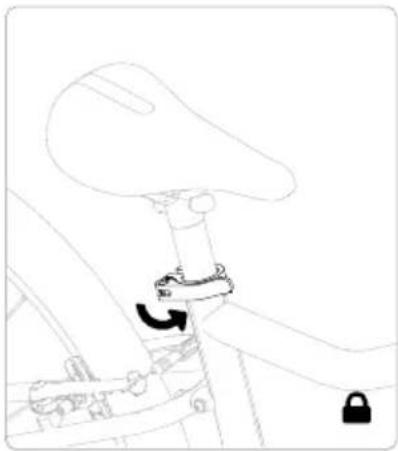
natural_image
Line drawing of a bicycle seatbelt mechanism with no text or symbolsnatural_image
Technical line drawing of a bicycle wheel assembly with a rotating lever (no text or symbols)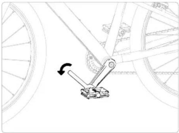
natural_image
Mechanical linkage diagram showing a lever mechanism with a rotational arrow (no text or symbols)natural_image
Line drawing of a robotic arm with a tool inserted, showing rotational motion (no text or symbols)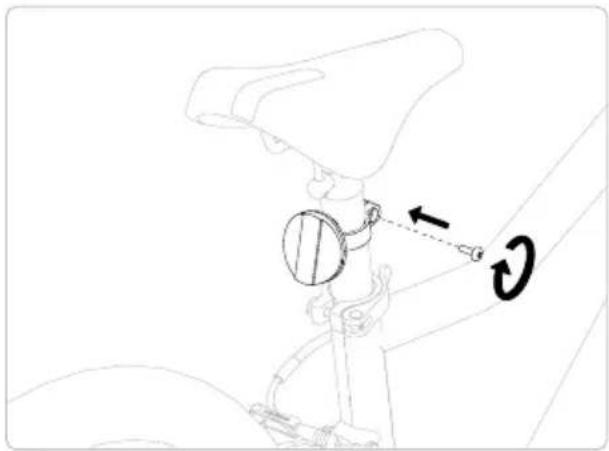
natural_image
Technical line drawing of a mechanical assembly with a circular component and directional arrows (no text or symbols)natural_image
Line drawing of a bicycle with front wheel, rear wheel, and suspension components (no text or labels)natural_image
Silhouette of a person riding a bicycle against a solid yellow background (no text or symbols)text_image
Technical diagram of a hand tool with numbered annotations indicating key componentsStavěcí šrouby na modelech woom ORIGINAL 4, woom ORIGINAL 5 a woom ORIGINAL 6

VAROVÁNÍ
natural_image
Line drawing of a mechanical clamp or tool with a handle and spring, no text or symbols presentnatural_image
Line drawing of a robotic arm with a directional arrow indicating movement (no text or symbols)natural_image
Diagram of a mechanical clamp or lever mechanism with a rotating arrow indicating rotational motion (no text or symbols present)natural_image
Simple line drawing of a mechanical component with a checkmark (no text or symbols)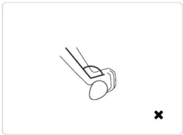
natural_image
Simple line drawing of a mechanical component with a cross mark, no text or symbols presenttext_image
Diagram of a mechanical device with labeled parts and directional arrows indicating motion or assembly.9 Čištění
text_image
Technical diagram showing mechanical assembly with labeled parts 1 and H, including a magnified inset of the component.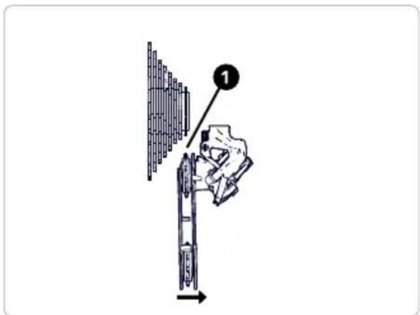
text_image
Diagram showing a hand using a tool to adjust or install a mechanical component, with labeled step 1 and directional arrow.Otočné řazení
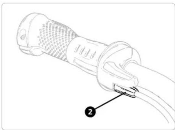
natural_image
Line drawing of a cable connector with labeled component (no text or symbols present)10 5 Brzdy
VAROVÁNÍ
text_image
WEAR LINESeřízení brzd
natural_image
Technical line drawing of a mechanical assembly with no visible text or symbols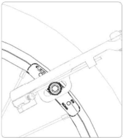
natural_image
Technical line drawing of a mechanical component with no visible text or symbols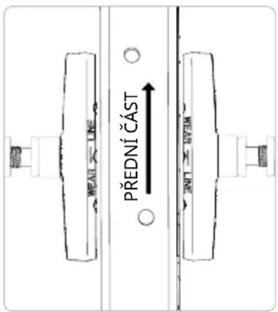
natural_image
Technical line drawing of a mechanical assembly with no visible text or symbolsnatural_image
Technical line drawing of a mechanical clamp or bracket assembly (no text or symbols)natural_image
Line drawing of a bicycle steering wheel with a key inserted, showing no text or symbols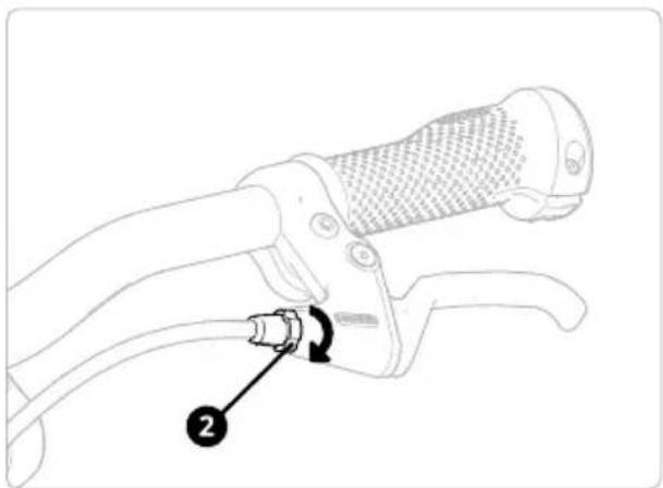
natural_image
Line drawing of a bicycle steering wheel with a cable and adjustment knob (no text or symbols)natural_image
Technical line drawing of a mechanical clamp or bracket assembly (no text or symbols)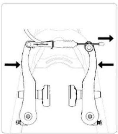
natural_image
Mechanical clamp assembly diagram showing two arms with directional arrows indicating movement (no text or labels)