Lithium 10A - Battery charger Optimate - Free user manual and instructions
Find the device manual for free Lithium 10A Optimate in PDF.


User questions about Lithium 10A Optimate
0 question about this device. Answer the ones you know or ask your own.
Ask a new question about this device
Download the instructions for your Battery charger in PDF format for free! Find your manual Lithium 10A - Optimate and take your electronic device back in hand. On this page are published all the documents necessary for the use of your device. Lithium 10A by Optimate.
USER MANUAL Lithium 10A Optimate
0.66A @ 240VAC 1.59A @ 100VAC
DC: 120W →12.8V 9.5A
Thermally adjusted
1234
12.8V / 13.2V / 4s LiFePO _4 / Lithium Ferrous Phosphate 2Ah <-> 120Ah
INSTRUCTIONS FOR USE
IMPORTANT: Read completely before charging
MODE D'EMPLOI
SAVE THESE INSTRUCTIONS.
AUTOMATIC CHARGER ONLY FOR 12.8V LIFEPO4 (LITHIUM FERROUS PHOSPHATE / LITHIUM IRON PHOSPHATE) BATTERIES.
EN
DO NOT USE FOR NiCd, NiMH, Lead-Acid or any other type of Li-Ion or NON-RECHARGEABLE BATTERIES.
- CAUTION : DO NOT CONNECT TO GROUND.
- For indoor use only. Do not expose charger to rain or snow.
- Use of an attachment not recommended or sold by the battery charger manufacturer may result in a risk of fire, electric shock, or injury to persons.
- To reduce risk of damage to electric plug and cord, pull by plug rather than cord when disconnecting charger.
- An extension cord should not be used unless absolutely necessary. Use of improper extension cord could result in a risk of fire and electric shock. If extension cord must be used make sure that :
a) pins on plug of extension cord are the same number, size and shape as those of plug on charger, b) the extension cord is property wired and in good electrical condition, and c) the conductor wire size is large enough for the AC ampere rating of the charger as specified in the table below.
| AC INPUT RATING IN AMPERESEqual to or greater than But less than | LENGTH OFCORD, FEET (m) | AWGSIZE OFCORD | |
| 2A 3A 25 (17.6) | 50 (15.2)100 (30.5) | 181814 | |
- Do not operate charger with damaged cord or plug - replace the cord or plug immediately.
- Do not operate charger if it has received a sharp blow, been dropped, or otherwise damaged in any way; take it to a qualified serviceman.
- Do not disassemble charger; take it to a qualified serviceman when service or repair is required.
Incorrect reassembly may result in a risk of electric shock or fire. - To reduce risk of electric shock, unplug the charger from outlet before attempting any maintenance or cleaning.
Turning off controls will not reduce this risk. Clean only with slightly moist, not wet, cloth. Do not use solvents. - warning - risk of explosive gases. a) working in vicinity of a lead-acid battery is dangerous. Batteries generate explosive gases during normal battery operation. for this reason, it is of utmost importance that you follow the instructions each time you use the charger. b) To reduce risk of battery explosion, follow these instructions and those published by the battery manufacturer and manufacturer of any equipment you intend to use in vicinity of the battery. Review cautionary marking on these products and on engine.
11. PERSONAL PRECAUTIONS.
a) Someone should be within range of your voice OR close enough to come to your aid when you work near a battery. b) Have plenty of fresh water and soap nearby in case battery acid contacts skin, clothing or eyes. c) Wear complete eye protection and clothing protection. Avoid touching eyes while working near a battery. d) If battery acid contacts or enters eye, flood eye with cold running water for at least 10 minutes and get medical attention immediately. If battery acid contacts skin or clothing, wash immediately with soap & water. If acid enters an eye, immediately flood eye with running cold water for at least 10 minutes & get medical attention immediately. e) NEVER smoke or allow a spark or flame in vicinity of battery or engine. f) Be extra cautious to reduce risk of dropping a metal tool onto battery. It might spark or short-circuit battery or other electrical part that may cause explosion. g) Remove personal metal items such as rings, bracelets, necklaces, and watches when working with a battery. A battery can produce a short-circuit current high enough to weld a ring or the like to metal, causing a severe burn. i) NEVER charge a frozen battery.
12. PREPARING TO CHARGE
a) If necessary to remove battery from vehicle to charge, always remove grounded terminal from battery first.
Make sure all accessories in the vehicle are off, so as not to cause an arc.
b) Be sure area around battery is well ventilated while battery is being charged. Gas can be forcefully blown away by using a piece of cardboard or other non-metallic material as a fan.
c) Clean battery terminals. Be careful to keep corrosion from coming in contact with eyes. d) Study all battery manufacturer's specific precautions such as removing or not removing cell caps while charging and recommended rates of charge. e) Determine voltage of battery by referring to vehicle or other user's manual and before making the battery connections, make sure that the voltage of the battery you are going to charge matches the output voltage of the charger.
13. CHARGER LOCATION.
a) Locate charger as far away from battery as DC cables permit. b) Never place charger directly above battery being charged; gases from battery will corrode and damage the charger. c) Never allow battery acid to drip on charger when reading gravity or filling battery. Do not operate charger in a closed-in area or restrict ventilation in any way.
d) Do not set a battery on top of charger. IMPORTANT : Place charger on a hard flat surface or mount onto a vertical surface. Do not place on plastic, leather or textile surface.
14. DC CONNECTION PRECAUTIONS
a) Connect and disconnect DC output clips only after removing AC cord from electric outlet. Never allow clips to touch each other, however should this happen no damage will result to the charger circuit & the automatic charging programme will just reset to «start». b) Attach clips to battery and chassis as indicated in 15(e), 15(f), and 16(b) through 16(d).
NOTE : This battery charger has an automatic safety feature that will prevent it from operating if the battery has been inversely connected.
Remove AC cord from electrical outlet, disconnect the battery clips, then reconnect correctly according to the instructions below.
15. FOLLOW THESE STEPS WHEN BATTERY IS INSTALLED IN VEHICLE. A SPARK NEAR A BATTERY MAY CAUSE BATTERY EXPLOSION. TO REDUCE RISK OF A SPARK NEAR BATTERY :
a) Position AC and DC cords so as to reduce risk of damage by hood, door or moving engine part. b) Stay clear of fan -blades, belts,pulleys,and other parts that can cause injury to persons. c) Check polarity of battery posts.POSITIVE (POS, P, +) battery post usually has larger diameter than NEGATIVE (NEG, N,−) post. d) Determine which post of battery is grounded (connected) to the chassis. If negative post is grounded to chassis (as in most vehicles),see (e). If positive post is grounded to the chassis,see (f). e) For negative-grounded vehicle, connect POSITIVE (RED) clip from battery charger to POSITIVE (POS, P, + ) ungrounded post of battery. Connect NEGATIVE (BLACK) clip to vehicle chassis or engine block away from battery. Do not connect clip to carburetor, fuel lines, or sheet-metal body parts. Connect to a heavy gage metal part of the frame or engine block. f) For positive-grounded vehicle, connect NEGATIVE (BLACK) clip from battery charger to NEGATIVE (NEG. N , −) ungrounded post of battery. Connect POSITIVE (RED) clip to vehicle chassis or engine block away from battery. Do not connect clip to carburetor, fuel lines, or sheet-metal body parts. Connect to a heavy gage metal part of the frame or engine block. g) When disconnecting charger, turn switches to off, disconnect AC cord,remove clip from vehicle chassis,and then remove clip from battery terminal. h) See operating instructions for length of charge information.
16. FOLLOW THESE STEPS WHEN BATTERY IS OUTSIDE VEHICLE. A SPARK NEAR THE BATTERY MAY CAUSE BATTERY EXPLOSION. TO REDUCE RISK OF A SPARK NEAR BATTERY :
a) Check polarity of battery posts. POSITIVE (POS, P, +) battery post usually has a larger diameter than NEGATIVE (NEG,N, -) post. b) This battery charger has an automatic safety feature that will prevent it from operating if the battery has been inversely connected. The charger does allow charge current unless a voltage of at least 0.5V is sensed.
c) Connect POSITIVE (RED) charger clip to POSITIVE (POS, P, +) post of battery. d) Connect NEGATIVE (BLACK) charger clip to NEGATIVE (NEG, N, -) battery post of the battery. e) Do not face battery when making final connection.
f) When disconnecting charger, always do so in reverse sequence of connecting procedure & break first connection while as far away from battery as practical.
g) A marine (boat) battery must be removed & charged on shore. To charge it on board requires equipment specially designed for marine use.
DO NOT USE FOR NiCd, NiMH, Lead-Acid or any other type of Li-Ion or NON-RECHARGEABLE BATTERIES.
IMPORTANT: READ THE FOLLOWING INSTRUCTIONS BEFORE OPERATING THIS CHARGER.
EN
This appliance can be used by children aged from 8 years and above and persons with reduced physical, sensory or mental capabilities or lack of experience and knowledge if they have been given supervision or instruction concerning use of the appliance in a safe way and understand the hazards involved. Children shall not play with the appliance. Cleaning and user maintenance shall not be made by children without supervision.
SAFETY WARNING AND NOTES: BATTERIES EMIT EXPLOSIVE GASES - PREVENT FLAME OR SPARKS NEAR BATTERIES. CHARGE BATTERY IN A WELL VENTILATED AREA. Use the charger only if the input and output leads and connectors are in good, undamaged condition. If the input cable is damaged, it is essential to have it replaced without delay by the manufacturer, his authorised service agent or a qualified workshop, to avoid danger. Protect your charger from damp and humid conditions both during use and in storage. Damage resulting from corrosion, oxidation or internal electrical short-circuiting is not covered by warranty. Distance the charger from the battery during charging to avoid contamination by or exposure to acid or acidic vapours. If using it in the horizontal orientation, place the charger on a hard, flat surface, but NOT on plastic, textile or leather. Use the fixing holes provided in the enclosure base to attach the charger to any convenient, sound vertical surface.
EXPOSURE TO LIQUIDS: This charger is designed to withstand exposure to liquids accidentally spilled or splashed onto the casing from above during indoor use. Prolonged exposure to falling rain is inadvisable and longer service life will be obtained by minimizing such exposure. Failure of the charger due to oxidation resulting from the eventual penetration of liquid into the electronic components, connectors or plugs, is not covered by warranty.
CONNECTING THE CHARGER TO THE BATTERY
-
Disconnect AC power supply before making or breaking DC / battery connections.
-
If charging a battery in the vehicle with the battery clips, before making connections, first check that the battery clips can be safely and securely positioned clear from surrounding wiring, metal tubing or the chassis. Make connections in the following order:
First connect to the battery terminal not connected to the chassis (normally positive), then connect the other battery clip (normally negative) to the chassis well away from the battery and fuel line. Always disconnect in reverse sequence.
- When charging a battery out of the vehicle with the battery clips, place it in a well ventilated area. Connect the charger to the battery: RED clamp to POSITIVE (POS, P or +) terminal and BLACK clamp to NEGATIVE (NEG, N or −) terminal. Make sure the connections are firm and secure. Good contact is important.
PROCEEDING TO CHARGE
CHARGING TIME - For batteries rated from 2.5Ah to 10Ah: 60 to 120 minutes to progress to the voltage retention test.
For batteries rated above 10Ah: approximately 20% of the battery's Ah rating, so a 50Ah battery should take no more than about 10 hours to progress to the voltage retention test. Deep discharged batteries may take longer.
safeT^o - The safeT^o program limits charge current if the temperature measured at the OptiMate Lithium is below 0^ / 32^ or above 45^ / 113^ . If the temperature was initially below 0^ / 32^ charge current is limited only for the first hour after which the battery is expected to have increased its internal temperature within the normal temperature zone. See page 2 for temperature ( ^/^ ) and corresponding Ampére (A) values. Within the normal temperature range the ampmatic^TM LiFePO_4 specific program automatically determines the most efficient rate of charge current for the connected battery, according to its state of charge, state of
health, and electrical storage (Ah) capacity. The delivered current may be anywhere from 2.5A to 9.5A.
VERY FLAT NEGLECTED BATTERIES: Pay particularly close attention to the following A LiFePO _4 battery left deep-discharged for an extended period may develop permanent damage in one or more cells. Such batteries may heat up excessively during charging. During the SAVE mode the program limits charge current if the voltage is below nominal (12.8V) and the program should detect obvious cell damage and will automatically suspend charging, but the higher the cell count in parallel the more difficult it is to detect a bad cell. ALWAYS monitor the battery temperature during the first hour, then hourly there-after. If at any time the battery is uncomfortably hot to touch or you notice any unusual signs, DISCONNECT THE CHARGER IMMEDIATELY.
STEP 1 CONNECT TO THE BATTERY
Protection
BMS RESET
text_image
1a 1b 2 TUNE TUNE BMS reset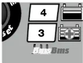
text_image
4 3 Bms-BmsBMS RESET:
MANUAL CHARGE ACTIVATION:
WARNING: Prior to and following MANUAL CHARGE ACTIVATION monitor the battery temperature. If at any time the battery is uncomfortably hot to touch or you notice any unusual signs, DISCONNECT THE CHARGER IMMEDIATELY.
SELECTABLE MODES:
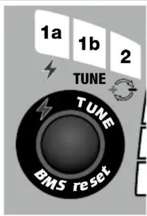
CHARGE - LED #1a - is the default mode following connection to AC power.
TUNE - LED #1b - provides a stable voltage of 13.6V to the battery with up to 8A of current available, to prevent the battery from losing charge during diagnosis/troubleshooting and/or when vehicle circuitry is operated without the engine running. TUNE mode can be activated during CHARGE mode, if the charger has determined that the battery has reached approximately 75% state of charge (STEP 8) and is now able to support additional or intermittent high current draw that may occur during diagnosis/troubleshooting. See page 6.
LED #2 REVERSE POLARITY: Lights when the battery connections are incorrect. The charger is electronically protected so no damage will result, and the output will remain disabled until the connections are corrected.
AUTOMATIC ACTIVATION: The CHARGE mode automatically activates and LED #1a brightens if the connected battery voltage is at least 0.5 Volt. The program proceeds directly to STEP 2 & 3.
MANUAL ACTIVATION: may be required for batteries with integrated battery management system (BMS) that protects against deep discharge.
Press the pushbutton. LED #3 blinks once per second as a special BMS reset pulse is delivered. When the OptiMate Lithium senses the battery BMS has reset, LED #3 turns full on, the reset pulses will automatically discontinue and the program will continue to STEP 5. Remove finger from pushbutton.
BMS not resetting / LED #3 lights briefly and then turns off: A deep discharged battery may not hold sufficient voltage to power its own BMS system.
MANUAL CHARGE ACTIVATION: Place and hold finger on BMS reset button for 10 or more seconds until LED #3 turns full on. The charge program now automatically starts at STEP 4 or 5.
ERROR! LED #8 flashes/blinks: 1) Battery is connected in reverse polarity. Correct the connections and try again. 2) The vehicle circuitry powered by the battery is preventing the pulse from being delivered. Disconnect the battery from the vehicle and try again. 3) The battery's BMS or the battery itself may have suffered damage. Have the battery professionally assessed. 4) The charger cannot deliver current as the ambient temperature may be out of safe charging range for the battery. See page 2 for temperature (°C/°F) and corresponding Ampére (A) values.
| STEP2 & 3Preparing to charge | STEP 2Battery SOC checkSTEP 3Temp° check | Immediately following connection to a battery there may be a 1-2 second delay before charging progresses, during which time:Battery State Of Charge is measured to determine charge requirement and duration of the State Of Health test in STEP 9. A low battery will be tested for 12 hours.safeTo: Ambient temperature is measured to determine safe charge current parameters. See page 2 for temperature (°C/°F) and corresponding Ampere (A) values. |
| STEP4, 5 & 6SAVEState Of Charge:Less than 50% | LED #3 : RED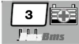 Time to save a batterySTEP 4Below 8.8VSTEP 58.8V to 13.1VFollowing a BMS resetSTEP 6TEST cell damage Time to save a batterySTEP 4Below 8.8VSTEP 58.8V to 13.1VFollowing a BMS resetSTEP 6TEST cell damage | The battery SAVE mode engages if the battery is less than 50% charged OR voltage is between 0.5 to 13.1 Volt.IMPORTANT: Read the section VERY FLAT NEGLECTED BATTERIES on the preceding page.A very flat battery should progress to STEP 7 within 4 hours, unless damage has been detected, then charging will be suspended and TEST LED #8 (red) will flash rapidly, indicating the battery may have suffered permanent damage or a professional assessment is required.VERY LOW VOLTAGE SAVE: Current starts at 0.6A and will increase to 1.25A depending on charge progress. If the voltage did not rise above 8.8V within 2 hours, charging will be suspended and the TEST LED #8 (red) will flash, indicating the battery may have suffered permanent damage or a professional assessment is required.LOW VOLTAGE SAVE:Charge current is increased to 2.5A*. The battery's charge acceptance is monitored for unusual behaviour.*Charge current is increased to 6A following a BMS reset.A deep discharged battery that may not hold sufficient voltage to power its own BMS system will automatically receive repeated BMS reset pulses during SAVE mode so that charging may continue. If charging did not continue, use the MANUAL CHARGE ACTIVATION mode described under STEP 1.TESTING (2 min) - The battery's ability to hold charge is monitored. A healthy LiFePO4 battery will progress to STEP 7, otherwise charging will be suspended and TEST LED #8 (red) will flash rapidly, indicating the battery may have suffered permanent damage or a professional assessment is required. |
| STEP 7CHARGEState Of Charge:50%-75% | LED #4 : BLUE[IMAGE] | TheampmaticTM CHARGE program automatically determines the most efficient rate of charge current for the connected battery, according to its state of charge, state of health, and electrical storage (Ah) capacity. The delivered current may be anywhere from 2.5A to 9.5A (within normalsafeTo temperatures, see page 5). For batteries with an electrical storage (Ah) capacity less than 10Ah charge current is automatically adjusted lower to an average equal to battery Ah capacity, e.g. a 2.5Ah / 2500mAh battery receive an average of 2.5 Amps.NOTE: For safety reasons there is an overall charge time limit of 24 hours up to STEP 7. |
| STEP 8OPTIMIZE cell balancingState Of Charge:75%-100% | LED #5 : BLUE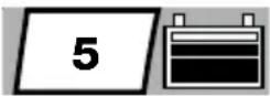 | This final charge mode starts when the voltage has reached 14.4V for the first time during STEP 7.TheampmaticTMcurrent control program now delivers pulses of current to equalise the individual cells within the battery and optimizes charge level.Minimum charge time is influenced by initial State Of Charge as measured during STEP 3, varying between 10 minutes for a battery with 80% or higher state of charge to the maximum of 120 minutes for a battery with 40% or less. |
| STEP 9State Of Charge TEST | LED #6 : GREEN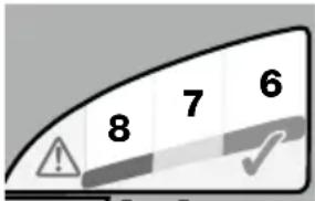 | TEST after charge : Delivery of current to the battery is interrupted for 30 minutes** to allow the program to determine the battery's ability to retain charge.** IF charging started in SAVE mode (LED #3) the voltage retention test is extended to 12 hours to confirm battery health.LED #6 (green) will remain on for batteries able to hold 90% or higher state of charge (SOC%), otherwise the TEST result is adjusted lower (LED #7, LED #8) in real time according to the measured battery voltage. Consult the table on page 2 to match TEST LED indication to an estimated state of charge percentage (SOC%).Also read section “NOTES ON TEST RESULTS” below. |
| STEP 10OptiMATE 24-7Maintain | LED #6 / 7 / 8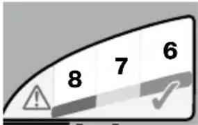 | MAINTENANCE CHARGE: LED #6 / 7 / 8 steady on according to final voltage measured at termination of STEP 9.The MAINTENANCE CHARGE CYCLEconsists of 30 minute charge periods followed by and alternating with a 30 minute ‘rest’ periods, during which there is no charge current.During the30 minute*charge cycles current is delivered only if the battery has lost charge.* The charge cycle may be extended if high current draw is sensed and will continue until current demand once again reduces below 1A.TheBATTERY REFRESH CYCLEis performed if the charger detects the battery has suddenly lost significant charge. The program reverts to STEP 8 (LED #5) before returning to STEP 9 and STEP 10.Read section MAINTAINING A LITHIUM BATTERY FOR EXTENDED PERIODS. |
| TUNEImportant!A Lithium battery has less Amp-hour capacity than a standard battery. Use only when battery is 75% or more charged! | LED #1b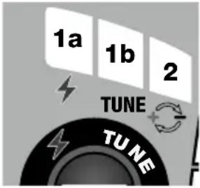 | TUNE battery support mode, for engine tuning or diagnosis : A fixed 13.6V is delivered, with up to 8 Amps of current available to prevent or slow down battery discharge.TO ACTIVATE: With OptiMate Lithium connected and charge mode in STEP 8 or higher, press button for 3 seconds until LED #1b and LED #6, #7 and #8 light together.LED indication during TUNE mode:LED #6, #7, #8 = power draw is normal.LED #7 & #8 = Power draw is exceeding what OptiMate Lithium can deliver on its own, the battery also delivering power and discharging.LED #8 = WARNING! Battery is down to 10% SOC, with an estimated 1-2 minutes support remaining. If battery loses further charge TUNE mode will automatically de-activate and CHARGE STEP 4 (LED #3) will re-activate.TO DE-ACTIVATE MANUALLY and return to CHARGE program : Place and hold finger on Select button. After 3 seconds standard charging & 24-7 maintenance will resume. |
LEDs #6 / 7 / 8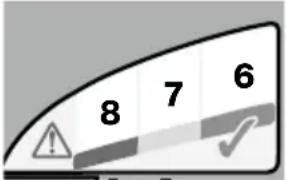 |
NOTES ON TEST RESULTS: The voltage of a cooled battery is directly proportional to its State Of Charge percentage (SOC%). Immediately following charging a battery may briefly hold a higher voltage, as charging raises the temperature of chemical elements within the battery. A battery recovered from a deep discharged state may need longer to cool and voltage to settle and reflect its true state of charge (SOC%).
- For any test result other than green #6, disconnect the battery from the electrical system it supports, and reconnect the OptiMate Lithium. If a better test result is now obtained, this suggests that the power losses are partly due to an electrical problem in the electrical system and not in the battery itself.
NOTE: A sudden load being switched on while the charger is connected can cause the battery voltage to reduce significantly and test result to worsen.
- TEST LED #8 (red) flashing rapidly - Charging is suspended.
If it occurred during -
a) a BMS reset: The battery has suffered damage (internal short circuit) or the connected circuitry is not allowing the BMS pulse to be delivered to the battery.
b) STEP 3 - The charger cannot deliver current as the ambient temperature may be out of safe charging range for the battery. See page 2 for temperature (°C/°F) and corresponding Ampére (A) values.
c) STEP 4 SAVE mode: The charger has sensed that the battery is not accepting charge as expected. Try once more and if the result repeats, do not charge again! A professional assessment is required.
d) STEP 9: STATE OF HEALTH TEST - the voltage reduced below 12.8V within the first 30 minutes, indicating the battery cannot hold charge and may be damaged. A professional assessment is required.
More information on OptiMate TEST or MONITOR products can be found at www.optimate1.com.
MAINTAINING A LITHIUM BATTERY FOR EXTENDED PERIODS: A LiFePO _4 battery can be left connected to the OptiMate Lithium for any extended period of time. The OptiMate Lithium maintenance program is fully automatic, it continuously monitors the battery voltage and delivers current only if it sensed the battery has lost charge (possibly through connected vehicle or other circuitry or self discharge). The OptiMate Lithium's maintenance program guarantees the battery will remain at or close to full charge, but never overcharged.
ECO POWER SAVING MODE WHEN THE CHARGER IS CONNECTED TO AC SUPPLY:
The power converter switches to ECO mode when the charger is not connected to a battery resulting in a very low power draw of less than 0.5W, equivalent to power consumption of 0.012 kWh per day. When a battery is connected to the charger power consumption depends on the current demand of the battery and its connected vehicle / electronic circuitry. After the battery has been charged and the charger is in long term maintenance charge mode (to keep the battery at 100% charge) the total power consumption is estimated to be 0.024kWh or less per day.
LIMITED WARRANTY
TecMate (International) SA, B-3300 Tienen, Belgium, offers this limited warranty to the original purchaser at retail of this product. This limited warranty is not transferable. TecMate (International) warrants this battery charger for three years from date of purchase at retail against defective material or workmanship. If such should occur the unit will be repaired or replaced at the option of the manufacturer. It is the obligation of the purchaser to forward the unit together with proof of purchase (see NOTE), transportation or mailing costs prepaid, to the manufacturer or its authorized representative. This limited warranty is void if the product is misused, subjected to careless handling, or repaired by anyone other than the factory or its authorized representative. The manufacturer makes no warranty other than this limited warranty and expressly excludes any implied warranty including any warranty for consequential damages.
THIS IS THE ONLY EXPRESS LIMITED WARRANTY AND THE MANUFACTURER NEITHER ASSUMES NOR AUTHORIZES ANYONE TO ASSUME OR MAKE ANY OTHER OBLIGATION TOWARDS THE PRODUCT OTHER THAN THIS EXPRESS LIMITED WARRANTY. YOUR STATUTORY RIGHTS ARE NOT AFFECTED.
NOTE: Details at www.tecmate.com/warranty.
WARRANTY in Canada, USA, Central America and South America:
TecMate North America, Oakville, ON, Canada, as a wholly owned subsidiary of TecMate International, assumes the responsibility for product warranty in these regions.
More information on TecMate products can be found at www.tecmate.com.
INSTRUCTIONS IMPORTANTES CONCERNANT LA SÉCURITÉ CONSERVER CES INSTRUCTIONS. CE MANUEL CONTIENT DES INSTRUCTIONS IMPORTANTES CONCERNANT LA SÉCURITÉ ET LE FONCTIONNEMENT DU CHARGEUR OPTIMATE LITHIUM 4s 9.5A 12.8V LIFEPO _4 .
FR CHARGEUR AUTOMATIQUE POUR BATTERIES 12.8V LIFEPO4
NE CONVIENT PAS POUR LES BATTERIES NiCd, NiMH, autres Li-Ion, Plomb-Acide OU NON RECHARGEABLES.
NOTITIE: Zie www.tecmate.com/warranty of contacteer warranty@tecmate.com.
CARICABATTERIE AUTOMATICO CON DIAGNOSTICO PER BATTERIE LiFePO4 da 12,8 V fino a 120 Ah.
AVVERTENZA DI SICUREZZA E NOTE:
text_image
8 7 6 ⚠️ ✓text_image
Ø 4,5mm L +20mm 4x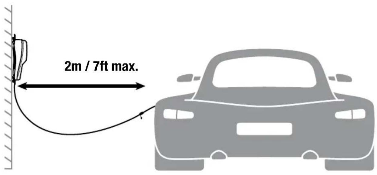
text_image
2m / 7ft max.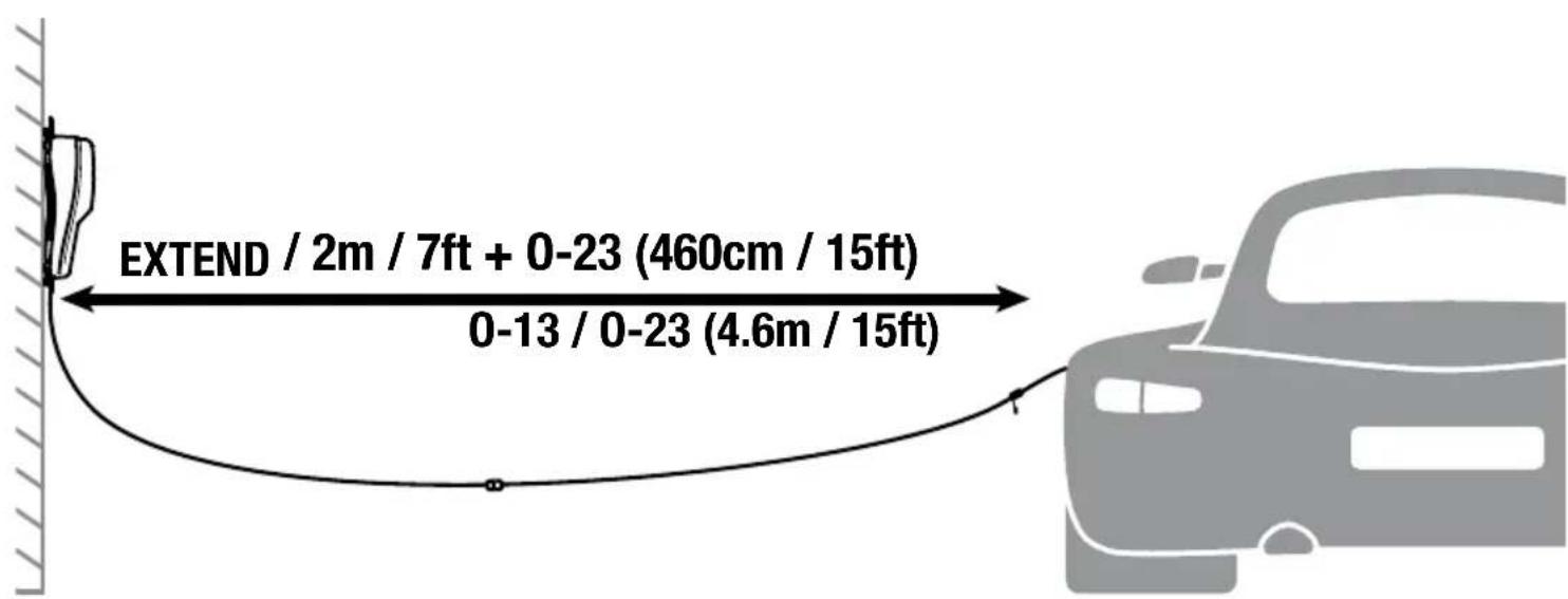
text_image
EXTEND / 2m / 7ft + 0-23 (460cm / 15ft) 0-13 / 0-23 (4.6m / 15ft)
text_image
CHARGEDiscover our full range of accessories at optimize1.com