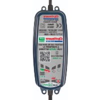
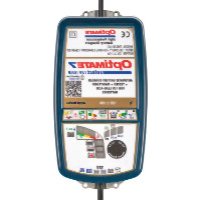
3 + - Battery charger Optimate - Free user manual and instructions
Find the device manual for free 3 + Optimate in PDF.


User questions about 3 + Optimate
0 question about this device. Answer the ones you know or ask your own.
Ask a new question about this device
Download the instructions for your Battery charger in PDF format for free! Find your manual 3 + - Optimate and take your electronic device back in hand. On this page are published all the documents necessary for the use of your device. 3 + by Optimate.
USER MANUAL 3 + Optimate
Automatic charger for 12V lead/acid batteries
IMPORTANT: Read completely
before charging
MODE D'EMPLOI
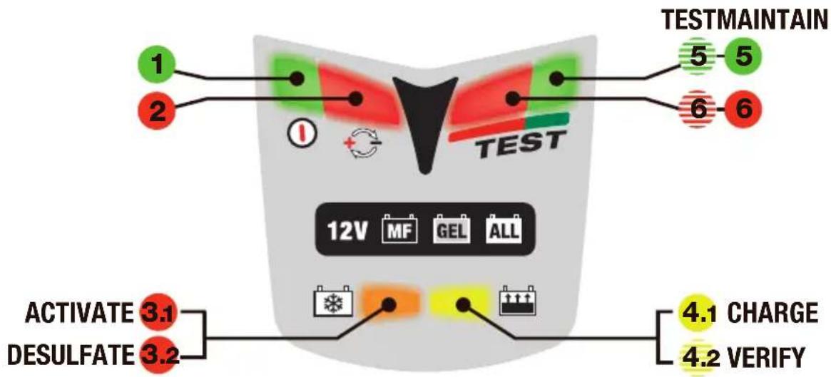
Full details on any LED or step can be found in the manual under the same #
text_image
TESTMAINTAIN 1 2 TEST 5 5 6 6 12V MF GEL ALL ACTIVATE 3.1 DESULFATE 3.2 4.1 CHARGE 4.2 VERIFY- LED #1 - Power on. This LED confi rms AC power supply to the charger.
- LED #2 indicates inverse polarity - wrong output connections. Swap around to activate output.
- Circuit activation and recovery of deep-discharged, neglected batteries
3.1 ACTIVATION - If the battery voltage is above 2V, LED #3 lights briefly to confirm circuit activation. For most batteries LED #3 goes out immediately and charge LED #4 comes on.
3.2 RECOVERY - For neglected or very flat batteries, LED #3 remains on and indicates steadily. If step 3 has not concluded after 2 hours, step 4 engages automatically.
4. Charge and charge verification
4.1 CHARGE: A steady LED #4 indicates the bulk charge stage.
4.2 VERIFICATION: LED #4 fl ashes while the circuit verifies battery charge level.
If the battery requires further charging the programme reverts to CHARGE. Multiple reversions may occur.
These reversions will cause LED #4 to alternate between steady and fl ashing, irregularly.
When LED #4 has flashed continuously for 30 minutes, step 5 engages and a voltage retention test starts.
5. 6. Voltage retention tests alternating half-hourly with battery maintenance
- For a good battery LED #5 fl ashes throughout the 30 minute test. NO CHARGE CURRENT.
- If the battery voltage falls below 12,4V during the test LED #6 (red) willcome on & indicate steadily.
Read § 6 in the main manual if LED #6 indicate in this period.
Maintenance - fl oat charge at a safe voltage limit to counter self-discharge.
Each test period is followed by a 30 minute maintenance charge period. Whichever LED (#5 fl ashing or #6 steady) was indicating at the end of the TEST now indicates steadily. The battery can draw current as required to support small loads & counter self-discharge.
Maintenance and voltage retention test periods continue alternating half-hourly until the battery is disconnected. The test result is updated during each subsequent test.
AUTOMATIC CHARGER FOR 12V LEAD/ACID BATTERIES.
Recommended for batteries of from 2 to 35Ah capacity. Do not use for NiCd, NiMH, Li-Ion or non-rechargeable batteries. Input: 220-240V\~0,075A. Output: 0,6A 9W (max).
IMPORTANT: READ THE FOLLOWING FULL INSTRUCTIONS FOR USE BEFORE USING THE CHARGER.
SAFETY WARNING AND NOTES: Batteries emit EXPLOSIVE GASES - prevent flame or sparks near batteries.
Disconnect AC power supply before making or breaking DC/battery connections. Battery acid is highly corrosive. Wear protective clothing and eyewear and avoid contact. In case of accidental contact, wash immediately with soap and water. Check that the battery posts are not loose; if so, have the battery professionally assessed. If the battery posts are corroded, clean with a copper wire brush; if greasy or dirty clean with a rag damped in detergent. Use the charger only if the input and output leads and connectors are in good, undamaged condition. If the input cable is damaged, it is essential to have it replaced without delay by the manufacturer, his authorised service agent or a qualified workshop, to avoid danger. Protect your charger from acid and acid fumes and from damp and humid conditions both during use and in storage. Damage resulting from corrosion, oxidation or internal electrical short-circuiting is not covered by warranty. Distance the charger from the battery during charging to avoid contamination by or exposure to acid or acidic vapours. If using it in the horizontal orientation, place the charger on a hard, flat surface, but NOT on plastic, textile or leather. Otherwise use the fixing holes provided in the enclosure base to attach the charger to any convenient, sound vertical surface.
EXPOSURE TO LIQUIDS: When placed on a horizontal flat surface this charger is designed to withstand exposure to liquids accidentally spilled or splashed onto the casing from above, or to light rainfall. Do not allow liquid to accumulate below or around the base of the charger. Prolonged exposure to falling rain is inadvisable and longer service life will be obtained by minimizing such exposure. Failure of the charger due to oxidation resulting from the eventual penetration of liquid into the electronic components is not covered by warranty. Never expose connectors or plugs to rain or snow.
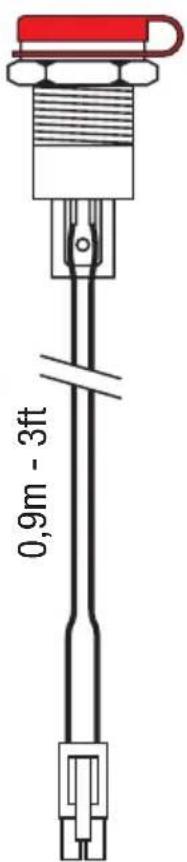
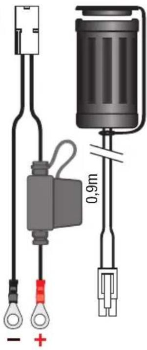
BATTERY CONNECTIONS: 2 sets of interchangeable connection sets are supplied to connect the battery to the charger. One has crocodile clamps for charging the battery off-vehicle, the other has metal eyelets intended for permanent connection to the battery posts, and a resealable rubber protective cap on the 2-pole connector at its other extremity. When fixed permanently to the vehicle's battery, this connection set allows easy and sure connection of the charger to maintain the battery on-vehicle. The resealable rubber cap should be closed whenever the charger is disconnected and/or the vehicle is in use so as to protect the 2-pole connector from dirt and damp. Consult a professional service agent for assistance in attaching the metal eyelets to the battery posts. Distance the polarised two-pole connector (for connection to the charger) as far as possible from the battery and secure it so that it cannot foul any moving part of the vehicle or be pinched or damaged by sharp edges. The in-line fuse in the eyelets connection set protects the battery against such accidental shorting across positive and negative conductors. Replace any burnt fuse only with a similar new fuse of identical type and 7,5A rating.
IMPORTANT NOTES:
-
When charging a car battery, or if using the battery clamps, fi rst disconnect and remove the battery from the vehicle and place it in a well ventilated area.
-
If the battery is deeply discharged (and possibly sulphated), it is essential to disconnect the battery from the vehicle before connecting the charger for a recovery attempt. The charger's special recovery mode cannot engage if it senses that the battery is still connected to a vehicle wiring circuit which effectively offers a lower electrical resistance than the battery on its own. However, if the deep-discharged battery is not removed for recovery, neither battery nor vehicle electronics will be damaged.
-
If nonetheless you intend to connect the charger to an automotive battery using the battery clips connection set without fi rst disconnecting and removing the battery, connect fi rst to the battery terminal not connected to the chassis, then the other battery clip to the chassis well away from the battery and fuel line. Do this before connecting to the AC input. Always disconnect in reverse sequence.
USING THE OPTIMATE™3+
The clauses below are numbered the same as the quick guide on the inside front cover.
1. and 2. Connections and input power
Connect the charger to the battery: RED clamp to POSITIVE (POS, P, +) terminal and BLACK clamp to NEGATIVE (NEG, N,−) terminal. Now you are ready to start:
- Connect the charger to a mains supply socket providing AC supply of 220 to 240V. The "POWER ON" LED #1 should illuminate. If not, check your AC supply and the connection to it.
- If the INVERSE POLARITY LED #2 indicates, the battery connections are incorrect. The charger is electronically protected so no damage will result, and the output will be disabled automatically. Disconnect the AC input, swap the battery connections around, then restore the AC input power.
3. Circuit activation and recovery of deep-discharged, neglected batteries
For safety reasons, the OptiMate™ output will only switch on if a battery retaining at least 2V is correctly connected to it and to a live 220-240V input. If these conditions are not met, only the POWER ON LED #1 will light on the LED panel.
3.1 Immediately the output circuit is activated, the orange DESULFATE LED #3 comes on very briefly while the OptiMate™ checks whether the battery can be charged effectively by the normal multi-stage programme. If it can, the yellow CHARGE LED #4 will almost immediately replace the DESULFATE LED.
3.2 If the battery is extremely flat (deep-discharged or sulphated), the DESULFATE LED will continue to indicate for up to 2 hours while a special high voltage is applied to force a very small fixed current into the battery in a recovery attempt. The charge voltage is limited at a maximum 20V while the circuit attempts to deliver a current of 200mA into the battery. This can continue for up to 2 hours maximum, or until the moment when the automatic circuit judges that the battery can accept the normal charging programme. At this moment or in any case after the maximum time limit of 2 hours has elapsed, the CHARGE mode ( § 4 ) will engage.
NOTE: A battery left deep-discharged for an extended period may develop permanent damage in one or more cells. Such batteries may heat up excessively during charging. Stop charging any battery immediately if it is uncomfortably hot to touch.
4. Charge and charge verification
4.1 The BULK CHARGE stage (steady LED #4) delivers a constant current of about 0,6 Amps into the battery. This will cause the charging voltage to increase gradually. When it reaches 14,3V, the OptiMate™ will start the absorption and CHARGE VERIFICATION stage.
4.2 CHARGE VERIFICATION (flashing LED #4): The charging voltage is now limited at 13,6V during 30 minutes whilst the battery's charge level is verified. If the battery requires further charging the programme will revert to the main CHARGING stage ( § 4.1 ) and yellow LED #4 will indicate steadily again. When the rising voltage again signals that the battery is approaching full charge the circuit reverts to VERIFICATION and LED #4 resumes fl ashing. These reversions may occur as many times as is necessary to reduce the battery's current demand below 200mA at 13,6V (which is consistent with a battery that has accepted as much charge as its basic condition allows). As soon as the circuit has verified that the charge is adequate (signaled by LED #4 having fl ashed continuously and consistently for a full 30 minutes), the voltage retention test (see § 5 ) automatically follows.
NOTE Some sealed “MF” or “AGM” batteries that have been neglected may cause the programme to advance to the CHARGE VERIFICATION stage (4.2) without proceeding through the bulk CHARGE stage ( § 4.1 ). The built-in diagnostics will detect and correct this anomaly. The circuit will oscillate between bulk charge and verification as described in § 4.2 .
5. and 6.
Voltage retention tests alternating half-hourly with battery maintenance
The first VOLTAGE RETENTION TEST period of 30 minutes follows § 4.2, thereafter a 30 minute MAINTENANCE period. These 30 minute TEST and MAINTENANCE periods then alternate for as long as the battery remains connected. Delivery of current to the battery is interrupted for 30 minutes during voltage retention test periods to allow the battery to rest (thereby minimizing loss of water from the electrolyte) and to allow the circuit to monitor the battery's voltage decline to determine its ability to retain charge and deliver power.
- For batteries with a good state of health the green LED #5 should flash at the start of the test period and continue to flash for the full 30 minutes until the next 30 minute maintenance period commences, when the LED indication reverts to steady.
- If the battery remains in circuit with the vehicle's electrical system, and accessories or lights impose an electrical load on the battery, the green LED may give way to a steady red LED indication. Remove the battery from the vehicle and reconnect the OptiMate. The charge programme will in due course again arrive at a voltage retention test result. If the LED indication is again red, read the following note.
NOTE ON RED LED INDICATION #6: If the above test on a battery removed from the vehicle results in a red LED indication, you are advised to take the battery to a professional service workshop equipped with a BatteryMate™ motorcycle battery tester-charger (www.batterymate.com) or a TestMate™ digital battery tester (www.testmate.com), for a more thorough investigation. The red LED means that after being charged the battery's voltage is not being sustained or that despite recovery attempts the battery was irrecoverable. This may be due to a defect in the battery itself, such as a short-circuited cell or total sulphation, or, in the case of a battery still connected to the vehicle's wiring system, the red LED #6 may be signalling a loss of current through deteriorated wiring or a degraded switch or contact, or in-circuit current-consuming accessories. A sudden load such as the headlights being switched on while the charger is connected can also cause the battery voltage to dip signifi cantly. Always remove the battery from the vehicle, reconnect the OptiMate™ and allow it to proceed through its programme once more.
FINAL NOTE ON THE VOLTAGE RETENTION TEST: This test is a strongly indicative but not necessarily a conclusive test of battery condition, which can be more precisely established by using a TestMate™mini which tests 12V batteries on the vehicle during cranking, as well as the charging system operation. Alternatively, contact a workshop as advised above.
Automatic battery maintenance
The 30 minute fl oat charge maintenance periods follow and alternate with the 30 minute test periods during which there is no charge current. This “50% duty cycle” prevents loss of electrolyte in sealed batteries and minimizes gradual loss of water from the electrolyte in batteries with fl ller caps, and thereby contributes signifi cantly to optimizing the service life of irregularly or seasonally used batteries. The circuit offers current to the battery within a safe 13,6V voltage limit (“fl oat charge”), allowing it to draw whatever small current is necessary to sustain it at (or close to) full charge and compensate for any small electrical loads imposed by vehicle accessories or on-board computer, or the natural gradual self-discharge of the battery itself.
NOTE: Maintaining a battery for extended periods: After activating the charger you should observe the LED indications every few hours until the test result is displayed. If at any time the battery is hot to touch, disconnect it from the charger and get it professionally tested using a BatteryMate™ or TestMate™ II electronic tester specifically designed for that type of battery. At least once every two weeks, check that the connections between the charger and battery are secure, and, in the case of batteries with filler caps on each cell, disconnect the battery from the charger, check the level of the electrolyte and if necessary, top up the cells (with distilled water, NOT acid), then reconnect. When handling batteries or in their vicinity, always take care to observe the SAFETY WARNINGS above.
Charging time
The time required for the OptiMate™ 3+ to complete a charge on a fl at but not severely discharged and otherwise undamaged battery is roughly equal to the battery's Ah rating, so a 12Ah battery should take no more than about 12 hours to progress to the self-discharge check (§ 5). Deep-discharged batteries may take signifi cantly longer.
NOTE: The total charging time of the above steps 4.1 and 4.2 is not limited.
If using the OptiMate™3+ on a severely discharged automobile battery of larger capacity than the recommended rated capacity range (2 to 35Ah), a full charge may require up to several days. In such cases, prolonged continuous charger operation at maximum output and in warm ambient temperatures may cause the charger to become quite hot. For best charger servie life, it is recommended that you switch off and allow the charger to cool thoroughly to room temperature before reconnecting it to complete the charge.
Disconnection
Disconnect the OptiMate ^™ fi rst from the AC mains supply and then from the battery. Always disconnect from the AC mains before reconnecting to the same or another battery. Close the rubber cap on the eyelets connection lead (TM-71) if this is attached to the battery, to protect its 2-pole connector against dirt and damp while the OptiMate ^™ is disconnected.
LIMITED WARRANTY
TecMate (International) SA, Sint-Truidensesteenweg 252, B-3300 Tienen, Belgium, makes this limited warranty to the original purchaser at retail of this product. This limited warranty is not transferable. TecMate (International) warrants this battery charger for two years from date of purchase at retail against defective material or workmanship. If such should occur the unit will be repaired or replaced at the option of the manufacturer. It is the obligation of the purchaser to forward the unit together with proof of purchase, transportation or mailing costs prepaid, to the manufacturer or its authorized representative. This limited warranty is void if the product is misused, subjected to careless handling, or repaired by anyone other than the factory or its authorized representative. The manufacturer makes no warranty other than this limited warranty and expressly excludes any implied warranty including any warranty for consequential damages.
THIS IS THE ONLY EXPRESS LIMITED WARRANTY AND THE MANUFACTURER NEITHER ASSUMES NOR AUTHORIZES ANYONE TO ASSUME OR MAKE ANY OTHER OBLIGATION TOWARDS THE PRODUCT OTHER THAN THIS EXPRESS LIMITED WARRANTY. YOUR STATUTORY RIGHTS ARE NOT AFFECTED.
GUIDE RAPIDE – PANNEAU D'INFORMATION LED
SNELGIDS – LED INFORMATIE PANEEL
SNABBGUIDE – INFORMATIONSPANEL (LYSDIOD)
Tests battery voltage, cranking power and charging system operation of 12V batteries – without disassembly.
natural_image
Diagram of three automotive electrical connectors with terminal labels and terminal connections (no readable text or symbols)TM-78 TM-68
text_image
0,9m - 3ftTM-73
text_image
- + 0,9mTM-77

text_image
2,5m - 8ft
natural_image
Pure electrical connector diagram without any text or symbols