AirJet Hybrid - Cooker Klarstein - Free user manual and instructions
Find the device manual for free AirJet Hybrid Klarstein in PDF.


User questions about AirJet Hybrid Klarstein
0 question about this device. Answer the ones you know or ask your own.
Ask a new question about this device
Download the instructions for your Cooker in PDF format for free! Find your manual AirJet Hybrid - Klarstein and take your electronic device back in hand. On this page are published all the documents necessary for the use of your device. AirJet Hybrid by Klarstein.
USER MANUAL AirJet Hybrid Klarstein
Extractor hood and induction hob
text_image
COOKINGCO COOKINGCOO KINGCOOKING KINGCOOKING COOKINGCOO KINGCOOKING KINGCOOKING KINGCOOKINGKLARSTEIN
www.klarstein.com
text_image
QR code image containing encoded data, no visible human-readable textINHALTSVERZEICHNIS
text_image
Exploded view diagram of household air conditioner components with numbered parts and directional arrowstext_image
MIN 220 ≥100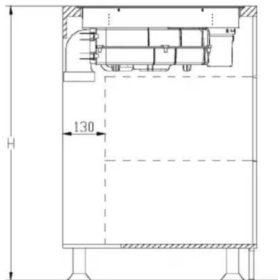
text_image
H 130natural_image
Technical line drawings of a rectangular box with an inset showing its cross-section and side view (no text or symbols)natural_image
Simple line drawing of a rectangular box and a stacked container with an upward arrow (no text or symbols)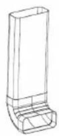
natural_image
Technical line drawing of a mechanical component with a circular end and a handle (no text or symbols)natural_image
Technical schematic of a mechanical or fluid system with directional arrows and dimension lines (no text or symbols)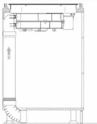
natural_image
Architectural cross-section diagram of a building interior with stairs and structural elements (no text or labels)4
text_image
Bnatural_image
Architectural floor plan showing room layout with furniture and a directional arrow (no text or labels)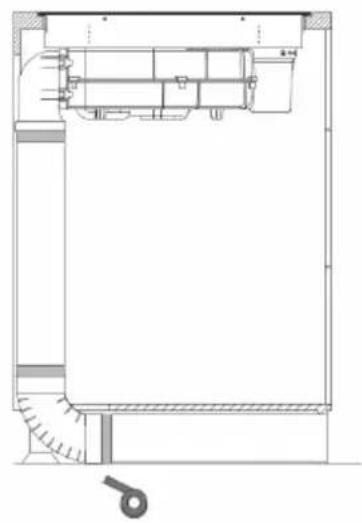
natural_image
Architectural cross-section diagram of a building facade with internal components and structural details (no text or labels)6
natural_image
Technical drawing of a mechanical joint or bracket assembly with hatched areas and a central arrow indicating direction (no text or symbols)natural_image
Technical line drawing of a rectangular object with an upward arrow indicating growth or assembly (no text or symbols)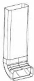
natural_image
Technical line drawing of a mechanical component with a bracket and handle (no text or symbols)natural_image
Technical schematic of a mechanical or fluidic device with internal components and directional arrows indicating flow or movement (no text or symbols present)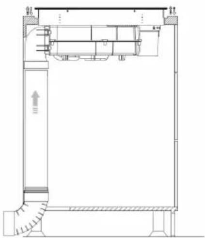
natural_image
Architectural cross-section diagram of a building facade with internal components and structural elements (no text or labels)4
natural_image
Architectural cross-section diagram of a room with furniture and a handle (no text or labels)5
natural_image
Technical drawing of a mechanical joint or bracket with hatched areas and an arrow indicating direction (no text or symbols)natural_image
Technical line drawing of a mechanical assembly with no visible text or symbols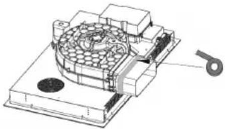
natural_image
Technical illustration of a mechanical assembly with a circular component and a separate part labeled '5' (no text or symbols present)4
natural_image
Technical line drawing of a mechanical assembly mounted on a brick wall, showing structural components and alignment (no text or symbols)
text_image
X 205
natural_image
Technical drawing of a mechanical joint or bracket with hatched areas and a central screw (no text or symbols)| Netzkabel H07RN-F 5G2,5mm2 | ||
| L1: BK N1: GY N3: GN/YE | ||
| L2: BN N2: BU | ||
| L2 = Phase, N2 = Neutralleiter, PE = Erdung | ||
text_image
Diagram showing two hand positions with checkmark and cross symbols, likely indicating correct and incorrect states.natural_image
Three identical cooking pots with crossed-out X symbols, placed on a flat surface (no text or labels)natural_image
Four identical cooking pots with crossed-out X marks, shown in different orientations (no text or symbols)natural_image
Technical line drawing of a mechanical assembly with a central opening and surrounding components (no text or symbols)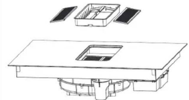
natural_image
Technical line drawing of a multi-level electronic device with internal components and mounting base (no text or symbols)PRODUKTDATENBLATT ABZUG
PRODUKTDATENBLATT KOCHFELD
natural_image
Symbol of a trash bin crossed with a diagonal line, no text or numbers presentBerlin Brands Group UK Limited
PO Box 42
272 Kensington High Street
London, W8 6ND
United Kingdom
Dear customer,
Congratulations on your purchase. Please read the following instructions carefully and follow them to prevent potential damage. We accept no liability for damage caused by disregarding the instructions and improper use. Please scan the QR code to access the latest operating instructions and further information about the product.

text_image
QR code image containing encoded data, no visible human-readable textCONTENTS
Safety Instructions for the Extractor Hood 55
Safety Instructions for the Induction Hob 57
Instructions for operating and maintaining the induction hob 58
Device Overview 61
Before and after installation 63
Dimensions of the required recess in the worktop 65
General installation of the cooker hood 67
Installation of the exhaust pipe for recirculation mode 68
Installation of the bent exhaust pipe for exhaust operation 71
Installation of the bent exhaust pipe for exhaust operation 73
Electrical connection 76
Operation of the hob and extractor hood 77
Cooking tips 85
Cleaning and care of the hob 87
Cleaning and care of the extractor hood 89
Troubleshooting 91
Error notifications 96
Product data sheet extractor 98
Product data sheet hob 99
Notes on environmental protection 100
Disposal considerations 100
Manufacturer & importer (UK) 100
TECHNICAL DATA
| Article number | 10046661, 10046662, 10046663, 10046664 |
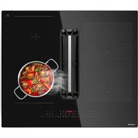
| Device description | Induction glass ceramic hob with 4 cooking zones and built-in extractor hood |
| Voltage 220-240 V | |
| Frequency 50/60 Hz | |
| Maximum power consumption 7.2 kW | |
| Fuse/power supply 2 x 16 A | |
| Dimensions (W x D x H) | |
| 10046663 | 830 x 515 x 200 mm |
| 10046664 | 900 x 515 x 200 mm |
| 10046661, 10046662 | 600 x 515 x 260 mm |
| 720 x 515 x 260 mm | |
| Surface material Glass ceramic | |
| Power levels 1 - 8, b | |
| Dimensions of the rear cooking zone 175 x 195 mm | |
| Dimensions of the front cooking zone 175 x 195 mm | |
| Power of the front cooking zone 2500 W | |
| Power of the rear cooking zone 2500 W | |
| Max. power for 2 cooking zones working together on the same side | 3600 W |
| Maximum static pressure of the extractor hood | 600 pa |
| Power levels of the extractor hood 1 - 7, | 8, b |
| Extractor hood air outlet 310 x 180 mm | |
| Filter Yes | |
| Filter surface 2 x 0.2 m | 2 |
| Max. filter life 150 hours / 1 year |
SAFETY INSTRUCTIONS FOR THE EXTRACTOR HOOD
- Read all instructions carefully before use and keep this user manual in a safe place for future reference.
- The installation work may only be carried out by an electrician or a qualified person. Before using the cooker hood, make sure that the voltage (V) and frequency (Hz) indicated on the cooker hood correspond to the voltage and frequency of the power supply in your household.
- We accept no liability for damage caused by improper use or installation.
• Children under 8 years of age must not use the cooker hood. - The appliance is intended for use in the home and similar environments only. It is not intended for commercial use.
- Clean the appliance and the filter regularly to keep the appliance working efficiently.
• Always disconnect the power plug from the socket before cleaning. - Clean the appliance exactly as indicated in the operating instructions.
- Do not use an open fire under the extractor hood.
- If the unit is not functioning normally, contact the manufacturer or a specialist company.
- Children from the age of 8 years and mentally, sensory and physically impaired persons may only use the device if they have been informed in detail about the functions and safety precautions by a supervisor responsible for them beforehand and understand the associated risks.
- If the power cord is damaged, it must be replaced by the manufacturer, an authorised specialist company or a similarly qualified person.
- If the cooker hood is used with cookers that burn gas or other fuels, there must be adequate ventilation in the room.
- Do not flambé under the extractor hood.
- Caution: The surface of the unit may become hot during operation.
Important instructions for installation
- The air must not be discharged into a flue used for extracting flue gases from gas or other fuels (does not apply to appliances that only return the air to the room).
- Observe all regional regulations for the installation of ventilation systems.
Important notes on exhaust air operation
WARNING
Danger of poisoning from recirculated exhaust gases! Do not operate the appliance in extract air mode if it is operated together with a room air-dependent fireplace and sufficient air circulation is not guaranteed.
Room air-dependent fireplaces such as gas, oil, wood or coal heaters, boilers or instantaneous water heaters draw the air from the room and lead it outdoors through an exhaust pipe or chimney. In extract air mode, air is extracted from the kitchen and neighbouring rooms. Without sufficient supply air, negative pressure is created. Toxic gases from the chimney or exhaust pipe can be sucked back into the living rooms.
- Make sure that sufficient fresh air supply is guaranteed and that the air can circulate.
- A supply air/exhaust air wall box is not sufficient to ensure compliance with the limit value.
Safe operation is only possible if the negative pressure at the location of the fireplace does not exceed 4 Pa (0.04 mbar). This can be achieved if the air required for combustion can flow in through non-closable openings in doors and windows in conjunction with a supply air / exhaust air wall box. In any case, have a professional chimney sweep advise you and assess the entire ventilation system of the house. If necessary, they can tell you the necessary measure for ventilation.
If the cooker hood is used exclusively in recirculation mode, operation is possible without restriction.
Important note on dismantling the unit
- Disassembly is the same as installation/assembly in reverse order.
- Have a second person help you during disassembly to avoid injury.
SAFETY INSTRUCTIONS FOR THE INDUCTION HOB
Risk of electrocution
- Unplug the device from the power outlet before servicing or repairing the device.
- Connection to a grounded electrical outlet is required and mandatory.
- Changes to the power connection may only be carried out by a qualified electrician.
- Failure to follow the instructions may result in electric shock or death.

CAUTION
Risk of injury! The edges of the hotplate are sharp. Take care, otherwise you could injure yourself with cuts.
General Safety Instructions
- Read these operating instructions carefully before installing and/or using the unit.
- Never place easily combustible materials or products on the hob.
- Please provide this information to the person who installs the unit, as this may save installation costs.
- This appliance must be installed in accordance with these operating instructions to prevent damage to property and personal injury.
- This appliance must be installed and earthed by a qualified person.
- This unit should be connected to a circuit that has a circuit breaker that allows complete disconnection from the power supply.
- Incorrect installation of the unit may invalidate all guarantee and warranty claims.
- Children over 8 years as well as mentally, sensory and physically impaired persons may only use the device if they have been informed in detail about the functions and safety precautions by a supervisor responsible for them beforehand and understand the associated risks.
- The appliance is not a toy. Cleaning and maintenance of the hob should never be carried out by children alone.
-
If the mains cable is damaged, it must be replaced by the manufacturer, customer service or a similarly qualified person in order to avoid damage to property and/or personal injury.
-
To reduce the risk of electric shock, switch off the appliance immediately if the surface (hob surface made of glass ceramic or similar material that protects live parts) is cracked.
- Do not place metal objects such as knives, forks, spoons and pot lids on the hob as they could become very hot there.
- Do not use a steam cleaner to clean the hob.
- The unit must not be used in connection with an external timer or a separate remote control system.
- The cooking process must be supervised. A short cooking process must be permanently supervised.
- Never leave the appliance unattended while cooking, as cooking with oil or fat in particular can be dangerous and cause a fire to break out. Never try to extinguish a grease fire with water! Instead, turn off the appliance and cover the flame with a fire blanket or pot lid.

WARNING
Risk of fire! Do not place any objects other than pots and pans on the induction hobs.
INSTRUCTIONS FOR OPERATING AND MAINTAINING THE INDUCTION HOB
Risk of electrocution
- Never cook on a broken or cracked cooking surface. If the cooking surface breaks or cracks, switch off the appliance immediately, disconnect the mains plug from the socket and contact a qualified technician.
- Switch off and unplug the induction hob before cleaning and maintenance.
- Failure to follow the instructions may result in electric shock or death.
Health risks
- This unit complies with electromagnetic safety standards.
- People with pacemakers or other electrical implants (such as insulin pumps) must contact their doctor or implant manufacturer before using the appliance to ensure that their implants are not affected by the electromagnetic field of the hotplate.
- Failure to follow the instructions may result in death.
CAUTION
Risk of burns! During use, the parts of the appliance accessible to the user become so hot that they can cause burns. Make sure that your body, clothing and any materials other than cooking utensils do not touch the hotplate until it has cooled down completely.
- Keep children away from the induction hob.
- Pot handles can become so hot during use that you should not touch them. Make sure that the pot handles are not directly above hobs that are switched on. Make sure that the pot handles are out of reach of children.
- Failure to follow the instructions may result in burns and scalds.

WARNING
Risk of injury! The razor-sharp blade of a hob scraper is exposed as soon as you remove the safety cover. Exercise extreme caution when using. Always store the hob scraper with the safety cover on, out of the reach of children. Failure to follow the instructions may result in injuries and cuts.
General Safety Instructions
- Never leave the device unattended while in use. Overcooking can cause smoke to develop and splashes of fat could ignite.
- Do not store any objects on the device.
- Never leave objects or other utensils on the unit.
- Do not place any magnetisable objects (e.g. credit cards, memory cards) or electronic devices (e.g. computers, MP3 players) near the unit as they could be affected by the electromagnetic field.
- Never use the appliance to warm up or to heat the room.
- Switch off the hobs and the cooking surface after use as described in these operating instructions (e.g. by using the touch control). Do not rely on the pot detection function to switch off the device when you remove the pots.
-
Do not allow children to play with, sit on, stand on or climb on the device.
-
In the interest of children, do not store anything in the cupboards above the device. Children who secretly climb onto the unit could be seriously injured by falling objects.
- Children or persons with reduced mental capacity should be instructed in the use of the appliance by a person responsible for them to ensure that they can use the appliance without endangering themselves or others.
- Do not repair or replace any parts of the appliance unless this is explicitly recommended in the operating instructions. All other repair and maintenance work should be carried out by a qualified electrician.
- Do not drop or place heavy objects on the cooking surface.
- Do not stand on the cooking surface.
- Do not use pots with sharp edges and do not drag them over the glass surface as this could scratch it.
- Do not use metal brushes or other aggressive cleaning agents to clean the surface, as this could scratch it.
- This appliance is intended for use in households and similar environments only, such as staff kitchens in shops, offices and other work environments, in farmhouses, by guests in hotels, motels and bed & breakfasts.
- Never touch the hobs with your bare hands during use.
- Children under the age of 8 should not be able to get near the appliance.
DEVICE OVERVIEW
Extractor hood components
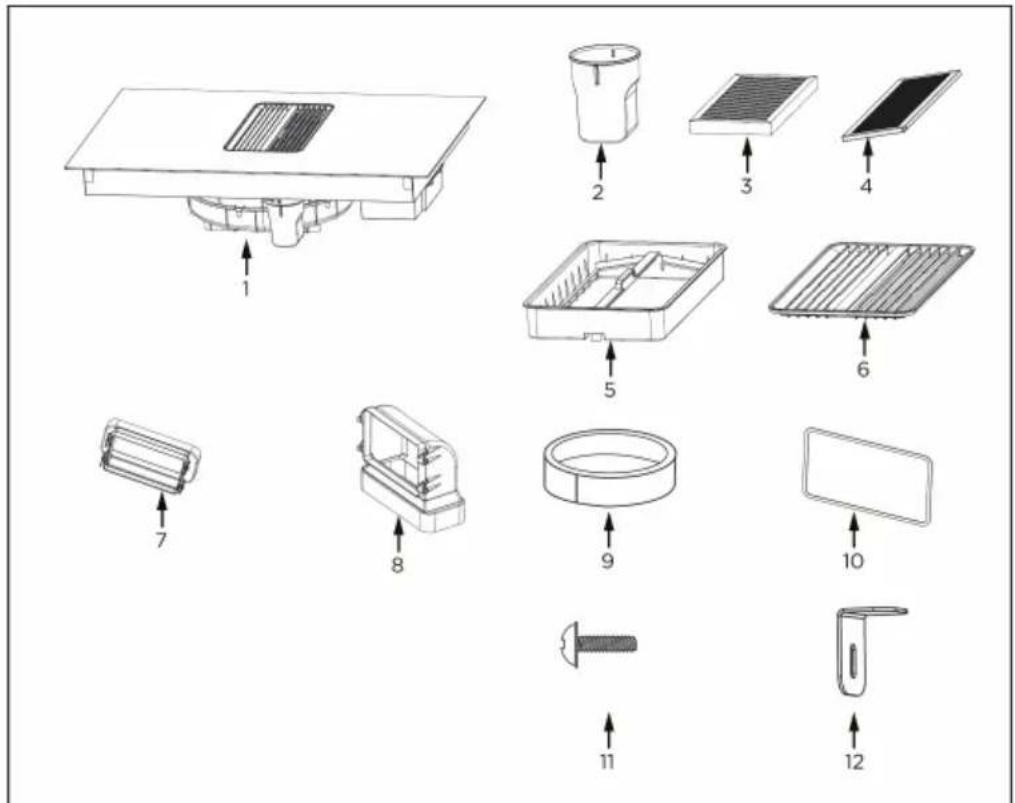
text_image
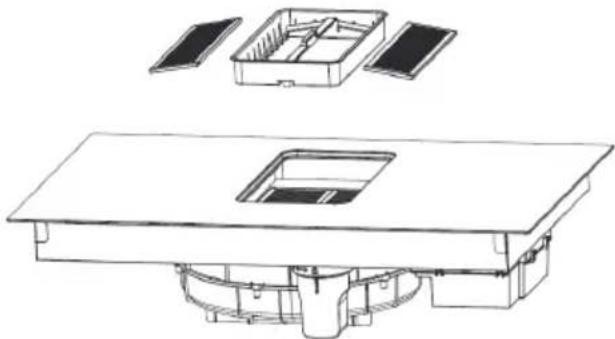
Exploded view diagram of household air conditioner components with numbered parts and directional arrows| Number Designation Number of | pieces |
| 1 The main body 1 | |
| 2 Cup 1 | |
| 3 Grease filter 2 | |
| 4 Activated carbon filter 2 | |
| 5 Filter holder 1 | |
| 6 Grid 1 | |
| 7 Straight adapter 1 | |
| 8 90° adapter 1 | |
| 9 Rubber ring 1 | |
| 10 Sponge strips 1 | |
| 11 Screw M4*10 4 | |
| 12 Mounting bracket 4 |
Hob overview
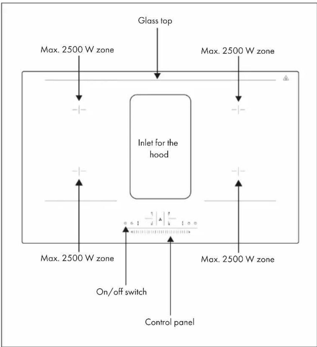
text_image
Glass top Max. 2500 W zone Max. 2500 W zone Inlet for the hood Max. 2500 W zone On/off switch Control panel Max. 2500 W zone Max. 2500 W zoneBEFORE AND AFTER INSTALLATION
Before installation
Check and ensure that:
- the work surface is level and that no components interfere with the space requirements of the unit.
- the work surface is made of heat-resistant and insulating material.
- an oven, when the device is installed above it, has a built-in cooling fan.
- a suitable circuit breaker, which allows complete disconnection from the supply mains, has been integrated and mounted in the standing wiring in accordance with the local wiring regulations.
- the circuit breaker is of approved design and has a contact gap of 3 mm between all poles (or in all active [phase] conductors if local regulations permit).
- the circuit breaker is easily accessible to the user of the induction hob.
- Contact the local building authorities if you have any doubts about the installation.
- Apply heat-resistant and easy-to-clean materials (such as ceramic tiles) to the walls surrounding the induction hob.
After installation
Check and ensure that:
- the mains cable is not accessible through cupboard doors or drawers.
- fresh air access to the underside of the unit is ensured so that air exchange can take place.
- a heat shield is fitted underneath the appliance when the appliance is installed above drawers or cupboards.
- the circuit breaker is easily accessible to the user of the induction hob.
- Make a ventilation hole with a total area of at least 100 cm ^2 in the lower part of the oven to keep the circulation with the outside air, otherwise leaking gas will accumulate and cause an explosion. If an LPG cylinder is used, the distance between the stove and the gas cylinder should be more than 100 cm.
Special Installation Instructions

WARNING
Risk of injury! The induction hob must be installed by qualified personnel or technicians. Never carry out the work yourself.
- The induction hob must be installed by qualified personnel or technicians. Never carry out the work yourself.
- The hob must not be installed directly above a dishwasher, fridge, freezer, washing machine or tumble dryer as the moisture can damage the electronics of the hob.
- The induction hotplate must be installed in such a way that optimal heat radiation is guaranteed.
- The wall and the heating zone above the work surface must be heat resistant.
- To avoid damage, the sandwich layer and the glue must be heat resistant.
Connection of the hob to the mains

WARNING
Risk of injury! Check with an electrician whether the house installation is suitable without changes. Changes may only be made by a qualified electrician. This hob may only be connected to the mains by a suitably qualified person.
Before connecting the hob to the mains, check with the electrician that:
- The domestic installation is suitable for the power consumption of the hob.
- The voltage corresponds to the value indicated on the rating plate.
- The cable sections of the power supply can withstand the load specified on the rating plate.
- No adapters, reducers or branching devices may be used to connect the hob to the mains supply, as they can lead to overheating and the risk of fire.
- The power supply cable must not touch any hot parts and must be laid in such a way that the temperature does not exceed 75^ at any point.
DIMENSIONS OF THE REQUIRED RECESS IN THE WORKTOP
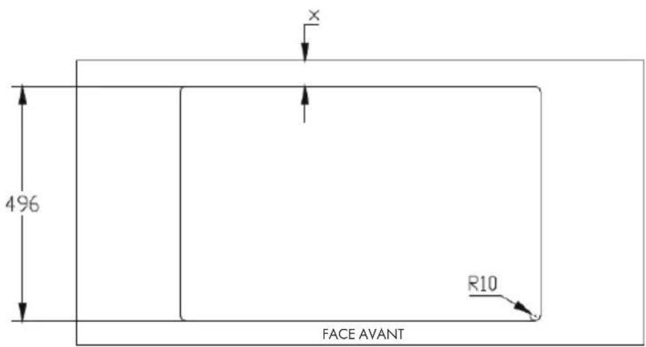
Top flush installation
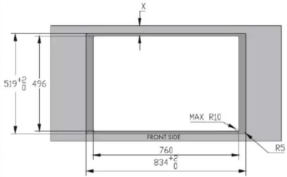
text_image
X 519⁺²₀ 496 MAX R10 FRONT SIDE 760 834⁺²₀ R5Standard installation
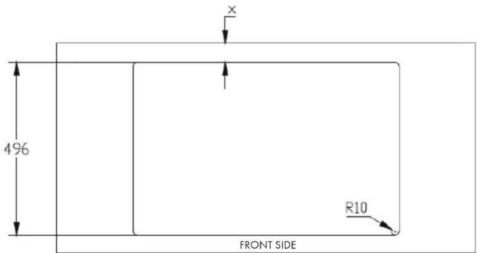
text_image
496 R10 FRONT SIDE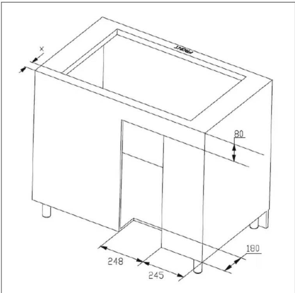
text_image
X 80 248 245 180 FRONT| Table width (Y) X | |
| 600-650 mm 54 mm | |
| ≥ 650 mm 65 mm |
GENERAL INSTALLATION OF THE COOKER HOOD
1
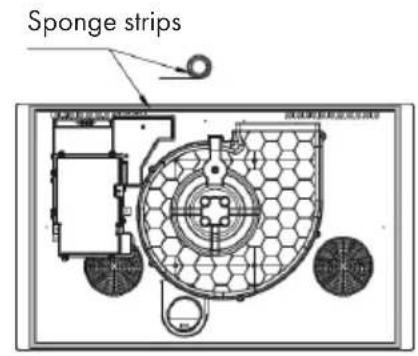
text_image
Sponge strips2
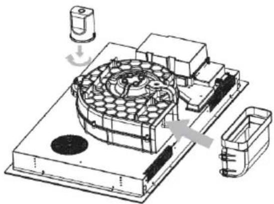
natural_image
Technical illustration of a mechanical assembly with internal components and directional arrows (no text or symbols)Glue on the sponge strip. Install the water cup and 90° adapter
3
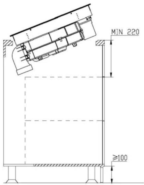
text_image
MIN 220 ≥100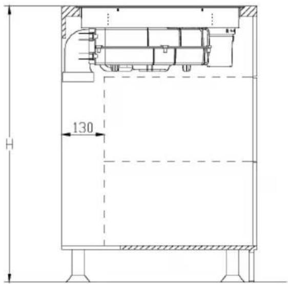
text_image
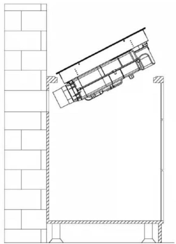
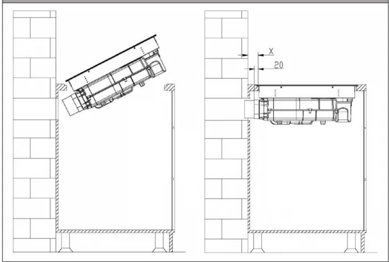
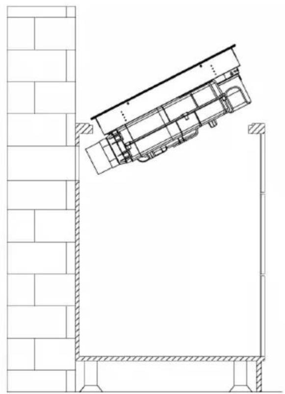
H 130Place the entire unit in the cabinet and adjust the device
INSTALLATION OF THE EXHAUST PIPE FOR RECIRCULATION MODE
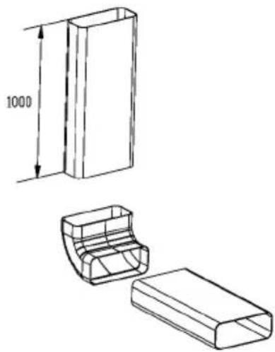
Optional accessories
natural_image
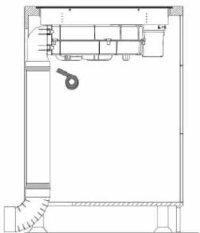
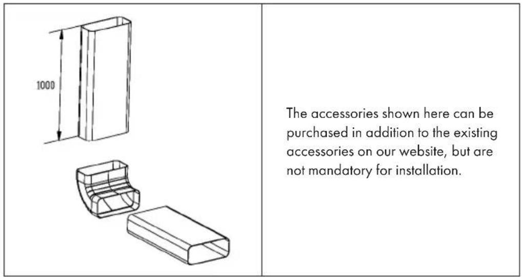
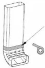
Technical line drawings of a rectangular box with an open lid and side view, showing dimensions (no text or symbols)The accessories shown here can be purchased in addition to the existing accessories on our website, but are not mandatory for installation.
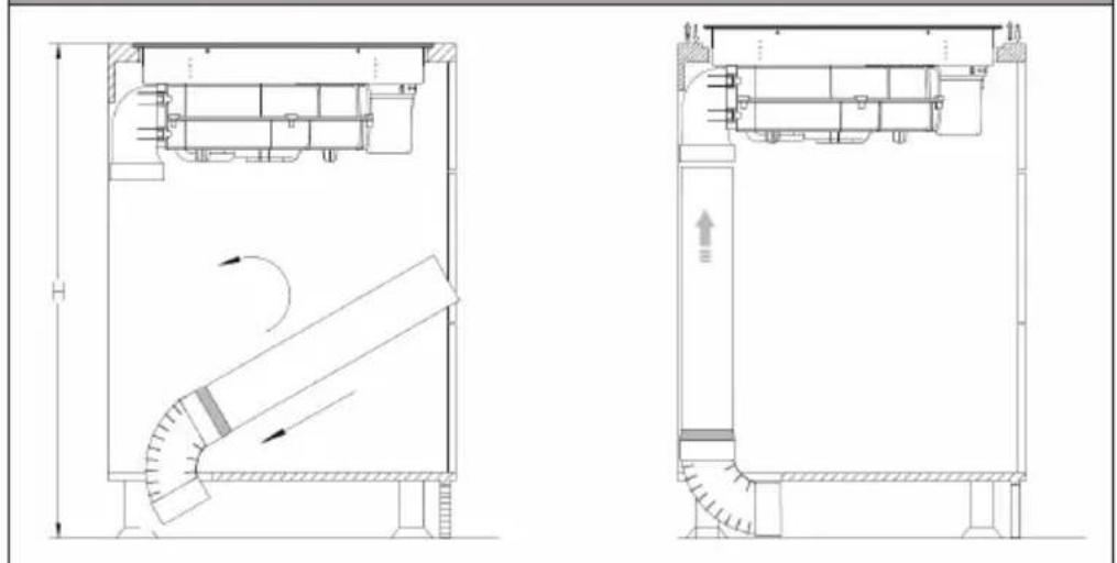
Installation of the exhaust pipe
1
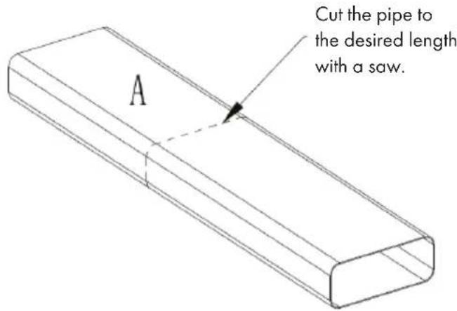
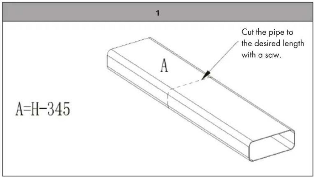
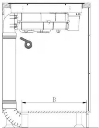
A=H-345
text_image
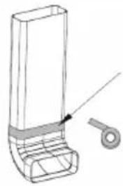
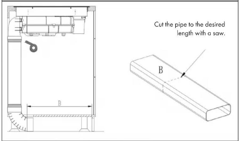
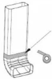
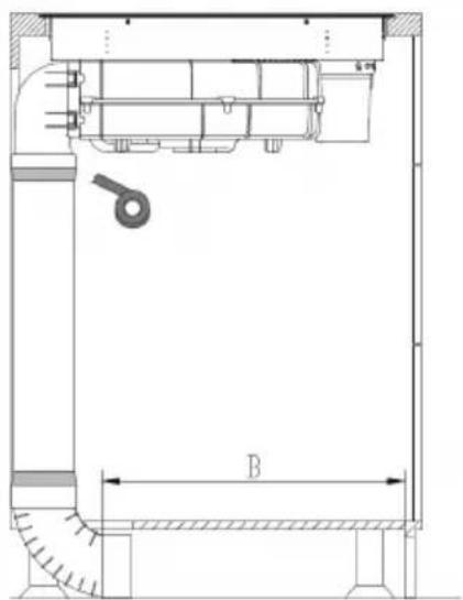
Cut the pipe to the desired length with a saw. A2
text_image
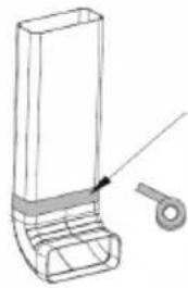
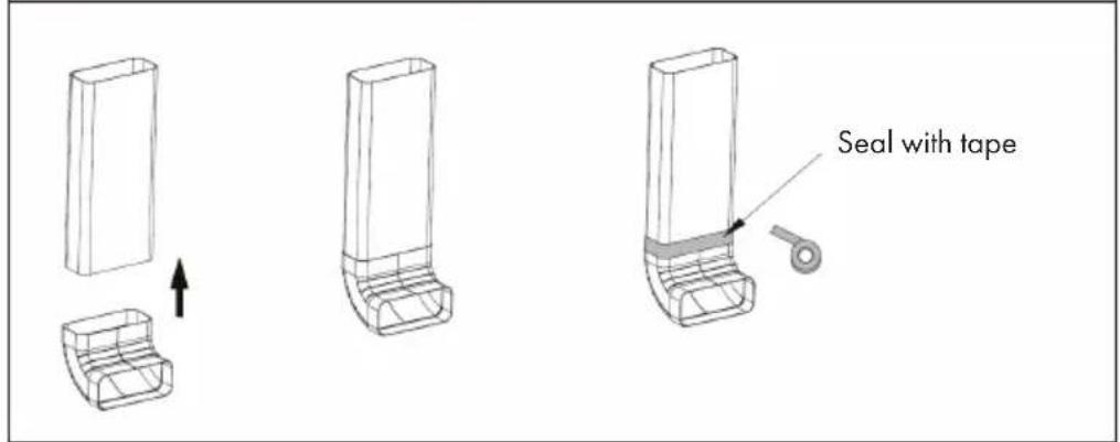
Seal with tape3
natural_image
Technical schematic of a mechanical device with cross-sectional views and internal components (no text or labels)4
text_image
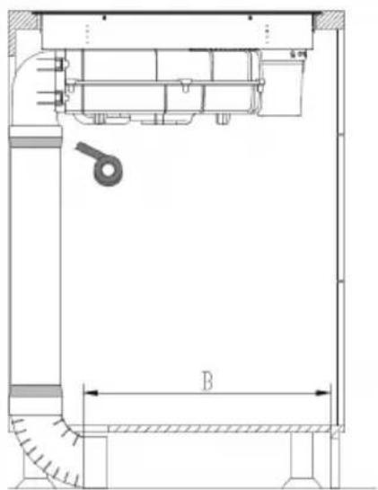
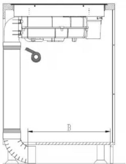
Cut the pipe to the desired length with a saw. BCut the pipe to the desired length with a saw.
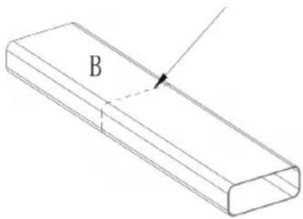
text_image
B5
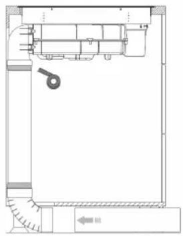
natural_image
Architectural floor plan showing room layout with furniture and a directional arrow (no text or labels)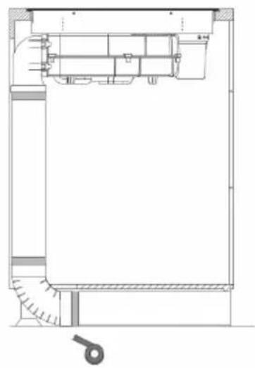
natural_image
Architectural cross-section diagram of a building facade with internal components and structural details (no text or labels)6
natural_image
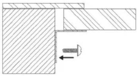
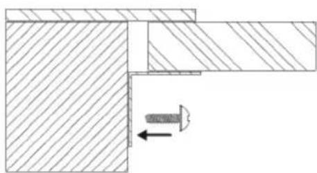
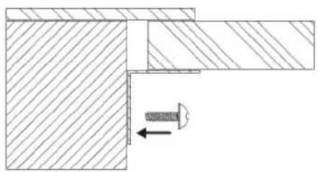
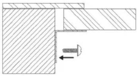
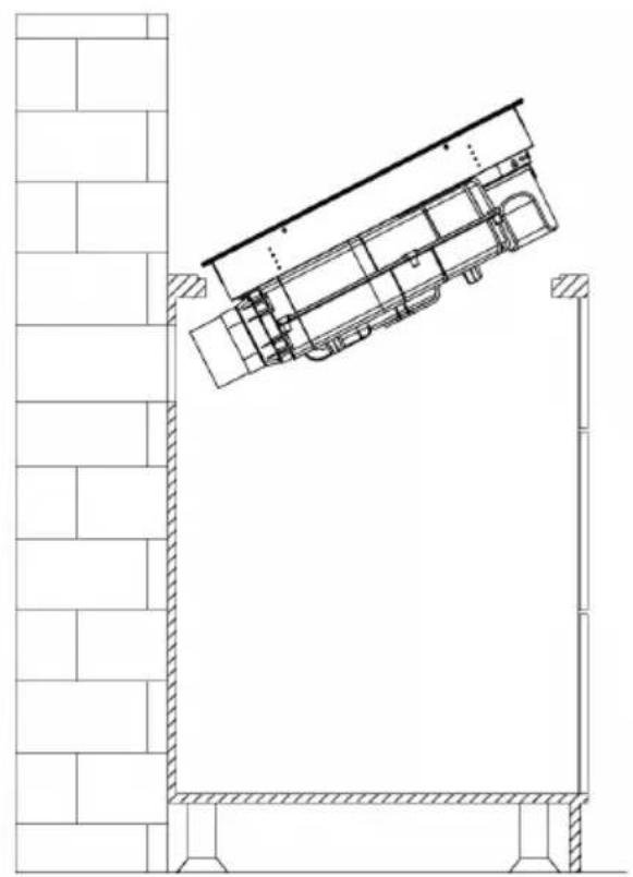
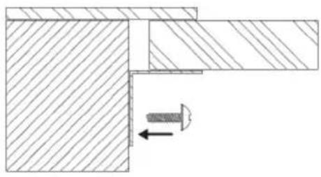
Technical drawing of a mechanical joint or bracket with hatched areas and a central arrow indicating direction (no text or symbols)After installing the device, install four supports on both sides of the device to prevent the device from falling.
INSTALLATION OF THE BENT EXHAUST PIPE FOR EXHAUST OPERATION
Optional accessories
text_image
The accessories shown here can be purchased in addition to the existing accessories on our website, but are not mandatory for installation.Installation of the exhaust pipe
text_image
1 A=H-345 Cut the pipe to the desired length with a saw.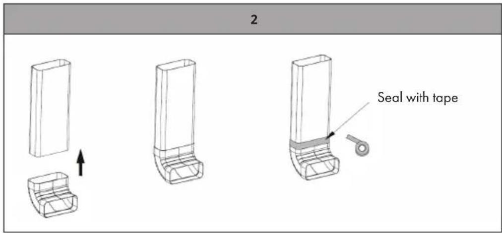
text_image
2 Seal with tape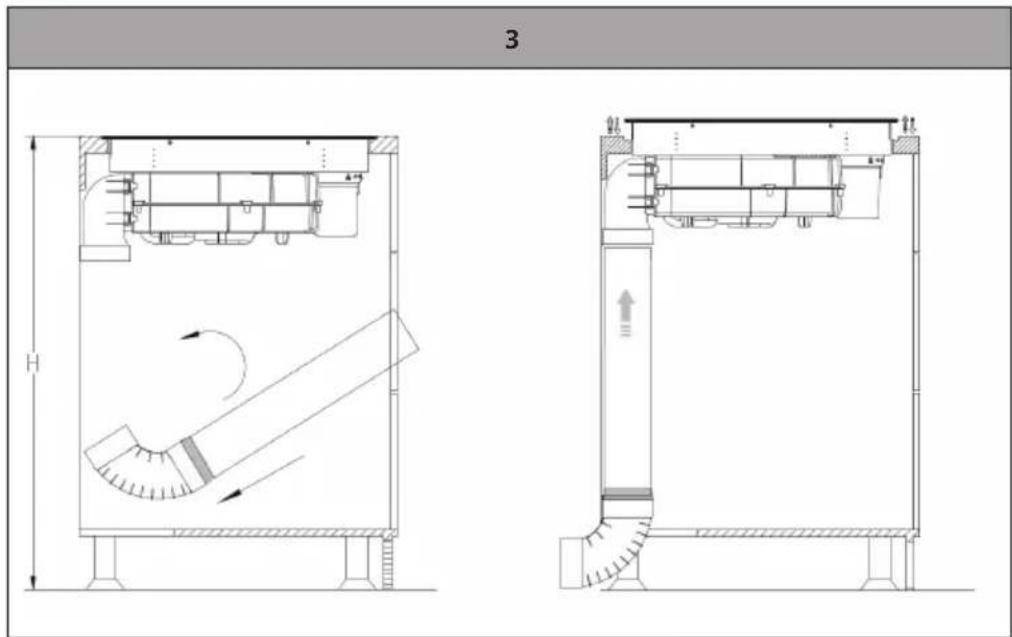
text_image
3 H A B C D E F G H I J K L M N O P Q R S T U V W X Y Z| 4 | 5 |
| After installing the device, install four supports on both sides of the device to prevent the device from falling. |
INSTALLATION OF THE BENT EXHAUST PIPE FOR EXHAUST OPERATION
Dimensions of the required recesses in the kitchen cabinet
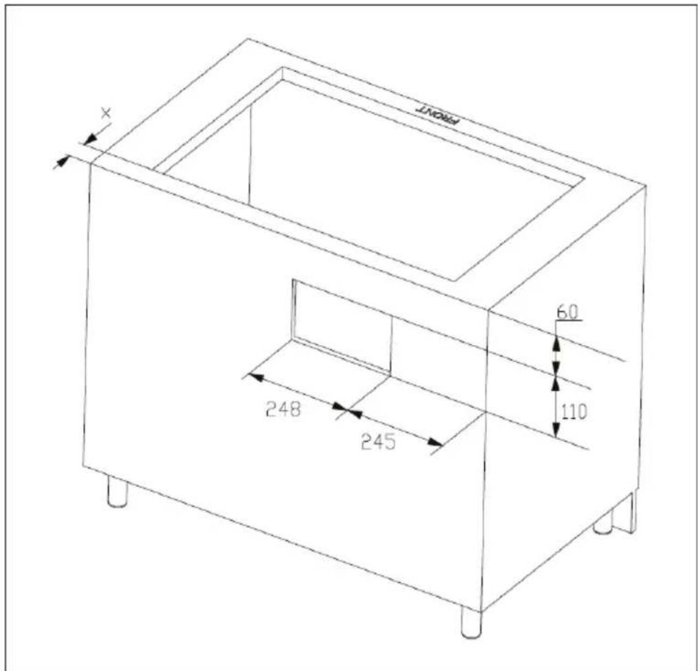
text_image
POINT X 60 110 248 245| Table width (Y) X | |
| 600-650 mm 54 mm | |
| ≥650 mm 65 mm |
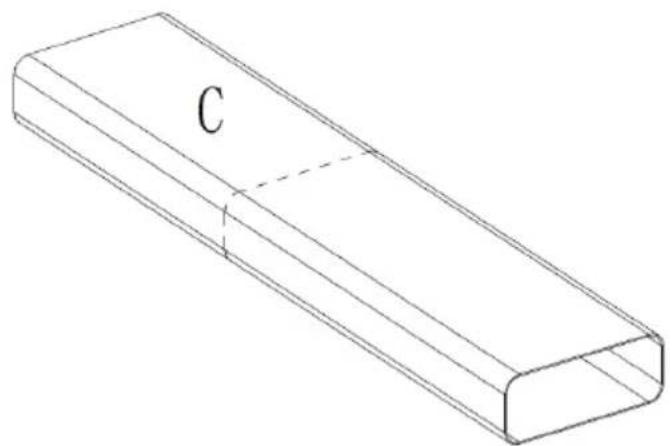
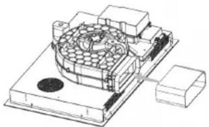
Installation of the straight exhaust pipe
| 1 | |
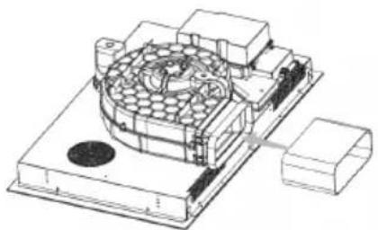
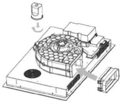 | Attach the straight exhaust pipe adapter by gluing it. |
2
C=X
natural_image
Isometric line drawing of a rectangular prism with labeled point C (no text or symbols beyond label)3
natural_image
Technical line drawing of a mechanical assembly with no visible text or symbols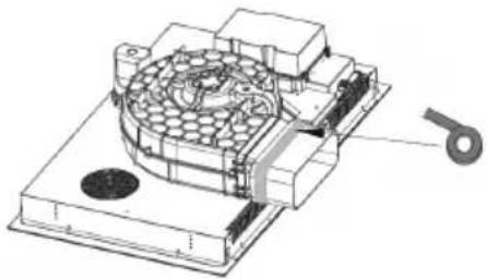
natural_image
Technical illustration of a mechanical assembly with a circular component and a separate part labeled '5' (no text or symbols present)4
natural_image
Technical line drawing of a mechanical assembly mounted on a brick wall, showing structural components and alignment (no text or symbols)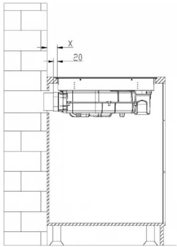
text_image
X 205
natural_image
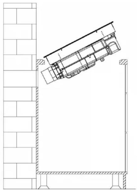
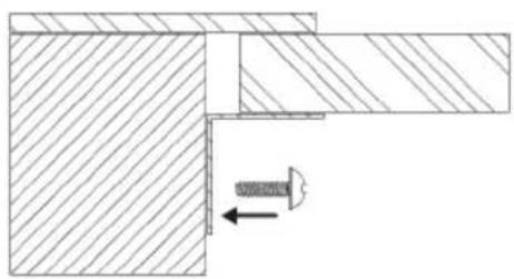
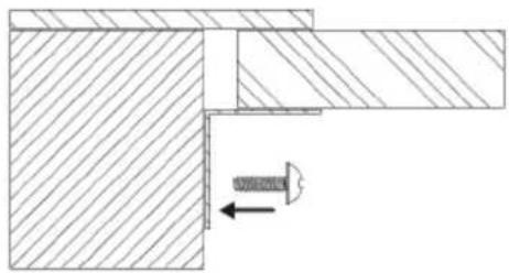
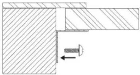
Technical drawing of a mechanical joint or bracket with hatched areas and a central screw (no text or symbols)After installing the device, install four supports on both sides of the device to prevent the device from falling.
ELECTRICAL CONNECTION
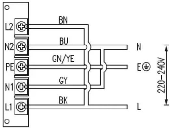
Electrical connection Home connection
text_image
L2 N2 PE N1 L1 BN BU GN/YE GY BK N E⊕ L 220-240V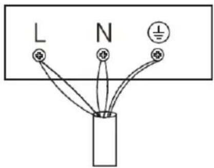
text_image
L N I| Power cable H07RN-F 5G2,5mm ^2 | |||
On/off switch Child safety lock


Connection of cooking zones
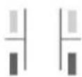
Select the front of the oven

Adjust speed of the fan

Heat retention

Setting the timer

Slider to set timer, heat level or speed
- Status light / indicator light

Display of heating level or speed

Connection display when switching on the fan

Time display
| Button function Please note: | ||
| ●1 | Main switch | Press the button to switch the appliance on or off. The associated indicator light goes on and off. |
| ●2 | Child safety lock | Press and hold the button to activate the child lock. The associated indicator light comes on. Press and hold the button to deactivate the child lock again. The associated indicator light goes on off. |
| ●3 | Bridging button for connecting cooking zones | To share the left cooking zones, briefly press the bridging key on the left side. The indicator light lights up, indicating that the connection of the left cooking zones is active. By default, the power level is set to OFF. You can increase or decrease the power level of the two left cooking zones simultaneously. To disconnect the cooking zones again, press the bridging key again. You can now use the cooking zones independently again.To use the right cooking zones together, briefly press the bridging key on the right side. The indicator light lights up, indicating that the connection of the right cooking zones is active. By default, the power level is set to OFF. You can increase or decrease the power level of the two right cooking zones simultaneously. To disconnect the cooking zones again, press the bridging key again. You can now use the cooking zones independently of each other again. |
●4 | Heat retentionTimer | Press the button to activate the heat retention function. The associated indicator light comes on. The currently active cooking zone switches to the lowest heating level and the display shows [L]. If you press any other button, the keep-warm function will be deactivated and the cooking zone will return to the previous operating status.If no cooking zone has been selected, this button has no function. When a cooking zone has been selected, press this button to enter the time setting. Default is [0]. Slide your finger on the slider to set the time. The time can be set to a maximum of 99 minutes. |
 | Activation of the cooking zone at the top left | The timer and heat output can be set for the cooking zone at the top left. Press the button to activate the cooking zone. The display next to the button shows the current heating output. Slide your finger back and forth on the slider to set the desired heat output. |
| [###] | Activation of the cooking zone at the bottom left | The timer and heat output can be set for the cooking zone at the bottom left. Press the button to activate the cooking zone. The display next to the button shows the current heating output. Slide your finger on the slider to set the time. |
| [###] | Activation of the cooking zone at the top right | The timer and heat output can be set for the cooking zone at the top right. Press the button to activate the cooking zone. The display next to the button shows the current heating output. Slide your finger on the slider to set the time. |
| [###] | Activation of the cooking zone at the bottom rightAdjust speed of the fan | The timer and heat output can be set for the cooking zone at the bottom right. Press the button to activate the cooking zone. The display next to the button shows the current heating output. Slide your finger on the slider to set the time.When the fan is turned on for the first time, the pairing button will light up and the fan will be in pairing state. Slide your finger on the slider to set the desired fan speed between 1-8. If you select [b] at the end of the slider, the fan will run at the highest speed. After 1 minute it then changes to level 8 and after another 8 minutes to level 7. The display above the button shows the current speed. If you press the button while the fan is running, the fan will continue to run for 1 minute and then turn off. |
| LinkageSimple number display | The linkage is activated when the appliance is switched on for the first time and saves the previous status each time the appliance is switched on.To activate or deactivate the hob and hood linkage, press and hold the speed button for 3 seconds.When the cooktop and range hood are linked, the fan speed is synchronized with the current cooktop speed.Example:If the four cooking zones are set to level 8, the fan will also be set to level 8. The highest fan speed is at level 9, the lowest fan speed is at level 1.Displays the current heating level.The display [b] means that the highest heating level or the highest fan speed is set.The [u] display means that there is no pot on the hob.The display [H] means that the hotplate temperature is still very high.The display [0] means that the hob is switched off.The display [E] indicates a malfunction (see chapter Error Messages). | |
| Double number display | Displays the set timer from 00 to 99 minutes.Shows the error code (see chapter Error Messages).The display [D] means that the device is in standby mode. | |
| Slider | For setting the timer, heating level or speed.If a cooking zone is switched off, the controller scans the fan and the other cooking zones and transfers the control function to the still active cooking zones or the fan. | |
Important notes on operation
- Make sure the total power does not exceed 3600 W when the two cooking zones on the same side are working at the same time. If the calculated total power exceeds 3600 W during the setting process, reduce the power of one of the two cooking zones.
- Simultaneously press the right and left bridge buttons to adjust the power of all four cooking zones at the same time. Then press the left bridge button to decrease maximum power or the right bridge button to increase maximum power. There are 5 power levels: 2800 W, 3600 W, 4600 W, 5800 W, 7200 W. If you do not adjust the maximum power for 30 seconds or press the power button, the device will turn off.
- The extractor hood can be operated in two ways: in recirculation mode and in exhaust air mode. Air recirculation mode is set by default. To switch the extractor hood to exhaust air mode, switch off the hob and fan. Then press the hob selection button and the fan button simultaneously for 3 seconds to enter the switching mode. Then press the fan button several times to select the following setting: [0] = recirculation mode or [1 = air extraction mode.
Heat output levels of the hob
| Stage 0 1 2 3 4 5 6 7 8 b | ||||||||||
| Power (W) 0 100 | 200 300 600 1000 1400 | 1600 1800 2500 | ||||||||
Heat output levels of the hob in paired state
| Stage 0 1 2 3 4 5 6 7 8 b | ||||||||||
| Power (W) 0 100 | 200 300 600 1000 1200 | 1400 1600 1800 | ||||||||
Fan levels and fan power
| Stage 0 1 2 3 4 5 6 | 7 8 b | |||||||||
| Air volume (m^3/h) | 0 400 450 500 530 560 580 600 700 750 | |||||||||
| Runtime (min) Long-term operation 8 3 | ||||||||||
How the induction hob works
Induction cooking is an advanced, efficient and affordable cooking technology. It works with the help of electromagnetic vibrations and transfers the heat directly to the pot instead of heating it indirectly via the glass surface. The glass only gets hot because the pot heats it up.
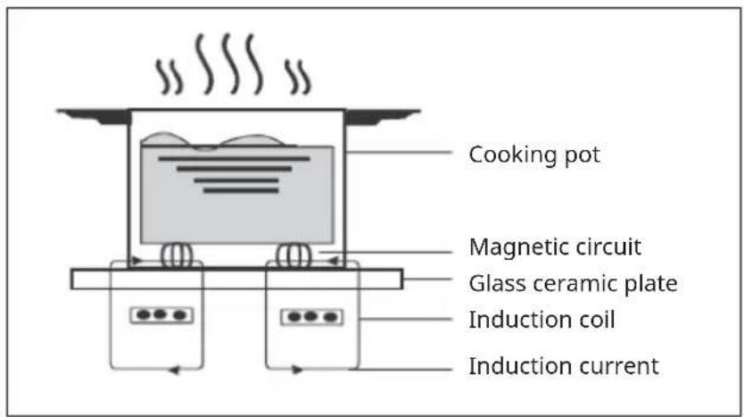
text_image
Cooking pot Magnetic circuit Glass ceramic plate Induction coil Induction currentCorrect operation of the slider
- The buttons on the unit's control panel respond to touch. It is therefore not necessary to apply pressure when touching.
- Use the pad of your finger to touch and not the tip of your finger.
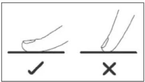
text_image
Diagram showing two hand positions with checkmark and cross symbols, likely indicating correct and incorrect states.• Each time the unit registers a touch, it beeps.
• Make sure that the buttons are always clean and dry and that they are not covered (for example by objects or cloths). Even a thin film of water can make it difficult to operate the keys.
Choosing the right cookware
Note: Only use cookware suitable for induction. Look for the induction symbol on the packaging or on the bottom of the pot. Always lift the pot off the induction hob. Do not pull the pot as this could scratch the glass.
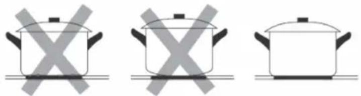
natural_image
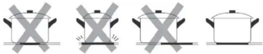
Three identical cooking pots with crossed-out X marks, placed on a flat surface (no text or symbols)Cookware made of the following materials is not suitable: pure stainless steel, aluminium or copper without magnetic underside, glass, wood, porcelain, ceramics and pottery. Do not use cookware that has sharp edges or a rounded bottom.
natural_image
Four identical cooking pots with crossed-out X marks, shown in different orientations (no text or symbols)Make sure the bottom of your pot is level, sits flat on the glass surface and is the same size as the hob. Only use pots whose diameter is as large as the marking on the hob. If you use a slightly larger pot, the energy is consumed at the highest efficiency level. If you use a smaller pot, the efficiency might be lower than expected. Pots with a diameter of less than 140 mm might not be detected by the induction hob. Always place the pot in the middle of the hob.
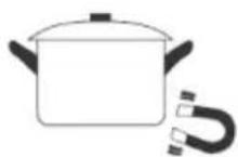
You can perform a magnet test to check the usability. Move a magnet in the direction of the bottom of the pot. If the magnet is attracted to it, the pot is suitable for induction.

WARNING
Risk of fire! Take special care when deep-frying as the oil and fat heat up very quickly. At very high temperatures, oil and grease can ignite spontaneously, and therefore pose an enormous fire risk.
Tips for cooking
- Reduce the heat when the food starts to cook.
- Using a pot lid reduces the preparation time and saves energy by retaining the heat.
- Minimise the amount of water or fat to reduce preparation time.
- Start the cooking process with a high heat setting and reduce the heat as soon as the food has heated up completely.
Simmering, cooking rice
- When simmering, the contents of the pot are cooked below the boiling point at about 85^ . Bubbles occasionally rise to the surface of the cooking liquid. Simmering is the key to delicious soups and delicate stews, as it allows the flavour to develop without overcooking the food. You should also prepare egg-based and flour-thickened sauces below the boiling point.
- Preparing rice using the absorption method may require a higher power setting to ensure that the rice cooks in the recommended time.
Searing steak
- Let the meat rest at room temperature for about 20 minutes.
- Heat a frying pan.
- Rub both sides of the steak with oil. Drizzle some of the oil into the hot pan and then place the steak in it.
- Turn the steak over only once during searing. The length of searing depends on the thickness of the steak and how well done you want it to be in the end. The time can vary from 2-8 minutes per side. Press on the steak (for example with a fork or cooking spoon) to check how cooked through it is. The firmer it feels, the more cooked through it is.
- Then place the steak on a warm plate for a few minutes to rest and tenderise.
Stir-frying food
- Select an induction-compatible shallow wok or large pan.
- Have all the ingredients and accessories ready. Stir-frying should be quick. If you have large quantities of food, fry them in portions and not all at once.
- Preheat the pan briefly and add two teaspoons of oil.
- Fry the meat first and take it out and keep it warm.
- Fry the vegetables while stirring. When the vegetables are hot but still firm to the bite, reduce the heat setting of the hob, place the meat in the pan and add your sauce.
- Gently stir the ingredients together to ensure that everything is warmed up.
- Serve the food immediately.
Note: If a non-magnetic pot (e.g. made of aluminium), a pot of the wrong size or small objects (e.g. knives, forks, keys) are placed on the induction hob, the appliance automatically switches to standby mode after one minute. The fan cools down the unit for another minute.
Set the heating power
| Power level Suitable for | |
| 1-2 | Warming up small amounts of foodMelting chocolateSimmeringSlow heating |
| 3-4 | Warming upRapid simmeringCooking rice |
| 5-6 • Pancakes | |
| 7-8 | Brief fryingCooking pasta |
| b | Deep frying and searingBringing soup to a boilBringing water to a boil |
CLEANING AND CARE OF THE HOB
Note: Before cleaning, always pull the plug out of the socket and allow the device to cool down.
| What How Important! | ||
| Daily contamination on the glass (fingerprints, marks and stains caused by overflowing, non-sugary food and liquids) | 1. Turn the hotplate off.2. Spray on a hotplate cleaner while the plate is still warm but no longer hot.3. Wipe with a damp cloth and dry the plate with a towel.4. Turn the hotplate back on. | ·When the hotplate is switched off, the "Hot surface" indicator goes out even though the hotplate is still hot. Be careful not to burn yourself!·Do not use scouring pads or abrasives as they may damage the finish. Check the package to see if your cleaning agent is suitable for ceramic hotplates.·Do not leave any cleaner residue on the plate, otherwise the glass could tarnish. |
| Spilled food or liquids on the function keys. | 1. Turn the hotplate off.2. Soak the residues.3. Wipe the keys with a damp cloth, soft sponge or kitchen towel.4. Follow steps 2-4 under "Daily contamination". | · The hotplate may beep, switch itself off and the buttons may stop working while there is liquid on them. Make sure that the buttons are clean and dry before switching the plates back on. |
| Overcooked, melted or hot, sugary residues and splashes on the glass. | Remove the dirt with a carpet knife, a razor blade or a scraper for ceramic hotplates, but be careful not to burn yourself on the hot hotplate.1 Turn the hotplate off.2 Hold the scraper at a 30° angle and scrape the dirt into a cold corner of the hotplate.3 Remove the dirt with a cloth or kitchen towel.4 Follow steps 2-4 under "Daily contamination". | · Remove the stains and splashes immediately, as they are more difficult to remove once they have become cold.· Attention: risk of injury! As soon as the safety cover is removed from the carpet knife, the sharp knife will stick out. Handle it carefully so that you do not injure yourself. |
CLEANING AND CARE OF THE EXTRACTOR HOOD
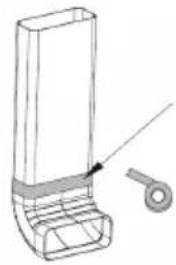
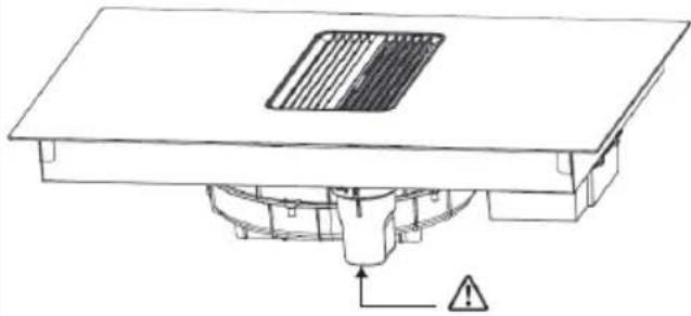 | If you use a damp cloth for cleaning, make sure that no water gets into the slits of the extractor hood.Regularly empty and clean the water cup attached to the bottom of the extractor hood (see arrow). |
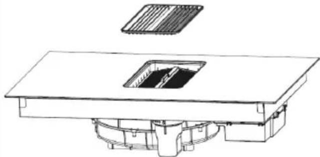 | Take the grid, clean it carefully and then put it back. |
 | Remove the filter holder horizontally. Remove the grease filter from the holder and wash it in the dishwasher or clean the grease filter manually. Dispose of the residual water from the filter holder in the sink.After removing the filter holder, take out the activated carbon filter and replace it. |
| Unscrew the water cup, empty the waste water in it and put it back. |
TROUBLESHOOTING
| Problem Potential cause | Solution | |
| The hob does not turn on. | No power. Make sure that | the induction hob is connected to the mains and switched on. Check whether there is a power outage in your home or in your area. If you have checked everything and the problem persists, contact a qualified technician. |
| The buttons on the control panel do not respond. | The child safety lock is active. | Press and hold the child safety lock button (lock) to deactivate the child lock again. |
| The keys on the control panel are difficult to operate. | There may be a slight water stain on the controls or you may be touching the controls with your fingertip. | Make sure the area around the controls is dry and touch the controls with your fingertip. |
| The glass on the hob is scratched. | The cookware has sharp edges. | Use cookware with a flat, smooth base. |
| Unsuitable or abrasive cleaning equipment is used. | Only clean the surfaces of the hob with a soft cloth. | |
| The induction hob or a cooking zone has switched off unexpectedly, a tone sounds and an error code is displayed. | Technical error. Make a note of the error code and switch off the induction hob. Check the error code in the ERROR MESSAGES chapter. | |
| The induction hob emits a low hum when a high heat setting is selected. | This is due to the technology of induction cooking. | This is normal, but the noise should decrease or disappear as you lower the heat setting. |
| The pans do not get hot and appear on the display. | The induction hob cannot recognise the pan because it is not suitable for induction cooking. | Use cookware suitable for induction cooking. |
| The induction hob cannot detect the pan because it is too small for the cooking zone or is not properly centred on the cooking zone. | Place the pan in the centre, making sure its diameter matches the size of the cooking zone. | |
| Fan noise from the induction hob. | A cooling fan built into your induction hob has switched on to protect the electronics from overheating. It also continues to run briefly after you have switched off the induction hob. | This is normal and requires no action. Do not turn off the power to the induction hob while the fan is running. |
| Some pans make crackling or clicking noises | This can be caused by the construction of your cookware (layers of different metals vibrate differently). | This is normal for cookware and does not indicate a fault. |
| The light is on but the motor does not work. | The fan blades are blocked. | Have the fan blades checked. |
| The capacitor is damaged. | Have the capacitor replaced. | |
| The motor is damaged. | Have the motor replaced. | |
| The internal wiring of the motor is broken or disconnected. An unpleasant odour may develop. | Have the motor replaced. | |
| Lights and engine do not work. | The light is broken. Have the light replaced. | |
| The mains cable is loose. Have an electrician check the wiring. | ||
| Oil leaks. The extractor hood | d vent is not sealed. | Take off the outlet and seal it with glue. |
| Vibrations. If the fan blades | are damaged, they can cause vibration. | Have the fan blades checked. |
| The motor is not properly fastened. | Fasten the motor. | |
| The cooker hood is not firmly attached. | Attach the extractor hood. | |
| Insufficient extraction of the hood. | The distance between the extractor hood and the cooking surface is too great. | Reduce the distance. |
| Too much draft through open doors or windows. | Close open doors or windows. | |
| The device is tilted. The mounting screws are not tightened. | Tighten the fixing screw and set it level. | |
| Tighten the suspension screw and set it level. | ||
| The LED does not light up when the device is plugged in. | No power. Have the device checked. | |
| The circuit board and the connected display are faulty. | Have the connection checked. | |
| The circuit board is damaged. | Have the circuit board replaced. | |
| The display is damaged. Have the display replaced. | ||
| Some buttons do not work or the LED display is abnormal. | The display is damaged. Have the display replaced. | |
| The cooking mode indicator lights up, but the heating process does not start. | The hob is too hot. Let the hob cool down and check whether the ventilation openings are blocked. | |
| The fan is not working properly | Check whether the fan is running normally. Have it replaced if necessary. | |
| The power supply circuit board is damaged. | Have the circuit board replaced. | |
| The heating stops suddenly during operation and the display shows [u]. | Wrong pan type. Use suitable cookware. | |
| Pan diameter too small. Use suitable cookware. | ||
| The device is overheated. | Allow the device to cool down and restart it. | |
| The cooking zones on the same side display [u]. | The circuit board and the connected display are faulty. | Have the connection checked. |
| The display panel of the communication part is damaged. | Have the display panel replaced. | |
| The main circuit board is damaged. | The motherboard is damaged. | |
| Have the motherboard replaced. | The fan motor is broken. | Have the fan replaced. |
ERROR NOTIFICATIONS
| Code Potential cause Solution | ||
| 01 The oven's NTC temperature sensor is faulty. | Have the NTC temperature sensor replaced. | |
| 02 Cooker surface NTC temperature sensor short circuit. | Have the NTC temperature sensor replaced. | |
| 03 The NTC temperature of the cooker surface is too high | Turn off the device and wait for it to cool down, then resume operation. | |
| 04 The cooling NTC temperature sensor is faulty. | Have the NTC temperature sensor replaced. | |
| 05 Short circuit of the heater NTC temperature sensor. | Have the NTC temperature sensor replaced. | |
| 06 The heat dissipation NTC temperature sensor is too hot. | Turn off the device and wait for it to cool down, then resume operation. | |
| 07 The input voltage is too low. Check if the input voltage is lower than 150 V. | ||
| 08 The input voltage is too high. Check if the input voltage is higher than 270 V. | ||
| 09 Connection error. Have checked whether the connection error between the display panel and the induction cooker circuit board is faulty and have the communication cable replaced. | ||
| 10 NTC failure on the surface of the oven. | Have the cooktop surface temperature sensor checked to ensure that it is in contact with the cooktop surface and that there is glass adhesive contact. | |
| 11 Internal error, open plate, no sync signal. | Have checked whether the cable pulley is not receiving a sync signal and decide whether the cable pulley needs to be replaced. | |
| 12 The fan is not working. Check if the fan is on or restart the device again. | ||
| 13 The device runs dry. Turn off the device and restart it. | ||
| 14 Internal error on the display board | Have the display board replaced. | |
PRODUCT DATA SHEET EXTRACTOR
Information according to Regulation (EU) No 65/2014
Measurement and calculation methods according to EN 61591:1997+A1:2006+A2:2011+A11:2014+A12:2015
| Article number 10046663, 10046664, 10046667, 10046668, 10046661, 10046662, | |||
| Designation Symbol Value Unit | |||
| Annual energy consumption AEC | hood | 11.6 kWh/year | |
| Energy efficiency class A++ | |||
| Fluid-dynamic efficiency FDE | hood | 29.3 | |
| Fluid dynamic efficiency class A | |||
| Lighting efficiency LE | hood | k. A. Lux/W | |
| Lighting efficiency class k. A. | |||
| Grease separation efficiency GFE | hood | 77.5 % | |
| Class for grease separation efficiency | C | ||
| Air flow at minimum and at maximum speed in normal operation, excluding operation on the intensive or fast speed setting | 361.0 / 595.0 m3/h | ||
| Air flow when operating on the intensive or fast speed setting | 745.4 m3/h | ||
| A-rated airborne noise emissions at minimum and maximum available speed during normal operation | 58 / 62 | dB | |
| A-rated airborne noise emissions during operation at the intensive or high-speed stage | 71 | dB | |
| Power consumption in off-mode | Po | k. A. W | |
| Power consumption in standby mode | Ps | 0.66 W | |
| Contact details Chal-Tec GmbH, Wallstraße 16, 10179 Berlin, Germany. | |||
PRODUCT DATA SHEET HOB
| Symbol Value Unit | ||||
| Model identifier 10046663, 10046664, 10046667, 10046668, 10046661, 10046662, | ||||
| Type of hob Built-in hob | ||||
| Number of cooking zones and/or cooking surfaces | 2 | |||
| Heating technology (Induction cooking zones and cooking surfaces, radiant cooking zones, hotplates) | Induction cooking zones | |||
| For circular cooking zones or surfaces: Diameter of the usable surface for each electrically heated cooking zone, to the nearest 5 mm. | ∅ | N/A N/A | cm | |
| For non-circular cooking zones or surfaces: Length and width of usable surface for each electrically heated cooking zone and each electrically heated cooking surface, accurate to 5 mm. | L B | Left Right | 47*17,5 47*17,5 | cm |
| Energy consumption per cooking zone or surface per kg | EC Electrical Hob | Left Right | 189,4 187,4 | Wh/kg |
| Energy consumption of the hob per kg | EC Electrical Hob | 188,4 Wh/kg | ||
NOTES ON ENVIRONMENTAL PROTECTION
- Make sure there is sufficient air supply during cooking so that the cooker hood can work efficiently and with low operating noise.
- Adjust the fan speed to the amount of steam produced while cooking. Use the intensive mode only when necessary. The lower the fan speed, the less energy is consumed.
- If large amounts of steam are produced when cooking, select a higher fan speed in time. If the cooking steam has already spread throughout the kitchen, the cooker hood must be operated for longer.
- Switch off the cooker hood when it is no longer needed.
- Switch off the lighting when it is no longer needed.
- Clean the filter at regular intervals and replace it if necessary to increase the effectiveness of the ventilation system and prevent fire hazards.
- Always put the lid on when cooking to reduce cooking steam and condensation.
DISPOSAL CONSIDERATIONS
natural_image
Symbol of a trash bin crossed with a diagonal line, no text or numbers presentIf there is a legal regulation in your country regarding the disposal of electrical and electronic equipment, this symbol on the product or on the packaging indicates that this product must not be disposed of with household waste. Instead, it must be taken to a collection point for the recycling of electrical and electronic equipment. By disposing of this product in accordance with the regulations, you protect the environment and the health of those around you from negative consequences. For information on recycling and disposal of this product, contact your local government or household waste disposal service.
MANUFACTURER & IMPORTER (UK)
Manufacturer:
Chal-Tec GmbH, Wallstrasse 16, 10179 Berlin, Germany.
Importer for Great Britain:
Berlin Brands Group UK Limited
PO Box 42
272 Kensington High Street
London, W8 6ND
United Kingdom
Estimado cliente:
text_image
QR code image containing encoded data, no visible human-readable textÍNDICE
text_image
Exploded view diagram of household air conditioner components with numbered parts and directional arrowstext_image
Technical diagram of a mechanical device with labeled components and Chinese annotations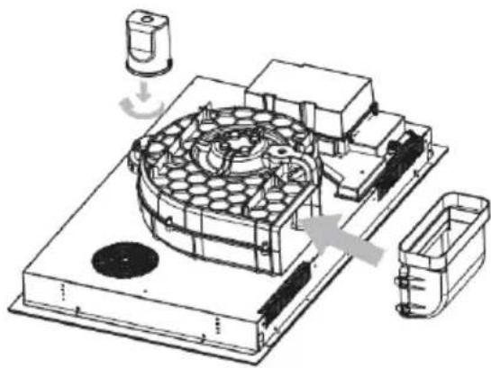
natural_image
Technical line drawing of a mechanical assembly with no visible text or symbolstext_image
MIN 220 ≥100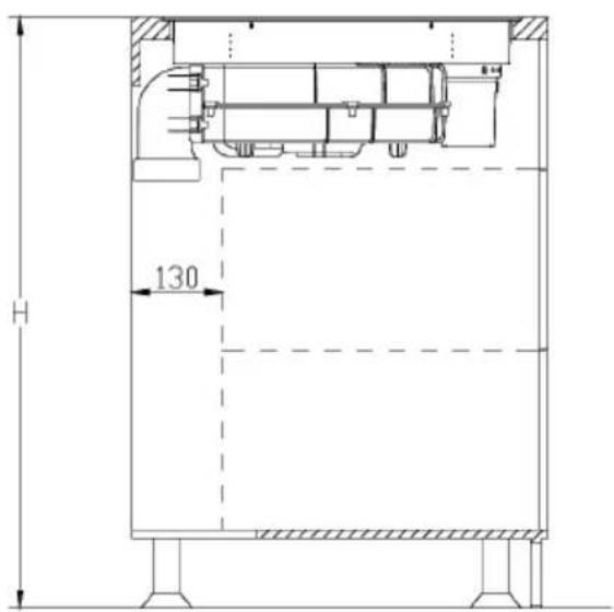
text_image
H 130natural_image
Technical line drawings of a rectangular box with an open lid and side view, showing dimensions (no text or symbols)natural_image
Simple line drawing of a rectangular box and a stacked container with an upward arrow (no text or symbols)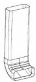
natural_image
Technical line drawing of a mechanical component with a circular end and a handle (no text or symbols)natural_image
Technical schematic of a mechanical or fluid system with directional arrows and dimension lines (no text or symbols)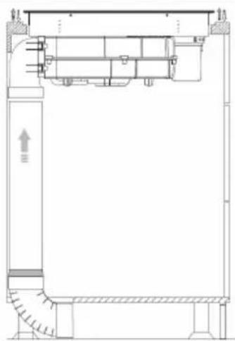
natural_image
Architectural floor plan showing room layout and structural elements (no text or labels)4
text_image
Bnatural_image
Technical line drawings of two mechanical components with no visible text or symbols4
natural_image
Technical line drawing of a mechanical assembly mounted on a brick wall, showing structural components and alignment (no text or symbols)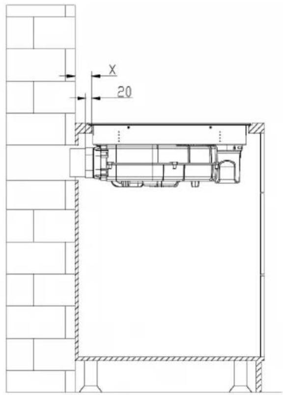
text_image
X 205
natural_image
Technical drawing of a mechanical joint or bracket with hatched areas and a central screw (no text or symbols)text_image
Technical diagram with a rectangular outline and dimension labels, including symbols like 'a', 'b', and directional arrows.
text_image
Diagram showing two hand positions with checkmark and cross symbols, likely indicating correct and incorrect states.natural_image
Three identical cooking pots with crossed-out X marks, no text or symbols presentnatural_image
Four identical cooking pots with crossed X marks, shown in different orientations (no text or symbols)natural_image
Symbol of a trash bin crossed with a diagonal line, no text or numbers presentBerlin Brands Group UK Limited
PO Box 42
272 Kensington High Street
London, W8 6ND
Reino Unido
Cher client, chère cliente,
text_image
QR code image containing encoded data, no visible human-readable textSOMMAIRE
text_image
Exploded view diagram of household air conditioner components with numbered parts and directional arrowsInstallation standard
text_image
496 R10 FACE AVANT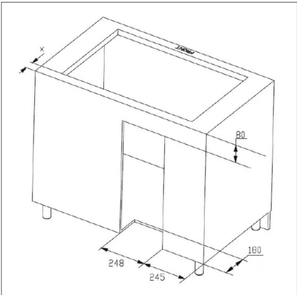
text_image
X 80 248 245 180 FRONTnatural_image
Technical line drawing of a mechanical assembly with no visible text or symbolstext_image
MIN 220 ≥100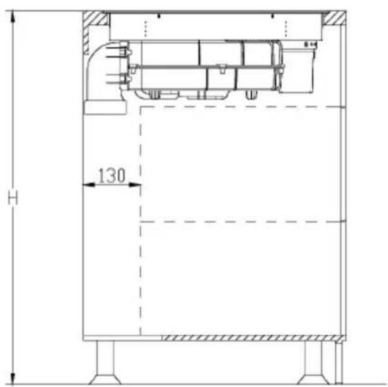
text_image
H 130natural_image
Technical line drawings of a rectangular box with an open lid and side view, showing dimensions (no text or symbols)natural_image
Simple line drawing of a rectangular box and a stacked container with an upward arrow (no text or symbols)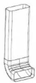
natural_image
Technical line drawing of a mechanical component with a separate ring detail (no text or symbols)natural_image
Technical schematic of a mechanical or fluid system with directional arrows and dimension lines (no text or symbols)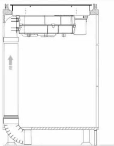
natural_image
Architectural cross-section diagram of a building facade with structural elements and stairs (no text or labels)4
text_image
Bnatural_image
Architectural floor plan showing room layout with furniture and a directional arrow (no text or labels)
natural_image
Architectural cross-section diagram of a building facade with internal structural elements and a small component (no text or labels)6
natural_image
Technical drawing of a mechanical joint or bracket with hatched areas and a central arrow indicating direction (no text or symbols)natural_image
Technical line drawing of a mechanical assembly with no visible text or symbols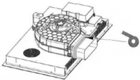
natural_image
Technical illustration of a mechanical assembly with a circular component and a separate part labeled '5' (no text or symbols present)4
text_image
Technical drawing showing two views of a building interior with structural components and dimension annotations5
text_image
Diagram showing two hand positions with checkmark and cross symbols, likely indicating correct and incorrect states.natural_image
Three identical cooking pots with crossed-out X marks, no text or symbols presentnatural_image
Four identical cooking pots with crossed X marks, shown in different orientations (no text or symbols)text_image
Prohibition sign for a trash bin with crossed and unbroken lines indicating restriction or exclusionBerlin Brands Group UK Ltd
PO Box 42
272 Kensington High Street
London, W8 6ND
United Kingdom
Gentile cliente,
text_image
QR code image containing encoded data, no visible human-readable textINDICE
text_image
Exploded view diagram of household air conditioner components with numbered parts and directional arrowsnatural_image
Technical line drawing of a mechanical assembly with no visible text or symbolstext_image
MIN 220 ≥100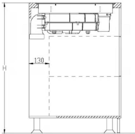
text_image
H 130natural_image
Technical line drawings of a rectangular box with an open lid and side view, showing dimensions (no text or symbols)natural_image
Simple line drawing of a rectangular box and a stacked container with an upward arrow (no text or symbols)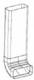
natural_image
Technical line drawing of a mechanical component with a circular end and a handle (no text or symbols)natural_image
Technical schematic of a mechanical or fluid system with directional arrows and dimension lines (no text or symbols)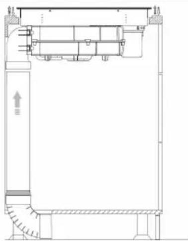
natural_image
Architectural cross-section diagram of a building facade with structural elements and stairs (no text or labels)4
text_image
Bnatural_image
Technical line drawing of a 3D mechanical part with three views: front, side, and top (no text or symbols)natural_image
Isometric line drawing of a rectangular prism with labeled point C (no text or symbols beyond label)3
natural_image
Technical line drawing of a mechanical assembly with no visible text or symbols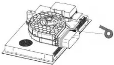
natural_image
Technical illustration of a mechanical assembly with a circular component and a separate part labeled '5' (no text or symbols present)4
natural_image
Technical line drawing of a mechanical assembly mounted on a brick wall, showing structural components and alignment (no text or symbols)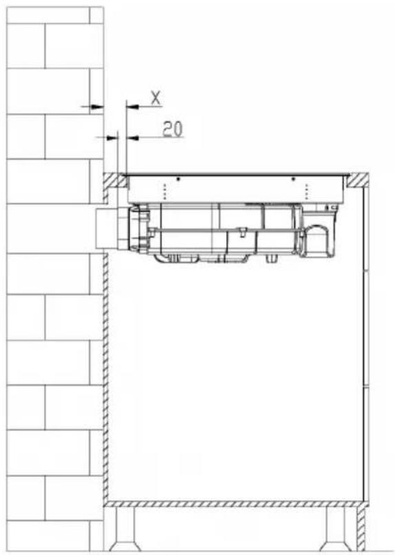
text_image
X 205
natural_image
Technical drawing of a mechanical joint or bracket with hatched areas and a central screw (no text or symbols)text_image
Technical diagram with a rectangular outline and dimension labels, including symbols like 'a' and directional arrows.
text_image
Diagram showing two hand positions with checkmark and cross symbols, likely indicating correct and incorrect states.natural_image
Three identical cooking pots with crossed X marks, no text or symbols presentnatural_image
Four identical cooking pots with crossed-out X marks, shown in different orientations (no text or symbols)natural_image
Symbol of a trash bin crossed with a diagonal line, no text or numbers presentPRODUTTORE E IMPORTATORE (UK)
Produttore:
Chal-Tec GmbH, Wallstraße 16, 10179 Berlino, Germania.
Berlin Brands Group UK Limited
PO Box 42
272 Kensington High Street
London, W8 6ND
United Kingdom

area
| Category | Value | | -------- | ----- | | A | 100 | | B | 100 | | C | 100 | | D | 100 | | E | 100 | | F | 100 | | G | 100 | | H | 100 | | I | 100 | | J | 100 | | K | 100 | | L | 100 | | M | 100 | | N | 100 | | O | 100 | | P | 100 | | Q | 100 | | R | 100 | | S | 100 | | T | 100 | | U | 100 | | V | 100 | | W | 100 | | X | 100 | | Y | 100 | | Z | 100 |