Easy 1881 - Cooker NOVY - Free user manual and instructions
Find the device manual for free Easy 1881 NOVY in PDF.

User questions about Easy 1881 NOVY
0 question about this device. Answer the ones you know or ask your own.
Ask a new question about this device
Download the instructions for your Cooker in PDF format for free! Find your manual Easy 1881 - NOVY and take your electronic device back in hand. On this page are published all the documents necessary for the use of your device. Easy 1881 by NOVY.
USER MANUAL Easy 1881 NOVY
natural_image
Technical line drawing of a mechanical component with a rectangular plate and internal slot (no text or symbols)NOVY
1881-g1 Recirculation/Duct out
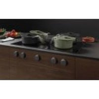
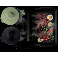
Novy Easy 80 Matte Line
1861-g1 Recirculation/Duct out
INHOUD
1 ALGEMENE INFORMATIE 4

2 MILIEU EN BESPARING 5
4 BESCHRIJVING VAN HET APPARAAT 8
4 BESCHRIJVING VAN HET APPARAAT
text_image
Technical diagram of a device's internal structure with numbered components, likely for assembly or maintenance instructions.text_image
Diagram showing a hand pointing at a row of vertical lines with an arrow indicating direction, possibly illustrating a basic pattern or counting concept.text_image
Diagram showing a hand pointing at a row of vertical lines with an arrow indicating direction, possibly illustrating a vector or pattern concept.natural_image
Technical diagram of an air duct system with airflow arrows indicating movement (no text or symbols)natural_image
Technical line drawing of a mechanical assembly with internal components and directional arrows (no text or symbols)natural_image
Four geometric shapes with diagonal cross marks on horizontal lines, no text or symbols presentnatural_image
Diagram of a hand pressing down on a grid-like structure mounted on a flat base (no text or symbols)natural_image
Technical diagram of a mechanical component with a magnified inset showing internal structure (no text or symbols)natural_image
Technical line drawing of a mechanical component with mounting base and internal housing (no text or symbols)Reinigen vetfilter
natural_image
Technical line drawing of a mechanical assembly with no visible text or symbolsNa het vervangen
text_image
Technical diagram of a device assembly with numbered components for identificationtext_image
Diagram showing a hand pointing at vertical lines with an arrow indicating direction, possibly illustrating a basic arithmetic or symbolic concept.text_image
A2 A1 B2 B11851 /
1861 /
1861-g1
text_image
C2 C1 D2 D11871 /
1881 /
1881-g1
text_image
Diagram showing a hand pointing at vertical lines with an arrow indicating direction, possibly illustrating a basic arithmetic or symbolic concept.natural_image
Technical diagram of an air duct system with cooling fins and airflow arrows (no text or labels)natural_image
Technical line drawing of a mechanical assembly with internal components and directional arrows (no text or symbols)natural_image
Four geometric shapes with diagonal cross marks, no text or symbols presentnatural_image
Diagram of a hand pressing down on a mechanical component with no visible text or symbolsnatural_image
Technical line drawing of a mechanical assembly with a rectangular component and curved base (no text or symbols)natural_image
Technical line drawing of a mechanical assembly with no visible text or symbols* Mode: E = évacuation, R = recyclage.
Activer/désactiver le Power
text_image
Technical diagram of a device assembly with numbered components for identificationtext_image
Diagram showing a hand pointing to vertical lines with an arrow indicating direction, possibly illustrating a basic arithmetic or symbolic concept.text_image
Diagram showing a hand pointing at vertical lines with an arrow indicating direction, possibly illustrating a basic arithmetic or symbolic concept.natural_image
Technical diagram of an air vent assembly with cooling fan and ventilation duct (no text or labels)natural_image
Technical diagram of a mechanical assembly with internal components and directional arrows (no text or labels)natural_image
Four geometric shapes with diagonal cross marks, no text or symbols presentnatural_image
Diagram of a hand pressing a slotted rectangular component on a flat base (no text or symbols)natural_image
Technical diagram of a mechanical component with a magnified inset showing internal structure (no text or symbols)natural_image
Technical line drawing of a mechanical assembly with a rectangular component and mounting base (no text or symbols)natural_image
Technical line drawing of a mechanical assembly with no visible text or symbolsNach dem Austausch:
2.2 Disposal of old appliance 131
2.3 Tips for reducing energy consumption and increasing efficiency 132
3 USING THE APPLIANCE 133
3.1 First use of the appliance 133
3.2 Precautions against damage 133
4 DESCRIPTION OF THE DEVICE 134
4.1 Principle of induction 134
4.2 Technical specifications of the induction hob 135
4.3 Noise caused by induction 135
4.4 Global overview 136
5 INDUCTION HOB 137
5.1 Controlling the induction hob 137
5.2 Control keys and slide operation 137
5.3 Controlling the hob 138
5.3.1 Switch on and off 138
5.3.2 Pan detection 138
5.3.3 Indication of residual heat 139
5.3.4 Power function and Super Power function 139
5.3.5 Timer function 142
5.3.6 Programming auto heat up 143
5.3.7 Stop & Go function 144
5.3.8 Recall function 144
5.3.9 Keep warm function 144
5.3.10 Flexzone 145
5.3.11 Grill function 146
5.3.12 Locking the controller 146
6 EXTRACTOR 147
6.1 Control panel 147
6.2 Control keys and slide operation 147
6.3 Extraction mode 1851 / 1871 & 1861-g1 / 1881-g1 (optional setting) ^1 148
6.4 Recirculation mode 1861 / 1881 & 1861-g1 / 1881-g1 (default setting) 148
6.5 Extractor controls 149
6.5.1 Switch on and off 149
6.5.2 Automatic extraction 149
6.5.3 Automatic run-on function 150
7 CLEANING INDICATIONS 151
7.1 Grease filter cleaning indicator 151
7.2 Recirculation filter replacement indicator 1861 / 1881 & 1861-g1 / 1881-g1 (in recirculation mode) 152
8 COOKING ADVICE 153
9 CLEANING AND MAINTENANCE 155
9.1 Maintenance of the hob 155
9.2 Maintenance of the extractor 158
9.2.1 Remove the inlet grille 158
9.2.2 Replace inlet grille 158
9.2.3 Cleaning the grease filter 159
9.2.4 Replacing the recirculation filter 1861 / 1881 & 1861-g1 / 1881-g1 (in recirculation mode) 160
9.2.5 Setting the recirculation filter usage time (only for 1861-g1 / 1881-g1) 161
10 TROUBLESHOOTING MINOR FAULTS 164
10.1 Messages on the hob 164
10.2 Messages at the extraction 165
10.3 Service 165
OVERVIEW FUNCTIONS NOVY EASY 166
1GENERALINFORMATION
Carefully read the safety instructions, mounting instructions and user manual before installation and putting it into operation.
The safety instructions are listed in a separate booklet supplied with the appliance and listed on our website www.novy.com.
Follow the safety instructions, mounting instructions and user manual to prevent injury and material damage.
This manual makes use of a number of symbols. The meanings of these symbols are given below.
| Symbol | Meaning | |
 | Indication Explanation of an indication on the device. | |
 | Information/Warning | This symbol indicates an important tip or a dangerous situation |
2ENVIRONMENTAND SAVINGS
2.1 Packaging material
This appliance is protected against damage during transport by packaging. The materials used are not hazardous to the environment and are suitable for recycling. Ensure environmentally-friendly disposal of the packaging.
2.2 Disposal of old appliance
Your appliance also contains many materials that can be recycled.
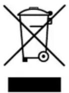
Therefore, used appliances should be separated from other waste. The recycling of appliances organised by your manufacturer is in this way carried out under the best conditions, in accordance with European Directive 2012/19/EU on electrical and electronic waste. Ask your municipality or your salesperson about the closest collection point for your old appliance.
Keep old appliances out of the reach of children.
2.3 Tips for reducing energy consumption and increasing efficiency
The new appliance is exceptionally efficient and economical with energy. Some tips follow below for making your appliance even more energy-efficient and efficient.
Choose a cooking zone that matches the size of the pan. The bottom of the pan should cover the cooking zone as much as possible.
Make sure the pan is always in the centre of the cooking zone.
- Use cookware with a base diameter that matches the diameter of the cooking zone.
Place lids on pans. This prevents unnecessary heat escaping and reduces cooking fumes and condensation.
Use pans with flat bottoms. A pan with a non-flat bottom consumes more energy.
Use cookware that matches the amount of food.
A small pan requires less energy than a large, not-quite-full pan.
Use as little water as possible. The more water in the pan, the more energy is needed to heat it up.
After boiling or frying, switch back to a lower power setting in time to reduce energy consumption and to limit overproduction of vapours.
Position your cookware in such a way that rising vapours reach the extraction surface of the fan
Turn on the appliance's fan at the lowest speed when you start cooking to control humidity and eliminate cooking odours.
Increase the appliance's fan speed only when the amount of cooking vapour requires it.
Use the highest fan speed only when absolutely necessary.
If a lot of cooking vapour is released, switch to a higher fan speed in time. This is more efficient than trying to catch vapour that has already spread throughout the kitchen by using the appliance for a long time.
Use the delay mode if the appliance has one. Do not let the appliance ventilate unnecessarily after cooking.
Keep the appliance filter/filters clean to optimise grease and odour filtering efficiency.
- Ensure adequate air supply in the room, so that the appliance can operate efficiently and economically.
Avoid any draught above the cooking surface for efficient operation.
3 USING THE APPLIANCE
3.1 First use of the appliance
Scan your QR code on the warranty sticker and register your device.
-
Remove all labels and stickers from the glass.
– Clean the glass plate before using the cooktop for the first time as follows: -
Use a damp, soft cloth or a non-scratch, non-abrasive sponge.
- Clean using a cleaner specifically designed for ceramic glass. Always follow the manufacturer's instructions for the cleaning product.
- Dry the glass with a microfibre cloth to achieve a streak-free, glossy finish..
- See chapter 9.1 for full instructions on cleaning the cooktop after use.
3.2 Precautions against damage
Damaged cooking pans or cooking pans with rough bases (cast iron without enamelling) can cause damage to the glass.
- Ensure that the outside of the pan is dry and clean. Make sure there are no food residues or other particles on the hob or underneath the cookware, as these may cause scratches or damage.
Sand or other abrasive materials may cause damage to the glass.
- Do not allow items (even small ones) to fall on the glass.
- Avoid the impact of cooking pans against the edge of the glass.
Do not place or leave empty cooking pans on the hob.
– Never place a hot pan on the control zone.
4 DESCRIPTION OF THE DEVICE
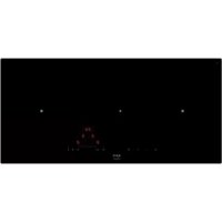
The appliance is an induction hob with integrated worktop extraction. The induction hob has 4 cooking zones with an integrated extractor at the centre of the hob that ensures the removal of cooking vapours.
The hob and extractor can be operated separately. You will find an explanation of the operation of the device further in this manual.
4.1 Principle of induction
There is an induction coil under each cooking zone. When this is on, it produces a variable electromagnetic field that produces an induction current in the bottom of the cooking pan. This results in the warming up of the cooking pan on the cooking zone.
Of course, suitable cooking pans are required for this:
- Recommended cooking pans include those with a magnetic base (you can check this using a magnet): a cast iron kettle, black iron pan, enamelled metal cooking pans, stainless steel pans with magnetic base, etc.
– Unsuitable cooking pans include copper, stainless steel, aluminium, glass, wood, ceramics, pottery, stainless steel without magnetic base, etc.
The induction cooking zone immediately takes the size of the cooking pan into account. If the diameter is too small, the cooking pan will not work. The diameter varies as a function of the diameter of the cooking zone. Should the cooking pan not be adjusted to the hob, the symbol will continue to flash.
4.2 Technical specifications of the induction hob
| Type | 1851 /1861 / 1861-g1 | 1871 / 1881 / 1881-g1 | |
| Total power 7400 | 7400 | W | |
| Energy consumption for the hob EChob** | 185,1 | Wh/kg | |
| Front left heating zone 240 x 210 | 220 x 210 | mm | |
| Minimum detection ∅ 110 | ∅ 110 | mm | |
| Nominal level* 2100 | 2100 | W | |
| Power level* 2300 | 2300 | W | |
| Super Power* 3000 | 3000 | W | |
| Standardised cookware category** | A | A | |
| Energy consumption ECcw** | 186,3 | Wh/kg | |
| Rear left heating zone 240 x 210 | 220 x 210 | mm | |
| Minimum detection ∅ 110 | ∅ 110 | mm | |
| Nominal level* 2100 | 2100 | W | |
| Power level* 2300 | 2300 | W | |
| Super Power* 3000 | 300O | W | |
| Standardised cookware category** | A | A | |
| Energy consumption ECcw** | 183,9 | Wh/kg | |
| Front right heating zone 240 x 210 | ∅ 175 | mm | |
| Minimum detection ∅ 110 | ∅ 90 | mm | |
| Nominal level* 2100 | 1400 | W | |
| Power level* 2300 | 2100 | W | |
| Super Power* 3000 | - | W | |
| Standardised cookware category** | A | A | |
| Energy consumption ECcw** | 186,3 | Wh/kg | |
| Rear right heating zone 240 x 210 | ∅ 175 | mm | |
| Minimum detection ∅ 110 | ∅ 90 | mm | |
| Nominal level* 2100 | 1400 | W | |
| Power level* 2300 | 2100 | W | |
| Super Power* 3000 | - | W | |
| Standardise cookware category** | A | A | |
| Energy consumption ECcw** | 183,9 | Wh/kg | |
* the power transfer may vary, dependent on the sizes and the materials of the cooking pans
** calculated following the methods for measuring the performance (EN 60350-2)
4.3 Noise caused by induction
When using an induction hob, all kinds of noises may occur. These noises are dependent on the construction and the materials of the bottom of the cooking utensils.
Humming
This occurs when cooking at a higher power and this is caused by the amount of energy that is transferred from the hob to the cooking utensils. The noise disappears or becomes weaker when you set the hob to a lower position.
Sputtering
This noise occurs when the utensils consist of layers of different materials. The noise is caused by vibrations in the areas where the different material layers touch each other.
Whistling
Such noises generally arise when cooking with utensils consisting of layers of different materials and when two adjacent cooking zones are used simultaneously at maximum power. The whistling noise disappears or becomes weaker when you set the hob to a lower position.
Clicking
At lower power positions clicking noises may occur at electronic switches.
Buzzing
A buzzing sound may occur when the fan is switched on. This fan cools the electronics at intensive use of the hob. When the temperature is too high, the fan will keep running after the hob has been switched off.
4.4 Global overview
text_image
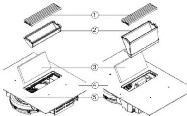
Technical diagram of a mechanical assembly with numbered components, likely illustrating a multi-stage assembly or mounting process.| 1 Inlet grille |
| 2 Grease filter, filter type depending on model |
| 3 Recirculation filter 1861 / 1881 / 1861-g1 / 1881-g1^1 |
| 4 Induction hob |
| 5 Controls |
5INDUCTIONHOB
5.1 Controlling the induction hob
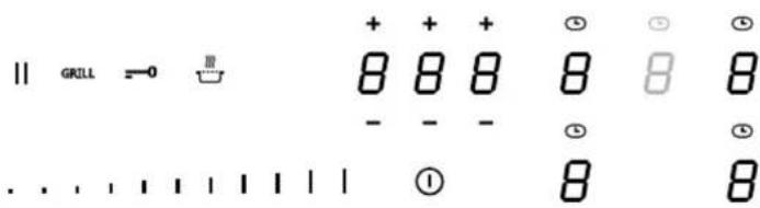
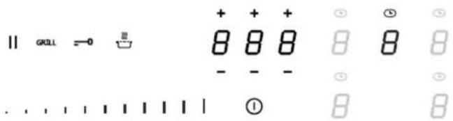
text_image
|| GRILL =0 8 8 8 8 8 8 - - - ① 8 8| Hob control | |
| Indication and selection of timer time | 8 8 8 |
| Slider control | |
| On/off control key hob | 1 |
| Zone selection key | 8 |
| Flexzone indication | 7 |
| Timer indicator | |
| Stop & Go control key | 11 |
| Grill function key | GRILL |
| Lock key | |
| Keep warm function key | |
5.2 Control keys and slide operation
The device is equipped with touch control keys with which you can set the various functions. Touching the control key operates the function. Activating a function will cause a light, reading and/or sound signal to be displayed.
WARNING: Do not push multiple control keys simultaneously during normal use.
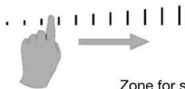
In order to select power, simply slide your finger over the slider, on the LED indication.
You can also access a certain level directly by using your finger to select the desired level.
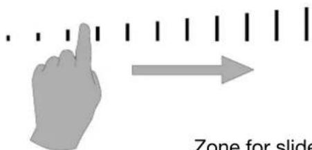
text_image
Zone for slideZone for slider control
5.3 Controlling the hob
5.3.1 Switch on and off
| Switching the hob on and off | |
| Switch on | |
| Press Ⓞ and continue to hold for 2 sec.The display will light up. | |
| Switch off | |
| Press ⏻ .Display goes out. | |
| Switching a cooking zone on and off | |
| Set up | Display |
| Select a cooking zone with the zone selection key. Slide from left to right on the slider (slider operation for power). | 0-9 |
| Switch off | |
| Select a cooking zone with the zone selection key. Slide from right to left on the SLIDER until the display shows 0 or H1. | 0H |
If there is no control input within 20 seconds, the electronics will return to the wait position.
5.3.2 Pan detection
This hob is equipped with an interactive control system that makes use of the hob even easier.
When you place a pan on the hob, it is automatically detected. You will also see a ☐ to show you which slider to use for the zone in question. The pan detection ensures optimum safety.
The induction hob does not work:
In case there is no pan on the cooking zone or if the pan is unsuitable for induction, it is impossible to put the power on and the symbol will appear on the display.
The operation is suspended when the pan is removed from the cooking zone during cooking. The symbol will appear on the display. The symbol will disappear when the pan is placed back onto the cooking surface. The cooking will then continue at the same power level as selected previously.
Switch off the cooking zone after use. The pan detection will no longer be active.
5.3.3 Indication of residual heat
After the cooking zone or hob has been switched off completely, the hob glass will still be warm, which can be seen by H. The H symbol disappears when the cooking zone glass can be handled without danger.
WARNING: As long as the residual heat indication remains active, the cooking zone(s) must not be touched and no heat-sensitive items should be placed on the cooking zone. Risk of fire and burns.
5.3.4 Power function and Super Power function
The Power function P and Super Power, increases the power rating of the selected cooking zone. If this function is activated, these cooking zones will be subjected to considerably higher power for 10 minutes. The Power function is designed to quickly heat large quantities of water, for pasta for example.
5.3.4.1 Power function
The Power function is available on all cooking zones.
| Switching Power on and off | |
| Switch on power Display | |
| Slide your finger over the slider to the end or push the end of the slider. | P |
| Switch off Power | 9-0 |
| Slide your finger over the slider. | |
5.3.4.2 Super Power function
The Super Power function is available for:
- 1851 / 1861 / 1861-g1 all zones.
- 1871 / 1881 / 1881-g1 the left-hand zones only.
Switching Super Power on and off
| Switch on power | Display |
| Slide your finger over the slider to the end or push the end of the slider. | P |
| Switch on Super Power | ,, 11 + P |
| Press the end of the slider again. | |
| Switch off Super Power | P-0 |
| Slide your finger over the slider. | |
| Switch off Power | 9-0 |
| Slide your finger over the slider. |
Management of maximum power:
The hob is divided into 2 separate heating groups.
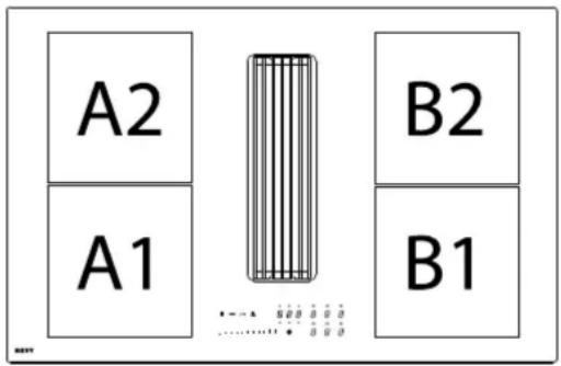
text_image
A2 B2 A1 B11851 /
1861 /
1861-g1
text_image
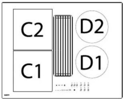
C2 C1 D2 D11871 /
1881 /
1881-g1
If this power limit is exceeded when switching to a high selected cooking heat or switching the power function on, the power management module reduces the cooking position of the relevant cooking zone. This cooking zone will first flash, and it is then automatically reduced to the maximum possible cooking heat
The maximum individual power for each zone is 3000 W. If simultaneous cooking is taking place on zones A1 & A2, B1 & B2 or C1 & C2, the power of 3700 W is divided between these 2 zones A1 & A2, B1 & B2 or C1 & C2.
| Type Cooking zone | in cm | Power (W) | |
| 185118611861-g1 | A1 | 24 x 21 | Normal: 2100Power: 2300Super Power: 3000 |
| A2 | 24 x 21 | ||
| B1 | 24 x 21 | ||
| B2 | 24 x 21 | ||
| 187118811881-g1 | C1 | 22 x 21 | Normal: 2100Power: 2300Super Power: 3000 |
| C2 | 22 x 21 | ||
| D1 | ∅ 175 | Normal: 1400Power: 2100 | |
| D2 | ∅ 175 | ||
| Power limit Display | |
| Selected cooking zone with Power function. | P |
| Power limit activated | 8 |
| [9] reduced to [8] and blinks. | |
In order to be able to make use of the maximum possible power for 2 zones at the same time, use a combination of zone A1 & A2, B1 & B2 or C1 & C2.
5.3.5 Timer function
The timer function allows all cooking zones to be used simultaneously for different periods of time (0 to 1H59 minutes) for each zone.
| Timer function | |
| Setting or changing the cooking time Display | |
| Select the power by sliding your finger over the slider. | 1-P |
| Select the timer | |
| Press the timer icon above the zone selection key for the required cooking zone. | L |
| Reduce the time | 0 0 1- |
| Press [-] on the timer. | 1 5 9... |
| Increase the time | 0 6 0- |
| Press [+] on the timer. | 0 5 9... |
After a few seconds the LED ☑ no longer flashes. The time has been selected and the countdown has begun.
| Switch off the timer function | |
| Select the timer Display | |
| Press the timer icon above the zone selection key for the required cooking zone. | |
| Stop the timer | |
| Keep pressing [-] on the timer until the timer displays 000. | 000 |
After a few seconds the LED ☐ no longer flashes. The timer is now deactivated.
If different timers are to be activated on multiple zones, this operation must be repeated several times. The activated timer indication no longer lights up above the relative cooking zone.
The timer can also be used as an independent cooking alarm without selecting a cooking zone. If the hob is to be switched off, the independent cooking timer will continue until the end of the set time.
| Using the timer without cooking | |
| Timer without cooking Display | |
| Switch on the hob.Press 1 for 2 seconds. | |
| Select the timer | 000 |
| Press the timer indicator [000]. | |
| Reduce the time | 060- |
| Press [-] on the timer. | 059... |
| Increase the time | 001- |
| Press [+] on the timer. | 002... |
After a few seconds the timer display stops flashing. The time is selected and counting down starts.
Turn off automatically at the end of the cooking time
As soon as the selected cooking time is up, the display will flash [000], a beep will be heard. To stop the audible signal and the flashing, press [-] or [+] on the timer.
5.3.6 Programming auto heat up
All cooking zones are equipped with an auto heat up function. The cooking zone will initially operate at full power for a certain amount of time before automatically reducing to the selected power level.
| Programming auto heat up | |
| Activating auto heat up Display | |
| Slide your finger over the slider to (for example) 6 and hold for 3 seconds. | 6 A |
| Switching auto heat up off Display | |
| Slide your finger over the slider 0 to 9. | 0-9 |
| Auto heat up table | |
| Set value for cooking position | Auto heat up function Time (min:sec) |
| 1 | 0:40 |
| 2 | 01:12 |
| 3 | 02:00 |
| 4 | 02:56 |
| 5 | 04:16 |
| 6 | 07:12 |
| 7 | 02:00 |
| 8 | 03:12 |
| 9 | --:-- |
5.3.7 Stop & Go function
This function temporarily interrupts the activity of the hob and allows a restart with the same settings.
| Turning Stop & Go on and off | |
| Switching on Display | |
| Press || for 2 seconds until it blinks. | || |
| Switching off | |
| Press || for 2 seconds until it blinks.Select a cooking zone with the zone selection key. | 0-9 |
5.3.8 Recall function
After turning the hob off ⒶIt is possible to recall the last selected settings: (this up to a maximum of 10 seconds).
– State of all cooking zones (power).
– Minutes and seconds of the programmed cooking zones by the timers.
– Automatic cooking function.
- Keep warm function.
The recall procedure is as follows:
- Push the control key ^1 for 2 seconds.
- Push before the flashing stops.
The previous settings are now active again.
5.3.9 Keep warm function
This function makes it possible to automatically reach and maintain a temperature of 70^ C.
This prevents pans overflowing or your food sticking to the bottom of the pans.
| Switching the keep warm function on and off | |
| Switching on Display | |
| Select the zone using the zone selection button. Press ☐. | ☐ |
| Switching off | |
| Select the zone using the zone selection button. Press ☐. | ☐ |
The maximum duration of the keep warm function is 2 hours.
5.3.10 Flexzone
This function allows on models:
- 1851 / 1861 / 1861-g1:
linking the 2 left and the 2 right flex zones to form 2 large zones.
- 1871 / 1881 / 1881-g1:
linking the 2 left flex zones to form 1 large zone.
This function can be activated manually, or automatically when a large pot/pan be placed on the cooking surface.
| Flexzone | |
| Manual activation Display | |
| Simultaneously press the 2 zone selection keys of the 2 flex zones A1 & A2, B1 & B2 or C1 & C2 to be shared. | 0 7 |
| Automatic activation | 7 |
| Place a pot on the zones A1 & A2, B1 & B2 or C1 & C2. | |
| Increase the power | 0-9 |
| Slide your finger over the left slider until you reach the desired power level, both flex zones display the chosen power. | |
| Switch Flexzone off | 0 |
| Simultaneously press the 2 zone selection keys of the 2 combined zones. | |
5.3.11 Grill function
This special cooking function optimises heating and warming in a cast iron pot/grill plate. This will ensure improved results of the food you are cooking. The cooking zones A1 & A2, B1 & B2 or C1 & C2 will be automatically shared using the Flexzone.
| Grill function: | |
| Activate Display | |
| Select a cooking zone using the zone selection key. Press GRILL | ≡ Ω |
| Increase the power | |
| Slide your finger over the left slider until you reach the desired power; both zones display the chosen power. | ...... |
| Switch grill off | |
| Select a cooking zone using the zone selection key. Press GRILL | 0 |
5.3.12 Locking the controller
To avoid a hob selection being changed, during cleaning for example, the controller must be locked (except the on/off button).
| Locking: | |
| Lock Display | |
| Press the —0 for 2 seconds. The symbol now lights up brightly. | —0 |
| Unlock | |
| Press the —for 2 seconds. The symbol now lights up normally. | —0 |
6EXTRACTOR
6.1 Control panel
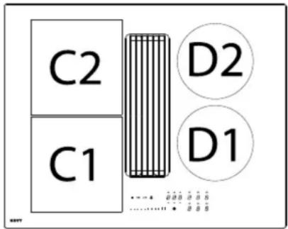
text_image
|| GRILL =0 ☑ 8 8 8 8 8 8 - - - ⑤ ⑤ ⑤ . . . . . . . . . . . . . . . . . . . . . . . . . . . . . . . . . . . . . . . . . . . . . . . . . . . . . . . . . . . . . . . . . . . . . . . . . . . . . . . . . . . . . . ① 8 8| Extractor control | |
| On/off control key for extractor | 1 |
| Zone selection key | 8 |
| Timer time indication and selection | + + + + 0 0 0 - - - |
| Timer indicator | L |
| Slider control | |
6.2 Control keys and slide operation
The device is equipped with touch control keys with which you can set the various functions. Touching the control key operates the function. Activating a function will cause a light, reading and/or sound signal to be displayed.
WARNING: Do not push multiple control keys simultaneously during normal use.
In order to select power, simply slide your finger over the slider, on the LED indication.
You can also access a certain level directly by using your finger to select the desired level.
text_image
Zone for sZone for slider control
6.3 Extraction mode
1851 / 1871 &
1861-g1 / 1881-g1 (optional setting) ^1
The air drawn in is first cleaned by the grease filters before being expelled outside. This can be done by making use of ducting connected between the appliance and a wall outlet grille.
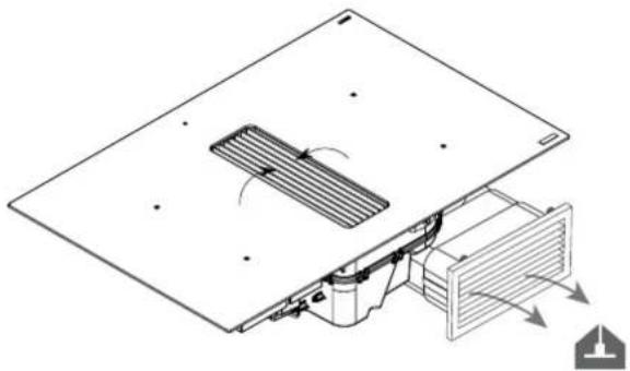
natural_image
Technical diagram of an air duct system with airflow arrows indicating movement (no text or symbols)Ensure adequate air supply to the kitchen for the system to work efficiently.
6.4 Recirculation mode
1861 / 1881 &
1861-g1 / 1881-g1 (default setting) ^1
The air drawn in is first cleaned by the grease filters. The scents are then removed by the recirculation filter before re-entering the kitchen.
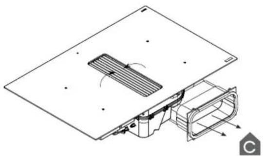
natural_image
Technical line drawing of a mechanical component with internal structure and mounting holes (no text or symbols)Provide adequate ventilation in the kitchen for optimal efficiency of the recirculation system.
6.5 Extractor controls
6.5.1 Switch on and off
| Extractor | |
| Increase extraction power Display | |
| Press the zone selection button of the extractor.Slide over the SLIDER. | 0 - 9 |
| Reduce extraction power | |
| Press the zone selection button of the extractor.Slide over the SLIDER. | 9 - 0 |
| Switch off extractor | |
| Press the zone selection button of the extractor.Slide over the SLIDER. | 0 |
6.5.2 Automatic extraction
This function automatically adjusts the extraction power depending on the power used of the cooking zone(s). When this function is active when switching off the appliance, it is automatically activated when switching on again.
| Automatic extraction | |
| Switch on automatic extraction | A |
| Press the zone selection button of the extractor and keep pressed for 3 seconds. | |
| Switch off automatic extraction | O |
| Press the zone selection button of the extractor and keep pressed for 3 seconds. | |
Tip: the extraction power can be changed quickly by sliding over the SLIDER.
This action temporarily halts the automatic extraction. The automatic extraction is reactivated the next time the appliance is switched on.
6.5.3 Automatic run-on function
The appliance is equipped with an automatic run-on function.
Speed 1 or, in automatic mode, is displayed.
| Automatic extraction | |
| Switch on delay function | R_or 1 |
| Press ⏻ | |
| Switch off delay function | LED goes out |
| Press ⏻ again. | |
Run-on function extraction mode (1851 / 1871) ^1
This function starts up after the cooking stops. With it, all the last cooking vapours are extracted from the kitchen for a pre-set time by the extraction hood at low extraction power. The run-on time is by default set to 10 minutes in extraction mode. It is advisable always to carry out this function completely. After the end of the run-on time, the extractor switches off automatically.
The run-on function can be switched off manually by pressing the button ① again.
The 1861-g1 and 1881-g1 ^1 models can also be switched to extraction mode.
Refer to section 9.2.5 for more information.
Run-on function recirculation mode (1861 / 1881 & 1861-g1 / 1881-g1) ^1
This function starts up after the cooking stops. With it, all the last cooking vapours are extracted from the kitchen for a pre-set time by the extraction hood at low extraction power. With recirculation, the recirculation filters are dried, and the run-on time is by default set to 30 minutes. It is advisable always to carry out this function completely. After the end of the run-on time, the extractor switches off automatically.
The run-on function can be switched off manually by pressing the button again, but this is advised against to avoid affecting the service life and operation of the recirculation filter.
7CLEANINGINDICATIONS
7.1 Grease filter cleaning indicator
The grease filter should be cleaned after 20 hours of cooking. This is automatically indicated by the appliance.
When the appliance is switched on and the extraction power is set to 0, the time remaining before cleaning the filter can be read off from the timer display.
After 20 hours of cooking, GrE 00h will appear on the timer display.
| Grease filter | |
| Grease filter remaining time Display | |
| Press the zone selection button of the extractor. Press ☐ above the zone selection button of the extractor. The remaining time is indicated. | GREHHh |
| Resetting the grease filter indicator | |
| Press the zone selection button of the extractor. Press ☐ above the zone selection button of the extractor. Press ☐ for 5 seconds until it changes to 20h. Then press ☐ again for 5 seconds to confirm. | 20h |
Follow the cleaning instructions set out in the chapter 9 Cleaning and maintenance.

7.2 Recirculation filter replacement indicator 1861 / 1881 & 1861-g1 / 1881-g1 (in recirculation mode) ^1
The usage time of the recirculation filter depends on the type of recirculation filter used. After the usage time has expired, it is recommended to replace the recirculation filter. The message that replacement is necessary is indicated by the appliance itself. After the usage time has expired, ChR 00h appears on the timer display.
| Recirculation filter | |
| Recirculation filter remaining time Display | |
| Press the zone selection button of the extractor. | |
| Press 2x above the zone selection button of the extractor. | ChR00h |
| The remaining time is indicated. | |
| Resetting the recirculation filter indicator | |
| Press the zone selection button of the extractor. | 150h |
| Press 2x above the zone selection button of the extractor. | 300h |
| Press 00h for 3 seconds until the timer is reset. | 450h |
| Then press again for 3 seconds to confirm the reset timmer value. | |
Follow the replacement instructions set out in the chapter 9 Cleaning and maintenance.

8COOKINGADVICE
Quality of the pots and pans
Suitable cookware, pots and pans include: steel, enamelled steel, cast iron, stainless steel with magnetic base, aluminium with magnetic base ( ± 100mm min). Unsuitable pans include: aluminium and stainless steel without magnetic base, copper, brass, ceramics, porcelain. The manufacturers will state whether their products are suitable for induction.
In order to ensure your pans are suitable:
Pour a little water in a pan and place it on an induction cooking zone set to 9. The water should be hot within a few seconds.
- Hold a magnet to the base of the pan. The magnet should stick.
Some cooking pots hum when they are placed on an induction cooking zone. This does not mean the device is faulty, and it will not affect operation. This noise decreases when you adjust the power.
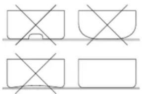
natural_image
Four geometric shapes with intersecting lines, no text or symbols presentLil the pans up when you want to move them to avoid stains and scratches.
Ensure that the outside of the pan is dry and clean. Make sure there are no food residues or other particles on the hob or underneath the cookware, as these may cause scratches or damage.
As often as possible, prepare meals with the pan lid on.
Dimensions of the cooking pans
The cooking zones can (to a certain extent) automatically adapt to the diameter of the pan. The base of the pan must have a minimum diameter ( ± 9cm) for working with the selected cooking zone. Place the pan in the middle of the cooking zone in order to optimise the energy transfer. The bottom of the cooking pan must cover as much of the cooking zone as possible. If the diameter of the pan is much larger than the zone, this will not result in an optimal cooking result.
Only the surface of the pan above the induction coil will then generate the heat. The rest of the surface that is not above the induction coil will receive heat via conduction through the pan surface.
Therefore, if the pan is much larger than the cooking zone, it advised to set the cooking zone to a slightly lower level to allow the heat to be divided up more evenly.
Examples of power control
(The values indicated below are only indicative)
| Application | Display | |
| MeltingWarming up | - Sauces, butter,chocolate, gelatine- Pre-prepared meals | 1-2 |
| RisingDefrosting | - Rice pudding andpre-prepared meals- Vegetables, fish, frozenproducts | 2-3 |
| Steaming | - Vegetables, fish, meat | 3-4 |
| Water | - Boiled potatoes, soups,pasta- Fresh vegetables | 4-5 |
| Simmering | - Meat, liver, eggs, grilledsausages- Goulash, rolled meat,black/white pudding | 6-7 |
| CookingRoasting | - Potatoes, fritters,flat biscuits | 7-8 |
| RoastingBringingto cookingtemperature | - Steaks, omelettes- water | 9 |
| Cooking | - Bringing large quantities of water to the boil | P+11 11 |
9CLEANINGAND MAINTENANCE
Follow all instructions as described in the section "Using the appliance" and as mentioned in the separate booklet "Safety instructions" supplied with the appliance and listed on our website www.novy.com.
Before cleaning, check the cooking plate has been fully switched off and the glass above the cooking zones has cooled down.
Follow the cleaning instructions below for a long life and optimum functioning of the device.
9.1 Maintenance of the hob
First let the device cool down, otherwise there is a risk of burns.
Never use "steam" or "pressure" equipment.
Never use objects that could damage the vitro-ceramic glass such as an abrasive sponge, abrasive cleaning liquid or aggressive cleaning agents.
Cleaning the glass of the hob
Clean the glass surface of the hob after each use to prevent cooking residues from burning in and damaging the surface.
Step-by-Step Cleaning Instructions
- Allow the surface to cool down completely.
- Do not apply cleaning agents to a warm hob – this may cause discolouration.
Use a damp, soft cloth or a non-scratch, non-abrasive sponge.
Clean using a cleaner specifically designed for ceramic glass.
Always follow the manufacturer's instructions for the cleaning product.
Dry the glass with a microfibre cloth to achieve a streak-free, glossy finish.
Unsuitable Cleaning Products
Avoid using the following products, as they may damage the surface:
– Undiluted washing-up liquid
– Dishwasher detergents
- Abrasive cleaning agents
Harsh or corrosive cleaners (such as oven sprays or stain removers)
- Scouring sponges
– High-pressure or steam cleaning equipment

Always use mild products and suitable trials to extend the life of your hob and nt damage.

Ensure cookware bases are clean to scratches and burnt-in residues on the surface.
In case of stubborn stains
Heavy contamination and stains (limescale stains, pearl-like shiny spots) are best removed while the hob is still warm. For this apply common cleaning agents and cleaning methods.
If this is still not sufficient, you can follow these steps:
- Use a glass scraper to carefully remove as many stains as possible.
- If stains remain, apply a mild alkaline cream cleaner and leave it to work for 10 minutes.
- Then rub with a non-abrasive sponge or cloth to loosen the stains.
- Finally, dry the glass with a microfibre cloth for a streak-free, shiny finish.
Boiled-over food should first be soaked with a wet cloth; the contamination residues should then be removed with a glass scraper that is specially designed for ceramic hobs. After this, clean the hob as described under “Cleaning the glass of the hob”.
Burnt-on sugar and melted plastics are best removed immediately – while still hot – with a glass scraper. After this, clean the hob as described under “Cleaning
the glass of the hob". Grains of dirt/sand may fall on the cooking plate while peeling potatoes or washing vegetables and may cause scratches when moving the pans. Therefore, ensure there are no grains left on the surface.
Discolouration of the hob does not have any influence on the operation or strength of the vitro-ceramic. It is not a form of damage to the hob, but it is a result of residues that have not been removed and have therefore burnt-in.
Shiny spots occur as a result of wear caused by the base of the pans, in particular when using cooking pans with an aluminium bottom or when using the wrong cleaning agents. These can only be removed with great difficulty using common cleaning agents. If necessary, repeat the cleaning several times.
Due to the use of aggressive cleaning agents and scratching caused by the pan bases, the glass surface is rubbed off over the course of time, leaving dark stains.
Do not use the cooking plate as a table top or for putting utensils on.
Always lift up the pans/pots and do not slide them along the glass plate.
9.2 Maintenance of the extractor
9.2.1 Remove the inlet grille
Do not use any objects that could damage the inlet grille, such as potscourers, scouring agents or aggressive cleaning agents.
First switch off the hob and the delay before removing components from the extractor.
- Press on the right of the inlet grille until it tilts.
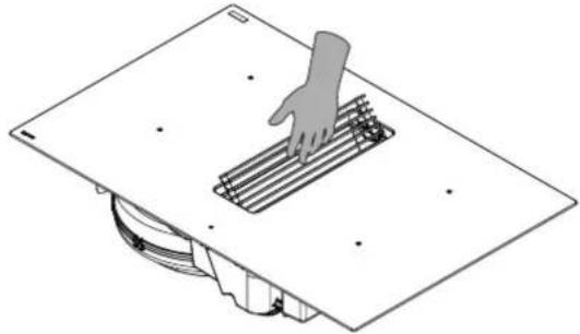
natural_image
Diagram of a hand pressing a grid on a workbench, with no visible text or symbols- Grasp the inlet grille and put it aside safely on the kitchen worktop.
Do not place the inlet grille on the hob glass to avoid scratches. Do not place the inlet grille on a hob that has been switched on to prevent it heating up.
9.2.2 Replace inlet grille
Take care that the recirculation filter and grease filter have first been placed in the appliance before replacing the inlet grille.
Grasp the inlet grille and insert it in the centre of the extraction opening in line with the position marks.
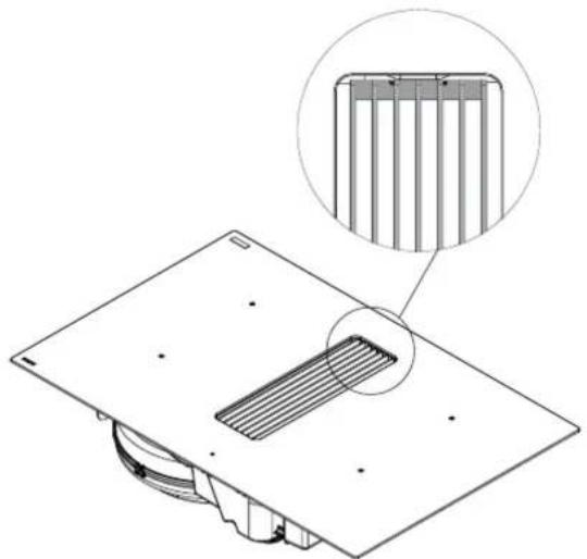
natural_image
Technical diagram of a mechanical component with a magnified inset showing internal structure (no text or symbols)9.2.3 Cleaning the grease filter
When the grease filters need to be cleaned, this is indicated by the grease filter cleaning indicator (see 7.1).
Accessing the grease filter
- Remove the inlet grille (see 9.2.1).
- Grasp the grease filter by the grips and lift it out of the extraction opening.
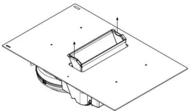
natural_image
Technical line drawing of a mechanical assembly with a rectangular component and mounting base (no text or symbols)Cleaning the grease filter
The metal grease filter can be cleaned by hand or in a dishwasher. We recommend cleaning the grease filter by hand.
Cleaning the filter by hand:
Immerse the filter in a solution of boiling water to which a liquid detergent has been added.
Do not use aggressive, acidic or alkaline cleaning products.
- Use a brush for cleaning.
- Then rinse the filters with warm water under a tap and allow them to dry.
Cleaning the filter in a dishwasher:
- Use a customary dishwasher detergent.
Do not put the saturated grease filters together with crockery in the dishwasher.
Select a programme with a low temperature (maximum 65^ C).
– After cleaning allow the filter to drain.
WARNING: When cleaning in a dishwasher the filter may discolour as a result of the salt content. This does not affect its operation.
WARNING: If the instructions above are not carried out, serious soiling can cause a fire hazard.
After cleaning
- Using the grips, replace the grease filter in the right direction in the extraction opening.
- Replace the inlet grille in the extraction opening.
- Reset the grease filter indicator (see 2.1).
Y can obtain a new grease filter from a dealer which you can find on the Novy website.
• 1851 / 1861: Article number 99003
• 1871 / 1881: Article number 99005
• 1861-q1: Article number 99003
• 1881-q1: Article number 99005
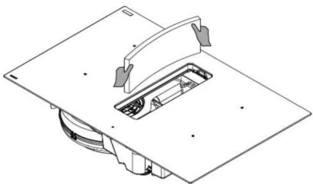
9.2.4 Replacing the recirculation filter
1861 / 1881 &
1861-g1 / 1881-g1 (in recirculation mode)
- Remove the inlet grille (see 9.2.1).
- Remove the grease filter (see 9.2.3).
- Grasp the recirculation filter, tilting it forwards.
Fold both corners over and remove the recirculation filter from the extraction opening.
natural_image
Technical line drawing of a mechanical assembly with no visible text or symbolsAfter replacing:
– Fold back the corners of the new recirculation filter and replace it in the frame through the extraction opening.
- Press the filter right up against the frame.
- Using the grips, replace the grease filter in the right direction in the extraction opening.
- Replace the inlet grille in the extraction opening.
replaced by the same recirculation filter as supplied as standard:
- Reset the recirculation filter replacement indicator (see 7.2).
- If replaced by a different recirculation filter is supplied as standard:
- Adjust the recirculation timer of the filter to set the correct lifespan (see 9.2.5).
- Reset the recirculation filter replacement indicator (see 7.2).
You can obtain a new recirculation filter from a dealer which you can find on the Novy website:
| Recirculation filter | |||
| Artikel M | Monoblock filter Pure | Pro Pure Pro Finesse | |
| 1861 980 | 02 1861560 (default) | 1861570 | |
| 1881 980 | 05 (default) - | - | |
| 1861-g1 | 98002 (default) | 1861560 | 1861570 |
| 1881-g1 | 98005 (default) - | - | |
9.2.5 Setting the recirculation filter usage time (only for 1861-g1 / 1881-g1) ^1
The 1851 and 1871 ^1 are suitable for external extraction only and are supplied without recirculation filter.
The 1861 and 1881 ^1 are suitable for recirculation only and are supplied as standard with a recirculation filter:
- 1861 ^1 : with a usage lifespan of 300 hours.
- 1881 ^1 : with a usage lifespan of 450 hours.
The 1861-g1 and 1881-g1 ^1 models are suitable for recirculation and come equipped with a recirculation filter with a lifespan of 450 hours.
On these models, it is possible to switch from recirculation mode to extraction mode.
Refer to the configuration procedure in the installation instructions.
You can buy a new recirculation filter from your dealer which you can find on the Novy website. You will find a selection of recirculation filters suitable for this appliance on the Novy website.
Then reset the indicator to set the usage time to zero (see 7.2).
Configuration procedure:
For modifying the recirculation timer when using a different recirculation filter.
This procedure only applies to the 1861-g1 & 1881-g1 ^1 .
The 1861-g1 & 1881-g1 ^1 are suitable for both extraction to outside and recirculation.
In the factory, the unit is set to recirculation.
For use with extraction to outside, the setting must be adjusted (see procedure in the installation instructions).
Please note: For the 1851, 1861, 1871 and 1881^1 , this procedure is not necessary, these models are set correctly by default.
1) Switch on the cooktop by pressing the button.
2) Switch the cooktop off again within 3 seconds by pressing the ⏻ button again.
3) Press and hold the || button.
4) A 5 now appears in each display.
5) Activate the user menu by quickly (within 2 seconds) pressing the displays with the symbol 5 with one finger of the other hand in this order:
- 1 (front left)
- 2 (rear left)
• 3 (rear right) - 4 (front right)
- Then release the || button.
Please note: If there is a double beep, there is an operating error. Restart the procedure from step 3.
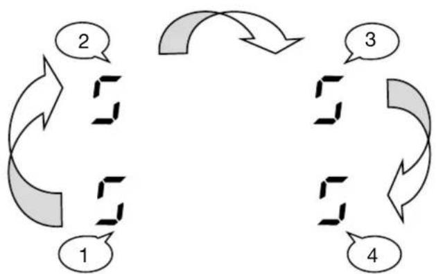
flowchart
graph TD
    A["1"] --> B["2"]
    B --> C["3"]
    C --> D["4"]
    D --> A
    style A fill:#f9f,stroke:#333
    style B fill:#ccf,stroke:#333
    style C fill:#cfc,stroke:#333
    style D fill:#fcc,stroke:#333
6) In display 2, the indication changes from U to 1, indicating that the user menu is active.
7) Change the configuration for a different recirculation filter:
- Press display 1 first to activate the configuration.
- Use the SLIDER to change the setting from ex. 3 (Monoblock filter) to 2 (Pure Pro).
- Confirm the change by pressing and holding the ⏻ button for 2 seconds.
The appliance is now set to a different type of recirculation filter with a different lifespan. Then reset the usage time by setting the counter to zero (see 7.2).
| Configuration | Application | Recirculation-filter | Mode | Grease timer (h) | Recirculation timer | Run-on time (min.) |
| 0 | 1851 (default), 1861-g1 (optional) | - E 20 - 10 | ||||
| 1 | 1861 & 1861-g1 (optional) | Pure Pro Finesse | R | 20 | 150h | 30 |
| 2 | 1861 (default), 1861-g1 (optional) | Pure Pro | R | 20 | 300h | 30 |
| 3 | 1861 (optional), 1861-g1 (default) | Monoblock filter | R | 20 | 450h | 30 |
| 5 | 1871 (default), 1881-g1 (optional) | - E 20 - 10 | ||||
| 6 | 1881 & 1881-g1 (optional) | Pure Pro Finesse | R | 20 | 150h | 30 |
| 7 | 1881 (default), 1881-g1 (optional) | Pure Pro | R | 20 | 300h | 30 |
| 8 | 1881 (optional), 1881-g1 (default) | Monoblock filter | R | 20 | 450h | 30 |
* Mode: E = extraction, R = recirculation
8) Press the ⏻ button for 2 seconds to confirm the configuration.
10TROUBLESHOOTINGMINOR FAULTS
10.1 Messages on the hob
| Code | |
| U | there is no cooking pan on the cooking zone.the cooking pan is not suitable for induction.the diameter of the bottom of the cooking pan is too small when compared to the cooking zone. |
| U | See Chapter 5.3.9 Keep warm function |
| E | – The electronic system is disrupted.– Disconnect and reconnect the hob.– Call the after-sales service. |
| II | See Chapter 5.3.7 Stop & Go function |
| (Er03) | The controller keys are covered by liquid or an item. The symbol will disappear as soon as the keys are released or cleaned. |
| E2 | The hob has overheated, leave to cool, then switch back on. |
| E8 | The fan air supply is blocked.Unblock it. |
| U400 | The hob has not been properly connected to the network. Check the connection. |
| (Er47) | Problem in the device's internal bus system. |
If one of these error messages remains visible, you can contact the after-sales service.
The hob or the cooking zone does not work:
the hob has been poorly connected to the electrical power supply.
– the safety fuse has blown.
– check the locking key has been enabled.
the touch control keys have been splashed with water or fat.
– there is an object on the touch control keys.
A single zone or all zones are not working:
– the safety device has been operated.
this shall engage when a cooking zone has been left on unintentionally.
the safety shall also engage when one or more touch control keys are covered.
- a pan is empty and the base has overheated.
- the hob also has an automatic power reducer and automatic shut-down in the event of overheating.
The fan continues to operate after the hob has switched off:
this is not a defect, the fan is protecting the electronic equipment.
– the fan will stop automatically.
The automatic cooking controller does not seem to be working:
- the cooking zone is still warm.
the maximum cooking level has been selected [9].
the cooking level was selected using the control key [ - ].
10.2 Messages at the extraction
The cooker hood does not extract well. What can be the cause of this problem?
Check that the recirculation filter and grease filter have been correctly inserted with the inlet grille.
Check the grease filter. Follow the cleaning indication. On average, the filter must be cleaned every two weeks to ensure the extraction works correctly.
- Check the air supply in the house. As soon as the cooker hood is switched on, make sure that air is supplied by opening the grates in the windows or by opening a window.
10.3 Service
In case of a malfunction, please do not hesitate to contact our after sales service:
www.novy.com/contact.
Choose your country.
For a proper and prompt handling, the after sales service needs to know the type of your device. This information can be found on sticker at the bottom of the device.
OVERVIEWFUNCTIONS NOVY EASY
Indication extractor
① On/off control key for the extractor
8 Extractor selection key
Slider control
8 8 8 Timer time indicator
+ + + Timer time control keys
Indication hob
① On/off control key for the hob
8 8 8 Timer time indicator
+ + + Timer time control keys
II Stop & Go control key
8 Power level indication/zone selection key
Flexzone indication
Timer indicator
Keep warm function key
GRILL Grill function key
Slider control
Lock key
Hob control
Switch hob on/off
ON - Press ① and hold for 2 seconds. LED will light up.
OFF - Press Ⓐ. LED goes out.
Set the power control
MORE - Slide your finger over the slider (Power Control).
Less - Slide your finger over the slider to ☐.
Switching Power on and off
ON - Slide your finger over the slider to the end - [P].
OFF- Slide your finger over the slider [900].
Switching Super Power on and off
ON - Switch power on.
Press the end of the slider again.
OFF- Slide your finger over the slider [900].
Power limit activated
[9] will be reduced to [8] and [8] blinks.
Stop & Go function
ON - Press II for 2 seconds until it blinks.
OFF - Press II for 2 seconds until it blinks.
Select a cooking zone with the zone selection key.
Select the timer
Press 📊 above the zone selection key.
Reduce the time
Press [-] on the timer.
Increase the time
Press [+] on the timer.
Switch off the timer function
Press 📊 above the zone selection key.
Keep pressing [-] on the timer until the timer displays 000.
Using the timer without cooking
Switch on the hob.
Press ⏻ for 2 seconds.
Press the timer indicator [000]. Adjust the duration using [-] or [+].
Programming auto heat up
ON - Slide your finger over the slider, continue pressing on the desired power for 3 seconds.
OFF - Slide your finger over the slider.
Keep warm function
IN - Press 📋.
OFF - Press 📋.
Operate Flexzone manually
ON - Press the 2 zone selection keys at the same time.
OFF - Press the 2 zone selection keys at the same time.
Operate Flexzone automatically
ON - Place a pan on the front and rear zone.
OFF - Press the 2 zone selection keys.
Grill function
ON - Press GRILL.
Off - Press GRILL.
Extractor control
Set extraction power regulator
HIGHER - Slide over the SLIDER.
LOWER - Slide to 0 over the SLIDER.
Automatic extraction power regulator
ON - Press the zone selection button of the extractor and keep pressed for 3 seconds.
OFF - Press the zone selection button of the extractor and keep pressed for 3 seconds.
Novy nv reserves the right at any time and without reservation to change the structure and the prices of its products.
NOVY nv
Noordlaan 6
B - 8520 KUURNE
Tel. +32 (0)56 36 51 00
info@novy.com
www.novy.com