LWZ 130 E-W - Central ventilation STIEBEL ELTRON - Free user manual and instructions
Find the device manual for free LWZ 130 E-W STIEBEL ELTRON in PDF.

| Product type | Mechanical ventilation with heat recovery (balanced ventilation) |
| Brand | Stiebel Eltron |
| Model | LWZ 130 E-W |
| Dimensions (H x W x D) | 240 x 527 x 1264 mm |
| Weight | 18 kg |
| Power supply | 230 V, 50 Hz, 1/N/PE, protection B16A |
| Power consumption (without preheating) | 105 W |
| Power consumption (with preheating) | 1150 W |
| Airflow rate | 50 to 180 m³/h |
| Heat recovery efficiency | Up to 89% |
| Energy efficiency class | A |
| Main functions | Heat recovery, summer bypass, frost protection, humidity control, programming mode, touch control |
| Maintenance | Filter replacement (G4 and F7) at least every 12 months, initial check after 3 months |
| Safety | Frost protection, ventilation stop, window contact, anti-condensation device |
| Spare parts | Filters FMS G4-10, FMK F7-2, optional condensate pump (ref. PK 130) |
| Ambient conditions | Room temperature 2 to 35 °C, outdoor temperature -15 to 40 °C |
| Protection rating | IP20 |
| Connections | Air ducts diameter 125 mm, condensate drain diameter 22 mm |
| Control unit | Wired touch screen, connected via I²C bus (max. length 20 m) |
Frequently Asked Questions - LWZ 130 E-W STIEBEL ELTRON
User questions about LWZ 130 E-W STIEBEL ELTRON
0 question about this device. Answer the ones you know or ask your own.
Ask a new question about this device
Download the instructions for your Central ventilation in PDF format for free! Find your manual LWZ 130 E-W - STIEBEL ELTRON and take your electronic device back in hand. On this page are published all the documents necessary for the use of your device. LWZ 130 E-W by STIEBEL ELTRON.
USER MANUAL LWZ 130 E-W STIEBEL ELTRON
BEDIENUNG UND INSTALLATION OPERATION AND INSTALLATION UTILISATION ET INSTALLATION GEBRUIK EN INSTALLATIE USO E INSTALLAZIONE OBSLUHA A INSTALACE OBSLUHA A INŠTALÁCIA OBSŁUGA I INSTALACJA KEZELÉS ÉS TELEPÍTÉS UPRAVLJANJE IN MONTAŽA
Zentrales Lüftungsgerät mit Wärmerückgewinnung | Central ventilation appliance with heat recovery | Ventilation mécanique contrôlée double flux | Centraal ventilatietoestel met warmteterugwinning | Unità di ventilazione centralizzata con recupero di calore | Centrální větrací přístroj s rekuperací tepla | Centrálna vetracia jednotka s rekuperáciou tepla | Centralne urządzenia wentylacyjne z odzyskiem ciepta | Hővisszanyerős központi szellőztetőberendezés | Prezračevalna naprava z izkoriščanjem odpadne toplote
natural_image
Technical line drawing of a mechanical housing or enclosure with internal components and mounting holes (no text or symbols)BESONDERE HINWEISE
BEDIENUNG
natural_image
Four technical floor plan views of a room with furniture and fixtures, no visible text or symbolsnatural_image
Technical line drawing of a mechanical device with internal components and mounting holes (no text or symbols)natural_image
Technical line drawing of two vehicle components connected by pipes, with a cross symbol indicating a specific part (no text or labels present)natural_image
Technical line drawing of a mechanical device with circular components and a rotating knob (no text or symbols)natural_image
Mechanical assembly diagram showing four stages of a pipe fitting with arrows indicating movement (no text or symbols)natural_image
Technical line drawing of a mechanical housing or enclosure with two circular components mounted inside (no text or symbols)natural_image
Technical line drawing of a mechanical assembly with a cylindrical component inserted into a housing (no text or symbols)natural_image
Diagram of a screwdriver inserted into a device component, showing tool movement (no text or symbols)natural_image
Technical diagram of a device housing with an inset close-up showing internal components (no text or symbols)1 Unterputzdose
natural_image
Technical diagram of a mechanical device with internal components and an inset close-up view (no text or symbols)1 Keil
VORSICHT Verletzung
- General information 38
1.1 Safety instructions 38
1.2 Other symbols in this documentation 38
1.3 Information on the appliance 39
1.4 Standardised output data 39
1.5 Units of measurement 39 - Safety 39
2.1 Intended use 39
2.2 General safety instructions 39
2.3 Test mark 39 - Appliance description 40
3.1 Frost protection 40
3.2 Bypass mode 40 - Settings 40
4.1 Programming unit 40
4.2 Parameters adjustable from the home screen ____ 41
4.3 Menus 42
4.4 Switching off the appliance 45 - Maintenance, cleaning and care 45
5.1 Replacement filters 45
5.2 Filter inspection and replacement 45 - Troubleshooting 46
INSTALLATION
- Safety 47
7.1 General safety instructions 47
7.2 Instructions, standards and regulations 47
7.3 Operation of the appliance in buildings with combustion equipment 47
- Appliance description 48
8.1 Standard delivery 48
8.2 Accessories 48
- Preparation 48
9.1 Storage 48
9.2 Installation site 48
9.3 Transport 50
- Installation 50
10.1 Mounting the appliance 50
10.2 Connecting the condensate drain hose 51
10.3 LWZ 130 E-W: Pipe bend with condensate drain ____ 52
10.4 Air ducts 52
10.5 Programming unit 53
10.6 Electrical connection 54
10.7 Overflow apertures 56
10.8 LWZ 130 E-W: Extract air filter 56
- Commissioning 56
11.1 Initial start-up 56
11.2 Recommissioning 57
11.3 Appliance handover 57
- Settings 57
12.1 Menus 57
12.2 Direct selection parameters 60
- Shutting down the system 60
- Maintenance 61
- Troubleshooting 62
- Disposal 62
- Specification 63
17.1 Dimensions and connections 63
17.2 Fan diagram 65
17.3 Wiring diagram 66
17.4 Data table 67
GUARANTEE
ENVIRONMENT AND RECYCLING
FILTER INSPECTION LOG
SPECIAL INFORMATION
- The appliance may be used by children over 8 years of age and persons with reduced physical, sensory or mental capabilities or a lack of experience and expertise, provided that they are supervised or they have been instructed on how to use the appliance safely and have understood the potential risks. Children must never play with the appliance. Cleaning and user maintenance must not be carried out by children without supervision.
- Observe all applicable national and regional regulations and instructions.
- The appliance is not approved for outdoor installation.
- You must not install the appliance in safety zones 0, 1 and 2. The safety zones are defined in the IEC 60364-7-701 standard.
- Maintain the minimum clearances. See chapter "Preparations / Installation site".
- Fix the appliance in position as described in chapter "Installation / Preparations".
- The connection to the power supply must be in the form of a permanent connection. Ensure the appliance can be separated from the power supply by an isolator that disconnects all poles with at least 3 mm contact separation.
- Observe the fuse protection required for the appliance (see chapter "Specification / Data table").
- For the power cable, connections and connecting cables to external control equipment, observe chapter "Electrical connection" and the wiring diagram in chapter "Specification".
- The power cable must only be replaced (for example if damaged) by a qualified contractor authorised by the manufacturer, using an original spare part.
OPERATION
1. General information
The chapters "Special information" and "Operation" are intended for appliance users and qualified contractors. The chapter "Installation" is intended for qualified contractors.

Notice
Read these instructions carefully before using the appliance and retain them for future reference. Pass on the instructions to a new user if required.
1.1 Safety instructions
1.1.1 Structure of safety instructions

SIGNAL WORD Type of risk Here, possible consequences are listed that may result from failure to observe the safety instructions.
▶ Steps to prevent the risk are listed.
1.1.2 Symbols, type of risk
| Symbol | Type of risk |
 | Injury |
 | Electrocution |
 | Burns(burns, scalding) |
1.1.3 Signal words
| SIGNAL WORD | Meaning |
| DANGER | Failure to observe this information will result in serious injury or death. |
| WARNING | Failure to observe this information may result in serious injury or death. |
| CAUTION | Failure to observe this information may result in moderate or minor injury. |
1.2 Other symbols in this documentation

Notice
General information is identified by the adjacent symbol. ▶ Read these texts carefully.
 | L | Meaning |
 | Property damage(appliance damage, consequential losses and environmental pollution) | |
 | Appliance disposal |
This symbol indicates that you have to do something. The action you need to take is described step by step.
☐☐■ These symbols show you the software menu level (in this example level 3).
1.3 Information on the appliance
Connections
| Symbol | Meaning |
| Outdoor air | |
| Exhaust air | |
| Extract air | |
| Supply air | |
| Filter | |
| Electric preheating coil | |
| Cross-countercurrent heat exchanger | |
| Fan |
1.4 Standardised output data
Information on determining and interpreting the specified standardised output data
Standard: EN 13141-7
The output data specifically mentioned in text, diagrams and technical datasheet has been determined in line with the test conditions specified in the standard shown in the heading of this chapter.
Generally, these standardised test conditions will not fully meet the conditions found at the installation site of the system user. Depending on the chosen test method and the extent to which the selected method deviates from the conditions specified in the standard shown in the heading of this chapter, any deviations can have a considerable impact. Additional factors that have an influence on the test values are the measuring equipment, the system configuration, the age of the system and the flow rates.
The specified output data can only be verified by a test that meets the conditions laid out in the standard shown in the chapter heading.
1.5 Units of measurement

Notice
All measurements are given in mm unless stated otherwise.
2. Safety
2.1 Intended use
The appliance is designed as a mechanical ventilation unit with central supply and extract air routing.
The appliance is intended for domestic use. It can be used safely by untrained persons.
The appliance can also be used in non-domestic environments, e.g. in small businesses, as long as it is used in the same way. Any other use beyond that described shall be deemed inappropriate. Observation of these instructions and of the instructions for any accessories used is also part of the correct use of this appliance.
The following are deemed inappropriate:
- Use extract air containing grease, explosive gases, dust or adhesive aerosols
- Connect cooker hoods or vented tumble dryers to the ventilation system
Never adjust the settings of supply and extract air vents inside the rooms. These have been set up by a qualified contractor during commissioning.
2.2 General safety instructions

WARNING Injury
The appliance may be used by children over 8 years of age and persons with reduced physical, sensory or mental capabilities or a lack of experience and expertise, provided that they are supervised or they have been instructed on how to use the appliance safely and have understood the potential risks. Children must never play with the appliance. Cleaning and user maintenance must not be carried out by children without supervision.

WARNING Injury
The discharged cold air can cause condensation to be formed in the vicinity of the air discharge.
▶ Ensure that no risk of slipping due to wet conditions or ice formation occurs on adjacent footpaths and driveways at low temperatures.
2.3 Test mark
See type plate on the appliance.
3. Appliance description
The appliance draws in outdoor air with a fan. A second fan extracts stale air from the rooms containing odours or moisture, e.g. kitchen, bathroom, WC. Extract air and outdoor air are routed through separate air ducts. Extract air and outdoor air are filtered by separate filters.
The extract air and outdoor air flow through a cross-countercurrent heat exchanger. The outdoor air absorbs heat taken from the extract air. This enables a large proportion of thermal energy to be recovered.
The air flow rate is preset for each fan setting by the qualified contractor during commissioning. Constant flow rate control ensures that the air flow rates through the supply air and extract air fans are achieved irrespective of the duct pressure.
| Operating mode | Fan stage | Description |
| Humidity prot. | 0 | Necessary ventilation for ensuring that the building structure is protected under normal conditions of use with somewhat reduced moisture loads, e.g. during temporary absence of users and no drying of washing in the residential unit. |
| Stage 1 | 1 | Reduced ventilation is the ventilation necessary to meet hygiene standards and ensure protection of the building structure (moisture level) under standard conditions of use with partially reduced moisture and pollutant loads, e.g. as a result of intermittent user absence. |
| Stage 2 | 2 | Standard ventilation is the ventilation necessary to meet hygiene standards and ensure protection of the building structure when users are present. |
| Intensive ventilation | 3 | Intensive ventilation is increased ventilation with a higher flow rate to reduce load peaks, e.g. for rapid ventilation during or after a party. You can switch on intensive ventilation with the programming unit or with an optionally connectible external pushbutton. |
| Time program mode | 0 to 2 | Time controlled fan program with various adjustable fan settings. |
LWZ 130 Enthalpie, LWZ 130 E-W: Enthalpy heat exchanger
The enthalpy heat exchanger is a highly efficient, moisture-transferring countercurrent heat exchanger with a selective membrane. The membrane helps to recover moisture from the extract air and transfer it to the supply air. This prevents the relative humidity in the rooms from dropping too low during the winter months.
3.1 Frost protection
The appliance has a frost protection controller, which ensures that it works to optimum effect even at low outside temperatures. If the outdoor air temperature falls below the selected frost protection value, the electric preheating coil is switched on. This prevents the cross-countercurrent heat exchanger from freezing up. When the preheating coil is active, the "Frost protection" symbol appears on the display.
3.2 Bypass mode
Bypass mode is usually used for passive cooling in summer, when the outside temperature is lower than the set room temperature.
In bypass mode, cooler outdoor air can displace the warm air in the home by bypassing the cross-countercurrent heat exchanger.
When the conditions are met for bypass mode, the "bypass mode" symbol appears.
The appliance does not have a built-in bypass damper. The appliance checks whether a window contact is connected and activated at X18. When the window with the contact switch is open, only the extract air fan is activated and the supply air fan switches off.
4. Settings
4.1 Programming unit
The programming unit enables convenient operation and the display of system parameters from the living space.
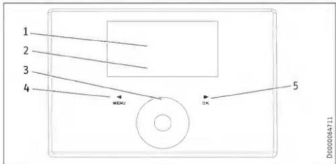
1 Text field
2 Appliance status symbols
3 Touch-Wheel
4 "MENU" button
5 "OK" button
4.1.1 Display
If you do not perform any settings for a while, the display illumination switches off and the home screen appears.
Press any button to switch the illumination back on again.
4.1.2 Symbols
| Symbol | Description |
| Time program mode: The set fan program is active. Depending on the setting, the unit is operated at various fan stages. The number indicates the fan setting. | |
| Intens. vent.: The unit runs at the highest fan setting for the set period of time. | |
| Condensate prevention (depending on unit): Condensate prevention is active. | |
| Filter change: Change the filters when this symbol appears. | |
| Fault: The symbol is displayed continuously if there is a fault. | |
| Bypass mode: When the conditions are met for bypass mode, the "bypass mode" symbol appears. When the symbol appears and you wish to activate bypass mode, open the window on which the contact switch is installed. When the "bypass mode" symbol goes out, close the window. | |
| Frost prot.: The preheating coil for frost protection is switched on. | |
| Fan disable: The symbol is displayed in the event of the "Enable fan" is set to "Off". |
4.1.3 Controls
| Operating controls | Description |
| "MENU" button | Press this button for approx. one second to call up the menu from the home screen. |
| Within the menu, press this button to go back one menu level at a time. | |
| When setting a parameter value, press this button to exit setting of the parameter. Any changes made will not be saved in this case. | |
| "OK" button | Pressing the "OK" button within the menus confirms the selected parameter and takes you to the next menu level down. |
| In order to set the parameter, you must first make it editable by pressing the "OK" button. Then you can change the value with the Touch-Wheel. | |
| Once you have set the parameter, confirm your entry with the "OK" button. | |
| Touch-Wheel | From the home screen, you can select the following parameters by turning the Touch-Wheel: "Humidity prot.", fan settings "Stage 1" or "Stage 2", "Time program mode", "Intens. vent.", "Favourites", "Direct selec." and "Function block". Confirm the selection with the "OK" button. |
| Use the Touch-Wheel to select a parameter or value in the menu. | |
| If you turn the Touch-Wheel quickly, the increment size changes after a while. |

Notice
Gloves, wet hands or moisture on the touch-sensitive operating controls make it more difficult to make entries.
4.1.4 Operation
▶ Press the "MENU" button to access the menus from the home screen.
▶ Turn the Touch-Wheel to move to the next parameter.
▶ Press "OK" to change the value of the parameter displayed.
▶ Adjust the value with the Touch-Wheel.
▶ Press "OK" to save the selected value. If you do not confirm the change with the "OK" button, the change will not be saved.
If you do not make any changes for a while, the display automatically switches from the menu structure back to the home screen. Recent parameter changes not yet been confirmed with "OK" will be lost.
If the Touch-Wheel and buttons are not used for a while, the programming unit is locked.
▶ Touch "MENU" for three seconds to activate the programming unit.
4.2 Parameters adjustable from the home screen
4.2.1 Activating humidity protection
In the home screen, turn the Touch-Wheel until "Humidity prot." appears. Press "OK".
Humidity protection control is active. The moisture in the extract air is measured and if humidity is high, the unit starts to ventilate. Humidity protection starts 24 hours after you have activated the "Humidity prot." operating mode.
4.2.2 Selecting the fan setting
▶ Using the Touch-Wheel, select the fan setting "Stage 1" or "Stage 2". Press "OK".
The selected fan setting is active.
4.2.3 Activating time program mode
The "Time program mode" symbol indicates that the fan program is activated.
▶ If the fan program is not activated, select "Time program mode". Press "OK".
The displays shows the "Time program mode" symbol.
For times where there is no fan program defined, the unit operates at fan stage 2.

Notice
If you switch the unit to Time program modea fan program must be entered in the "Programs" menu. Otherwise the unit continues to run without a time limit in fan stage 2.
4.2.4 Switching on Intens. vent.
▶ Switch on Intens. vent. with the Touch-Wheel and the "OK" button or with an external pushbutton.
When intensive ventilation is switched on, the "Intens. vent." symbol is shown.
After expiry of the period of time set under "Intens. vent. time", the unit switches back to the previously selected fan setting.
When intensive ventilation switches off, the "Intens. vent." symbol goes out.
4.2.5 Setting favourites
▶ Select "Favourites" using the Touch-Wheel. Press "OK".
This will take you from the standard view directly to the favourites in the "Settings" menu.
▶ Select the required favourites. Press "OK".
The set favourites F1, F2 and F3 are displayed on the home screen.
4.2.6 Activating function block
▶ Select "Function block" using the Touch-Wheel. Press "OK".
A 60 second countdown and "Maintenance" are displayed.
Then you can wipe the programming unit clean without inadvertently changing any settings. The function block terminates after 60 seconds.
4.2.7 Direct selec.
Use direct selection to move from the standard view directly to the adjustable or readable parameters.
▶ Select "Direct selec." using the Touch-Wheel. Press "OK".

Notice
The table shows only the direct selection parameters to be set by the appliance user. The other direct selection parameters shown on the display may only be set by a qualified contractor or the service department.
Direct selection parameters
| Description | Code level | Unit | Min. | Max. | Options | Standard | |
| P1 | Set room temperature | A0 | °C | 5 | 28 | 20 | |
| P2 | Intens. vent. time | A0 | min. | 1 | 24 | 30 | |
| P3 | Operating mode heat recovery bypass | A0 | Disabled (0) | Bypass/window contact (1) | Outdoor air routing automatic (2) | Extract air routing autom. (3) | ||||
| P4 | Filter reset | A0 | Off | On | Off | |||
| P28 | Enable fan | A0 | Off | On | Off | |||
| P35 | Cooling/heating, heat recovery bypass | A0 | Cooling/heating (1) | Cooling (2) | Heating (3) | (1) | |||
| P80 | Day | A0 | |||||
| P81 | Time | A0 | 00:00 | 23:59 |
4.3 Menus

Notice
Some parameters are protected by a code and can only be set by a qualified contractor or the service department. Depending on the set code, not all parameters may be displayed in the individual menus.
▶ Press the "MENU" button to access the menus from the home screen.
| Menu | Description |
| ■ Info | Information about the actual values of the appliance |
| ■ Diagnostics | Fault messages, operating time, maintenance intervals |
| ■ Programs | Fan program |
| ■ Settings | Adjustable values and functions |
4.3.1 "Info" menu
| ■ Info | Value |
| □ ■ Bypass status | Off | On |
| □ ■ Extract air temp. | °C |
| □ ■ Extract air hum. | % |
4.3.2 "Diagnostics" menu
| ■ Diagnostics | Value |
| □ ■ Notification list | 0-10 |
| □ ■ Filter runtime | h |
| □ ■ Filter reset | Off | On |
■ Diagnostics
□ ■ Notification list
The faults most recently registered by the appliance are stored in the notification list. The most recent fault is stored in #1, the oldest error in #10.
If no faults are entered, dashes are shown. Possible faults are listed for qualified contractors in the "Troubleshooting" chapter.
Filter runtime
The filter runtime is dependent on the operating conditions and has been defined by the qualified contractor.
□■ Filter reset
▶ After changing the filters, set the "Filter reset" to "On".
The unit resets the filter runtime to 0 and the "Filter reset" is automatically reassigned the value "Off". The filter change warning signal goes out.
4.3.3 "Programs" menu
| Programs | Value |
| Fan program | Monday |
| Tuesday | |
| Wednesday | |
| Thursday | |
| Friday | |
| Saturday | |
| Sunday | |
| Monday - Friday | |
| Saturday - Sunday | |
| Monday - Sunday |
Programs
□■Fan program

Notice
For times where there is no fan program defined, the unit operates at fan stage 2.
You cannot switch on fan stage 3 with fan programs.
For the fan programs, you can specify a fan setting, time, day of week or time block.
Setting switching time pairs
You can set three switching time pairs for each day of the week or time block. The switching time pairs are shown on the display, to the right of the clock.
Each switching time pair consists of a start time and an end time. After a switching time pair has expired, the unit switches to "Stage 2" operating mode.
Periods around midnight
Switching time pairs can be programmed only up to 24:00. If you want to choose periods that extend beyond midnight, you will need to set an additional switching time pair for the following day.
In the "Programs" menu, select "Fan program" using the Touch-Wheel. Press "OK".
▶ Select a day of the week or a time block. Press "OK".
▶ Select one of the three switching time pairs. Press "OK".
▶ Select "Stage". Press "OK".
▶ Select the fan setting. Press "OK".
▶ Select "Start". Press "OK".
▶ Set the start time. Press "OK".
▶ Select "End". Press "OK".
▶ Set the end time. Press "OK".
The fan program is now set.
▶ In standard view, select "Time program mode". Press "OK" to activate the fan program.

Notice
If there are fan programs with identical times, the higher level switching time pairs and individual days of the week have priority.
Example
| Switching time pairs | Stage | |
| Monday to Friday | 06:00 - 22:00 | 2 |
| 22:00 - 06:00 | 1 | |
| Saturday, Sunday | 07:00 - 23:00 | 2 |
| 23:00 - 07:00 | 1 |
| Fan programDay of the week or time block | Stage | Start | End |
| Monday - Friday | 1 | 22:00 | 24:00 |
| Monday - Friday | 1 | 00:00 | 06:00 |
| Saturday - Sunday | 1 | 23:00 | 24:00 |
| Saturday - Sunday | 1 | 00:00 | 07:00 |
For times where there is no fan program defined, the unit operates at fan stage 2.
Deleting switching time pairs
▶ To delete a switching time pair, select the "Start" or "End" of a switching time pair.
▶ Turn the Touch-Wheel to the left beyond 00:00 until dashes “-- --” are displayed. Press "OK".
Resetting one of the times to "--::--" automatically resets the other time of the switching time pair.
Deleting day of the week or time block
▶ Delete all three switching time pairs to delete the fan program for the weekday or time block.
4.3.4 "Settings" menu
| Settings | Value |
| □■ View | Code for qualified contractor |
| □■ General | |
| □□■ Time/date | Day |
| Hour:Minute | |
| □□■ Language | Deutsch |
| English | |
| Francais | |
| Nederlands | |
| Italiano | |
| Polski | |
| Cesky | |
| Magyar | |
| Slovensko | |
| 中文 | |
| Slovensky | |
| 日本語 | |
| □□■ Contrast | 1 - 10 |
| □□■ Brightness | % |
| □□■ Touch sensitivity | 1 - 10 |
| □□■ Touch boost | 1 - 10 |
| □□■ Prog. unit software | |
| □■ Air flow rate | Only for qualified contractors |
| □■ Favourites | |
| □□■ F1 | Bypass status |
| F2 | Extract air temp. |
| F3 | Extract air hum. |
| Filter runtime | |
| Device software version | |
| Device software patch | |
| Mobile device serial no. | |
| □■ Humidity prot. | Only for qualified contractors |
| □■ Intensive ventilation | |
| □□■ Intens. vent. time | min |
| □■ Heat recovery bypass | |
| □□■ Set room temperature | °C |
| □□■ Operating mode heat recovery bypass | Disabled |
| Bypass/window contact | |
| Outdoor air routing automatic | |
| Extract air routing autom. | |
| □□■ Cooling/heating. heat recovery bypass | Cooling/heating |
| Cooling | |
| Heating | |
| □■ Frost protection | Only for qualified contractors |
| □■ Condensate prevention | Only for qualified contractors |
| □■ Enable fan | Off |
| On | |
| □■ Ventilation unit | |
| □□■ Device software version | |
| □□■ Device software patch | |
| □□■ Mobile device serial no. |
Settings
□ View
Only those parameters which are enabled for the appliance user, and therefore accessible without a code, are shown in the default settings.
Qualified contracts can use the "View" parameter to enable actual values and parameters, which are reserved for qualified contractors.
□ General
□□■ Time/date
The "Time/date" parameter enables you to set the day of the week and the current time.
□□■Language
The "Language" parameter enables you to select the language of the display.
□ □ ■ Contrast
The "Contrast" menu item allows you to adjust the contrast of the display.
□□■Brightness
The "Brightness" menu item allows you to set the brightness of the display.
□□■ Touch sensitivity
The "Touch sensitivity" parameter enables you to adjust the touch sensitivity of the Touch-Wheel and the sensor keys.
□□■ Touch boost
The "Touch boost" lets you adjust the reaction speed of the Touch-Wheel and the sensor keys.
□ □ ■ Favourites
In the "Favourites" parameter, you can select up to three parameters that you wish to have displayed in the standard display.
Intensive ventilation
Intens. vent. time
This parameter defines the runtime for intensive ventilation. After this time has expired, the unit switches back to the previously selected fan setting. If the intensive ventilation is switched on with an external pushbutton, this parameter defines how long the intensive ventilation continues to run after the button has been pushed.
□ Heat recovery bypass
□□■ Set room temperature
Use this parameter to set the outside temperature from which the outdoor air bypasses the heat exchanger and flows into the building through open windows.
▶ Use the Touch-Wheel to set the required Set room temperature. Press "OK".
□□■ Operating mode heat recovery bypass
| Effect | |
| Disabled | Bypass mode is permanently disabled. Air flows through the heat exchanger. |
| Bypass/window contact | Bypass mode is enabled. The "Bypass mode" symbol appears on the display. When the window with the window contact is open, the air stream bypasses the heat exchanger. |
| Outdoor air routing automatic | Bypass mode operates with summer day detection. This option is set in the delivered condition. The "Bypass mode" symbol appears on the display. |
| Extract air routing autom. | Bypass mode operates subject to the extract air temperature. The "Bypass mode" symbol appears on the display. |
The appliance checks whether a window contact is connected and activated at X18. When bypass mode is enabled and the window with the window contact is open, only the extract air fan is activated and the supply air fan switches off. The air flow bypasses the heat exchanger.

Notice
The qualified contractor can set the parameters mentioned in the description of this parameter.
- Temperature to enable heat recovery bypass
- Temperature to block heat recovery bypass
- Hysteresis for heat recovery bypass
- Temp. differential for heat recovery bypass
□□□■ Outdoor air routing automatic: Bypass mode with summer day detection
For bypass mode to be enabled, the following condition must be met for 60 minutes:
- Set room temperature + Temp. differential for heat recovery bypass < Outdoor air temp.
If all the following conditions are met, the appliance switches to bypass mode.
- Extract air temp. - Hysteresis for heat recovery bypass > Outdoor air temp.
- Extract air temp. > Set room temperature
If one of the following conditions is met, the appliance terminates bypass mode.
- Outdoor air temp. < Temperature to block heat recovery bypass
- Extract air temp. - Hysteresis for heat recovery bypass < Outdoor air temp.
- Extract air temp. < Set room temperature
□□□■ Extract air routing autom.: Bypass mode subject to extract air temperature
For bypass mode to be enabled, the following condition must be met for 60 minutes:
- Set room temperature + Temp. differential for heat recovery bypass < Extract air temp.
This delayed enabling prevents cooling down in spring and autumn.
If all the following conditions are met, the appliance switches to bypass mode.
- Extract air temp. - Hysteresis for heat recovery bypass > Outdoor air temp.
- Extract air temp. > Set room temperature
If one of the following conditions is met, the appliance terminates bypass mode.
- Outdoor air temp. < Temperature to block heat recovery bypass
- Extract air temp. - Hysteresis for heat recovery bypass < Outdoor air temp.
- Extract air temp. < Set room temperature
□□■ Cooling/heating, heat recovery bypass
▶ Set the bypass mode control according to the temperature.
| Parameter | Effect |
| Cooling/heating | Depending on the temperature, use the outdoor air for cooling or heating. |
| Cooling | Summertime: Use cool outdoor air. |
| Heating | Spring and autumn: Use warm outdoor air. |
Enable fan
You can switch off the fans at any time via the programming unit menu, e.g. to deactivate ventilation if there is a fire.
| Effect | |
| Off | The fans are disabled. The "Fan disable" symbol appears on the display. |
| On | The fans are enabled. |
4.4 Switching off the appliance

Property damage
If you interrupt the power supply to the appliance, check that humidity protection is ensured for the building.
The appliance has no ON/OFF switch. Disconnect the power supply at the fuse/MCB in the domestic distribution board.
5. Maintenance, cleaning and care
Maintenance by the user is limited to filter inspection and replacement required at certain intervals.
5.1 Replacement filters
LWZ 130, LWZ 130 Enthalpie
| Product name | Description | Classification in accordance with ISO 16890 | Quantity |
| FMS G4-10 130/135 | Coarse particle filter mat | ISO Coarse > 60 % (G4) | 10 |
| FMK M5-2 130/135 | Fine filter | ePM10 ≥ 50 % (M5) | 2 |
| FMK F7-2 130/135 | Fine filter | ePM _1 ≥ 50 % (F7) | 2 |
LWZ 130 E-W
| Product name | Descrip-tion | suitable for | Classification in accordance with ISO 16890 | Quantity |
| FMS G4-10 130/135 | Coarse particle filter mat | Installation below the ceiling | ISO Coarse > 60 % (G4) | 10 |
| FMS G2-2 130/135 | Coarse particle filter mat | Wall mounted installation | ISO Coarse > 30 % (G2) | 2 |
| FMK F7-2 130/135 | Fine filter | Installation below the ceiling or on the wall | ePM1 ≥ 50 % (F7) | 2 |
5.2 Filter inspection and replacement

Property damage
Never operate the unit without filters.
▶ Inspect the filters for the first time three months after commissioning the appliance.
When the total fan runtimes reach the "Filter change interval" parameter set by the qualified contractor, the programming unit displays the filter change warning signal.
The qualified contractor can lengthen or shorten the interval for inspecting filters depending on the level of contamination.
Change the filters when the filter change warning signal appears. Change the filters if the surface is covered completely in dirt or the filter is discoloured throughout.
Change the filters at least every 12 months.
Filter inspection
▶ Disconnect the appliance from the power supply.
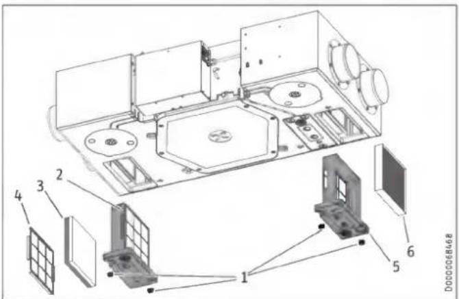
1 Wing screw
2 Filter cassette, extract air filter
3 Filter mat
4 Grille
5 Filter cassette, outdoor air filter
6 Outdoor air filter
▶ Undo the wing screw on the filter cassette of the extract air filter by turning the screw anti-clockwise.
▶ Remove the filter cassette from the appliance.
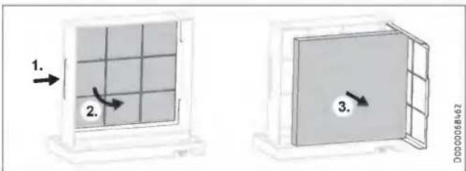
If necessary, place a new filter in the filter cassette. To do this, slide the grille - behind which the filter mat is located - a little to one side and swing the grille forwards like a door.

Property damage
Operate the appliance with at least the recommended filter class. Ensure that filters are fitted accurately so they can function properly.
▶ Ensure that the direction of air flow through the filter is correct.
M5, F7: The direction of flow is indicated by an arrow on the side of the filter.
Coarse particle filter mat (black G2, white G4): This filter does not have a preferred direction of flow.
▶ After inserting the filter, flip the grille shut again.
▶ Push the filter cassette into the appliance. Ensure that the filter cassette is installed in the intended position. The arrow on the filter cassette and the arrow on the appliance must point in the same direction.
▶ To secure the filter cassette, turn the wing screw clockwise.
▶ Undo the wing screw on the filter cassette of the outdoor air filter by turning the screw anti-clockwise.
▶ Remove the filter cassette from the appliance.
▶ If necessary, place a new filter in the filter cassette.
▶ Push the filter cassette into the appliance. Ensure that the filter cassette is installed in the intended position. The arrow on the filter cassette and the arrow on the appliance must point in the same direction.
▶ To secure the filter cassette, turn the wing screw clockwise.
▶ Switch on the power supply to the appliance.
▶ After changing the filters, set the "Filter reset" to "On".
The unit resets the filter runtime to 0 and the "Filter reset" is automatically reassigned the value "Off". The filter change warning signal goes out.
▶ Make a note of the filter change date.

Notice
- Log the filter inspection in the appendix of this manual.
▶ Order new filters in good time or purchase a filter subscription.

Notice
If other filters are installed in the system, e.g. filters in the extract air vents or a filter box, also perform the inspection there and change the filter(s) if necessary.
6. Troubleshooting
The faults detected by the appliance are stored in the notification list.
If you cannot remedy the fault, contact your qualified contractor. To facilitate and speed up your enquiry, please provide the serial number from the type plate (000000-0000-000000). The type plate is located on the control panel on the side of the appliance.
INSTALLATION
7. Safety
Only a qualified contractor may carry out installation, commissioning, maintenance and repair of the appliance.
7.1 General safety instructions
We guarantee trouble-free function and operational reliability only if original accessories and spare parts intended for the appliance are used.
7.2 Instructions, standards and regulations

WARNING Injury
Observe all country-specific fire prevention regulations and requirements concerning the installation of ventilation systems. In Germany, these are particularly the building regulation guideline on fire prevention requirements of ventilation systems in its applicable version.

Notice
Observe all applicable national and regional regulations and instructions.
7.3 Operation of the appliance in buildings with combustion equipment
The term "combustion equipment" used below includes, for example, tiled stoves, fireplaces and equipment with gas combustion.

WARNING Injury
Ventilation units can generate negative pressure in the dwelling. If combustion equipment is operating at the same time, combustion exhaust gases can penetrate the combustion equipment installation room. It is therefore important to observe a number of points for simultaneous operation of a ventilation unit and combustion equipment.
The planning, installation and operation of the ventilation unit and combustion equipment must be carried out in accordance with national and regional regulations.
7.3.1 Planning safety measures
Together with the relevant authorities, engineers plan the safety measures that are required for simultaneous operation of a ventilation unit and combustion equipment.
Alternate operation
Alternate operation means that, when the combustion equipment is commissioned, the mechanical ventilation system is switched off and/or cannot be started. Alternate operation must be ensured by appropriate measures, e.g. automatically enforced shutdown of the ventilation unit.
Simultaneous operation
For simultaneous operation of combustion equipment and a mechanical ventilation system, we recommend choosing approved room sealed combustion equipment (in Germany, with DIBt approval).
If open-flue combustion equipment is operated in the dwelling at the same time as a ventilation unit, combustion exhaust gases must be prevented from penetrating the home due to negative pressure in the room.
The ventilation unit may only be operated in combination with intrinsically safe combustion equipment. This combustion equipment has, for example, a draught hood or an exhaust gas monitor and is approved for operation in conjunction with ventilation units. Alternatively, external, tested safety equipment can be connected to monitor the operation of the combustion equipment. For example, you can install differential pressure monitoring to monitor the chimney draught and to switch off the ventilation unit in the event of a fault.
The equipment for differential pressure monitoring must fulfil the following requirements:
- Monitoring of the differential pressure between the connection piece to the chimney and the room where the combustion equipment is installed
- Possibility of matching the shutdown value for the differential pressure to the minimum draught requirement for the combustion equipment
- Floating contact to switch off ventilation
- Optional connection of a temperature capturing device so that differential pressure monitoring is only enabled when the combustion equipment is in operation and so that unwanted shutdowns due to environmental influences can be avoided

Notice
Differential pressure switches that use the pressure differential between the outdoor air pressure and the pressure in the combustion equipment installation room as a response criterion are not suitable.

Notice
We recommend installing and regularly maintaining a carbon monoxide detector in accordance with EN 50291 for operation of any combustion equipment.
7.3.2 Commissioning
When commissioning the ventilation unit, it is important to check and document in the commissioning log that combustion exhaust gases are not penetrating the dwelling in a quantity that is harmful to health.
Commissioning in Germany
Acceptance is carried out by the local flue gas inspector.
Commissioning outside Germany
Acceptance must be carried out by a specialist. In case of doubt, you must involve an independent expert in the acceptance procedure.
7.3.3 Maintenance
Regular maintenance of the combustion equipment is prescribed. Maintenance includes checking the exhaust gas extraction system, the free pipe cross-sections and the safety equipment. The qualified contractor responsible must verify that there is a sufficient flow of combustion air.
8. Appliance description
| LWZ 130 | LWZ 130 Enthalpie | LWZ 130 E-W | |
| Installation below the ceiling | x | x | x |
| Wall mounted installation | - | - | x |
8.1 Standard delivery
The following are delivered with the appliance:
- Hardwired, wall mounted programming unit with wall mounted enclosure, adaptor cable
- Anti-vibration mount
- Plug and strain relief enclosure for the programming unit and the external floating contacts or switches (Intens. vent., window contact)
LWZ 130 E-W
- Class G4 filter: If the appliance is installed horizontally, this filter must be installed as an extract air filter.
8.2 Accessories
You can obtain ventilation pipes, extract air and supply air vents and similar accessories from us.
LWZ 130
| Product name | Part number | ||
| Condensate pump with mounting enclosure | PK 130 | 238140 |
LWZ 130 E-W
| Product name | Part number | ||
| Pipe bend with condensate drain, condensate drain hose, hose clip, mounting bend | Cond C 125 | 206040 | This condensate connection must be installed if the appliance is mounted vertically on the wall. |
9. Preparation
9.1 Storage

Property damage
Never store the appliance in dusty places.
9.2 Installation site

WARNING Electrocution
You must not install the appliance in safety zones 0, 1 and 2. The safety zones are defined in the IEC 60364-7-701 standard.

Property damage
Never install the appliance outdoors.

Property damage
▶ Check whether the ceiling or wall can bear the weight of the appliance.

Property damage
In dwellings in which only one air conditioning unit is installed or planned, the appliance must only be operated with one enthalpy heat exchanger. Otherwise property damage may arise due to the formation of condensation.
- The installation room must be free from the risk of frost.
- Never install the unit at an angle.
- LWZ 130 E-W: If you are installing the appliance vertically on the wall: The installation room must have an adequate condensate drain with siphon.
The type and location of the outside air intake must ensure that the least polluted outdoor air in the area of the building and surroundings is drawn in.
The outside air intake for controlled mechanical ventilation must be at least the following height above ground level: 700 mm. In addition, you must observe the minimum suction height from the standard applicable to you.
Avoid outdoor air intake in locations with polluted air:
- car parks and roads
- under bushes and trees
- in the proximity of waste containers
- locations contaminated with microorganisms, dust or ash
LWZ 130 E-W: Permissible installation position for wall mounting
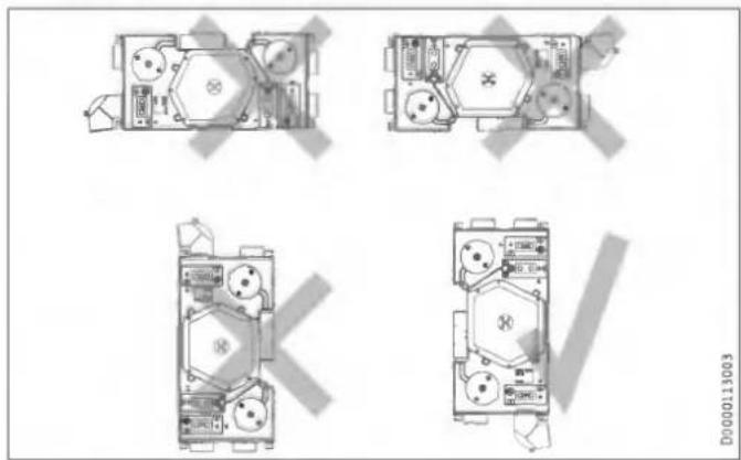
natural_image
Top-down architectural floor plan of a multi-room building with visible furniture and equipment (no text or labels)9.2.1 Minimum clearances
Installation below the ceiling


Ensure that the appliance is accessible for filter replacement and maintenance. Mount a cover (600 x 1200 mm) beneath the appliance or design the suspended ceiling in such a way that it is removable under the appliance.
Wall mounted installation
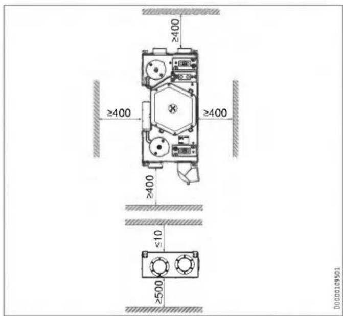
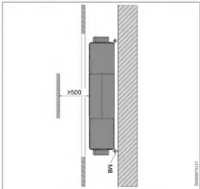
Ensure that the appliance is accessible for filter replacement and maintenance. Fit a flap (600 x 1370 mm) in front of the appliance.
9.3 Transport

Property damage
If possible, transport the appliance to the installation location in its original packaging.
If the appliance is transported without packaging and without using a pallet, e.g. to carry it up or down stairs, its outer casing may be damaged.
To transport the appliance without packaging, first remove the front panel of the appliance. See chapter "Installation / Removing the front panel".

Property damage
Never use the air connections as handles for carrying the appliance.
10. Installation

WARNING Electrocution
Do not install the appliance if it is damaged and there is a risk that live components could be touched.
▶ Check the appliance for external damage.

Property damage
▶ Make sure that there are no sharp objects at the installation location that could drill through the outer envelope of the appliance.
10.1 Mounting the appliance
| LWZ 130 | LWZ 130 Enthalpie | LWZ 130 E-W | |
| Installation below the ceiling | x | x | x |
| Wall mounted installation | - | - | x |

Property damage
▶ Check whether the ceiling or wall can bear the weight of the appliance.

Property damage
▶ Never install the unit at an angle.

Notice
The filter cassettes are located at the bottom of the appliance.

Notice
Install the appliance before mounting the ceiling panels of the suspended ceiling.

Notice
▶ When positioning the appliance, ensure there is sufficient space to install the supply and extract air ducts (see chapter "Preparations / Installation site / Minimum clearances").
▶ Drill holes in the ceiling or wall for mounting the appliance with threaded pins or hanger bolts.
▶ Fit the following parts onto each threaded pin in the sequence described.
Installation below the ceiling

1 Nut
2 Washer
3 Anti-vibration mount
4 Appliance mounting
5 Anti-vibration mount
6 Washer
7 Nut
8 Nut (Lock nut)
Wall mounted installation
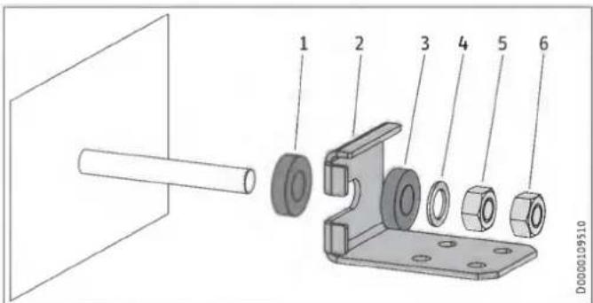
1 Anti-vibration mount
2 Appliance mounting
3 Anti-vibration mount
4 Washer
5 Nut
6 Nut (Lock nut)
Aligning the appliance
▶ Use a spirit level to check that the appliance is straight.
▶ Level the appliance horizontally by turning the nuts.
10.2 Connecting the condensate drain hose

Notice
If installing appliances with enthalpy heat exchangers below the ceiling, you do not need to connect a condensate drain hose to the long side of the appliance.

Property damage
The weight of the condensate drain hose and condensate pump must not exert a leverage effect on the appliance condensate drain connection. This could cause the condensate drain connection to leak or break off.
▶ Secure the condensate drain hose, e.g. to the ceiling.

Property damage
To ensure that condensate drains correctly, always lay the condensate drain hose without any kinks. Lay the condensate drain hose with a fall of at least 10 %. The appliance must be installed horizontally.
The drain pipe may only contain one siphon. The condensate must be able to drain freely downstream of the siphon.
The condensate must drain away via the domestic sewer system. The pipes must not rise in the domestic sewer system downstream of the siphon. The condensate drain must be free from the risk of frost.

Notice
Prevent air from being drawn in through the condensate drain.
▶ Install the condensate drain hose in such a way as to create a siphon with a water trap height of at least 80 mm.
▶ Before connecting the condensate drain hose to the appliance, pour water into the siphon.
▶ Push a condensate drain hose onto the condensate drain connection.
▶ Prevent the condensate drain hose from slipping off the condensate drain connection, e.g. with a cable tie.
10.2.1 Optional for LWZ 130: Condensate pump
Standard delivery
- Pump assembly: The pump assembly consists of a pump module and a float module that are already connected electrically and to a condensate hose in their delivered condition.
- Vent hose
- Hose bend for the connection between appliance and float module.
- 3 cable ties
Installation
▶ Flush the condensate pan with water so that no impurities (e.g. metal swarf or EPS beads) block the condensate pump.
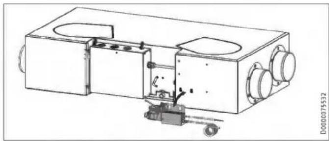
natural_image
Technical line drawing of a mechanical device with internal components and mounting holes (no text or symbols)▶ Hook the condensate pump assembly onto the hooks provided on the long side of the appliance.
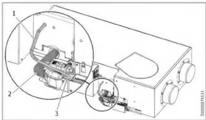
1 Vent hose
2 Hose bend
3 Vent hose
▶ Push the supplied hose bend onto the appliance condensate drain connection. Secure the hose bend with a cable tie.
▶ Push the other end of the hose bend onto the connection on the float module. Secure the hose bend with a cable tie.
▶ Connect the supplied vent hose to the float module. The connection on the float module is above the condensate outlet.
▶ Undo the cable tie that has sealed the vent hose which comes out of the appliance.
▶ Push the vent hoses into one another.
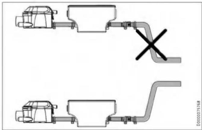
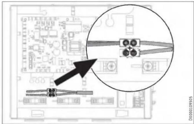
natural_image
Technical line drawing of two mechanical components with a cross symbol indicating a dislocation or failure (no text or labels present)▶ Connect a condensate hose to the condensate outlet of the condensate pump and route it into a drain. In order for the condensate pump not to run dry, the condensate hose behind the pump must not route directly downwards.
▶ Connect the power supply of the condensate pump.
| Colour | |
| GN | Ground |
| WH | Neutral |
| BK | Phase |
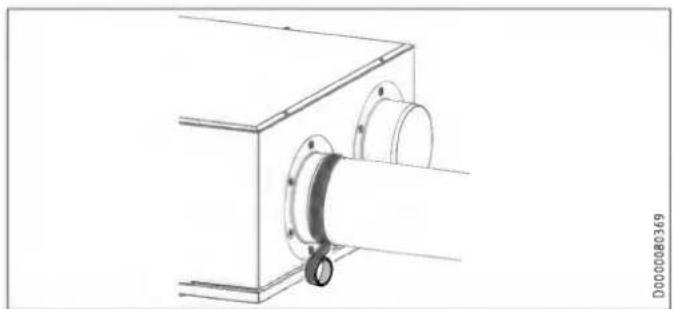
10.3 LWZ 130 E-W: Pipe bend with condensate drain
If the appliance is mounted vertically on the wall, the "extract air" connection must be replaced with a pipe bend with condensate drain.
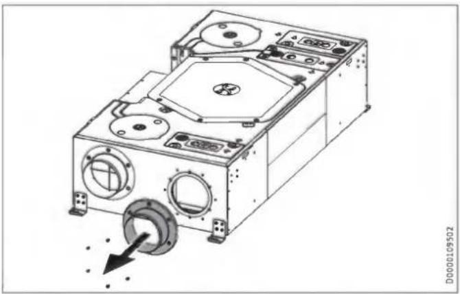
natural_image
Technical line drawing of a mechanical device with circular components and a dial indicator (no text or symbols)▶ To remove the "extract air" connection, undo the screws.
▶ Remove the "extract air" connection and its gasket.
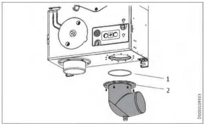
1 0-ring
2 Pipe bend with condensate drain
▶ Check that the preassembled O-ring is seated correctly to ensure that it seals the pipe bend to the appliance.
▶ Attach the pipe bend to the extract air opening on the appliance with screws.
Connecting the condensate drain hose
Property damage
The drain pipe may only contain one siphon. The condensate must be able to drain freely downstream of the siphon. The condensate must drain away via the domestic sewer system. The pipes must not rise in the domestic sewer system downstream of the siphon. The condensate drain must be free from the risk of frost.

Notice
To ensure the unit is airtight, there may be no interruption in the condensate drain between the unit and the trap. Use the supplied condensate drain hose and mounting bend.
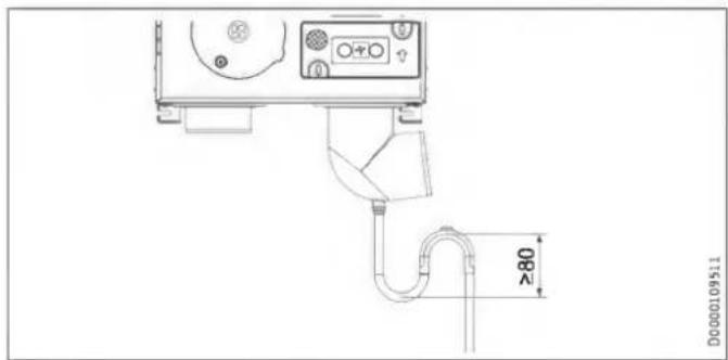
▶ Before connecting the condensate drain hose to the appliance, pour water into the trap.
▶ Use the mounting bend included in the standard delivery to install the condensate drain hose in such a way as to create a siphon with a water trap height of at least 80 mm.
natural_image
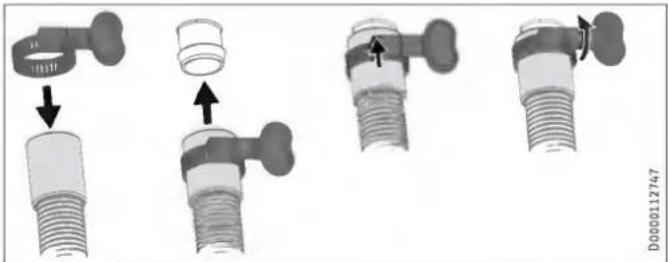
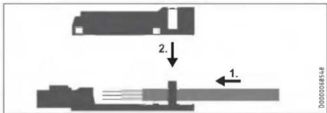
Mechanical assembly diagram showing four stages of a valve fitting with arrows indicating movement (no text or symbols present)- Secure the condensate drain hose to the condensate drain of the pipe bend using the hose clip provided.
10.4 Air ducts
Property damage
Never link cooker hoods to the ventilation system.
Property damage
During installation, ensure that no metal swarf enters the pipework. However, should this occur, remove this debris, otherwise the fans may be damaged.
Install the air ducts using materials that can be obtained from us or with commercially available folded spiral-seam tubes.
10.4.1 Insulation against condensation
Property damage
When warm air meets cold surfaces, condensation can result.
▶ For outdoor air and exhaust air ducts, use vapour proof thermally insulated pipes.
▶ If the supply and extract air ducts are routed through unheated rooms, insulate these ducts as well.
10.4.2 Connecting air ducts to the appliance
You can connect air ducts with two different diameters to the appliance.
Air ducts with diameter DN 125
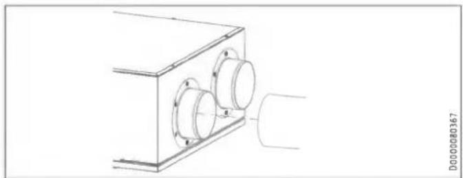
natural_image
Technical line drawing of a mechanical assembly with two circular components mounted on a rectangular base (no text or symbols)▶ Push the air duct onto the air connection.
natural_image
Technical line drawing of a mechanical assembly with a cylindrical component inserted into a housing (no text or symbols)- Secure the air duct at the appliance air duct connection with self-adhesive aluminium sealing tape.
Optional: Air ducts with diameter DN 150
▶ Remove the air duct connectors mounted in the delivered condition by undoing the screws.
▶ Screw the new air duct connectors onto the appliance.
10.4.3 External wall outlets
Install the outdoor air intake into the building at a location where contamination (dust, soot, odours, flue gas, microorganisms, ash, exhaust air) is as low as possible.
When installing external wall outlets, prevent any short circuit between the air intake and the air discharge.
10.4.4 Silencers
▶ Install a silencer in both the supply air duct and the extract air duct. Install these silencers as close as possible to the appliance, so that noise is suppressed at an early stage.
We recommend installing additional silencers if required to avoid sound transmission.
If a room with a high noise level needs to be ventilated, install additional silencers upstream of this room to reduce sound transmission to the neighbouring rooms.
Aspects such as carried voices and impact sound must also be taken into consideration in the case of ducts embedded in concrete. Carried voices should be avoided by designing the duct with separate branches to the vents. If necessary, insulate the supply air ducts, e.g. if they are mounted outside the insulated wall panel.
10.4.5 Overflow apertures
Living rooms and bedrooms are only supplied with air. Air is only extracted from rooms where odours and moisture are generated. Ensure an unimpeded overflow and consequently air balancing. Install ventilation grilles in internal doors or walls, or enlarge the air gap beneath the door to ≥ 8 mm.
10.4.6 Cleaning apertures
▶ Fit cleaning apertures when installing the air ducts, so that the air ducts can be inspected and cleaned at regular intervals.
10.4.7 Supply and extract air vents
Supply and extract air vents for the living space are available for wall or ceiling mounting.
When venting the kitchen, ensure that the extract air vent is fitted as far as possible from the cooker.
10.5 Programming unit
10.5.1 Installation location of the programming unit
The programming unit is connected with an I²C bus. The length of the bus cable between the programming unit and ventilation unit must not exceed 20 m.
Observe the following installation location requirements to ensure correct function.
▶ Fit the programming unit to an internal wall, but not in a recess.
▶ Do not cover the programming unit with curtains or similar.
▶ Do not expose the programming unit to any direct external heat source (e.g. the sun, a heater or a TV set).
▶ Avoid direct draughts coming from windows and doors.
10.5.2 Installing the programming unit
▶ Route a 4-core bus cable from the ventilation unit to the mounting position of the programming unit. Use a screened electronic cable such as LiYCY 2x2x0.8 mm². Do not route the cable parallel to a three-phase cable.
The BUS cable must protrude 20 to 30 cm out of the wall to allow installation.
Remove programming unit from the wall mounted enclosure
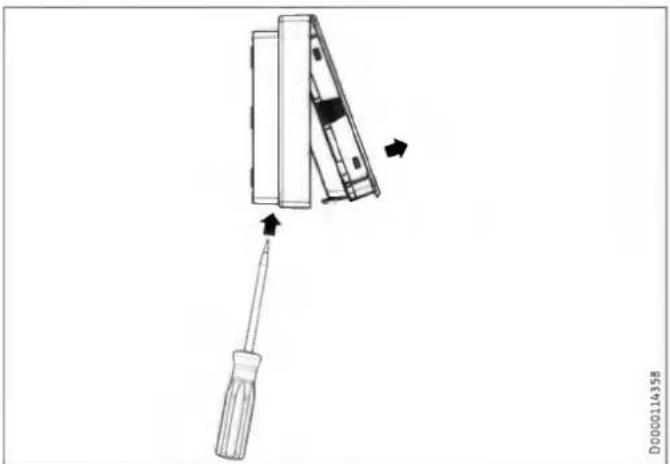
natural_image
Diagram of a screwdriver holding a device, with arrows indicating movement (no text or symbols)▶ Release the locking tab found in the opening on the underside of the wall mounted enclosure. Press the locking tab with a screwdriver.
Installation with a flush box
For securing to a wall we recommend using a flush box, which can hold the part of the bus cable protruding from the wall.
▶ Make sure that the screws supporting the flush box are arranged either vertically or horizontally opposite one another.
▶ Route the bus cable through the aperture in the wall mounted enclosure from the back.
Installation without a flush box
▶ To secure the wall mounted enclosure, drill four holes ( 5 mm).
▶ When routing the BUS cable, be careful not to damage the cable when drilling the fixing holes.
In the area around the cable entry (behind the wall mounted enclosure), a reservoir needs to be made to hold 20 to 30 cm of data cable.
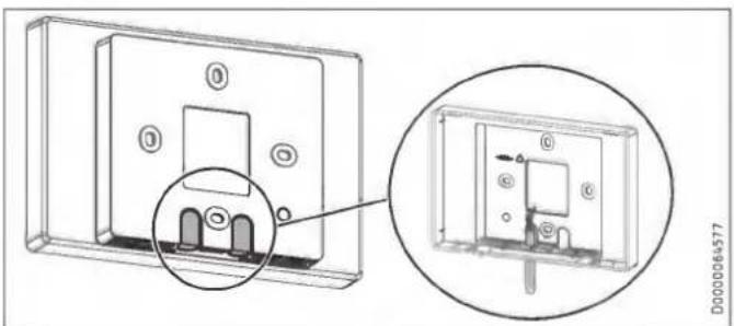
natural_image
Technical diagram of a device housing with an inset close-up showing internal components (no text or symbols)▶ Break out one of the knock-outs in the wall mounted enclosure.
▶ Route the bus cable through the aperture from the back.
Installing the wall mounted enclosure
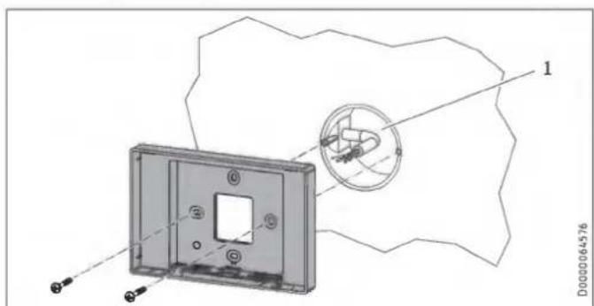
1 Flush box
- Secure the wall mounted enclosure to the flush box or to the wall using the screws provided.
10.6 Electrical connection

WARNING Electrocution
Carry out all electrical connection and installation work in accordance with national and regional regulations.

WARNING Electrocution
The connection to the power supply must be in the form of a permanent connection. Ensure the appliance can be separated from the power supply by an isolator that disconnects all poles with at least 3 mm contact separation.

WARNING Electrocution
Before any work on the appliance, isolate the connecting cables in the control panel.

WARNING Electrocution
Do not install the appliance if it is damaged and there is a risk that live components could be touched.
▶ Check the appliance for external damage.

Property damage
Observe the fuse protection required for the appliance (see chapter "Specification / Data table").

Notice
For the power cable, connections and connecting cables to external control equipment, observe chapter "Electrical connection" and the wiring diagram in chapter "Specification".
▶ Take the power consumption of the preheating coil into consideration.

X1 Power supply
X11 Programming unit (Safety extra low voltage)
X18 Window contact (potential-free)
X19 No function
X20 Intensive ventilation (potential-free)
| 4-pin female connector | Safety extra low voltage |
| X11-1 | SDA |
| X11-2 | +5 V DC |
| X11-3 | GND |
| X11-4 | SCL |
Power supply
The appliance is delivered with a power cable without plug.
Strain relief casing

Notice
Never place the half shells of the strain relief casing together before you have prepared the cable and connected the plug.
| Line cross-section | mm^2 | 0.25 - 1.5 |
| Sheath diameter | mm | 4.5 - 8 |
| Insulation stripping length | mm | 9 |
▶ Prepare the end of the cable by stripping the sheath and insulation.
▶ Push the wires into the side of the plug labelled with the terminal assignment. If necessary, press a screwdriver on the clamping springs to make it easier to insert the wires.
▶ Carefully put the plug into the flat insulation semi-shell of the strain relief casing so that the terminal labelling remains visible. The locking tabs on the sides of the plug must engage in the top tabs of the strain relief casing.
▶ Make sure that the strain relief gutter is inserted in the upper insulation semi-shell of the strain relief casing.
▶ Push the upper insulation semi-shell carefully onto the lower insulation semi-shell. The locking tabs on the sides of the lower insulation semi-shell must engage in the recesses of the upper insulation semi-shell.
Programming unit
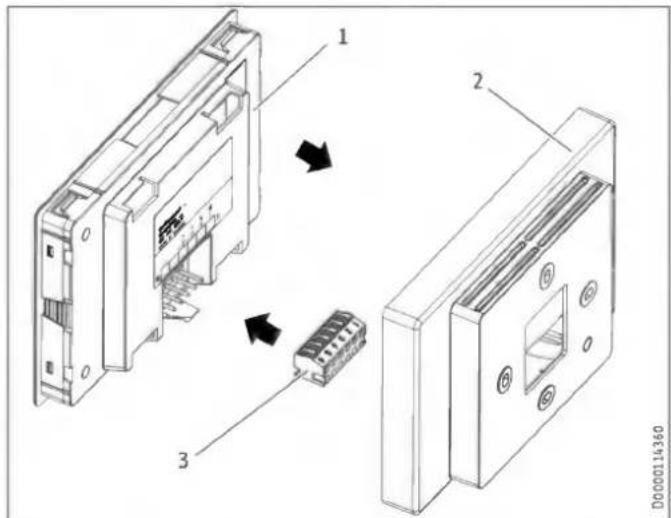
1 Programming unit
2 Wall mounted enclosure
3 6-pin female connector
▶ Connect the bus cable to the ventilation unit.
▶ Connect the bus cable to the female connector.
| Safety extra low voltage | 6-pin female connector |
| Not assigned | 1 |
| Not assigned | 2 |
| GND | 3 |
| +5 V DC | 4 |
| SDA | 5 |
| SCL | 6 |
▶ Connect the female connector to the back of the programming unit.
▶ Click the programming unit carefully into place in the wall mounted enclosure.
Safety equipment for stove/fireplace operation
▶ Install the safety equipment in such a way that it interrupts the appliance power supply when required.
Intensive ventilation switching contact
You can connect a floating switching contact, the actuation of which switches the appliance to intensive ventilation. You can set the runtime for intensive ventilation in the "Intens. vent. time" parameter. After this time has expired, the unit switches back to the previously selected fan setting.
▶ Connect the external pushbutton to terminals 13/14.
Window contact
You can connect a window contact to terminal X18. The window contact is required for bypass mode. The appliance checks whether a window contact is connected and activated at X18.
The window contact must be an N/O contact.
For wall mounting: Short-circuit the internal float switch
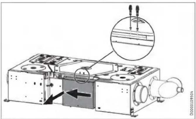
▶ Undo both screws on the top of the control panel cover.
▶ Slide the control panel cover slightly to the left.
▶ Carefully pull the control panel cover away from the appliance.

▶ Short-circuit the float switch as shown.
If you do not short-circuit the float switch, the appliance will not work and a fault code will be displayed.
10.7 Overflow apertures
Create suitable overflow apertures in the supply air area or overflow area. This is essential, as bypass mode is not possible without it.
10.8 LWZ 130 E-W: Extract air filter
▶ If the appliance is installed below the ceiling, replace the factory-installed extract air filter in the appliance with a filter of the following filter class: ISO Coarse > 60 % (G4)
A filter of this type is part of the standard delivery. The filter replacement procedure is described in the following chapter: "Maintenance, cleaning and care / Filter inspection and replacement"
11. Commissioning

WARNING Injury
If the unit is switched on without the air ducts connected and someone reaches through the air connectors into the unit, there is a risk of injury.
Do not commission the unit until the air ducts are firmly connected to it.

Property damage
Never operate the unit without filters.

Property damage
Never operate the ventilation system if there are high levels of dust inside the building or outside in the immediate vicinity, as this could block the filter. Dust is created by cutting tiles or working with plasterboard, for example.
11.1 Initial start-up
Settings
View
When you enter a four-digit code, additional actual values and parameters become visible, which were previously hidden from the appliance user.
▶ To access actual values and parameters which are reserved for qualified contractors, enter the code "1 0 0 0" for "View". Press "OK".
"Service" is shown on the display, when this is entered correctly.

Notice
After entering the code, switch to the menu by pressing the "MENU" button. If you first switch to the home screen, the parameter block is reactivated.
□ ■ General
□□■ Time/date
□□□■Day
▶ Set the current day of the week (Monday to Sunday).
□□□■ Hour:Minute
▶ Set the current time (00:00 to 23:59).
□□■Language
▶ Set the required language.
Air flow rate
▶ Select the air flow rate for the fan settings under "Air flow rate" with "Flow rate, stage 0" to "Flow rate, stage 3".
Enable fan
The fans are deactivated in the delivered condition.
▶ Set the "Enable fan" parameter to "On".
11.2 Recommissioning
▶ Check whether filters are fitted in the unit. Never operate the unit without filters.
▶ Check whether the condensate drain hose is damaged or kinked.
11.3 Appliance handover
Explain the appliance function to users and familiarise them with how it works.

Notice
Hand over these operating and installation instructions to users for safekeeping. All information in these instructions must be closely observed. The instructions provide information on safety, operation, installation and maintenance of the appliance.
12. Settings

Notice
Observe the operating instructions. It explains which parameters can also be set by the appliance user.
12.1 Menus

Notice
Some parameters are protected by a code. The factory programmed code for qualified contractors is "1 0 0 0".

Notice
The parameters shown in grey can only be adjusted by the service department.
▶ Press the "MENU" button to access the menus from the home screen.
| Menu | Description |
| ■ Info | Information about the actual values of the appliance |
| ■ Diagnostics | Fault messages, operating time, maintenance intervals |
| ■ Programs | Fan program |
| ■ Settings | Adjustable values and functions |
12.1.1 "Info" menu
| ■ Info | Value |
| □■ Bypass status | Off | On |
| □■ Extract air temp. | °C |
| □■ Extract air hum. | % |
| □■ Extract air dew pt | °C |
| □■ Outdoor air temp. | °C |
| □■ Outdoor air hum. | % |
| □■ Outdoor air dew pt | °C |
| □■ Supply air temp. | °C |
| □■ Exhaust air temperature | °C |
| □■ Supply air fan control | % |
| □■ Supply air fan speed | rpm |
| □■ Supply air flow rate | m^3/h |
| □■ Exhaust air fan control | % |
| □■ Exhaust air fan speed | rpm |
| □■ Exhaust air flow rate | m^3/h |
| □■ Heating coil control | % |
| □■ Extract air diff. press. | Pa |
12.1.2 "Diagnostics" menu
| ■ Diagnostics | Value |
| □■ Notification list | 0-10 |
| □■ Clear notification list | Off | On |
| □■ Filter runtime | h |
| □■ Filter reset | Off | On |
| □■ Filter change interval | d |
| □■ Device operating time | d |
| □■ Fan operating time | d |
■ Diagnostics
□■ Clear notification list
To clear the notification list, set this parameter to "On". Press "OK" to confirm. Afterwards, "Off" is displayed again and the fault messages are deleted.
12.1.3 "Programs" menu
| Programs | Value |
| Fan program | Monday |
| Tuesday | |
| Wednesday | |
| Thursday | |
| Friday | |
| Saturday | |
| Sunday | |
| Monday - Friday | |
| Saturday - Sunday | |
| Monday - Sunday |
12.1.4 "Settings" menu
| Settings | Value |
| □■ View | Code for qualified contractor |
| □■ General | |
| □□■ Time/date | Day |
| Hour:Minute | |
| □□■ Language | Deutsch |
| English | |
| Francais | |
| Nederlands | |
| Italiano | |
| Polski | |
| Cesky | |
| Magyar | |
| Slovensko | |
| 中文 | |
| Slovensky | |
| 日本語 | |
| □□■ Contrast | 1 - 10 |
| □□■ Brightness | % |
| □□■ Touch sensitivity | 1 - 10 |
| □□■ Touch boost | |
| □□■ Prog. unit software | |
| □■ Air flow rate | |
| □□■ Flow rate, stage 0 | m^3/h |
| □□■ Flow rate, stage 1 | m^3/h |
| □□■ Flow rate, stage 2 | m^3/h |
| □□■ Flow rate, stage 3 | m^3/h |
| □□■ Supply air flow rate offset | m^3/h |
| □■ Favourites | F1, F2, F3 |
| □□■ F1 | Bypass status |
| F2 | Extract air temp. |
| F3 | Extract air hum. |
| Filter runtime | |
| Device software version | |
| Device software patch | |
| Mobile device serial no. | |
| □■ Humidity prot. | Only for qualified contractors |
| □□■ Enable humidity control | Off |
| On | |
| □□■ Humidity prot. interval | h |
| □□■ Humidity threshold | % |
| □□■ Humidity capture delay | min |
| □■ Intensive ventilation | |
| □□■ Intens. vent. time | min |
| □■ Heat recovery bypass | |
| □□■ Set room temperature | °C |
| □□■ Operating mode heat recovery bypass | Disabled |
| Bypass/window contact | |
| Outdoor air routing automatic | |
| Extract air routing autom. | |
| □□■ Temperature to enable heat recovery bypass | °C |
| □□■ Temperature to block heat recovery bypass | °C |
| □□■ Hysteresis for heat recovery bypass | K |
| □□■ Temp. differential for heat recovery bypass | K |
| □□■ Window contact mode (A2)(depending on unit) | Without window contact |
| With window contact | |
| □□■ Cooling/heating, heat recovery bypass | Cooling/heating |
| Cooling | |
| Heating | |
| □■ Frost protection | Only for qualified contractors |
| □□■ Frost protection temperature | °C |
| □□■ Temp. to enable frost protection (A2) | °C |
| □□■ Enable preheating | Off |
| On |
□■ Condensate prevention (A2)
| □□■ Enable condensate prevention | Off |
| On | |
| □□■ Offset condensate prevention | K |
| □■ Enable fan | Off |
| On | |
| □■ Ventilation unit | |
| □□■ Device software version | |
| □□■ Device software patch | |
| □□■ Mobile device serial no. | |
| □□■ Device type |
Settings
□ View
| Effect | |
| Standard (A0) | The only parameters displayed are those that have been released for the appliance user and can therefore be accessed without a code. |
| Service (A1) | Parameters for qualified contractors: Code "1 0 0 0" |
| Expert (A2) | Parameters for service department. |
To access actual values and parameters which are reserved for qualified contractors, enter the code "1 0 0 0" for "View". Press "OK".
"Service" is shown on the display, when this is entered correctly. If you switch to the actual values or parameters, you see the enabled parameters.

Notice
After entering the code, switch to the menu by pressing the "MENU" button. If you first switch to the home screen, the parameter block is reactivated.
Air flow rate
□□■ Supply air flow rate offset
Use this parameter to adjust the supply air flow rate during commissioning. The offset refers to standard ventilation and is converted internally as a percentage for the other fan stages.
Example
| Nominal flow rate (stage 2) | m^3/h | 180 |
| Offset | m^3/h | 45 |
| Stage | Set flow rate | Off-set | Set flow rate + offset | Offset factor | internal set flow rate = set flow rate * offset factor |
| 0 | 50 | 50*1.25 = 62 | |||
| 1 | 130 | 130*1.25 = 162 | |||
| 2 | 180 | 45 | 180+45 = 225 | 225/180 = 1.25 | 180*1.25 = 225 |
| 3 | 235 | 235*1.25 = 294 |
□■ Humidity prot.
□□■ Enable humidity control
With humidity-dependent flow rate control, the air flow rate is increased or decreased depending on the humidity level.
| Parameter | Effect |
| Off | inactive |
| On | active |
□□■ Humidity prot. interval
If you set fan stage 0, the appliance switches to a 24 hour dormant phase. Only after this will humidity protection control start.
The unit measures the humidity of the extract air for the time set for "Humidity capture delay". The appliance compares the last measured value with the limit value set for "Humidity threshold". If the humidity threshold is exceeded, the unit starts to ventilate. If the humidity threshold is undershot again, the unit terminates ventilation. At this point, the Humidity prot. intervalstarts again, at the end of which the moisture is measured.
□□■ Humidity capture delay
The unit measures the humidity of the extract air for the time set for "Humidity capture delay". The appliance compares the last measured value with the limit value set for "Humidity threshold".
□ Heat recovery bypass
□□■ Window contact mode (depending on unit)
Setting whether the window contact is relevant for the bypass mode.
| Parameter | Effect |
| Without window contact | The supply air fan is stopped independently of the window contact. |
| With window contact | The window contact is used to determine whether the appliance stops the supply air fan. |
□□■ Temperature to enable heat recovery bypass
To enable checking of the other parameters for bypass mode, the outdoor air temperature must be no less than the value set in this parameter.
□□■ Temperature to block heat recovery bypass
If the outdoor air temperature falls below this blocking temperature, bypass mode is disabled.
□□■ Hysteresis for heat recovery bypass
To make cooling possible, the outdoor air temperature must be cooler than the extract air temperature by the value set in this parameter.
□□■ Temp. differential for heat recovery bypass
Use this parameter to define the temperature differential that must be exceeded for bypass mode to be enabled. For bypass mode to be enabled, the following condition must be met for 60 minutes:
If Operating mode heat recovery bypass: Outdoor air routing automatic
- Set room temperature + Temp. differential for heat recovery bypass < Outdoor air temp.
If Operating mode heat recovery bypass: Extract air routing autom.
- Set room temperature + Temp. differential for heat recovery bypass < Extract air temp.
□■Frost protection
□□■ Temp. to enable frost protection
The unit only activates frost protection if the outdoor air temperature drops to the value that can be set in this parameter.
□ □ ■ Enable preheating
| Parameter | Effect |
| Off | The internal preheater is completely deactivated. |
| On | The internal preheater is activated. To keep the heat exchanger free from ice, preheating ensures a minimum supply air temperature with reference to the temperature, which can be set in the "Frost protection temp." parameter. |
While this parameter is being displayed or adjusted, the "frost protection" symbol is shown on the display.
□■ Condensate prevention
□□■ Enable condensate prevention
The Condensate prevention function is intended for units without an enthalpy heat exchanger in areas with a subtropical climate.
If the unit is in ventilation mode, and this parameter has the value "On", the unit checks the following conditions:
- Outdoor air temp. > Extract air temp.
- Extract air temp. + Offset condensate prevention < Outdoor air dew point
If both conditions are met, the unit switches the fans off. After a shutdown, the unit switches on the fans cyclically and checks whether the conditions are still valid or whether ventilation mode can be resumed.
| Interval between measurements | min | 60 |
| Duration of measurement | min | 5 |
□□■ Offset condensate prevention
This parameter changes the shutdown point for Condensate prevention. This allows the fans to be switched off 2 K before the dew point temperature is reached, for example.
□ ■ Ventilation unit
□□■ Device type
This parameter is set at the factory. The parameter can only be set after the controller assembly has been replaced.
12.2 Direct selection parameters

Notice
The parameters shown in grey can only be adjusted by the service department.
| Description | Code level | Unit | LWZ 130 | Options | Stand-ard | LWZ 130 Enthalpie, LWZ 130 E-W | ||||||
| Min. | Max. | Min. | Max. | Options | Stand-ard | |||||||
| P1 | Set room temperature | A0 | °C | 5 | 28 | 20 | 5 | 28 | 20 | |||
| P2 | Intens. vent. time | A0 | min. | 1 | 240 | 30 | 1 | 240 | 30 | |||
| P3 | Operating mode heat recovery bypass | A0 | Disabled (0) | Bypass/window contact (1) | Outdoor air routing automatic (2) | Extract air rout-ing autom. (3) | (2) | Disabled (0) | Bypass/window contact (1) | Outdoor air routing automatic (2) | Extract air rout-ing autom. (3) | (2) | ||||||
| P4 | Filter reset | A0 | Off | On | Off | Off | On | Off | ||||||
| P6 | Flow rate, stage 0 | A1 | m3/h | 50 | 100 | 50 | 50 | 100 | 50 | |||
| P7 | Flow rate, stage 1 | A1 | m3/h | 50 | 180 | 90 | 50 | 180 | 90 | |||
| P8 | Flow rate, stage 2 | A1 | m3/h | 50 | 180 | 125 | 50 | 180 | 125 | |||
| P9 | Flow rate, stage 3 | A1 | m3/h | 110 | 180 | 180 | 110 | 180 | 180 | |||
| P14 | Supply air flow rate offset | A1 | m3/h | -100 | 100 | 0 | -100 | 100 | 0 | |||
| P15 | Humidity prot. interval | A1 | h | 1 | 24 | 1 | 1 | 24 | 1 | |||
| P16 | Humidity capture delay | A1 | min | 5 | 15 | 5 | 5 | 15 | 5 | |||
| P17 | Humidity threshold | A1 | % | 5 | 95 | 65 | 5 | 95 | 65 | |||
| P18 | Frost protection temperature | A1 | °C | -5 | 15.0 | 2 | -5 | 15.0 | 2 | |||
| P19 | Filter change interval | A1 | d | 1 | 365 | 90 | 1 | 365 | 90 | |||
| P22 | Enable preheating | A1 | Off | On | On | Off | On | On | ||||||
| P24 | Temperature to enable heat recov-ery bypass | A1 | °C | 5.0 | 15.0 | 10.0 | 5.0 | 15.0 | 10.0 | |||
| P25 | Temperature to block heat recovery bypass | A1 | °C | 5.0 | 15.0 | 8.0 | 5.0 | 15.0 | 8.0 | |||
| P26 | Hysteresis for heat recovery bypass | A1 | K | 0.0 | 5.0 | 2.0 | 0.0 | 5.0 | 2.0 | |||
| P27 | Temp. differential for heat recovery bypass | A1 | K | 0.0 | 5.0 | 2.0 | 0.0 | 5.0 | 2.0 | |||
| P28 | Enable fan | A0 | Off | On | Off | Off | On | Off | ||||||
| P29 | Device type | A1 | 3 | 4 | ||||||||
| P30 | Temp. to enable frost protection | A2 | °C | -10.0 | 5.0 | -3.0 | -10.0 | 5.0 | -3.0 | |||
| P31 | Enable humidity control | A1 | Off | On | Off | Off | On | On | ||||||
| P32 | Enable condensate prevention | A2 | Off | On | Off | Off | On | Off | ||||||
| P33 | Offset condensate prevention | A2 | K | -5.0 | 5.0 | 0.0 | -5.0 | 5.0 | 0.0 | |||
| P34 | Window contact mode (depending on unit) | A2 | without window contact (0) | with window contact (1) | (1) | without window contact (0) | with window contact (1) | (1) | ||||||
| P35 | Cooling/heating, heat recovery bypass | A0 | Cooling/heating (1) | Cooling (2) | Heating (3) | (1) | Cooling/heating (1) | Cooling (2) | Heating (3) | (1) | ||||||
| P70 | Clear notification list | A1 | Off | On | Off | Off | On | Off | ||||||
| P80 | Day | A0 | ||||||||||
| P81 | Time | A0 | 00:00 | 23:59 | 00:00 | 23:59 | ||||||
13. Shutting down the system
We recommend running the appliance in fan stage 1, even during prolonged absence.

Property damage
If you interrupt the power supply to the appliance, check that humidity protection is ensured for the building.
If the appliance needs to be taken out of use for an extended period, disconnect it from the power supply.
▶ Replace the filters.
14. Maintenance

WARNING Electrocution
Disconnect the appliance from the power supply before carrying out work inside the appliance.
▶ Isolate the appliance from the power supply.
| Activity | Maintenance interval (in years) |
| Cleaning the condensate pan | 1 |
| Cleaning the condensate drain | 1 |
| Cleaning the cross-countercurrent heat exchanger | 3 |
| Cleaning the fans | 3 |
| Cleaning the preheater | 2 |
| Cleaning the air ducts | 3 |
▶ Open the cover beneath the appliance or remove the suspended ceiling panels under the appliance.
▶ Disconnect the appliance from the power supply and secure it against unauthorised reconnection.
Cleaning the condensate pan
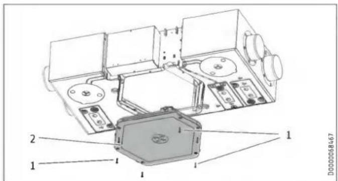
1 Condensate pan fixing screws
2 Condensate pan
▶ Undo the fixing screws of the condensate pan.
▶ Remove the condensate pan from the appliance carefully as it may still contain water.
▶ Clean the condensate pan.
Cleaning the condensate drain

Property damage
A blocked condensate drain can cause appliance faults. If the condensate drain is blocked, condensate can escape from the appliance in an uncontrolled manner and cause water damage.
▶ Clean the condensate drain at regular intervals.
Cleaning the float module of the condensate pump
This section is not necessary if no condensate pump is connected.
▶ Check the functionality of the float module every two years. If necessary, clean the float module.
You can remove the cover of the float module. During assembly, ensure that the bevelled side of the float magnet faces upwards.
▶ Push the cover back onto the float module.
Cleaning the cross-countercurrent heat exchanger
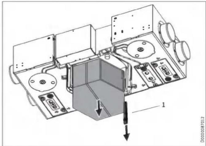
1 Wedge

CAUTION Injury
After the wedge has been removed, the cross-counter-current heat exchanger may become detached and fall down.
▶ When you remove the wedge, you must also remove the cross-countercurrent heat exchanger.
▶ Remove the wedge from between the appliance body and the cross-countercurrent heat exchanger.
▶ Carefully remove the heat exchanger from the appliance. Do not let it fall. Avoid damaging the EPS parts in the appliance.
▶ Use a commercially available vacuum cleaner to remove dust and other loose dirt particles from the intake and discharge surfaces.
▶ If required, clean the heat exchanger with warm water (max. 55 °C) and a commercially available detergent. Do not use solvents.
▶ Flush the heat exchanger with water.
Cleaning the fans
You can clean the fans without disconnecting the cables leading to the fans. Nevertheless, we recommend removing the control panel cover. Then you can unplug the control cable and power cable from the printed circuit board.
▶ Undo the screws securing the fans.
▶ Clean the fans with a soft brush.
Cleaning the preheater
In principle, the preheater does not need to be cleaned. Inadequate filter changing can cause dust to build up in the appliance. In this case, the preheater does need to be cleaned.
Refitting the components
▶ Push the fan units back into the appliance.
▶ Reconnect the fan cables.
▶ Fit the control panel cover.
▶ Slide the cross-countercurrent heat exchanger back into the appliance.
▶ Push the wedge back in again.
▶ Fit the condensate pan.
Cleaning the air ducts
Air ducts must be checked at regular intervals and cleaned if necessary. Disconnect the air ducts from the appliance or carry out inspection and cleaning through the extract air and supply air vents.
15. Troubleshooting

WARNING Electrocution
Disconnect the appliance from the power supply before carrying out work inside the appliance.
▶ Disconnect the appliance from the power supply and secure it against unauthorised reconnection.

WARNING Electrocution
The power cable must only be replaced (for example if damaged) by a qualified contractor authorised by the manufacturer, using an original spare part.
Fault (Exxx)
| xxx | Fault | Effect | Remedy |
| --- | No fault present | ||
| 8 | No humidity value for the extract air | The appliance cannot provide humidity protection. | Isolate the appliance from the power supply. Check the sensor cable. Replace the sensor. |
| 10 | No temperature value for the extract air | Bypass mode is not possible with extract air routing. Bypass mode can be manually enabled with the option "Bypass/window contact" in the parameter "Operating mode heat recovery bypass". | Isolate the appliance from the power supply. Check the sensor cable. |
| 11 | No temperature value for the outdoor air | Bypass mode is not possible with outdoor air routing. Bypass mode can be manually enabled with the option "Bypass/window contact" in the parameter "Operating mode heat recovery bypass". | Isolate the appliance from the power supply. Check the sensor cable. |
| 16 | The condensate float switch has responded. | The unit switches off the fans. | Check the condensate drain. Check the cable for breakages. |
| 17 | Outdoor air temperature sensor short circuit | No control to the comfort temperature required for passive houses of at least 16.5 °C in the supply air | Isolate the appliance from the power supply. Check the sensor cable. |
| 18 | Outdoor air temperature sensor lead break | No control to the comfort temperature required for passive houses of at least 16.5 °C in the supply air | Isolate the appliance from the power supply. Check the sensor cable. |
| 101 | Supply air fan | The unit does not receive any speed feedback from the fan. There is no effect on the flow rate control mode. | Isolate the appliance from the power supply. Check the cabling. Check the PWM control signal that the electronic assembly sends to the fan. Check the speed signal that the fan sends to the electronic assembly. Replace the fan. |
| xxx | Fault | Effect | Remedy |
| 102 | Exhaust air fan | The unit does not receive any speed feedback from the fan. There is no effect on the flow rate control mode. | Isolate the appliance from the power supply. Check the cabling. Check the PWM control signal that the electronic assembly sends to the fan. Check the speed signal that the fan sends to the electronic assembly. Replace the fan. |
| 105 | Maximum outdoor air temperature exceeded | The high limit safety cut-out may respond. | Isolate the appliance from the power supply. Check the air flow rate. Check the triac for continuity. Check the sensor cable. |
| 201 | No RTC communication (RTC = real-time clock) | Time-dependent program sequences are disrupted. | Isolate the appliance from the power supply. Replace the electronic assembly. |
| 202 | No RTC pulse | Time-dependent program sequences are disrupted. | Isolate the appliance from the power supply. Replace the electronic assembly. |
| 203 | Sensor voltage too low | The unit controls the fans with the maximum value of the currently selected fan stage. The appliance cannot provide humidity protection. Automatic bypass mode is not possible. Bypass mode can be manually enabled with the options "Disabled" and "Bypass/window contact" in the parameter "Operating mode heat recovery bypass". | Isolate the appliance from the power supply. Check the sensor voltage after disconnecting one of the following sensor plugs: X15, X16, X23, X24. Replace the sensor. Replace the electronic assembly. |
| 204 | Supply air shutdown | If the supply air temperature drops below 5 °C, the fan is switched off. | Check the preheating coil. |
| 205 | Maximum outdoor air temperature exceeded | The high limit safety cut-out may respond. | Isolate the appliance from the power supply. Check the triac for continuity. Check the sensor cable. |
| - | Programming unit does not start. | Parameters cannot be adjusted. | I^2C -connection faulty: Check cable and plug-in connections. Replace damaged cable. |
| - | Set time programs have been deleted. | If the programming unit is replaced, the time programs are deleted. | Set the time programs again. |
16. Disposal
Removal

WARNING Electrocution
Disconnect the appliance from the power supply.
The following tools are required for disassembly and material separation prior to disposal:
- Personal protective equipment
- Set of screwdrivers
- Set of spanners
- Combi pliers
- Stanley knife
17. Specification
17.1 Dimensions and connections
LWZ 130
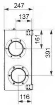
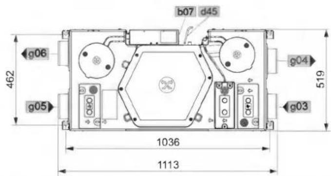
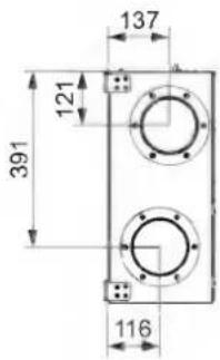
D0000068463
LWZ 130
| b07 Electrical connection | ||||
| d45 Condensate drain | Diameter | mm | 16.5 | |
| g03 Outdoor air | Diameter | mm | 125 | |
| g04 Exhaust air | Diameter | mm | 125 | |
| g05 Extract air | Diameter | mm | 125 | |
| g06 Supply air | Diameter | mm | 125 | |
LWZ 130 Enthalpie
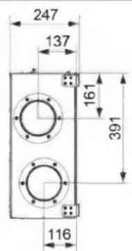

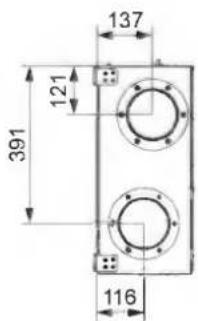
D0000077394
| LWZ 130 Enthalpie | ||||
| b07 | Electrical connection | |||
| g03 | Outdoor air | Diameter | mm | 125 |
| g04 | Exhaust air | Diameter | mm | 125 |
| g05 | Extract air | Diameter | mm | 125 |
| g06 | Supply air | Diameter | mm | 125 |
LWZ 130 E-W

Remote control
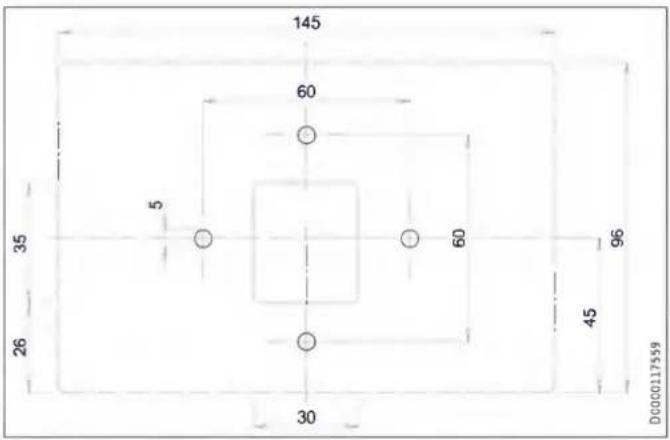
| LWZ 130 E-W | ||||
| b07 | Electrical connection | |||
| d45 | Condensate drain | Diameter | mm | 22 |
| g03 | Outdoor air | Diameter | mm | 125 |
| g04 | Exhaust air | Diameter | mm | 125 |
| g05 | Extract air | Diameter | mm | 125 |
| g06 | Supply air | Diameter | mm | 125 |
17.2 Fan diagram
The graph shows the pressure drop for examples of air distribution systems.
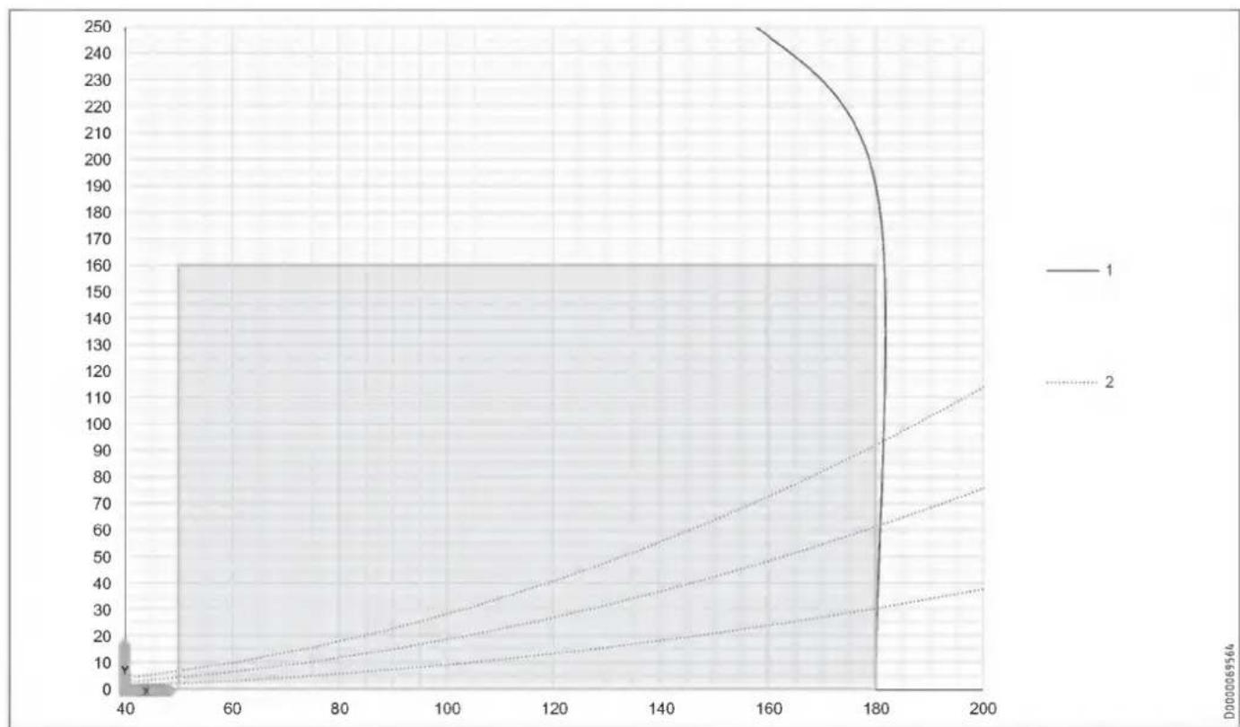
line
| x | y (Line 1) | y (Line 2) | y (Line 3) | | ---- | ---------- | ---------- | ---------- | | 40 | 0 | 0 | 0 | | 60 | 10 | 5 | 3 | | 80 | 20 | 10 | 6 | | 100 | 30 | 15 | 9 | | 120 | 40 | 20 | 12 | | 140 | 50 | 25 | 15 | | 160 | 60 | 30 | 18 | | 180 | 70 | 35 | 21 | | 200 | 80 | 40 | 24 |Application range
X Air flow rate [m^3/h]
Y Average value, static pressure [Pa]
1 Maximum fan curve
2 System curves
17.3 Wiring diagram
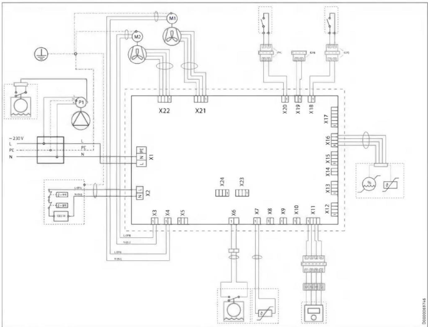
flowchart
graph TD
    A["~230V L PE N"] --> B["P1"]
    B --> C["X22"]
    C --> D["X21"]
    D --> E["X20"]
    E --> F["X19"]
    F --> G["X18"]
    G --> H["X17"]
    H --> I["X16"]
    I --> J["X15"]
    J --> K["X14"]
    K --> L["X13"]
    L --> M["X12"]
    M --> N["X11"]
    N --> O["X10"]
    O --> P["X9"]
    P --> Q["X8"]
    Q --> R["X7"]
    R --> S["X6"]
    S --> T["X5"]
    T --> U["X4"]
    U --> V["X3"]
    V --> W["L1P0A N100kW"]
    W --> X["L1P0B N100kW"]
    X --> Y["L1P0C N100kW"]
    Y --> Z["L1P0D N100kW"]
    Z --> AA["L1P0E N100kW"]
    AA --> AB["L1P0F N100kW"]
    AB --> AC["L1P0G N100kW"]
    AC --> AD["L1P0H N100kW"]
    AD --> AE["L1P0I N100kW"]
    AE --> AF["L1P0J N100kW"]
    AF --> AG["L1P0K N100kW"]
    AG --> AH["L1P0L N100kW"]
    AH --> AI["L1P0M N100kW"]
    AI --> AJ["L1P0N N100kW"]
    AJ --> AK["L1P0O N100kW"]
    AK --> AL["L1P0P N100kW"]
    AL --> AM["L1P0Q N100kW"]
    AM --> AN["L1P0R N100kW"]
    AN --> AO["L1P0S N100kW"]
    AO --> AP["L1P0T N100kW"]
    AP --> AQ["L1P0U N100kW"]
    AQ --> AR["L1P0V N100kW"]
    AR --> AS["L1P0W N100kW"]
    AS --> AT["L1P0X N100kW"]
    AT --> AU["L1P0Y N100kW"]
X1 Power supply
X2 Frost protection heating
X3 Supply air fan power cable
X4 Exhaust air fan power cable
X6 Internal float switch
X7 Outdoor air temperature sensor
X11 Remote control
X16 Extract air temperature and humidity sensor
X18 Window contact
X19 No function
X20 Intensive ventilation switching contact
X21 Exhaust air fan control cable
X22 Supply air fan control cable
17.4 Data table
| LWZ 130 | LWZ 130 Enthalpie | LWZ 130 E-W | ||
| 237805 | 237806 | 204826 | ||
| Sound emissions | ||||
| Sound power level with standard ventilation and 50 Pa, external | dB(A) | 33 | 33 | 33 |
| Sound power level (EN 12102) | dB(A) | 33 | 33 | 33 |
| Application limits | ||||
| Application range, outdoor air (temperature) | °C | -15-40 | -15-40 | -15-40 |
| Application range, extract air (temperature) | °C | 15-35 | 15-35 | 15-35 |
| Energy data | ||||
| Energy efficiency class | A | A | A | |
| Electrical data | ||||
| Rated voltage | V | 230 | 230 | 230 |
| Phases | 1/N/PE | 1/N/PE | 1/N/PE | |
| Frequency | Hz | 50 | 50 | 50 |
| Power consumption incl. preheating coil | A | 5.00 | 5.00 | 5.00 |
| Power consumption excl. preheating coil | A | 0.46 | 0.46 | 0.46 |
| Power consumption incl. preheating coil | W | 1150 | 1150 | 1150 |
| Power consumption excl. preheating coil | W | 105 | 105 | 105 |
| Fuse protection (circuit breaker) | A | 1*B16 | 1*B16 | 1*B16 |
| Max. mains impedance Zmax | Ω | 0.32 | 0.32 | 0.32 |
| Versions | ||||
| Filter class | ePM10 ≥ 50 % (M5) | ISO Coarse > 60 % (G4) | ePM10 ≥ 50 % (M5) | ISO Coarse > 60 % (G4) | ePM1 ≥ 50 % (F7) | ISO Coarse > 60 % (G4) | |
| IP rating | IP20 | IP20 | IP20 | |
| Dimensions | ||||
| Height | mm | 248 | 248 | 240 |
| Width | mm | 520 | 520 | 527 |
| Depth | mm | 1113 | 1113 | 1264 |
| Weights | ||||
| Weight | kg | 18 | 18 | 18 |
| Connections | ||||
| Air connection diameter | mm | 125 | 125 | 125 |
| Condensate connection | mm | 16.50 | 22.00 | |
| Values | ||||
| Heat recovery level up to | % | 94 | 89 | 89 |
| Air flow rate | m3/h | 50-180 | 50-180 | 50-180 |
| Min. ambient conditions, installation room (temperature) | °C | 2 | 2 | 2 |
| Max. ambient conditions, installation room (temperature) | °C | 35 | 35 | 35 |
| Storage and transportation temperature | °C | -15-50 | -15-50 | -15-50 |
| Available external pressure at max. air flow rate | Pa | 160 | 160 | 160 |
| Heat recovery level | % | 89 | 77 | 77 |
Further details
| LWZ 130 | LWZ 130 Enthalpie | LWZ 130 E-W | ||
| 237805 | 237806 | 204826 | ||
| Maximum height for installation | m | 2000 | 2000 | 2000 |
Guarantee
The guarantee conditions of our German companies do not apply to appliances acquired outside of Germany. In countries where our subsidiaries sell our products a guarantee can only be issued by those subsidiaries. Such guarantee is only granted if the subsidiary has issued its own terms of guarantee. No other guarantee will be granted.
We shall not provide any guarantee for appliances acquired in countries where we have no subsidiary to sell our products. This will not affect warranties issued by any importers.
Environment and recycling
▶ Dispose of the appliances and materials after use in accordance with national regulations.

▶ If a crossed-out waste bin is pictured on the appliance, take the appliance to your local waste and recycling centre or nearest retail take-back point for reuse and recycling.
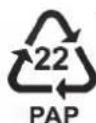
This document is made of recyclable paper.
▶ Dispose of the document at the end of the appliance's life cycle in accordance with national regulations.
Filters in appliance
| Date | Filter dirty | Filter cleaned | Filter changed | ||||
| yes | no | yes | no | yes | no | ||
Filters in extract air/supply air apertures (if present)
| Date | Filter dirty | Filter cleaned | Filter changed | ||||
| yes | no | yes | no | yes | no | ||
REMARQUES PARTICULIÈRES
UTILISATION
natural_image
Four technical floor plan views of a room with mechanical components and fixtures (no text or labels visible)9.2.1 Distances minimales
natural_image
Technical line drawing of a mechanical device with internal components and mounting holes (no text or symbols)natural_image
Technical line drawing of two vehicle components connected by pipes, with a black X mark indicating a specific component (no text or symbols present)natural_image
Technical line drawing of a mechanical device with circular components and a rotating knob (no text or symbols)natural_image
Technical line drawing of a mechanical component with two circular features and a cylindrical shaft (no text or symbols)natural_image
Technical line drawing of a mechanical assembly with flanged components and a circular component (no text or symbols)natural_image
Diagram of a screwdriver inserted into a device, showing mechanical components and directional arrows (no text or symbols)natural_image
Technical diagram of a mechanical assembly with labeled components (no readable text or symbols)1 Clavette

ATTENTION Blessure
natural_image
Top-down architectural floor plan of a four-way mobile room layout with furniture and lighting fixtures (no text or labels)9.2.1 Minimumafstanden
natural_image
Technical line drawing of a mechanical device with internal components and mounting holes (no text or symbols)natural_image
Technical line drawing of two vehicle components connected by pipes, with a black X mark indicating a specific component (no text or symbols present)natural_image
Technical line drawing of a mechanical device with circular components and a rotating knob (no text or symbols)natural_image
Technical line drawing of a mechanical housing or enclosure with two circular components mounted on a base (no text or symbols)natural_image
Technical line drawing of a mechanical assembly with a cylindrical component inserted into a housing (no text or symbols)natural_image
Diagram of a screwdriver inserted into a device, showing mechanical components and directional arrows (no text or symbols)natural_image
Technical diagram showing a device housing with an inset close-up of its internal components (no text or symbols present)1 Inbouwcontactdoos
10.7 Overstroomopeningen
1 Spie

VOORZICHTIG letsel
natural_image
Four technical floor plan views of a room with mechanical components and fixtures (no text or labels visible)9.2.1 Distanze minime
natural_image
Technical line drawing of a mechanical device with internal components and mounting holes (no text or symbols)natural_image
Technical line drawing of two vehicle components connected by a pipe, with no visible text or symbols.| Colore | |
| GN | Ground |
| WH | Neutro |
| BK | Fase |
natural_image
Technical line drawing of a mechanical device with circular components and a rotating knob (no text or symbols)natural_image
Technical line drawing of a mechanical housing or enclosure with two circular components mounted on a rectangular base (no text or symbols)natural_image
Technical line drawing of a mechanical assembly with a cylindrical component inserted into a housing (no text or symbols)natural_image
Diagram of a screwdriver inserted into a device, showing tool movement (no text or symbols)natural_image
Technical diagram of an electronic device interior with labeled components and directional arrows (no readable text or symbols)1 Cuneo

CAUTELA Lesione
natural_image
Top-down architectural floor plan showing four room layouts with furniture and fixtures (no text or labels)natural_image
Technical line drawing of a mechanical device with internal components and mounting holes (no text or symbols)natural_image
Technical line drawing of two vehicle components connected by pipes, with a black X mark indicating a specific component (no text or symbols present)natural_image
Technical line drawing of a mechanical device with circular components and a rotating knob (no text or symbols)natural_image
Technical line drawing of a mechanical housing or enclosure with two circular components mounted inside, no visible text or symbols.natural_image
Technical line drawing of a mechanical assembly with a cylindrical component and flanged housing (no text or symbols)natural_image
Diagram of a screwdriver inserted into a device, showing mechanical components and an arrow indicating insertion direction (no text or symbols)natural_image
Technical diagram of a device housing with an inset close-up showing internal components (no text or symbols)1 Krabice pod omítku
natural_image
Technical diagram of a mechanical device with internal components and an inset close-up view (no text or symbols)natural_image
Four technical floor plan views of a room with mechanical components and fixtures (no text or labels visible)natural_image
Technical line drawing of a mechanical device with internal components and mounting bracket (no text or symbols)natural_image
Technical line drawing of two vehicle components connected by pipes, with a black X mark indicating a specific part (no text or symbols present)natural_image
Technical line drawing of a mechanical device with circular components and a rotating knob (no text or symbols)D0000109503
natural_image
Technical line drawing of a mechanical device with pipe and control panel (no text or symbols)D0000109511
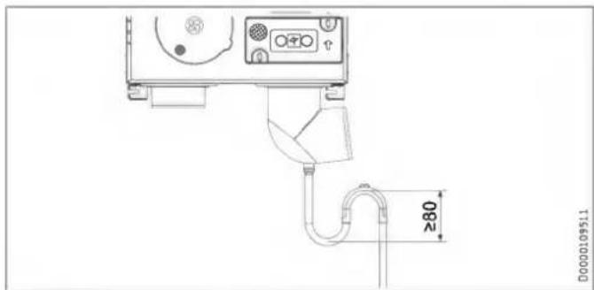
natural_image
Technical line drawing of a mechanical housing or enclosure with two circular components mounted on a base (no text or symbols visible)natural_image
Technical line drawing of a mechanical assembly with a cylindrical component inserted into a housing (no text or symbols)natural_image
Diagram showing a screwdriver inserted into a device with an arrow indicating motion (no text or symbols present)natural_image
Technical diagram of a device housing with an inset close-up showing internal components (no text or symbols)natural_image
Technical diagram of a mechanical assembly with labeled components (no readable text or symbols)natural_image
Four technical schematic diagrams of a mechanical or electrical component layout, no text or symbols present.natural_image
Technical line drawing of a mechanical device with internal components and mounting bracket (no text or symbols)natural_image
Technical line drawing of two vehicle components connected by a pipe, with no visible text or symbols.natural_image
Technical line drawing of a mechanical device with circular components and a rotating knob (no text or symbols)natural_image
Technical line drawing of a mechanical housing or enclosure with two circular components mounted inside, no visible text or symbols.natural_image
Technical line drawing of a mechanical assembly with a cylindrical component and flange (no text or symbols)natural_image
Diagram of a screwdriver inserted into a device with an arrow indicating the process (no text or symbols present)natural_image
Technical diagram of a device mounting bracket with an inset close-up showing internal components (no text or symbols)1 Puszka podtynkowa
natural_image
Technical diagram of a mechanical device with labeled components and directional arrows (no readable text or symbols)1 Klin

natural_image
Four technical floor plan views of a room with mechanical components and fixtures (no text or labels visible)natural_image
Technical line drawing of a mechanical device with internal components and mounting holes (no text or symbols)natural_image
Technical line drawing of two vehicle components connected by pipes, with a black X mark indicating a specific part (no text or symbols present)natural_image
Technical line drawing of a mechanical device with circular components and a rotating knob (no text or symbols)natural_image
Technical line drawing of a mechanical housing or enclosure with two circular components and a cylindrical shaft (no text or symbols)natural_image
Technical line drawing of a mechanical assembly with a cylindrical component and flange (no text or symbols)natural_image
Diagram of a screwdriver inserted into a device, showing mechanical components and an arrow indicating insertion direction (no text or symbols)natural_image
Technical diagram showing a device mounting with an inset close-up view of internal components (no text or symbols)1 Ék

VIGYÁZAT Sérülés
1 Krilni vijak
2 Filtrirna kartuša filtra za odtočni zrak
3 Filtrirna tkanina
4 Rešetka
5 Filtrirna kartuša filtra zunanjega zraka
6 Filter za zunanji zrak
▶ Vijak s krilno glavo na filtrirni kartuši filtra za odtočni zrak odvijte z vrtenjem v nasprotni smeri urinega kazalca.
▶ Filtrirno kartušo izvlecite iz naprave.
▶ Po potrebi v filtrirno kartušo vstavite novi filter. To storite tako, da rešetko, za katero se nahaja filtrirna tkanina, potisnete rahlo na stran in jo kot vrata obrnete naprej.

Materialna škoda
natural_image
Four technical floor plan views of a room with mechanical components and fixtures (no text or labels visible)9.2.1 Minimalni odmiki
Montaža pod strop
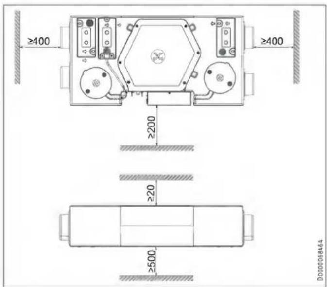
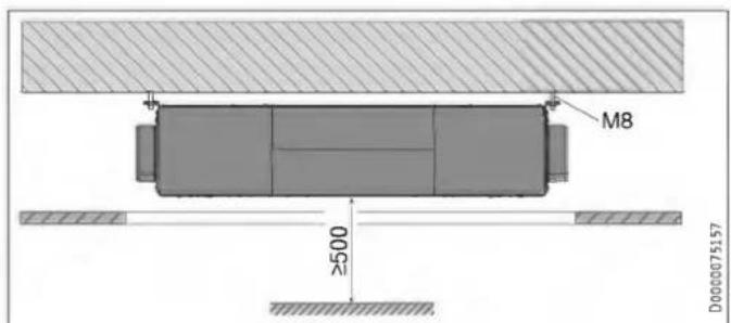
natural_image
Technical line drawing of a mechanical device with internal components and mounting bracket (no text or symbols)natural_image
Technical line drawing of two vehicle components connected by pipes, with a black X mark indicating a specific part (no text or symbols present)natural_image
Technical line drawing of a mechanical device with circular components and a central knob (no text or symbols)D0000109503
D0000109511
▶ Preden priključite gibko cev za odtok kondenzata na napravo, v sifon nalijte vodo.
▶ Cev za odtok kondenzata vgradite s priloženim lovilnim kolenom tako, da nastane sifon z zaporno višino vode najmanj 80 mm.
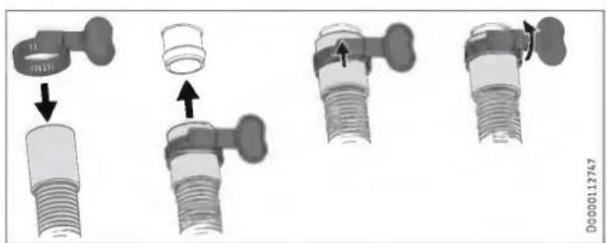
▶ S priloženo cevno objemko pritrdite gibko cev za odtok kondenzata na odtok kondenzata na cevnem kolenu.
10.4 Zračni kanali

Materialna škoda
natural_image
Technical line drawing of a mechanical housing or enclosure with two circular components mounted on a base (no text or symbols)natural_image
Technical line drawing of a mechanical assembly with a cylindrical component and flanged housing (no text or symbols)natural_image
Diagram showing a screwdriver inserted into a device with an arrow indicating motion (no text or symbols present)natural_image
Technical diagram showing a device housing with an inset close-up of its internal components (no text or symbols present)1 Upravljalna enota
2 Stensko ohišje
3 Šestpolni pušni vtič
▶ Vodilo priključite na prezračevalno napravo.
▶ Vodilo priključite v vtičnico.
natural_image
Technical diagram of a mechanical device with internal components and an inset close-up view (no text or symbols)▶ Odvijte vijaka na zgornji strani pokrova stikalne omarice.
▶ Pokrov stikalne omarice potisnite rahlo v levo.
▶ Pokrov stikalne omarice previdno povlecite z naprave.