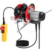
SBS-ET-1000 - Electric lifting device STEINBERG - Free user manual and instructions
Find the device manual for free SBS-ET-1000 STEINBERG in PDF.


| Product type | Electric hoist trolley |
| Model | SBS-ET-1000 |
| Brand | Steinberg |
| Supply voltage | 230 V~ / 50 Hz |
| Rated power | 200 W |
| Maximum load | 999 kg |
| Travel speed | 16 m/min |
| Insulation class | B |
| IP protection rating | IP54 |
| Duty cycle | S3 25% – 10 min |
| Wheel span | 68 – 110 mm |
| Dimensions (L x W x H) | 310 x 300 x 215 mm |
| Weight | 15.3 kg |
| Intended use | Moving loads on monorail (I-beam) |
| Control | Remote control with emergency stop and direction switch |
| Motor | Electric with thermal protection |
| Emergency stop | Red button on remote control |
| Motion limiter | Mechanical limit switch |
| Routine maintenance | Cleaning with soft cloth, regular inspection, gear lubrication |
| Operating ambient temperature | 0 to 40 °C |
| Relative humidity | < 85 % |
| Maximum altitude | < 1000 m |
| Storage conditions | -25 to 55 °C, dry and cool place |
| Included accessories | Remote control, power cable, mounting kit for hoist |
| Repairability | Spare parts list provided, repair by manufacturer's after-sales service |
| Warranty | Contact after-sales service |
Frequently Asked Questions - SBS-ET-1000 STEINBERG
User questions about SBS-ET-1000 STEINBERG
0 question about this device. Answer the ones you know or ask your own.
Ask a new question about this device
Download the instructions for your Electric lifting device in PDF format for free! Find your manual SBS-ET-1000 - STEINBERG and take your electronic device back in hand. On this page are published all the documents necessary for the use of your device. SBS-ET-1000 by STEINBERG.
USER MANUAL SBS-ET-1000 STEINBERG
natural_image
Yellow industrial device with red circular button and black sensor, shown with bidirectional arrow indicator (no text or symbols)LISTE DER BAUTEILE
This User Manual has been translated for your convenience using machine translation. Reasonable efforts have been made to provide an accurate translation; however, no automated translation is perfect nor is it intended to replace human translators. The official User Manual is the English version. Any discrepancies or differences created in the translation are not binding and have no legal effect for compliance or enforcement purposes. If any questions arise related to the accuracy of the information contained in the User Manual, please refer to the English version of those contents which is the official version.
Technical data
| Parameter description Parameter value | |
| Product name | ELECTRIC TROLLEY |
| Model | SBS-ET-1000 |
| Supply voltage [V~] / Frequency [Hz] | 230/50 |
| Rated power [W]. | 200 |
| Maximum load [kg] | 999 |
| Movement speed [m/min] | 16 |
| Insulation class | B |
| IP code | IP54 |
| Work cycle* | S3 25% - 10min |
| Wheel span range [mm] | 68 - 110 |
| Dimensions [width x depth x height; mm] | 310x300x215 |
| Weight [kg] | 15.3 |
The work cycle tells you how long the machine can run in a 10-minute period. For the remainder of this time, the machine should be left unused to allow it to cool down.
1. General overview
This manual is intended to assist you in safe and reliable use. The product is designed and manufactured strictly according to technical specifications using the latest technology and components and maintaining the highest quality standards.
CAREFULLY READ AND UNDERSTAND THIS MANUAL BEFORE STARTING THE WORK.
To ensure long and reliable operation of the device, make sure to operate and maintain it properly in accordance with the guidelines in this instruction manual. The technical data and specifications in this manual are up-to-date. The manufacturer reserves the right to make changes in order to improve the quality. Taking the technical progress and the possibility of reducing noise into account, the unit is designed and built in such a way so that risks resulting from noise emissions are reduced to the lowest possible level.
Explanation of symbols
| CE | The product complies with applicable safety standards. | |
 | Read the manual before use. | |
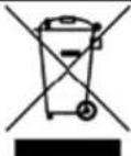 | Recyclable product. | |
 | CAUTION! or WARNING! or REMEMBER! describing a given situation (general warning sign). | |
 | Wear ear protection. Exposure to noise may cause hearing loss. | |
 | Wear protective head gear. | |
 | Wear protective footwear. | |
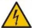 | CAUTION! Risk of electric shock! | |
 | CAUTION! Spinning elements! | |
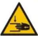 | CAUTION! Danger of crushing your hand!! | |
| CAUTION! Hanging weight! | ||
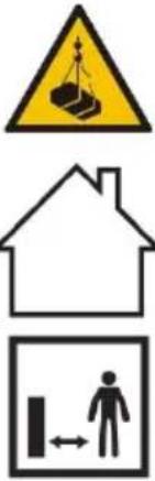 | For indoor use only. | |
| CAUTION! Ensure that bystanders are a safe distance from the work area. | ||

CAUTION! The figures in this manual are illustrative only and may vary in some details from the actual appearance of the product.
2. Safety of use

CAUTION! Read all safety warnings and all instructions. Failure to follow the warnings and instructions may result in electric shock, fire and/or serious injury or death.
The term "device" or "product" in the warnings and in the description of the manual refers to ELECTRIC TROLLEY.
2.1. Electrical safety
a) The plug of this device must fit into the outlet. Do not modify the plug in any way. Original plugs and matching outlets reduce the risk of electric shock.
b) Avoid touching grounded parts, such as pipes, heaters, ovens, and refrigerators. There is an increased risk of electric shock if your body is grounded and touches the device exposed to direct rain, wet pavement, and operation in a humid environment. If water enters the device, there is an increased risk of damage to the unit and electric shock.
c) Do not touch the device with wet or damp hands.
d) Do not use the cord in an unintended manner. Never use it to carry the device or to pull the plug out of the socket. Keep the cord away from heat sources, oil, sharp edges or moving parts. Damaged or tangled cords increase the risk of electric shock.
e) If you cannot avoid using the product in a wet environment, use a residual current device (RCD) to connect it to electrical mains. Using an RCD reduces the risk of electric shock.
f) Do not use the device if the power cord is damaged or shows signs of wear. A damaged power cord should be replaced by a qualified electrician or the manufacturer's service department.
g) To avoid electric shock, do not immerse the cable, plug, or the device itself in water or other liquid. Do not use the appliance on wet surfaces.
h) CAUTION – DANGER TO LIFE! When cleaning or using the appliance, never immerse it in water or other liquids.
i) Do not use the appliance in rooms with very high humidity / in the immediate vicinity of water tanks!
j) The electrical outlet to which the unit will be connected must have a grounding wire.
2.2. Safety in the workplace
a) Keep the work area tidy and well lit. Disorder or poor lighting can lead to accidents. Be foresighted, watch what you are doing and use common sense when using the unit.
b) Do not use the unit in an explosive area, for example in the presence of flammable liquids, gases or dust.
c) If you find any damage or irregularities in the operation of the product, immediately turn it off and report it to an authorized person.
d) If in doubt as to whether the device is working, contact the manufacturer's technical service.
e) Re pairs to the device may only be carried out by the manufacturer's service. Do not attempt to repair the product on your own!
f) In case of open flames or fire, use only dry powder or snow (CO2) fire extinguishers to extinguish the live equipment.
g) No children or unauthorized persons are allowed in the work area. (Inattention may result in loss of control of the unit.)
h) Keep this manual for future reference. If the product is to be handed over to a third party, hand it over with this user manual.
i) Keep packaging components and small installation parts out of the reach of children.
j) Keep the device away from children and animals.
k) When using this product together with other devices, also follow the other instructions for use.

Remember! Keep children and other bystanders safe while operating the equipment.
2.3. Personal safety
a) Do not operate this device if you are tired, ill or under the influence of alcohol, drugs or medication that could impair your ability to operate the device.
b) The unit may be operated by persons who are physically fit, capable of operating it and appropriately trained, and who have read this instruction manual and have been trained in occupational safety and health.
c) The machine is not intended to be used by persons (including children) with reduced mental, sensory or intellectual functions or persons who lack experience and/or knowledge unless they are supervised or have been instructed by a person responsible for their safety on how to operate the machine.
d) Use caution and common sense when operating this device. A moment's inattention during operation may result in serious personal injury.
e) Use personal protective equipment as required when operating the unit as specified in Section 1 of the explanation of symbols. The use of appropriate, approved personal protective equipment reduces the risk of injury.
f) To prevent accidental start-up, make sure the switch is in the off position before connecting to a power source.
g) Do not overestimate your capabilities. Maintain body balance and equilibrium at all times during operation. This allows for better control of the machine in unexpected situations.
h) Do not wear loose clothing or jewelry. Keep hair, clothing, and gloves away from moving parts. Loose clothing, jewelry, or long hair can be caught in moving parts.
i) Before switching the unit on, remove any regulating tools or keys. Any tools or keys left in the rotating part of the unit may cause injury.
j) The product is not a toy. Children should be watched to ensure that they do not play with the appliance.
2.4. Safe use of the device
a) Do not overload the device. Use tools that are suitable for the application. A correctly selected product will do a better and safer job for which it was designed.
b) Do not use the unit if the ON/OFF switch does not function properly (does not turn on and off). Units that cannot be controlled by the switch are unsafe, cannot operate, and must be repaired.
c) Disconnect the device from the power supply before adjusting, cleaning, or servicing. This precaution reduces the risk of accidental start-up.
d) Keep unused product out of the reach of children and anyone unfamiliar with the device or this manual. Products are dangerous when used by inexperienced users.
e) Keep the product in good working order. Check before each use for general damage or damage to moving parts (cracks in parts and components or any other condition that may affect the safe operation of the device). If damaged, have the device repaired before use.
f) Keep the product out of the reach of children.
g) Repairs and maintenance should be carried out by qualified personnel using only original spare parts. This will ensure the safety of use.
h) To ensure the designed operational integrity of the device, do not remove factory-installed covers or loosen screws.
i) When transporting or moving the device from storage to the place of use, observe the health and safety rules for manual handling applicable in the country where the device is used.
j) Avoid situations in which the device stops under heavy loads during operation. This can cause overheating of the drive elements and consequent damage to the equipment.
k) Do not touch any moving parts or accessories unless the device is unplugged.
I) Clean the device regularly to prevent permanent dirt build-up.
m) The product is not a toy. Cleaning and maintenance must not be performed by children without adult supervision.
n) Do not tamper with the device to alter its performance or design.
o) Keep the unit away from sources of fire and heat.
p) Do not block the ventilation openings of the unit!
q) It is forbidden to use the device for carrying loads exceeding its maximum load.
r) Do not allow people or animals to stand under suspended loads.
s) Transporting the load by means of the unit over people or animals is prohibited.
t) Transporting people or animals by means of this unit is prohibited.
u) When transporting with the unit, avoid shocks, impacts and sudden changes in speed. This will reduce the risk of the load falling from a height.
v) Before suspending the load, always ensure that the space in which it will be transported is clear of obstructions.
w) Bystanders should be warned of the operation of the equipment and should stay at a safe distance from the load.
x) Always pay close attention to the load.
y) Do not leave suspended loads unattended.
z) Avoid rocking the load.
aa) Do not perform mechanical or similar work (welding, cutting, etc.) on suspended loads.
bb) Make sure that the load is stable and properly secured on the load ring.
cc) If the load falls, there is a risk of injury or death.
dd) Do not walk or stand under suspended loads (or in their immediate vicinity).
ee) When using the machine, it is forbidden to pull the chain/rope/belt in a direction other than along the track. Pulling sideways may cause damage to the unit
ff) Do not use excessive force and jerk the chain/rope/belt in case of resistance.
gg) The equipment should not be used in corrosive environments, at low ambient temperatures or to transport hot, liquid masses.
hh) Avoid switching on/off sequences at very short intervals.
ii) Make sure that the equipment moves in the direction specified by the controls.
jj) Disconnect the unit from the power supply when not in use.
kk) Do not move loads that are pinned to the ground or blocked by other objects.
II) Loads must be lifted off the ground at the slowest possible speed.
mm) The rope/chain/belt attached to the machine must be held taut when lifting the load.
nn) The I-beam on which the device will move must be in good technical condition and must not have any cracks or deformations.
oo) The permissible load is constant and does not depend on the position in which the load is placed.
pp) The device is not designed for continuous operation. Observe the operating cycle of the device.
qq) If the equipment is used in noisy environments, the operator should wear hearing protection.
rr) The A-weighted sound pressure level at the operator's station is less than 70 dB.
ss) The ambient temperature in the operating area should be between 0-40°C.

CAUTION! Although the product has been designed to be safe, with adequate safeguards, and despite the additional safety features provided to the user, there is still a slight risk of accident or injury when handling the product. Caution and common sense are advised when using the product.
3. Rules of use
The device is designed for transport on a monorail track. It can be used as an anchor point for winches.
The user is responsible for any damage resulting from misuse.
3.1. Product overview
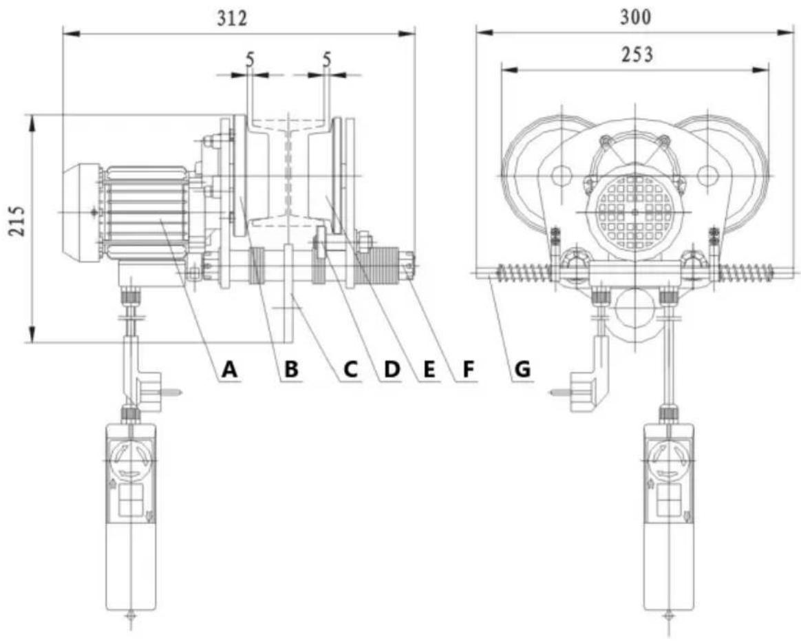
A - Motor
B - Active wheel
C - Plate with a hole for the hook
D - Balance wheel
E - Passive wheel
F - Threaded shaft
G - Movement limiter
3.2. Preparation for operation
ENVIRONMENTAL CONDITIONS
The following table shows the permissible ambient conditions under which the machine can operate safely
| Ambient temperature [°C]. | 0 ~ 40 |
| Relative humidity [%] | < 85 |
| Altitude [m above sea level] | < 1000 |
| Temp. of transport and storage [°C] | -25 ~ 55 |
ASSEMBLY OF THE UNIT
The machine should move on a steel I-beam of the appropriate width.
Make sure that the supporting structure on which the device will move is sufficiently strong. It is forbidden to mount the device on a structure that cannot be verified in terms of its load-bearing capacity. The responsibility for mounting on a support structure and for the support structure itself rests with the user. When placing the device on the supporting structure, special care needs to be taken and all conditions suitable for safe operation must be ensured.
Place the unit in such a way that the mains plug can be reached at any time. Ensure that the power supply to the unit corresponds to that specified on the identification plate!
3.3. Working with the unit
- Measure the width of the rail on which the device is to move.
- The side plates have to be evenly spaced, filling the free spaces on the shafts with spacers. The wheel width of the device (measured between the inner surfaces of the wheel flanges) should be about 4 mm larger than the width of the rail on which it is to move.
- Tighten the hexagonal nuts firmly on both sides of the shafts and secure them with a clip pin.
- Make sure that the unit is properly close to the rail, each wheel rolls freely and maintains good contact with the rail surface, and that the side plates are parallel.
NOTE: Before first use after assembling the device, verify its operation by suspending a light load and rolling the device along the rail several times.
Directions for use
1) The electric motor of the trolley is protected by a thermal switch.
The machine may stop during operation and will not be ready for further operation before cooling down.
2) Do not exceed the maximum load of the machine.
3) Do not use limit switches as routine points for stopping the device from further operation. They are emergency devices only.
4) Make sure the load is properly attached to the hook or block.
5) Always keep a safe distance from the load and the rope.
6) The machine is equipped with additional elements enabling the assembly of the winch. Install the winch on the threaded shafts that connect the side plates.
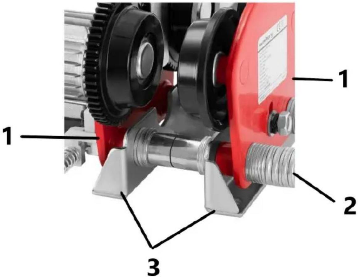
1- Side plate
2- Threaded shaft
3- Elements for mounting the winch
Equipment Controls
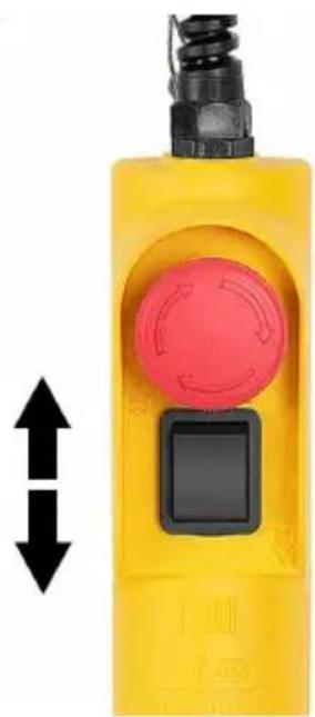
1) Verify that the Emergency Stop If the emergency stop switch is pressed, turn it in the direction of the arrow symbols to allow the machine to operate.
2) Press the switch according to the arrow next to it to start the movement of the trolley. Depending on your orientation towards the machine, the arrows next to the switch will indicate forward or backward (or right or left) movement. Before starting the actual work with the machine, always make sure that the user can predict the direction in which the machine will move.
natural_image
Yellow industrial device with red circular button and black sensor, shown with bidirectional arrow indicator (no text or symbols)3) If the machine encounters an obstacle and the movement limiter pin is pressed in, the limit switch will be activated. The machine will stop and it will not be possible to continue moving towards the obstacle.
4) In an emergency, immediately press the red button (emergency stop button) to stop the machine. It is not possible to operate the machine while the emergency stop switch is depressed.
3.4. Cleaning and maintenance
a) Pull the mains plug and let the unit cool down completely before cleaning, adjusting or replacing accessories and when the unit is not in use.
b) Use only non-corrosive cleaning agents for cleaning the surfaces.
c) After each cleaning, all the parts should be dried well before the unit is used again.
d) Store the unit in a dry and cool place protected from moisture and direct sunlight.
e) Do not spray the unit with a stream of water or immerse it in water.
f) Make sure that no water enters through the ventilation openings in the casing.
g) Clean the ventilation openings with a brush and compressed air.
h) Perform regular inspections of the unit checking technical fitness and any damages.
i) Use a soft cloth for cleaning.
j) Before each use of the machine, check that the emergency stop switch and push button panel are in good working order.
k) Replace damaged or worn parts on an ongoing basis and keep proper maintenance records.
I) Periodically check the technical condition of the power cable and control cables
m) Periodically check the proper functioning of limit switches. The machine should automatically stop when the movement limiter pin meets an obstacle, which will cause it to be pushed in.
n) Periodically lubricate the gears and check the tightness of all bolts.
DISPOSAL OF WASTE APPLIANCES
At the end of its useful life, this product should not be disposed of with normal household waste but should be taken to a collection point for the recycling of electrical and electronic equipment. This is indicated by the symbol on the product, operating instructions or packaging. The materials used in this appliance are recyclable according to their marking. By reuse, recycling or applying other forms of use of waste machines, you make a significant contribution to the protection of our environment.
Your local administration will provide you with information about the appropriate disposal point for used appliances.
WIRING DIAGRAM
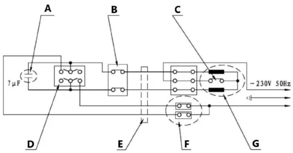
A - Capacitor
B - Emergency stop
C - Overheating protection switch
D - Direction switch
E - Control cable
F - Microswitch
G - Motor
Drawing of the machine - exploded view
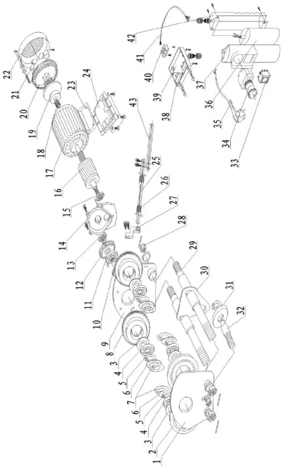
PARTS LIST
| No. | EN | Quantity |
| 1 | Idle wheel side plate | 1 |
| 2 | Passive wheel | 2 |
| 3 | Inner spacer | 4 |
| 4 | Bearing (6204-2RS) | 4 |
| 5 | Shaft locking ring Ø20 | 4 |
| 6 | Outer spacer | 4 |
| 7 | Locking ring for the hole Ø20 | 4 |
| 8 | Driving wheel | 2 |
| 9 | Side plate for the driving wheels | 1 |
| 10 | Gear shaft | 1 |
| 11 | Bearing (6204-ZN) | 4 |
| 12 | Large gear wheel | 1 |
| 13 | Bearing (61900) | 1 |
| 14 | Front cover | 1 |
| 15 | Bearing (6000-2RS) | 2 |
| 16 | Rotor | 1 |
| 17 | Stand | 1 |
| 18 | Spring | 1 |
| 19 | Brake rim | 1 |
| 20 | Gear cover | 1 |
| 21 | Fan blade | 1 |
| 22 | Fan cover | 1 |
| 23 | Housing spacer | 1 |
| 24 | Connecting element of the housing | 1 |
| 25 | Movement limiter | 1 |
| 26 | Limiter spring | 2 |
| 27 | Limiter support | 2 |
| 28 | Crown nut M6x1.5 | 4 |
| 29 | Threaded shaft | 2 |
| 30 | Plate with a hole for the hook | 1 |
| 31 | Balance wheel | 1 |
| 32 | Balance shaft | 1 |
| 33 | Direction switch | 1 |
| 34 | Emergency stop | 1 |
| 35 | Plug | 1 |
| 36 | Capacitor | 1 |
| 37 | Front casing of the remote control | 1 |
| 38 | Microswitch | 2 |
| 39 | Casing | 1 |
| 40 | Terminal block | 1 |
| 41 | Four-core cable | 1 |
| 42 | Back casing of the remote control | 1 |
| 43 | Extension piece for the movement limiter | 2 |

natural_image
Yellow industrial device with red circular button and black base, shown with bidirectional arrow indicator (no text or symbols)LISTA CZĘŚCI
natural_image
Yellow industrial device with red circular button and black sensor, shown with bidirectional arrow indicator (no text or symbols)SEZNAM PRVKÜ
natural_image
Yellow industrial device with red circular button and black base, showing bidirectional arrow indicator (no text or symbols)LISTE D'ÉLÉMENTS
natural_image
Yellow handheld device with red circular button and black top, showing bidirectional arrow (no text or symbols)ELENCO ELEMENTI
natural_image
Yellow handheld device with red circular button and black square button, showing bidirectional arrow (no text or symbols)LISTA DE ELEMENTOS
1- Oldalsó lemez
2- Menetes tengely
natural_image
Yellow industrial device with red circular button and black base, showing bidirectional arrow indicator (no text or symbols)ALKATRÉSZLISTA
natural_image
Yellow industrial device with red circular button and black sensor, shown with bidirectional arrow indicator (no text or symbols)LISTE OVER KOMPONENTER
For the disposal of the device please consider and act according to the national and local rules and regulations.
CONTACT
expondo Polska sp. z o.o. sp. k.
- General overview
- Safety of use
- Electrical safety
- Safety in the workplace
- Personal safety
- Safe use of the device
- Rules of use
- Product overview
- Preparation for operation
- ENVIRONMENTAL CONDITIONS
- ASSEMBLY OF THE UNIT
- Working with the unit
- Directions for use
- Equipment Controls
- Cleaning and maintenance
- DISPOSAL OF WASTE APPLIANCES
- CONTACT
Brand : STEINBERG
Model : SBS-ET-1000
Category : Electric lifting device