NSR-50 - Surveillance Video Recorder SONY - Free user manual and instructions
Find the device manual for free NSR-50 SONY in PDF.

User questions about NSR-50 SONY
0 question about this device. Answer the ones you know or ask your own.
Ask a new question about this device
Download the instructions for your Surveillance Video Recorder in PDF format for free! Find your manual NSR-50 - SONY and take your electronic device back in hand. On this page are published all the documents necessary for the use of your device. NSR-50 by SONY.
USER MANUAL NSR-50 SONY
Network Surveillance Recorder
Installation Manual Page 2 GB
設置説明書 Page 29 JP
System Requirements .... 5
Package Contents 6
Features and Functions 7
Front 7
Rear 9
Installation 11
Installation Without a Rack 11
Rack Mount Installation 12
Connecting a Monitor 14
Connecting the Keyboard, Mouse and Remote Control Unit (RM-NS10) 14
Connecting the Power Cord 14
Connecting the Network Cable 14
Connecting a Network Camera 15
Connecting Other Devices 15
Connecting Remote Client 15
Turn the Power On and Off 16
Turning On the Power 16
Turning Off the Power 16
Basic Configuration 16
Camera IP Address Configuration and Registration to NSR 19
Reconstructing Data Volume (Changing RAID
Types) (Only the NSR-100/50) 21
STATUS LED 23
Miscellaneous 24
LICENSE AGREEMENT 24
Concerning GPL-LPGL 24
MPEG-4 Video Patent Portfolio License ..... 25
Troubleshooting 25
I/O Port 27
Pin Assignment of I/O Port 27
Using the I/O Receptacle 27
Wiring Diagram 1 for Sensor Input ...... 27
Wiring Diagram 2 for Sensor Input ...... 27
Wiring Diagram for Alarm Output 28
©2006 Sony Corporation
Trademarks
- "IPELA" and are trademarks of Sony Corporation.
- Microsoft and Windows are either registered trademarks or trademarks of Microsoft Corporation in the United States and/or other countries.
- Ethernet is a registered trademark of Fuji Xerox Co., Ltd.
- Other products or system names appearing in this document are trademarks or registered trademarks of their respective owners. Further, the ® or ™ symbols are not used in the text.
Before using the recorder, be sure to read this manual.
- Reproduction or duplication, in whole or part, of the software or operation manual supplied with the recorder, as well as renting or leasing of the software without the authorization of the right holder is prohibited under copyright law.
- Sony assumes no responsibility for damages, loss of income, or any claims from a third party arising out of use of the recorder or supplied software.
- For complete terms and conditions of the warranty for the recorder, refer to the warranty card included in the package.
- The software supplied with the recorder cannot be used with any other recorders.
- It is not possible to install any software into the equipment other than the software supplied by Sony specifically for use with the equipment.
- Note that the specifications of the recorder and supplied software are subject to change for improvement without prior notice.
• The recorder uses high security MD5 for password saving.
Disclaimer of liability for recorded content
Sony Corporation does not accept any liability whatsoever for any problems arising from a failure to record, or from damage or erasure of recorded content on this equipment, for any reason. This includes claims for compensation of recorded content, and for any concomitant and consequential damages. Sony Corporation will not repair, restore, or duplicate any recorded content. Your use of this product is subject to these conditions.
Before reading this manual
Be sure to read the "Important Safeguards" supplement.
Usage Precautions
Important Information About Safety
- The electrical specifications of this unit are as follows. Be sure to connect the unit only to a power source that conforms fully to these requirements.
- Voltage: 100 - 127 / 200 - 240 V AC
- Current consumption: 8/4 A
- Line frequency: 50/60 Hz
- Use only the supplied power cord. Do not coil the power cord or bundle it with other cords. Do not piggy back connections. If current ratings are exceeded, there is a risk of fire and other accidents.
- Make sure that all AC outlets and power cords are properly grounded.
- Do not use the unit with the cover or case opened or removed. Otherwise there is a risk of fire and electric shock. Do not attempt to open or remove the cover or case yourself. Always consult your supplier if opening is necessary.
Important Information About Installation
Locations for use/storage
To prolong the life of the product, avoid use or storage in the following locations.
- Locations that can become extremely hot or cold. (The allowable usage temperature range is +5^ to +40^/ +41^ to +104^ .)
- Locations exposed for an extended time to direct sunlight, and locations near heating appliances. (Note that the temperature in a closed car in summer can exceed +50^ / + 122^ .)
- Locations with high levels of humidity or dust
- Locations subject to strong vibrations
- Locations subject to strong magnetic fields
- Locations in the vicinity of radio or TV transmitters creating a strong magnetic field
Do not block the ventilation openings
- The ventilation openings on the sides of the unit serve to prevent internal heat buildup. Always leave a clearance of at least 10cm (4 inches) on both sides as well as behind and above the unit.
- Do not use the unit in a closed box or other enclosure.
- Make sure that there are no cables or other objects in the vicinity of the fan opening on the rear of the unit. If the opening is blocked, internal heat buildup can occur, leading to the risk of fire and damage.
- Also when the unit is installed in a rack, you must make sure that the fan opening on the rear as well as the ventilation openings on the front are not blocked by cables or other objects. Do not install the unit in an environment where the above requirements cannot be met.
Use the unit in a horizontal position
- The unit is designed to be operated in a horizontal position.
- Do not install the unit on a slanted surface, and protect the unit from shocks.
- When the unit is dropped or otherwise subject to strong shocks, it can be seriously damaged.
- When installing the unit in a rack, make sure that a horizontal position is maintained. If the unit is not properly levelled, malfunction may occur. Also, it is highly recommended to properly anchor the rack to a wall or similar, so that it cannot topple over.
Maintenance
- Before cleaning the unit or performing any other kind of maintenance, be sure to disconnect the power cord from the AC outlet.
- For cleaning, lightly wipe the cabinet and panels with a dry cloth. To remove stubborn stains, lightly moisten the cloth with a mild, neutral detergent and wipe with a dry cloth afterwards.
- Do not use cleaning alcohol, solvents, benzine, insecticide, or any other volatile substances, because these may damage the finish and lead to discoloration.
- Dust can accumulate in the ventilation openings on the front of the unit. When removing the dust, make sure that you do not subject the unit to shocks or vibrations.
Transport
Use the original packing material or similar packing to protect the unit from shocks.
Precautions for products with built-in HDD
This unit has a built-in hard disk drive (HDD). The HDD is a precision device. If subject to shock, vibration, static electricity, high temperature or humidity, data loss can occur. When installing and using the unit, closely observe the following precautions.
Protect from shocks and vibrations
When subject to shocks or vibrations, the HDD can be damaged and loss of data on the HDD can occur.
- When transporting the unit, use the specified packing material. When transporting on a dolly or similar, use a type which does not transmit excessive vibrations. Excessive shocks and vibrations can damage the HDD.
- Never move the unit while it is powered. Also before removing or inserting the unit in a rack, make sure that power is off.
- Protect all HDD-equipped devices in the rack from shocks.
- Before removing or inserting the unit in a rack, make sure that power to any other HDD-equipped devices in the rack is also switched off.
- Do not remove panels or outer parts of the unit.
- When placing the unit on a floor or other surface, make sure that the unit is equipped with the specified rubber feet, and put the unit down carefully. If there are no feet, mount the rubber feet first. Do not place the unit near other devices that may become a source of vibrations.
Wait for 30 seconds after turning power off
For a brief interval after the power is turned off, the platters inside the HDD will still keep spinning and the heads will be in an insecure position. During this interval, the unit is more susceptible to shocks and vibrations than during normal operation. For a period of at least 30 seconds after turning power off, avoid subjecting the unit even to very light shocks. After this period, the hard disk will be fully stopped and the unit can be manipulated.
Temperature and humidity related precautions
Use and store the unit only in locations where the specified temperature and humidity ranges are not exceeded.
Temperature range for operation: +5 to +40 °C (+41 to +104 °F)
Humidity range for operation: 20 to 80% relative humidity (maximum wet-bulb temperature 30 °C/86 °F, no condensation)
Temperature range for storage: -20 to +60 °C (-4 to +140 °F)
Humidity range for storage: 20 to 90% relative humidity (maximum wet-bulb temperature 40 °C/104 °F, no condensation)
When HDD seems to be faulty
Even if the HDD is showing signs of malfunction, be sure to observe all the above precautions. This will prevent further damage from occurring until the problem can be diagnosed and corrected.
HDD replacement
The HDD, fan, and battery of the unit are consumable parts that will need periodic replacement. When operating at room temperature, a normal replacement cycle will be about two to three years. However, this represents only a general guideline and does not imply that the life expectancy of these parts is guaranteed. Regarding parts replacement, consult your supplier.
Overview
The NSR series is a hard disk recorder for network cameras. The NSR allows you to monitor and record network camera images (JPEG or MPEG-4). It also allows you to play back the recorded images and search through it, making the NSR a truly versatile monitoring system.
Control compatible cameras from remote locations
You can pan, tilt, and perform zoom operations of compatible cameras.
Compatible with analog cameras
You can monitor and record images from analog cameras when you purchase and install an optional camera server (SNT-V704).
Large-capacity hard disks allow recording for long periods of time
The NSR is equipped with large-capacity hard disks. The NSR-100 can record up to approximately 920 GB ^1) of data, the NSR-50 can record up to approximately 460 GB ^1) of data, and the NSR-25 can record up to approximately 230 GB ^1) of data. For example, if you record images from 16 cameras at 1 fps ^2) VGA, JPEG; one frame equals about 31 KB) with the NSR-100, you can record approximately a month's worth of images (15 hours a day) ^3)
1) Includes the database capacity managed by the internal software.
2) fps: frames per second.
3) When set to RAID 0.
Slim type (2U), space-saving 19-inch rack mounting model
With the optional rack mounting kit (sold separately), the unit can be installed in a standard universal pitch EIA 19-inch rack.
High-resolution up to 480 fps (VGA, JPEG) recording
The NSR-100 can support up to 64 cameras, the NSR-50 can support up to 32 cameras, and the NSR-25 can support up to 20 cameras. The NSR-100 records images at a total frame rate of 480 fps* (240 fps with the NSR-50, 120 fps with the NSR-25), VGA (640 × 480 pixels) resolution, JPEG (1 frame approx. 31 KB) image format, for a crisp image quality.
* Maximum frame rate when 16 cameras are connected to the recorder. Each camera has a frame rate of approximately 30 fps. This frame rate may become less because of fragmentation on the internal hard disks. Values are based on Sony measurements. These values are not guaranteed, as performance may change due to the user's operating environment.
High reliability
The NSR-100/50 performs high reliability through:
• NSR-100: RAID 0, 1+0, and 5
• NSR-50: spanning* and RAID 1
When used with a RAID 1, 1+0 or 5, the system can continue functioning even if one of the hard disks develops a malfunction. Similarly, because the system software and settings are stored on the internal flash memory of the NSR, if the system software develops a malfunction, lightning-quick restoration of the system is possible. The NSR also supports uninterruptible power supplies (UPS)**, making them extremely reliable systems.
* Spanning: Function allowing several hard disks to be virtually seen as one.
** Sony recommendation only.
Notes
- When you use RAID 0 with the NSR-100 or spanning with the NSR-50, there is no data redundancy. Also, storage capacity varies according with the RAID level.
- RAID is not available for the NSR-25.
Other features
- You can display the images from up to 64 cameras (8 × 8 images) on one screen.
- The NSR is capable of manual, scheduled, and alarm recording, among others.
- The NSR is equipped with a motion detection function ^1) (Video Motion Detection (Recorder)).
- Run searches for recorded images by camera name, date, alarm, and other methods.
- Create privacy zones by using the dynamic masking functions ^2) . Dynamic masking covers pan, tilt, and zoom.
- Precise alarm processing is made possible by performing the various types of filtering ^3) that use the image processing results sent from the camera in the form of object information metadata. Because filtering can be applied to metadata that has already been recorded, you can also search for areas of interest after recording is finished.
- Audio recording and playback ^4) are also supported from compatible cameras.
1) Some functions are limited depending on the number of cameras connected.
2) Some functions are limited depending on which camera models are connected.
3) To perform motion detection and object detection using metadata, a camera that supports motion detection by metadata is required. The use of metadata is supported for up to 32 cameras.
4) The optional active speakers are required.
Important
This manual only describes how to install and configure the NSR. For detailed explanations about how to use the recorder, refer to the “User’s Guide” (PDF) on the supplied “NSR Series Manual, Tool & Source Codes CD”.
System Requirements
The hardware required in order to use this recorder are as follows.
- Sony Network cameras
Contact your dealer for details about compatible Sony network cameras. - Monitor ^1)
- USB Keyboard ^2)
• USB Mouse - Network switch
• 1000Base-T/100Base-TX/10Base-T cable - CF (CompactFlash) card or USB memory device ^4)
1) For details about monitors supported by the NSR, contact your retailer. The following “Generic” type monitors can be selected. Frequency is indicated at the end of each line.
- Generic LCD Display; LCD Panel 1024×768; 40-70
- Generic LCD Display; LCD Panel 1280×1024; 50-75
- Generic LCD Display; LCD Panel 1600×1200; 60
- Generic CRT Display; Monitor 1024×768; 50-70
- Generic CRT Display; Monitor 1280×1024; 50-90
- Generic CRT Display; Monitor 1600×1200; 50-90
The following resolutions can be specified.
- XGA (1024×768)
- SXGA (1280×1024)
- UXGA (1600×1200)
2) Use a USB keyboard with a cable. However, keys other than the standard may not function. Wireless or infrared USB keyboards may also not function properly.
3) Use a USB mouse with a cable. However, three-button or wheel mice may not function properly. Wireless or infrared USB mice may also not function properly.
4) Required when backing up system information such as logs.
- For CF, use a card that has been formatted in advance with VFAT.
- For USB memory, use a device that supports general USB Mass Storage Class specifications.
- CF cards are not compatible with the NSR-25.
Package Contents
Check that the following items are included in this package:
• NSR-100, NSR-50, or NSR-25 Surveillance Recorder (1)
- Front panel key (2)
• Installation Guide (this document) (1)
- Remote Control Unit Operation Card (1)
• NSR Series Recovery CD (1)
• NSR Series Manual, Tool & Source Codes CD (1)
- Important Safeguards (1)
- Safety Notice (1)
- Warranty booklet (1)
- Rubber feet (4)
Notes
- This package may contain additional hardware and/or documentation for those options.
- Save the boxes and packing materials for future use.
- The rack mounting kit is optional (sold separately). To order a rack mounting kit, contact your retailer.
- The following are included on the NSR Series Manual, Tool & Source Codes CD.
Manual folder: User's Guide and Remote Control Unit Operation Card data (multilingual)
SourceCode folder: Source code for GPL/LGPL-compliant software
Tool: Remote client software (RealShot Manager), CAM file playback application (Media File Player), and accompanying user's guides
Features and Functions
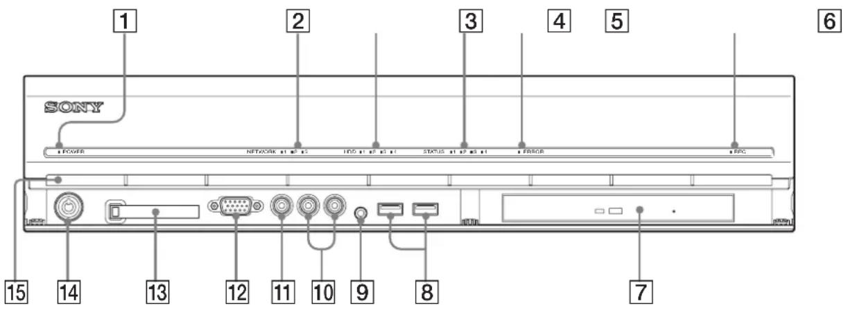
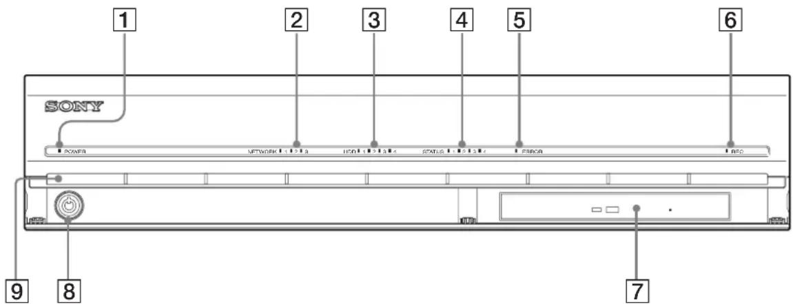
Front
NSR-100/50
text_image
1 SONY POWER NETWORK 11 23 10D 11 24 31 STATUS 11 23 31 ERROR BRC 15 14 13 12 11 10 9 8 71 Power LED
Alternates between green and amber lights when the unit is starting up.
Lights green when startup is complete.
Lights amber when it is on standby.
2 Network LED (1 to 3)
Lights green when there is activity at the corresponding LAN connector at the rear of the NSR.
3 HDD LED
Blinks green when the internal hard disks are accessed. Lights amber when an error occurs with a hard disk.
4 Status LED (1 to 4)
Lights in sequence (1, 2, 3, 4) when the NSR starts. When an error occurs, the corresponding status LED lights together with the error LED, which lights or blinks to indicate the type of error. For details, see “STATUS LED” (page 23).
5 Error LED
Lights or blinks when an error occurs.
6REC LED
Lights when recording images.
7 DVD/CD drive
Use this drive to write data from the NSR hard disks to DVD and CD.
* For details on compatible media, refer to the “User’s Guide” (PDF) on the supplied “NSR Series Manual, Tool & Source Codes CD”.
8 USB connector
Use this connector to connect a USB keyboard, mouse, USB flash memory or the RM-NS10 remote control to the NSR.
9 Audio input connector\*
Use this connector to input audio from a peripheral audio device, such as a microphone.
10 Audio output connectors (L and R)
Use these connectors to output audio to a peripheral audio device.
11 Video output connector
Use this connector to output video to a peripheral video device, such as a VCR. The displayed images are the same as those for monitor connector 1.
12Monitor connector 1
Use this connector to connect a monitor.
13 CompactFlash card slot
Use this slot to save configuration data from the NSR hard disks to a CompactFlash card.
14Lock
Use this in conjunction with the supplied front panel key to lock the front bezel. When the front bezel is locked, you cannot pull out the front bezel. Also, do not lock the front bezel when the front bezel is pulled out. You can distinguish the locked position from the unlocked position by looking at the lock, as illustrated below.
The front bezel is locked

The front bezel is unlocked

15 Vent holes
These openings allow air to flow from the front of the NSR to the rear.
Do not block the vent holes, allow dust to accumulate in the inner mesh of the vent holes, or obstruct the airflow in any way. Obstructing the airflow allows heat to build up inside the NSR and may result in fire or damage.
* This feature is not currently supported.
NSR-25
text_image
1 2 3 4 5 6 SONY POWER NETWORK 1:2:3 USB 1:2:3:4 STATUS 1:2:3:4 LPGA RBO 9 8 71 Power LED
Alternates between green and amber lights when the unit is starting up.
Lights green when startup is complete.
Lights amber when it is on standby.
2 Network LED
Lights green when there is activity at the corresponding LAN connector at the rear of the NSR.
3 HDD LED
Blinks green when the internal hard disks are accessed. Lights amber when an error occurs with a hard disk.
4 Status LED (1 to 4)
Lights in sequence (1, 2, 3, 4) when the NSR starts. When an error occurs, the corresponding status LED lights together with the error LED, which lights or blinks to indicate the type of error. For details, see “STATUS LED” (page 23).
5 Error LED
Lights or blinks when an error occurs.
6REC LED
Lights when recording images.
7Combo drive
Use this drive to write data from the NSR hard disks to CD.
8Lock
Use this in conjunction with the supplied front panel key to lock the front bezel. When the front bezel is locked, you cannot pull out the front bezel. Also, do not lock the front bezel when the front bezel is pulled out. You can distinguish the locked position from the unlocked position by looking at the lock, as illustrated below.
The front bezel is locked
The front bezel is unlocked


9 Vent holes
These openings allow air to flow from the front of the NSR to the rear.
Do not block the vent holes, allow dust to accumulate in the inner mesh of the vent holes, or obstruct the airflow in any way. Obstructing the airflow allows heat to build up inside the NSR and may result in fire or damage.
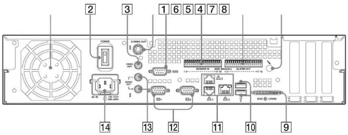
Rear
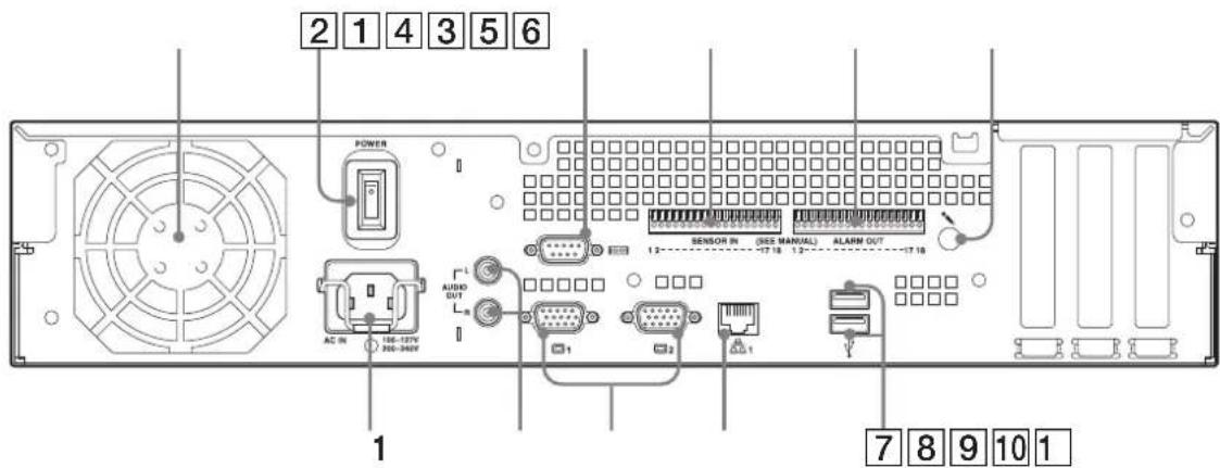
NSR-100/50
text_image
2 3 1 6 5 4 7 8 POWER S VIDEO OUT VIDEO OUT AC IN 108-127V 206-240V 12 13 14 15 16 SENSOR IN (SEE MANUAL) ALAIN OUT -17.18 1.2- 12 13 14 15 16 17 11 12 13 14 15 16 17 10 9 NOSI LV/USE1 Fan
Take care not to obstruct the fan grille. If the grille is obstructed, heat may build up in the unit, leading to damage and/or fire.
2 Power switch
Press the switch in the position to turn on the unit.
③ Video output connector
Use this connector to output video to a peripheral video device, such as a VCR.
The displayed images are the same as those for monitor connector 1.
4 S-video output connector
Use this connector to output video to a peripheral video device equipped with an S-video connector.
The displayed images are the same as those for monitor connector 1.
5 Serial connector (RS-232C)
Use this connector to connect the control line of the uninterruptible power supply (UPS).
6 Sensor input connector
Use this connector to connect the sensor input lines. For connection details and wiring diagrams for sensor inputs, see "I/O Port" (page 27).
7 Alarm output connector
Use this connector to connect the alarm output lines. For connection details and a wiring diagram for alarm output, see "I/O Port" (page 27).
8 Audio input connector\*
Use this connector to input audio from a peripheral audio device, such as a microphone.
9 SCSI connector\*
Use this connector to connect a peripheral SCSI device.
10 USB connector
Use this connector to connect a USB keyboard, mouse, USB flash memory or the RM-NS10 remote control to the NSR.
11 LAN connectors (1 to 3)
Use these connectors to connect 10 Base-T, 100 Base-TX, or 1000 Base-T network cables to the NSR.
LAN1: Network cameras
LAN2: Remote Clients
LAN3: External storage devices**
12 Monitor connectors (1 and 2)
Use these connectors to connect a monitor.
13 Audio output connectors (L and R)
Use these connectors to output audio to a peripheral audio device.
14 Power supply connector
Use this connector to connect the power cord.
* This feature is not currently supported.
** The external storage device is not supported depending on the software version. Consult your dealer.
NSR-25
text_image
2 1 4 3 5 6 POWER AC IN 106-127V 200-349V L AUDIO OUT 1 SENSOR IN (ISS MANUAL) ALARM OUT 12 12 12 1 1 7 8 9 10 11Fan
Take care not to obstruct the fan grille. If the grille is obstructed, heat may build up in the unit, leading to damage and/or fire.
2 Power switch
Press the switch in the O position to turn on the unit.
3 Serial connector (RS-232C)
Use this connector to connect the control line of the uninterruptible power supply (UPS).
4 Sensor input connector
Use this connector to connect the sensor input lines. For connection details and wiring diagrams for sensor inputs, see "I/O Port" (page 27).
5 Alarm output connector
Use this connector to connect the alarm output lines. For connection details and a wiring diagram for alarm output, see "I/O Port" (page 27).
6 Audio input connector*
Use this connector to input audio from a peripheral audio device, such as a microphone.
7 USB connector
Use this connector to connect a USB keyboard, mouse, USB flash memory or the RM-NS10 remote control to the NSR.
8 LAN connectors
Use these connectors to connect 10 Base-T, 100 Base-TX, or 1000 Base-T network cables to the NSR.
9 Monitor connectors (1 and 2)
Use these connectors to connect a monitor.
10 Audio output connectors (L and R)
Use these connectors to output audio to a peripheral audio device.
11 Power supply connector
Use this connector to connect the power cord.
* This feature is not currently supported.
Installation
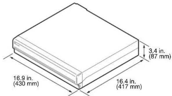
When you are sure that the site chosen to set up the NSR provides appropriate space and strength to support the recorder, connect the AC power cord. The NSR-100 weighs approx. 14 kg (31.1 lb.), the NSR-50 weighs approx. 12 kg (26.7 lb.), and NSR-25 weighs approx. 11 kg (24.2 lb.). The NSR has the following dimensions.
text_image
3.4 in. (87 mm) 16.9 in. (430 mm) 16.4 in. (417 mm)Top
text_image
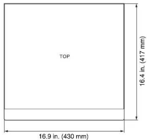
TOP 16.4 in. (417 mm) 16.9 in. (430 mm)When the front bezel is closed
text_image
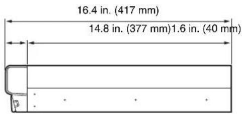
16.4 in. (417 mm) 14.8 in. (377 mm) 1.6 in. (40 mm)When the front bezel is opened
text_image
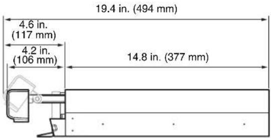
19.4 in. (494 mm) 4.6 in. (117 mm) 4.2 in. (106 mm) 14.8 in. (377 mm)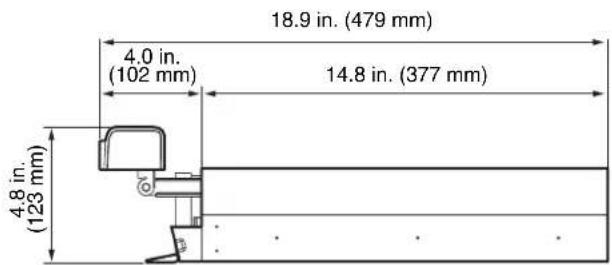
text_image
18.9 in. (479 mm) 4.0 in. (102 mm) 14.8 in. (377 mm) 4.8 in. (123 mm)You can set up the NSR in a rack mount or on a flat surface. If you plan to set it up on a flat surface, you must attach the supplied rubber feet to the bottom of the chassis.
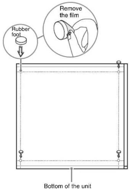
Installation Without a Rack
Attach the provided rubber feet to the recorder. Place the recorder upright so that the bottom surface is visible. Then affix the adhesive surfaces of the rubber feet on the bottom of the recorder as illustrated below.
text_image
Rubber foot Remove the film Bottom of the unitRack Mount Installation
Install the NSR in a rack using the optional rack mounting kit (sold separately).
Warning
- Do not use a rack mounting kit other than the optional mounting kit (sold separately) for the NSR, as doing so is dangerous and may result in fire, shock, or injury.
- If you mount the NSR in a rack, make sure not to place heavy object on it.
- Before mounting the NSR in a rack, we recommend that you mark its intended position in the rack with a felt-tip pen. Mounting the NSR in the rack otherwise than horizontally could result in malfunctions.
• To order a rack mounting kit, contact your retailer.
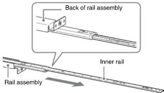
Pulling Out the Inner Rails
Pull out the inner rails from the rail assemblies.
1 Pull out the inner rail from one of the rail assemblies as far as it can go.
text_image
Back of rail assembly Inner rail Rail assembly2 Turn the rail assembly over. As you pull the green tab outward to release the lock, pull the inner rail all the way out.
text_image
Green tab3 Repeat the same procedure with the other rail assembly to pull out its inner rail.
Note
The inner rail will be installed on the NSR, while the rail assembly will be installed on the rack.
Preparing the NSR
Use the supplied fasteners and screws to install the inner rail on the NSR.
1 Use the supplied flat head screws to attach the mounting ears to the front of the side panel.
text_image
Mounting ear Flat head screws2 Use the remaining supplied round head screws to install the rails to the NSR, as illustrated.
text_image
Rail Green tab Round head screwsCaution
Using screws other than the supplied screws may damage the unit. Be sure to use the supplied screws to install the rails.
Preparing the Rack
Install the rails on the rack.
1 Determine where you want to install the rails on the rack. We recommend marking this position with a marker or felt tip pen.
Caution
Rails installed at different heights could result in NSR malfunctions.
2 Install the rails on the rack.
(1) Adjust the length of the rails to match the length of your rack.
natural_image
Technical line drawing of a mechanical rail or conveyor system with directional arrows indicating motion (no text or symbols)(2) Use the supplied truss screws and washers to secure both ends of the rails to the rack.
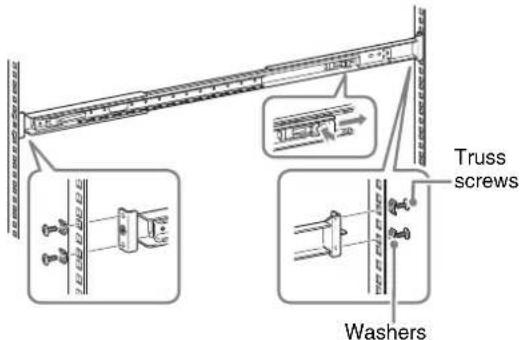
text_image
Truss screws WashersMounting the NSR on the Rack
Insert the NSR into the rack, and then secure it.
Caution
At least two people are needed in order to handle the unit to prevent personal injury.
1 Pull the sliding rails from the rail assemblies.
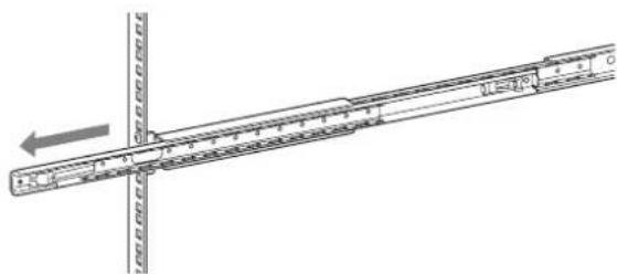
text_image
Technical diagram showing a ruler with measurement markings and an arrow indicating direction, likely for engineering or technical purposes.2 Lift the NSR, fit the inner rails into the slide rail grooves (white), and then slide the assembly until it stops.
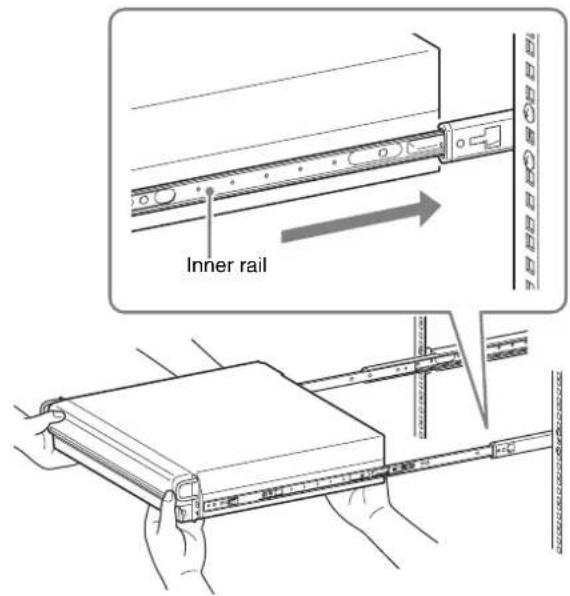
text_image
Inner rail3 As you pull the green tab inward to release the lock, slide the NSR as far as it can go.
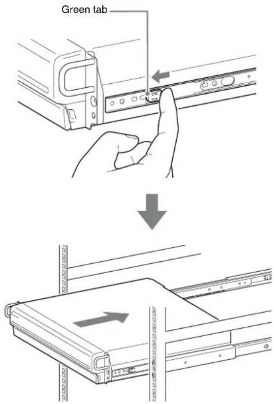
text_image
Green tab4 Use the supplied round head screws to secure the NSR to the rack.
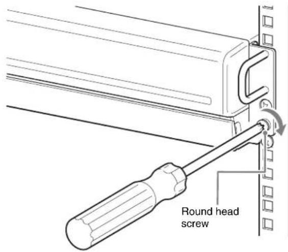
text_image
Round head screw* The remainder of this manual uses illustrations and screens of the NSR-100/50.
Connecting a Monitor
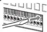
Connect the monitor to the monitor1 connector on the rear of the recorder.

natural_image
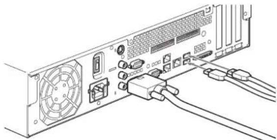
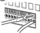
Diagram of a computer drive rear panel with connectors and ports, showing cable connection (no text or labels)Connecting the Keyboard, Mouse and Remote Control Unit (RM-NS10)
1 Connect the keyboard to the USB connector on the rear (or front) of the recorder.
2 Connect the mouse or the remote control unit (RM-NS10) to the USB connector.
natural_image
Line drawing of a computer tower rear panel with connectors and ventilation slots (no text or symbols)Note
When using the NSR-25, only the two USB connectors on the rear of the unit are available. Connecting a keyboard and mouse makes setting up for the first time easier.
Connecting the Power Cord
1 Connect the power cord to the power supply connector at the rear of the NSR, and then connect the other end to the power outlet.
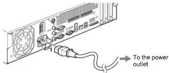
text_image
1 To the power outlet2 Lift the power cord safety clip and snap it around the power cord to prevent it from disconnecting.
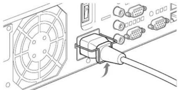
natural_image
Technical illustration of a fan connected to an VGA socket, showing internal components and connection (no text or symbols)Note
Before installing, carefully read “Important Information About Safety” (page 3). When using more than one NSR, also make sure to have sufficient power capacity.
Connecting the Network Cable
Connect the network cable. Connect the one end of the network cable to one of the LAN connectors at the rear of the NSR. Connect the other end to the network switch.

text_image
Diagram of computer motherboard layout showing CPU socket, RAM slots, and ventilation connectorsNote
The default IP address for LAN port 1 is follows;
• LAN connector 1: 192.168.0.1
• LAN connector 2: 192.168.1.1 (only the NSR-100/50)
• LAN connector 3: 192.168.2.1 (only the NSR-100/50)
If you want to change the default IP address, refer to the "User's Guide" (PDF) on the supplied "NSR Series Manual, Tool & Source Codes CD".
Connecting a Network Camera
Use a network cable to connect LAN connector 1 to a network switch, and then connect the desired network camera to the network switch with another network cable.
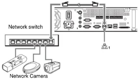
text_image
Network switch Network CameraConnecting Other Devices
Using a CompactFlash Card (Only the NSR-100/50)
Insert your CompactFlash card in the direction illustrated. Make sure that you insert your card with the label side facing up and in the direction of the arrow.
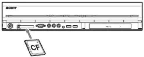
text_image
SOXY CFWhen ejecting a CompactFlash card, press the eject button on the left of the card slot.
Caution
Be careful when ejecting a CompactFlash card, because it may be expelled from the drive energetically.
Connecting an Uninterruptible Power Supply
1 Connect the uninterruptible power source to the power outlet.
2 Connect the NSR to the UPS with the supplied power cord.
3 Connect the NSR to the UPS with the dedicated serial cable to the serial connector on the rear of the NSR.
Connecting Remote Client
If a remote client is required, the supplied RealShot Manager Controller software can be used. RealShot Manager Controller runs on Windows computers. For details on system requirements, refer to the release notes accompanying the RealShot Manager Controller install archive. Also, make sure to use the RealShot Manager supplied with the NSR.
1 Use a network cable to connect LAN connector to a network switch.
When using the NSR-100/50, connect to LAN connector 2 on the unit.
2 Connect the network cable to a computer when RealShot Manager Controller software is installed.
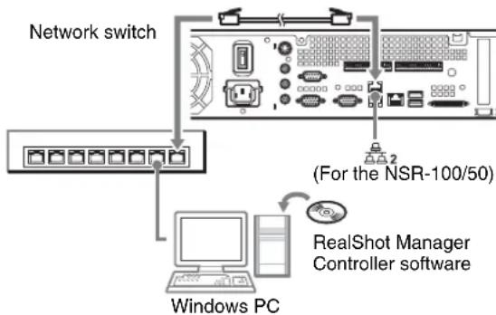
flowchart
graph TD
    A["Network switch"] --> B["Windows PC"]
    B --> C["RealShot Manager Controller software"]
    C --> D["(For the NSR-100/50)"]
Notes
- For details on installation and other topics related to the RealShot Manager Controller software, refer to the supplied NSR Series Manual, Tool & Source Codes CD.
- When using RealShot Manager as a remote controller for the NSR, select [Controller] during installation of RealShot Manager.
- The default connection port for the RealShot Manager server function on the NSR unit is “8081”. The connection port can be changed from the NSR.
- When using the NSR-100/50, use LAN connector 2 at the rear of the NSR even if connecting it to the user area of a network.
Turn the Power On and Off
Turning On the Power
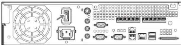
Press the power switch.
natural_image
Back panel diagram showing various electronic components including fan, connector, and power connectors (no text or labels)When startup is complete, the power indicator LED lights green.
Notes
- Immediately (about 2 seconds) after the power is turned on, the cooling fan makes a loud noise. This is normal and not a sign that the unit needs to be serviced.
- When the NSR starts for the first time, the Setup Wizard starts automatically. For details about the setting procedure, refer to the “User’s Guide” (PDF) on the supplied “NSR Series Manual, Tool & Source Codes CD”.
- If the NSR was previously shut down improperly, startup may take longer than usual.
Turning Off the Power
1 Log on to the NSR, and click [System] at the top of the window.
The System Menu screen appears.
2 Click [Shutdown].
A confirmation message appears.
3 Click [OK] to confirm.
The system shuts down, and then the unit shuts down.
Initial Operations (Basic Initial Setup)
Basic Configuration
1 Connect the USB keyboard and USB mouse to the unit, and turn on the power. The following screen appears, and a progress bar for hardware startup appears.

text_image
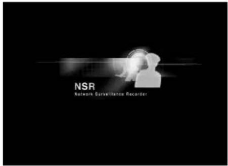
IPELAThen the following screen appears, and a progress bar for software startup appears.
text_image
NSR Network Surveillance RecorderThe unit starts and the system settings screen (Setup Wizard) appears.
2 Click [Next].
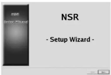
text_image
NSR Setup Wizard - Setup Wizard -The [Select Language] screen appears.
3 Select the desired display language from the list, and then click [Next].
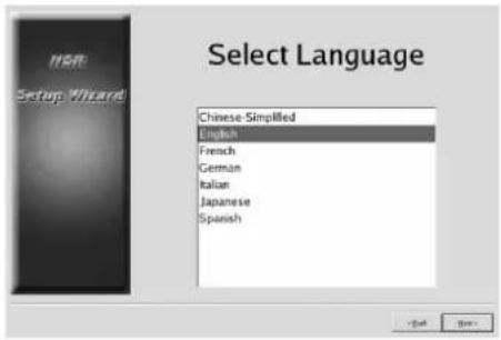
text_image
NSR Setup Wizard Chinese Simplified English French German Italian Japanese SpanishThe [EULA] screen appears.
4 Read the user license agreement, click [Accept], and then click [Next].
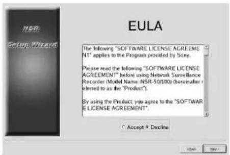
text_image
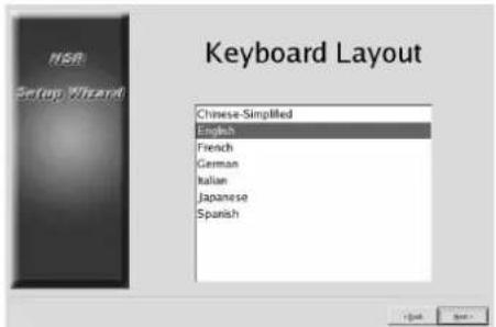
NSR Setup Wizard EULA The following "SOFTWARE LICENSE AGREEMENT" applies to the Program provided by Sony. Please read the following "SOFTWARE LICENSE AGREEMENT" before using Network Surveillance Recorder (Model Name: NSR-50/100) (hereinafter referred to as the "Product"). By using the Product, you agree to the "SOFTWARE LICENSE AGREEMENT". Accept ▼ DeclineThe [Keyboard Layout] screen appears.
5 Select the type of USB keyboard connected to the unit from the list, and then click [Next].
text_image
NSR Setup Wizard Keyboard Layout Chinese-Simplified English French German Italian Japanese SpanishThe [Time Zone] screen appears.
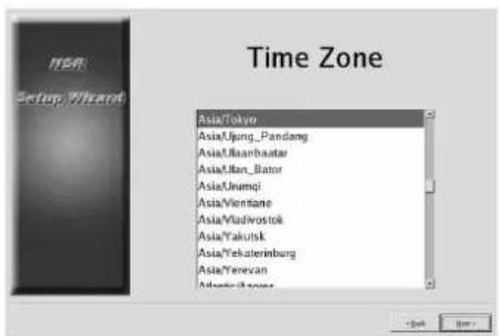
6 Select the desired time zone from the list, and then click [Next].
* There is no option for enabling or disabling summer time. If you select a time zone in which time is adjusted for summer time, the time is adjusted for summer time automatically.
text_image
Time Zone Asia/Tokyo Asia,Ijung_Pandang Asia,Boanbaatar Asia,Man_Bator Asia,Irumqi Asia,Vientiane Asia/Vladwostok Asia,Yakutsk Asia,Yekaterinburg Asia,Yerevan Adventik zoneThe [Date and Time] screen appears.
7 Verify the date and time, and configure the correct date and time if necessary, then click [Next].
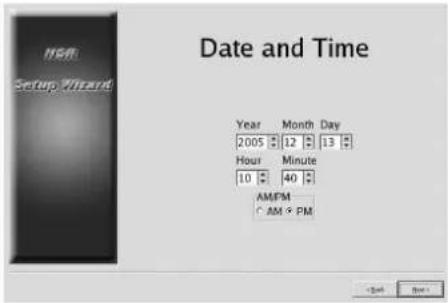
text_image
NSM Setup Wizard Date and Time Year Month Day 2005 12 13 Hour Minute 10 40 AM/FM C AM & PM Clock BackThe [General Network Setting] screen appears.
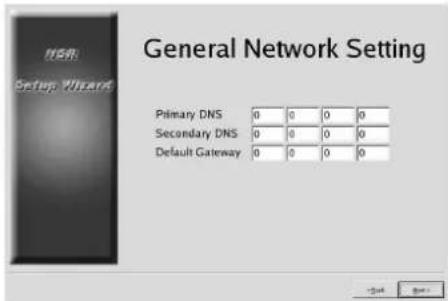
8 Perform the following steps to configure the network settings.
(1) Enter an IP address for each server in the [General Network Setting] screen, and click [Next].
text_image
General Network Setting Primary DNS 0 0 0 0 Secondary DNS 0 0 0 0 Default Gateway 0 0 0 0Primary DNS
Enter the primary DNS (Domain Name Server) IP address.
When there is no primary DNS or one is not necessary, do not enter an IP address.
Secondary DNS
Enter the secondary DNS IP address.
When there is no secondary DNS or one is not necessary, do not enter an IP address.
Default Gateway
Enter the default gateway IP address.
When only the local network is used or connection to other networks is not necessary, do not enter an IP address.
The [Network Device #1] screen appears.
(2) Configure the [Network Device] settings for each of the LAN ports.
When using the NSR-100/50, configure the settings for each of the three LAN ports (LAN1, LAN2, and LAN 3).
When using the NSR-25, configure the settings for the single LAN port (LAN1).
Configure the settings according to the operation environment, and click [Next] for each of the settings screen.
Note
When using the NSR-100/50, connect the following devices to each of the LAN ports.
LAN1: Network cameras
LAN2: Remote clients
LAN3: External storage devices (This may not be supported depending on the software version. For details, consult your dealer.)
text_image
Network Device #1 DHCP * Static IP Address 192 168 0 1 Netmask 255 255 255 0When using a DHCP server to configure address settings automatically Select [DHCP].
When configuring addresses manually
(1) Select [Static].
(2) Enter the following information.
IP Address
Enter the desired IP address.
Caution
- Before you enter the desired IP address, make sure that it is not already otherwise used on the network. Entering an IP address already in use may lead to erratic operation of the unit, but no error messages appear to indicate the fact.
- Because of IP address attribution rules, setting an invalid address such as the ones below is not allowed.
Example: 224.0.0.0 to 255.255.255.255 0.0.0.0 127.0.0.1, etc.
Netmask
Enter the subnet mask address.
Note
The default settings for network devices are as follows.
IP Address: 192.168.[0/1/2]*.1
Netmask: 255.255.255.0
* The settings for each of the network devices #1, #2, and #3 (only network device #1 for the NSR-25).
The [Monitor Model] screen appears.
9
Perform screen size settings depending on each monitor port, and then click [Next].
When two monitors are connected, clicking [Dual Head] displays the second monitor configuration screen.
Select the appropriate monitor type and resolution (pixels) for your monitor.
text_image
Monitor #1 Model P Generic Monitor □ Dual Head General LCD Display: LCD Panel 100x1289.0 315 Generic CRT Display: Monitor 1024x768.0 315.57 Generic CRT Display: Monitor 100x1024.0 315.57 □ Others New Access: APX/10.216.54.0, 50.0-118.8 New Access: APX/10.216.54.0, 50.0-118.8 New Access: APX/10.216.54.0, 50.0-118.8 New Access: APX/10.216.54.0, 50.0-118.8 New Access: APX/10-28.0-48.0-79.9-118.8 New Access: APX/10-28.0-48.0-79.9-118.8 Resolution 1024x768 < Back Next>Notes
- The default setting for monitors is as follows. Generic LCD Display; LCD Panel 1600x1200; 31.5-90; 60 Resolution 1024x768
- Most monitors will operate with [Generic Monitor], but you can select [Others] as required.
Caution
When configuring settings for the second monitor, the second monitor must be connected when the NSR restarts. Be sure to connect the second monitor before finishing the configurations.
When using the NSR-100/50, the [Video Setting] screen appears. Proceed to step 10. When using the NSR-25, the [Host Name] screen appears. Proceed to step 11.
10 Select the appropriate video format, depending on your region, [NTSC] or [PAL], and then click [Next].
* This screen only appears when using the NSR-100/50.
text_image
Video Setting Video Format * PAL ○ NTSCThe [Host Name] screen appears.
11 Perform settings for each item, and then click [Next].
text_image
Host Name Host Name: NSR100_5048 Domain Name: localdomainHost Name
Enter the host name.
Note
Use only alphanumeric characters, underscores (_), and hyphens (-).
Domain Name
Enter the network domain name according to your network.
Example: xxx.sony.co.jp
When you do not register the NSR to the DNS, you do not need to change the default settings.
The [Summary] screen appears.
12 Confirm the settings and then click [Next].
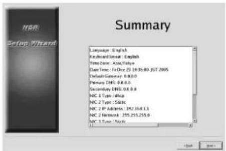
text_image
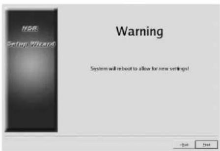
Summary Language: English Keyboard Layout: English Time Zone: Asia/Time Date Time: Fri Dec 23 14:36:00 JST 2005 Default Gateway: 8.8.8.0 Primary DNS: 8.8.8.0 Secondary DNS: 8.8.8.0 NIC 1 Type: dNpc NIC 2 Type: Static NIC 2 IP Address: 192.358.1.1 NIC 2 Network: 255.255.255.0 NIC 3 Type: StaticThe [Warning] screen appears.
13 Click [Finish].
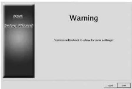
text_image
NSR Setup Wizard Warning System will reboot to allow for new settings!The NSR restarts automatically.
Camera IP Address Configuration and Registration to NSR
After restarting, the logon screen appears. Next, configure the IP addresses for cameras and register them to the NSR.
1 Type your user name and password, and then click [Log on].
Default User Name: admin Default Password: admin
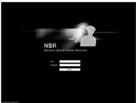
text_image
NSR Network Surveillance Recorder Input Password 10.000The Camera screen appears in the Configuration window.
2 Click [Camera IP Setup].
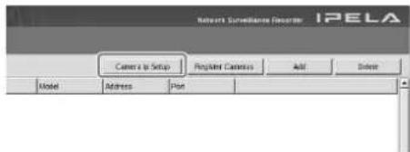
text_image
Network Surveillance Recorder: IPELA Camera to Setup Registered Camera Add Delete Model Address PlanIf the IP addresses for the cameras have already been set, click [Register All] and proceed to Step 5.
The Camera IP Setup window appears.
3 Perform the following settings.
text_image
C:\Users\Program123\Users\Program123\Users\Program123\Users\Program123\Users File Path Settings Name: C:\Users\Program123\Users\Program123\Users\Program123\Users\Program123\Users\Program123\Users Description: Summary: 0.00000000000000000000000000000000000000000000000000000000000000000000000000000000000000000000000 Summary: 1.4.1.1.1.1.1.1.1.1.1.1.1.1.1.1.1.1.1.1.1.1.1.1.1.1.1.1.1.1.1.1.1.1.1.1.1.1.1.1.1.1.1.1.1.1.1.1.1.1.1.1.2 Description: Summary: 2.5.2.2.2.2.2.2.2.2.2.2.2.2.2.2.2.2.2.2.2.2.2.2.2.2.2.2.2.2.2.2.2.2.2.2.2.2 Summary: 3.6.3.3.3.3.3.3.3.3.3.3.3.3.3.3.3.3.3.3.3.3.3.3 Summary: 4.7.4.4.4.4.4.4.4.4.4.4.4.4.4.4.4.4.4. Summary: 5.8.5.5.5.5.5.5.5.5.5.5. Summary: 6.9.6.6.6.6.6.6.6. Summary: 7.1-7 Summary: 7 Summary: 7 Summary: 7 Summary: 7 Summary: 7 Summary: 7 Summary: 7 Summary: 7 Summary: 7 Summary: 7 Summary: 7 Summary: 7 Summary: 7 Summary: 7 Summary: 7 Summary: 7 Summary: 7 Summary: 7 Summary: 7 Summary: 7 Summary: C:\Users\Program123\Users\Program123\Users\Program123\Users\Program123\Users\Program123\Users\Program123\Users\Program123\Users\Program123\Users\Program123\Users\Program123\Users\Program123\Users\Program123\Users\Program123\Users\Program123\Users\Program123\Users Summary: 8 Summary: 9 Summary: 9 Summary: 9 Summary: 9 Summary: 9 Summary: 9 Summary: 9 Summary: 9 Summary: 9 Summary: 9 Summary: 9 Summary: 9 Summary: 9 Summary: 9 Summary: 9 Summary: 9 Summary: 9 Summary: 9 Summary: 9 Summary: 9 Summary: 8 Summary: 8 Summary: 8 Summary: 8 Summary: 8 Summary: 8 Summary: 8 Summary: 8 Summary: 8 Summary: 8 Summary: 8 Summary: 8 Summary: 8 Summary: 8 Summary: 8 Summary: 8 Summary: 8 Summary: 8 Summary: 8 Summary: 8 Summary: 7 Summary: 7 Summary: 7 Summary: 7 Summary: 7 Summary: 7 Summary: 7 Summary: 7 Summary: 7 Summary: 7 Summary: 7 Summary: 7 Summary: 7 Summary: 7 Summary: 7 Summary: 7 Summary: 7 Summary: 7 Summary: 7 Summary: 6 Summary: 6 Summary: 6 Summary: 6 Summary: 6 Summary: 6 Summary: 6 Summary: 6 Summary: 6 Summary: 6 Summary: 6 Summary: 6 Summary: 6 Summary: 6 Summary: 6 Summary: 6 Summary: 6 Summary: 6 Summary: 6 Summary: 6 Summary: 5In the Camera IP Setup window, you can search for cameras on the same network by MAC address and configure their IP addresses all at once.
(1) Select the network to search in the field labeled "1. Select Network Device for IP Setup." Normally, Network 1 is selected as the camera network, and a list of the cameras found appears in the "Found Camera List." The check boxes of all found cameras are selected.
(2) Enter the following information in the field labeled "2. Set Camera network setting."
- The user name and password of the camera you are configuring settings for.
- The range of IP addresses on the same network (default: 0 to 254) for which to perform automatic assignment.
- The http port number (default: 80) for communicating with cameras.
* If there is a fixed range of IP addresses that can be assigned to cameras, make sure to specify the correct range.
(3) Click [Set].
The information you entered is reflected in the "Found Camera List."
IP addresses are assigned within the specified range. Because the list does not expand to compensate if there are not enough IP addresses, make sure the list is set correctly by directly changing addresses in the list as needed. At this stage, the settings have not yet been applied to the camera.
(4) Click [Apply].
This configures the camera settings using the information developed in the list. It takes a few moments for the settings to complete.
4 When the settings for each camera are complete, click [Register All].
The Register Cameras window appears.
5 Perform the following settings.
text_image
Properties List all user types: Normal: If non-protect and update common please add "Register" for "Help" Normal: [ ] Normal [ ] Normal [ ] Normal [ ] Normal [ ] Normal [ ] Normal [ ] Normal [ ] Normal [ ] Normal [ ] Normal [ ] Normal [ ] Normal [ ] Normal [ ] Normal [ ] Normal [ ] Normal [ ] Normal [ ] Normal [ ] Normal [ ] Normal [ ] Normal [ ] Normal [ ] Normal [ ] Normal [ ] Normal [ ] Normal [ ] Normal [ ] Normal [ ] Normal [ ] Normal [ ] Normal [ ] Normal [ ] Normal [ ] Normal[ ] Normal [ ] Normal [ ] Normal [ ] Normal [ ] Normal [ ] Normal [ ] Normal [ ] Normal [ ] Normal [ ] Normal [ ] Normal [ ] Normal [ ] Normal [ ] Normal [ ] Normal [ ] Normal [ ] Normal [ ] Normal [ ] Normal [ ] Normal [ ] Normal [ ] Normal [ ] Normal [ ] Normal [ ] Normal [ ] Normal [ ] Normal [ ] Normal [ ] Normal [ ] Normal [ ] Normal [ ] Normal [ ] Normal [ ] Configuration Context in File (File) Common to the Registered Select all Downloaded A Programs selected Context in File Check and update Context Name, which is also displayed in the Internet Explorer Select all networks and access to Programs Name. Set following details to selected Context Information Status (Default) All Default User Names Restructuring Password OK Remove Cancel/Remove... CancelIn the Register Cameras window, a list of cameras that have not been registered to the NSR appears with the check box for each selected.
(1) Verify the number of cameras selected for registration in the column labeled “Cameras to be registered”, and confirm the user name and password for each camera.
Note
The user name and password for the cameras are not set by default. You can set the user name and password for the selected cameras all at once under "Register selected Cameras for NSR".
(2) Click [Register].
The selected cameras are registered to the NSR. * By clicking [Camera IP Setup], you can also return to the previous Camera IP Setup window.
6 When registration is complete, click [Close].
The Configuration window returns to the Camera screen. The registered cameras are listed.
7 If necessary, configure the individual settings for each camera.
For details about settings, refer to the supplied user's guide.
text_image
BONY IPELA Name: i.p.10000000 System: i.p.10000000 File Edit View Date Format Connect End Date Time Current: 1237-1237 Current: 1237-1237 Current: 1237-1237 Current: 1237-1237 Current: 1237-1237 Current: 1237-1237 Current: 1237-1237 Current: 1237-1237 Current: 1237 1237 Current: 1237 1237 Current: 1237 1237 Current: 1237 1237 Current: 1237 1237 Current: 1237 1237 Current: 1237 1237 Current: 1237 1237 Current: 5645444444444444444444444444444444444444444444444444444444444444444444444444 Current: 1237-1237 Current: 1237-1237 Current: 1237-1237 Current: 1237-1237 Current: 1237-1237 Current: 1237-1237 Current: 1237-1237 Current: 1237 -1237 Current: 1237 -1237 Current: 1237 -1237 Current: 1237 -1237 Current: 1237 -1237 Current: 1237 -1237 Current: 1237 -1237 Current: 1237 -1237 Current: 564544444444444444444444444444444444444444444 Current: 1237-1237 Current: 1237-1237 Current: 1237-1237 Current: 1237-1237 Current: 56454444444444444444 Current: 5655555555555555555555555555555555555555555555555555555555555555555555555555555555 Current: 1237-1237 Current: 1237-1237 Current: 1237-1237 Current: 1237-1237 Current: 1237-1237 Current: 566666666666666666666666666666666666666666666666666666666666666666666666666666666666666666666666668
When you have verified the settings for each camera, click [Monitoring].
The “Monitoring” window appears. By clicking [Configure], you can switch to the “Configuration” screen and make changes to the settings.
text_image
Sony iPela General 100% 100% 100% 100% 100% 100% 100% 100% 100% 100% 100% 100% 100% 100% 100% 100% 100% 100% 100% 100% 100% 100% 100% 100% 100% 100%* For details on how to use the “Monitoring” screen and “Configuration” screen, refer to the User’s Guide (PDF) included on the supplied NSR Series Manual, Tool & Source Codes CD.
Reconstructing Data Volume (Changing RAID Types) (Only the NSR-100/50)
RAID constructions that can be set as data volumes differ depending on the model number within the NSR-100/50.
* RAID is not available for the NSR-25.
| Model Type | Approximate capacity | Redundancy | Default setting | |
| NSR-100 RAID-5 670 GB Yes Yes | ||||
| RAID-1+0 450 GB Yes | ||||
| RAID-0 900 GB None | ||||
| NSR-50 Spanning 430 GB | Partial | Yes | ||
| RAID-1 210 GB Yes | ||||
Caution
- Be aware that all setting information and recorded images are deleted when reconstructing data volume.
- When changing the settings is necessary, make sure to change the RAID construction beforehand.
1
Connect the USB keyboard and USB mouse to the NSR, and turn on the power. The following screen and a progress bar for hardware startup appear.

text_image
IPELA2
Press F12 on the keyboard while the progress bar is displayed.
The screen similar to the following appears. Example: For the NSR-50 (there are 3 menu items for the NSR-100)
* The number of devices and their names may differ from the following example screen.
| Boot Menu |
| 1.QSI DVD+/-RW SDW-08262.WDC WD2500JD-22HBC0-(S1)3.WDC WD2500JD-22HBC0-(S2)4.PQI IDE DiskOnModule-(SM)<Enter Setup> |
3 Use the arrow keys on the keyboard to select [IDE DiskOnModule], and press Enter. Startup from DiskOnModule (DOM) begins.
text_image
NSR Network Surveillance RecorderAfter startup, the DOM menu appears.
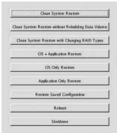
4 Click the third item from the top, [Clean System Restore with Changing RAID Types].
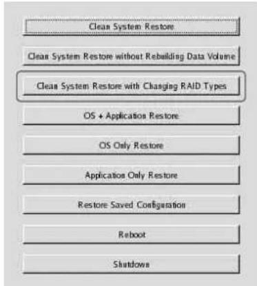
text_image
Clean System Restore Clean System Restore without Rebuilding Data Volume Clean System Restore with Charging RAID Types OS + Application Restore OS Only Restore Application Only Restore Restore Saved Configuration Reboot ShutdownThe RAID Type selection screen appears.
5 Select the RAID Type, and click [OK]. Example: For the NSR-50
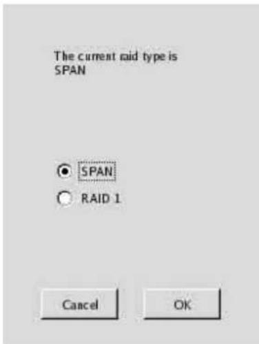
text_image
The current raid type is SPAN ○ SPAN ○ RAID 1 Cancel OKThe confirmation screen appears.
6 Click [OK]. RAID reconstruction for data volume and full system restoration begins. This process can take up to about 5 hours. A progress bar appears during the process. When the process successfully completes, a notification screen appears. Example: For an NSR-50 with RAID 1 selected
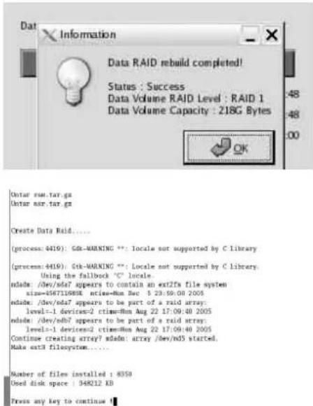
text_image
Data RAID rebuild completed! Status : Success Data Volume RAID Level : RAID 1 Data Volume Capacity : 218G Bytes Enter run.tar.gz Enter run.tar.gz Create Data Raid..... (process: 4419): GIR-WARNING **: Locale not supported by C library (process: 4419): Stk-WARNING **: Locale not supported by C library. Using the fallback 'C' locale. ndade: /dev/nda7 appears to contain an ext2fs file system size=456711688K active=Run Buc 5 23:59:00 2005 ndade: /dev/nda7 appears to be part of a raid array: level=1 devices=2 ctimes=8m Aug 22 17:09:40 2005 ndade: /dev/ndb7 appears to be part of a raid array: levels=1 devices=2 ctimes=8m Aug 22 17:09:40 2005 Continue creating array7 ndedn: array /dev/nd5 started. Make ext3 filesystem....... Number of files installed : 8350 Used disk space : 348212 KB Press any key to continue7 Press Enter after the process completes and the message [Press any key to continue!] appears. The screen returns to the DOM menu.
8 Click [Reboot]. The NSR reboots, and the Setup Wizard appears.
STATUS LED
When an error occurs, the STATUS and ERROR LED light or flash.
1 2 3 4 ERRORSTATUS
The STATUS LED indicates the following error situations.
Error codes displayed during boot stage (The ERROR LED blinks when an error occurs during boot.)
| Error code | STATUS LED | ERROR LED | Possible Cause |
| 1 Blinking234 | Volgepowersupply failure | ||
| 2 BlinkingCPU4an | failure | ||
| 3 Blinking2Defective | memory module | ||
| 4 Blinking2C34S | battery failure | ||
| 5 Blinking234 | Video random access memory (RAM) or controller failure | ||
| 6 Blinking2Harddisk | controller | failure | |
| 7 Blinking2Nohotable | device found | ||
| 8 Blinking234 | No bootable Operating System found | ||
| 9 Blinking234 | One or more hard disk failure | ||
| A Blinking2R34OS | volume failure | ||
| B Blinking234 | Failure to start the X11 server | ||
| C Blinking234 | Failure to start the application | ||
| D Blinking2Reserved | for future use | ||
| E | 1234 | Blinking Reserved for future use | |
| F | 1234 | Blinking RAID data volume failure |
Error codes displayed during operation stage (The ERROR LED lights when an error occurs during operation.)
| Error code | STATUS LED | ERROR LED | Possible Cause |
| 1 On |  | temperature | |
| 2 |  | On | CPU fan failure |
| 3 On |  | supply fan failure | |
| 4 |  | On | Voltage power supply failure |
| 5 On |  | disk drive fan 1 failure | |
| 6 On |  | disk drive fan 2 failure | |
| 7 On |  | disk drive is damaged. | |
| 8 On |  | rved for future use | |
| 9 On |  | rved for future use | |
| A On |  | rved for future use | |
| B On |  | rved for future use | |
| C |  | On | Application functioning failure |
| D On |  | rved for future use | |
| E |  | On | RAID data volume failure |
| F |  | On | Resync operation in RAID data volume* |
* A degradation in system performance will occur when a read error occurs while the resync operation is in progress.
Miscellaneous
LICENSE AGREEMENT
The following “SOFTWARE LICENSE AGREEMENT” applies to the Program provided by Sony.
Please read the following “SOFTWARE LICENSE AGREEMENT” before using Network Surveillance Recorder (Model Name: NSR-100/50/25) (hereinafter referred to as the “Product”).
By using the Product, you agree to the “SOFTWARE LICENSE AGREEMENT”.
Please be aware that the software used in the Product includes a part of software under the different terms and conditions from the following SOFTWARE LICENSE AGREEMENT. You can confirm such software at bundled CD media (hereinafter referred to as “Exceptional Software”). The following “SOFTWARE LICENSE AGREEMENT” does not apply to such Exceptional Software and the respective terms and conditions apply to each Exceptional Software separately from this “SOFTWARE LICENSE AGREEMENT”. Exceptional Software shall never be construed as Program defined in the following SOFTWARE LICENSE AGREEMENT.
SOFTWARE LICENSE AGREEMENT
This is a legal agreement between you (hereinafter referred to as the “User”) and Sony Corporation (hereinafter referred to as “Sony”) pertaining to the right to use the software program (hereinafter referred to as the “Program”). Using the Program indicates User’s acceptance of these terms and conclusion of this Agreement between the User and Sony.
- Copyright and all other rights relating to the Program and documents accompanying the Program are owned by Sony or the original rightful person or organization (hereinafter referred to as the “Original Rightful Person”) granting Sony the right to use the Program. The User is granted no rights other than those specified in this Agreement.
- Sony grants the User the non-exclusive, indivisible and non-transferable right to use the Program for the purpose of using the Product for which the Program designates (hereinafter referred to as the “Right of Use”).
-
The User may not transfer the Right of Use to any third party nor allow for any third party to use the Program unless the User obtains the advance written permission of Sony.
-
The User may not export or transport the Program or documents accompanying the Program from the country where the User purchased the Product to any other country.
- The User may not (i) update, add to, or modify nor (ii) de-assemble or de-compile the Program either in whole or in part without Sony's prior consent.
- THE PROGRAM IS PROVIDED "AS IS" WITHOUT EXPRESS OR IMPLIED WARRANTIES, INCLUDING WARRANTIES OF MERCHANTABILITY AND FITNESS FOR A PARTICULAR PURPOSE OR NON-DEFECTIVENESS.
- If any dispute relating to infringement of copyright, patent, or other intangible property rights arises between the User and a third party as a consequence of use of the Program, the User shall settle the dispute at the User's own expense, and shall make no claim against Sony or the Original Rightful Person.
- Sony may terminate User's license upon notice for failure to comply with any of these terms of this Agreement. Any such termination shall not affect any payments and any compensation for damage. Upon termination, User must immediately destroy the Program together with all copies in any form.
- If the User is a governmental entity, the use, duplication or disclosure of the Program and accompanying documentation by the User are subject to the restrictions set forth in subparagraphs (c)(1) and (c)(2) of the Commercial Computer Software clause at FAR 52.227-19, and subparagraph (c)(I)(ii) of the Rights in Technical Data and Computer Software clause at DOD FAR 252.227-7013 and any comparable federal, state or local law or regulation and, for this purpose, the manufacturer is Sony Corporation located at 1-7-1 Konan, Minato-ku, Tokyo, Japan.
Concerning GPL-LPGL
This product includes GPL/LGPL-compliant software. You may acquire the source code for this software, as well as modify and distribute it.
The source code is included on the supplied “NSR Series Manual, Tool & Source Codes CD”. Do not direct questions to Sony regarding the contents of the source code.
Some software provided with this product uses the glibc and gtk2 developmental LGPL libraries with a method called dynamic linking (also, refer to the “User’s Guide” (PDF) on the supplied “NSR Series Manual, Tool & Source Codes CD”). As regulated by LGPL, the source code for these pieces of software is not provided.
However, when limited to the software owner, analysis of the object code for the purpose of personal revisions or debugging is permitted.
MPEG-4 Video Patent Portfolio License
THIS PRODUCT IS LICENSED UNDER THE MPEG-4 VISUAL PATENT PORTFOLIO LICENSE FOR THE PERSONAL AND NON-COMMERCIAL USE OF A CONSUMER FOR
(i) ENCODING VIDEO IN COMPLIANCE WITH THE MPEG-4 VISUAL STANDARD ("MPEG-4 VIDEO")
AND/OR
(ii) DECODING MPEG-4 VIDEO THAT WAS ENCODED BY A CONSUMER ENGAGED IN A PERSONAL AND NON-COMMERCIAL ACTIVITY AND/OR WAS OBTAINED FROM A VIDEO PROVIDER LICENSED BY MPEG LA TO PROVIDE MPEG-4 VIDEO.
NO LICENSE IS GRANTED OR SHALL BE IMPLIED FOR ANY OTHER USE. ADDITIONAL INFORMATION INCLUDING THAT RELATING TO PROMOTIONAL, INTERNAL AND COMMERCIAL USES AND LICENSING MAY BE OBTAINED FROM MPEG LA, LLC. SEE HTTP://WWW.MPEGLA.COM
Troubleshooting
Before contacting your retailer or a Sony Support Center, please check the following items. If the problem persists, contact them.
The NSR does not work.
- Verify that the power switch is turned on.
- Verify that the power cable is connected correctly.
- Make sure the wall outlet has power. Test it by plugging another device.
- Verify that the hard disk drives are not being accessed (the HDD LEDs on the front of the recorder do not blink), and then turn it off forcibly by pressing and holding the power switch at the rear of the unit for approximately 10 seconds. Restart the NSR.
- During the startup procedure, the NSR checks the file system. The length of this check varies depending on the amount of data on the NSR (in some extreme case, it can take as long as two hours). During the file system check, the HDD LEDs on the front of the recorder blink.
- If the NSR does not start correctly, the following screen may appear.
Example: For the NSR-100/50
text_image
Clean System Restore Clean System Restore without Rebuilding Data Volume Clean System Restore with Changing RAID Types OS + Application Restore OS Only Restore Application Only Restore Restore Saved Configuration Reboot ShutdownsWhen it does, proceed as follows.
1 Click [Shutdown] and turn off the NSR.
2 Referring to "Cannot access the hard drive.", verify whether the NSR hard disks are correctly connected.
3 Restart the NSR and verify whether it starts.
4 If the same screen as above appears again, insert the supplied NSR Series Recovery CD into the CD and DVD drive, and then turn off the NSR. In this state, restart the NSR, and select "2. Check file System" when the following screen appears.
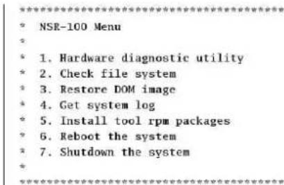
text_image
NSR-100 Menu * 1. Hardware diagnostic utility * 2. Check file system * 3. Restore DOM image * 4. Get system log * 5. Install tool rpm packages * 6. Reboot the system * 7. Shutdown the systemEnter your choice:
Checking the file system may take several hours.
5 When the check is finished, select "7. Shutdown the system", and turn off the recorder. In addition, do not use any menu option other than "2. Check file system" or "7. Shutdown the system", as the others are for maintenance purposes.
6 Restart the NSR and immediately eject the NSR Series Recovery CD. Then verify whether the NSR starts correctly.
The monitor remains blank.
- Verify whether the NSR is on.
- Verify whether the power cord is correctly connected.
- Verify whether the monitor cable is correctly connected. Confirm that the monitor is connected to monitor connector 1.
- If you configure the wrong monitor resolution, the “Out of range” message may appear when the monitor resolution is too low compared to the monitor output. Press CTRL+ALT+MINUS SIGN as many times as necessary to lower the resolution of the output video. When the output image resolution reaches the resolution of the monitor, the image appears. Subsequently, reconfigure your monitor resolution. For details, refer to the “User’s Guide” (PDF) on the supplied “NSR Series Manual, Tool & Source Codes CD”.
The new external hardware is not working properly.
- Make sure the cables for the new external device are firmly connected and the pins are not bent.
An external device connected to a USB connector does not work.
- Reduce the number of external devices connected to USB ports.
- Refer to the documentation that came with the device.
System cannot read the DVD/CD information.
- Make sure that you are using the correct type of disc.
- Make sure the DVD/CD is properly inserted in the drive.
- Check if the DVD/CD is clean and not scratched.
The DVD/CD tray cannot be ejected.
- Make sure that the NSR is turned on.
- Slowly insert the tip of a pen or paperclip into the eject hole on the DVD/CD drive. Pull the tray out from the drive then remove the disc.
The NETWORK LED does not light up.
- Check the cabling and network equipment for the proper connection.
Cannot access the hard disk drive.
- Make sure the hard drive is properly inserted.
- Check the HDD LEDs on the front panel of the system. Identify the defective hard disk drive by reading the drive LEDs. A defective HDD LED does not light up.
- Due to rapid flashing during frequent access to the hard disk drive, the HDD LED may appear unlit in bright environments.
Cannot access the CompactFlash card. (Only the NSR-100/50)
- Make sure the CompactFlash card is properly inserted.
- Make sure the CompactFlash card is formatted as VFAT file system.
- Make sure the CompactFlash card is not removed within 10 seconds after accessing the card. If you remove the card while files are being accessed or transferred, the NSR may become unstable. You must restart the system in order to access the CompactFlash card.
Cannot access NSR from a remote client.
- Make sure the NSR is operating properly (there should be no abnormalities with the hard disk drive, network, software or other items).
- Make sure the correct user name, password, and connection port are set in RealShot Manager.
- Refer to the troubleshooting section of the user's guide for the RealShot Manager.
The NSR heats up quickly
- Make sure that nothing is blocking the ventilation openings on the front, sides, and rear of the unit and dust has not accumulated in them.
I/O Port
Pin Assignment of I/O Port
Sensor In
| Pin NO. | SENSOR IN | ||||
| 1 | 3 | . | 3 | v | |
| 2 | I | N | - | 8 | - |
| 3 | I | N | - | 8 | + |
| 4 | I | N | - | 7 | - |
| 5 | I | N | - | 7 | + |
| 6 | I | N | - | 6 | - |
| 7 | I | N | - | 6 | + |
| 8 | I | N | - | 5 | - |
| 9 | I | N | - | 5 | + |
| 10 IN_ | 4 - | ||||
| 11 IN_ | 4 + | ||||
| 12 IN_ | 3 - | ||||
| 13 IN_ | 3 + | ||||
| 14 IN_ | 2 - | ||||
| 15 IN_ | 2 + | ||||
| 16 IN_ | 1 - | ||||
| 17 IN_ | 1 + | ||||
| 18 GND | |||||
Alarm Out
| Pin NO. | ALARM OUT |
| 1 GND | |
| 2 OUT_8 - | |
| 3 OUT_8 + | |
| 4 OUT_7 - | |
| 5 OUT_7 + | |
| 6 OUT_6 - | |
| 7 OUT_6 + | |
| 8 OUT_5 - | |
| 9 OUT_5 + | |
| 10 OUT_4 - | |
| 11 OUT_4 + | |
| 12 OUT_3 - | |
| 13 OUT_3 + | |
| 14 OUT_2 - | |
| 15 OUT_2 + | |
| 16 OUT_1 - | |
| 17 OUT_1 + | |
| 18 3.3 v | |
Using the I/O Receptacle
Insert a small slotted screwdriver into the upper or lower slot of the hole you want to connect a wire to (AWG No. 28 to 18). Hold down the screwdriver and insert the wire, then release the screwdriver.
Caution
Do not use excessive force when inserting the screwdriver into the slot. Doing so may result in damage.
①
②
③
Repeat this procedure to connect all required wires.
Wiring Diagram 1 for Sensor Input
Inside of this unit Outside
3, 5, 7, 9, 11, 13, 15, 17pin
(SENSOR IN+)
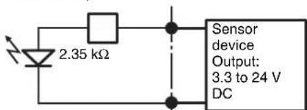
text_image
2.35 kΩ Sensor device Output: 3.3 to 24 V DC2, 4, 6, 8, 10, 12, 14, 16pin
(SENSOR IN-)
Wiring Diagram 2 for Sensor Input
Inside of this unit Outside
1 pin (VDD) (200 mA max)
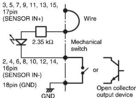
text_image
3, 5, 7, 9, 11, 13, 15, 17pin (SENSOR IN+) 2.35 kΩ Wire Mechanical switch 2, 4, 6, 8, 10, 12, 14, 16pin (SENSOR IN-) 18pin (GND) GND or Open collector output deviceNote
When the wiring diagram 2 is used, the NSR is not electrically isolated, so be sure to construct external circuits that will not produce noise, excess voltage, or overcurrents.
Wiring Diagram for Alarm Output
Inside of this unit Outside
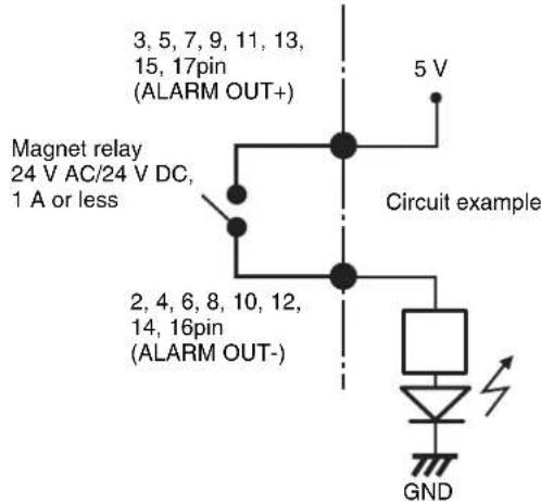
text_image
3, 5, 7, 9, 11, 13, 15, 17pin (ALARM OUT+) Magnet relay 24 V AC/24 V DC, 1 A or less 2, 4, 6, 8, 10, 12, 14, 16pin (ALARM OUT-) 5 V Circuit example GND安全のために
©2006 Sony Corporation
商標について
natural_image
Technical line drawing of a mechanical rail or beam assembly with mounting holes and directional arrows indicating motion (no text or symbols)text_image
Technical diagram showing a ruler measuring a length with an arrow indicating measurement directionnatural_image
Diagram of a computer drive rear panel with connectors and ports, showing cable connection (no text or labels)natural_image
Line drawing of a computer tower rear panel with connectors and ventilation slots (no text or symbols)電源コードを接続する
1 付属の電源コードを接続する。
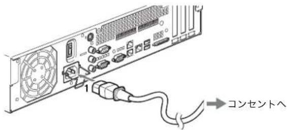
text_image
1 コンセントへnatural_image
Diagram showing a fan connected to an VGA socket with a cable, no text or symbols presentご注意
text_image
Diagram of computer RAM slots and connectors with labeled components including CPU socket, GPIO, and Ethernet portsメモ
natural_image
Diagram of computer hardware rear panel showing fan, socket, connectors, and drive components (no text or labels)text_image
Select Language Chinese-Simplified English French German Italian Japanese Spanish「EULA」画面が表示されます。
text_image
NSR Setup Wizard EULA The following "SOFTWARE LICENSE AGREEMENT" applies to the Program provided by Sony. Please read the following "SOFTWARE LICENSE AGREEMENT" before using Network Surveillance Recorder (Model Name: NSR-50/100) (hereinafter referred to as the "Product"). By using the Product, you agree to the "SOFTWARE LICENSE AGREEMENT". ^ Accept ^ Declinetext_image
NSA Setup Wizard Keyboard Layout Chinese-Simplified English French German Italian Japanese Spanishtext_image
Date and Time Year Month Day 2005 12 13 Hour Minute 10 40 AM/FM C AM & PMtext_image
General Network Setting Primary DNS 0 0 0 0 Secondary DNS 0 0 0 0 Default Gateway 0 0 0 0Primary DNS
text_image
Monitor #1 Model Generic Monitor Dual Head Generic LCD Display: LCD Panel 100x1268.0 x 31.5 Generic CRT Display: Monitor 1024x768.0 x 33.5 x 57.0 Generic CRT Display: Monitor 1024x768.0 x 33.5 x 57.0 Others Power, Audio, Smart, APW733B, 31.0 x 34.0 x 35.0 x 33.0 Power, Audio SS, APW733B, 36.0 x 36.0 x 36.0 x 34.0 Power, Audio PC, APW733B, 38.0 x 38.0 x 39.0 x 37.0 Power, Audio DC, APW733B, 38.0 x 38.0 x 39.0 x 37.0 Power, Audio ST, APW733B, 38.0 x 38.0 x 39.0 x 37.0 Resolution: 1024x768メモ
text_image
Host Name Host Name: NSR100_5048 Domain Name: localdomainHost Name
本機のホスト名を入力します。
メモ
text_image
Summary Language: English Keyboard layer: English Time Zone: Asia/Time Date Time: Fri Dec 23 14:36:00 JST 2005 Default Gateway: 0.0.0.0 Primary DNS: 0.0.0.0 Secondary DNS: 0.0.0.0 NIC 1 Type: dhcp NIC 2 Type: Static NIC 2 IP Address: 192.368.1.1 NIC 2 Network: 255.255.255.0 NIC 3 Type: Static「Warning」画面が表示されます。
13 [終了] をクリックする。
text_image
NSR Setup Wizard Warning System will reboot to allow for new settings!text_image
Network Surveillance Recorder IPELA Camera to Setup Register Camera Add Delete Model Address Porttext_image
Access Provider 1. Select Provider for IP Path IP Path: 000000000000000000000000000000000000000000000000000000000000000000000000000000000000000000000000000 File Region: IP Path Name: IP Path Address: IP Path Location: IP Path Address: IP Path Address: IP Path Address: IP Path Address: IP Path Address: IP Path Address: IP Path Address: IP Path Address: IP Path Address: IP Path Address: IP Path Address: IP Path Address: IP Path Address: IP Path Address: IP Path Address: IP Path Address: IP Path Address: IP Path Address: IP Path Address: IP Path Address: IP Path Access Provider: IP Path Access Provider: IP Path Access Provider: IP Path Access Provider: IP Path Access Provider: IP Path Access Provider: IP Path Access Provider: IP Path Access Provider: IP Path Access Provider: IP Path Access Provider: IP Path Access Provider: IP Path Access Provider: IP Path Access Provider: IP Path Access Provider: IP Path Access Provider: IP Path Access Provider: IP Path Access Provider: IP Pathtext_image
List of items List of categories: List of items (e.g. 'Item' or 'Number') List of items (e.g. 'Number') List of items (e.g. 'Number') List of items (e.g. 'Number') List of items (e.g. 'Number') List of items (e.g. 'Number') List of items (e.g. 'Number') List of items (e.g. 'Number') List of items (e.g. 'Number') List of items (e.g. 'Number') List of items (e.g. 'Item' or 'Number') List of items (e.g. 'Number') List of items (e.g. 'Number') List of items (e.g. 'Number') List of items (e.g. 'Number') List of items (e.g. 'Number') List of items (e.g. 'Number') List of items (e.g. 'Number') Select to list of items Select to list of items Select to list of items Select to list of items Select to list of items Select to list of items Select to list of items Select to list of items Select to list of items Select to list of items Select to list of items Select to list of items Select to list of items Select to list of items Select to list of items Next step Next steptext_image
Clean System Restore Clean System Restore without Rebuilding Data Volume Clean System Restore with Changing RAID Types OS + Application Restore OS Only Restore Application Only Restore Restore Saved Configuration Reboot Shutdowntext_image
The current raid type is SPAN ○ SPAN ○ RAID 1 Cancel OK確認画面が表示されます。
text_image
Data RAID rebuild completed! Status : Success Data Volume RAID Level : RAID 1 Data Volume Capacity : 218G Bytes Enter run.tar.gz Enter nor.tar.gz Create Data Raid..... (process: 4419): Gtk-WARNING ***; locale not supported by C library (process: 4419): Gtk-WARNING ***; Locale not supported by C library. Using the fallback 'C' locale. ndads: /dev/sda7 appears to contain an ext2fs file system time=4587136800; time=Num Dev $ 23:59:00 2005 ndads: /dev/sda7 appears to be part of a raid array: level=1 devices=2 rtime=Num Aug 22 17:09:40 2005 ndads: /dev/sda7 appears to be part of a raid array: levels=1 devices=2 rtime=Num Aug 22 17:09:40 2005 Continue creating array? ndads: array /dev/nd5 started. Make ext3 filesystem....... Number of files installed : 8350 Used disk space : 348212 KB Press any key to continue !text_image
Clean System Restore Clean System Restore without Rebuilding Data Volume Clean System Restore with Changing RAID Types OS + Application Restore OS Only Restore Application Only Restore Restore Saved Configuration Reboot Shutdownstext_image
NSR-100 Menu * 1. Hardware diagnostic utility * 2. Check file system * 3. Restore DOM image * 4. Get system log * 5. Install tool rpm packages * 6. Reboot the system * 7. Shutdown the system * Enter your choice:| Pin NO. | SENSOR IN | ||||
| 1 | 3 | , | 3 | v | |
| 2 | I | N | - | 8 | - |
| 3 | I | N | - | 8 | + |
| 4 | I | N | - | 7 | - |
| 5 | I | N | - | 7 | + |
| 6 | I | N | - | 6 | - |
| 7 | I | N | - | 6 | + |
| 8 | I | N | - | 5 | - |
| 9 | I | N | - | 5 | + |
| 10 IN_4 - | |||||
| 11 IN_4 + | |||||
| 12 IN_3 - | |||||
| 13 IN_3 + | |||||
| 14 IN_2 - | |||||
| 15 IN_2 + | |||||
| 16 IN_1 - | |||||
| 17 IN_1 + | |||||
| 18 GND | |||||
アラーム出力
| Pin NO. ALARM OUT | ||||||
| 1 | GND | |||||
| 2 | O | U | T | _ | 8 | - |
| 3 | O | U | T | _ | 8 | + |
| 4 | O | U | T | _ | 7 | - |
| 5 | O | U | T | _ | 7 | + |
| 6 | O | U | T | _ | 6 | - |
| 7 | O | U | T | _ | 6 | + |
| 8 | O | U | T | _ | 5 | - |
| 9 | O | U | T | _ | 5 | + |
| 10 OUT_4 - | ||||||
| 11 OUT_4 + | ||||||
| 12 OUT_3 - | ||||||
| 13 OUT_3 + | ||||||
| 14 OUT_2 - | ||||||
| 15 OUT_2 + | ||||||
| 16 OUT_1 - | ||||||
| 17 OUT_1 + | ||||||
| 18 3.3 v | ||||||
I/O ポートの接続方法
(NSR-100/50 uniquement) 80
Diodes ÉTAT 81
Divers 82
ACCORD DE LICENCE 82
A propos de GPL-LPGL 83
Licence MPEG-4 Video Patent Portfolio ..... 83
©2006 Sony Corporation
Marques de fabrique
natural_image
Technical line drawing of a mechanical rail or conveyor system with directional arrows indicating motion (no text or symbols)text_image
Technical diagram showing a ruler with measurement markings and an arrow indicating direction, likely for engineering or technical purposes.natural_image
Diagram of a computer drive rear panel with connectors and ports, showing cable connection (no text or labels)natural_image
Line drawing of an internal computer drive bay with connectors and ventilation slots (no text or symbols)Remarque
natural_image
Technical line drawing showing a fan connected to an VGA socket and cable (no text or symbols present)Remarque
text_image
Diagram of computer RAM slots and connectors with labeled ports and connectorsRemarque
natural_image
Diagram of computer hardware rear panel showing front panel, connectors, and drive slots (no text or labels)text_image
Select Language Chinese Simplified English French German Italian Japanese Spanishtext_image
NSR Setup Wizard EULA The following "SOFTWARE LICENSE AGREEMENT" applies to the Program provided by Sony. Please read the following "SOFTWARE LICENSE AGREEMENT" before using Network Surveillance Recorder (Model Name: NSR-50/100) (hereinafter referred to as the "Product"). By using the Product, you agree to the "SOFTWARE LICENSE AGREEMENT". Accept > Decline OK Nexttext_image
NSH Setup Wizard Keyboard Layout Chinese-Simplified English French German Italian Japanese Spanishtext_image
General Network Setting Primary DNS 0 0 0 0 Secondary DNS 0 0 0 0 Default Gateway 0 0 0 0Primary DNS
LAN2: Clients distants
text_image
Monitor #1 Model F Generic Monitor Dual Head Generic LCD Display: LCD Panel 300x1209.0.115 Generic CRT Display: Monitor 10/4x768.0.315.57 Dual Head F Others New Audio SL: APWSTX, J14.0 SEA SEB 110.0 New Audio SL: APWSTX, J0.0 SEA SEB 08.0 New Audio SL: APWSTX, J0.0 SEA SEB 130.0 New Audio SL: APWSTX, J0.0 SEA SEB 012.0 New Audio SL: APWSTX, J0.0 SEA SEB 130.0 Resolution 1024x768Remarques
text_image
Host Name Host Name: NSR100_5048 Domain Name: localdomainHost Name
text_image
Summary Language: English Keyboard Level: English Time/Time: Asia/Telaya Date Time: 14 Dec 23 14:30:09 JST 2005 Default Gateway: 0.0.0.0 Primary DNS: 0.0.0.0 Secondary DNS: 0.0.0.0 NC 1 Type: Debug NC 2 Type: Static NC 2 IP Address: 192.368.1.1 NC 2 Network: 255.255.255.0 NC 3 Type: Statictext_image
NSR Setup Wizard Warning System will reboot to allow for new settings!text_image
Network Surveillance Recorder IPELA Camera to Setup Register Camera Add Delete Model Address Poortext_image
File Edit Options File Edit Options to File Name: Name Name Address: Address List of Fixed Content View From Here to Web, Forward About Web, Select About Web Check For Preset: Web Address: Next Page (Enter) Export: New Page (New) Export: New Page Description: Format Controls Reported Controls Unadjusted Controls Sales of Sales of Web 1. Continuous settings To be found in the following settings by the first few categories can be further add to Include any details to selected categories. □ Advanced settings □ Remove and Use Files □ Remove and Use Posters □ or above □ To include total PDF tables in each category according to selected categories. Range of PDF tables: 600,000, 1, 2 50,000, 1, 200 □ Sub-tract and group, and use the same PDF tables as follows: □ To select categories with PDF tables: 48, 60 (2000-2003) Add Apply settings to selected categories: □ Create Cines: Cines and Settings: Cines to specific categories: Regulate controls Closetext_image
System Set of System Parameters Show it to set the following parameters: where any "Program" is selected. Select [Form1] [Form2] [Form3] [Form4] [Form5] [Form6] [Form7] [Form8] [Form9] [Form10] Settings System or settings URL Settings is not registered Delete it Details List A. Program installed: Document-1 (B) C. Check and update Current Status, Implementation Status and Settings D. Use C#e as an event that "Program" has been E. Set Existing Status in Selected Documents Information Received: All Location Use Name: No Information on Name? OK Apply Cancel On Stop Cleartext_image
Clean System Restore Clean System Restore without Rebuilding Data Volume Clean System Restore with Changing RAID Types OS + Application Restore OS Only Restore Application Only Restore Restore Saved Configuration Reboot Shutdowntext_image
The current raid type is SPAN ○ SPAN ○ RAID 1 Cancel OKtext_image
Ontar run.tar.gz Ontar run.tar.gz Create Data Raid..... (process: 4419): GB-WARNING **; locale not supported by C Library (process: 4419): Gtk-WARNING **; Locale not supported by C Library. Using the fallback 'C' locale. mdads: /dev/sda7 appears to contain an ext2fx file system size=456713688 mtise-Mon Dec 5 23:50:00 2005 mdads: /dev/sda7 appears to be part of a raid array: level=1 devices=2 mtise-Mon Aug 22 17:00:48 2005 mdads: /dev/edb7 appears to be part of a raid array: level=1 devices=2 mtise-Mon Aug 22 17:00:48 2005 Continue creating array? adads: array /dev/wd5 started. Make ext3 filesystem..... Number of files installed : 8350 Used disk space : 348212 KB Press any key to continuetext_image
Clean System Restore Clean System Restore without Rebuilding Data Volume Clean System Restore with Changing RAID Types OS + Application Restore OS Only Restore Application Only Restore Restore Saved Configuration Reboot Shutdowntext_image
NSR-100 Menu * 1. Hardware diagnostic utility * 2. Check file system * 3. Restore DOM image * 4. Get system log * 5. Install tool rpm packages * 6. Reboot the system * 7. Shutdown the systemEnter your choice:
| Contact No. | ENTREE CAPTEUR | ||||
| 1 3.3 v | |||||
| 2 | I | N | - | 8 | - |
| 3 | I | N | - | 8 | + |
| 4 | I | N | - | 7 | - |
| 5 | I | N | - | 7 | + |
| 6 | I | N | - | 6 | - |
| 7 | I | N | - | 6 | + |
| 8 | I | N | - | 5 | - |
| 9 | I | N | - | 5 | + |
| 10 IN_4 - | |||||
| 11 IN_4 + | |||||
| 12 IN_3 - | |||||
| 13 IN_3 + | |||||
| 14 IN_2 - | |||||
| 15 IN_2 + | |||||
| 16 IN_1 - | |||||
| 17 IN_1 + | |||||
| 18 GND | |||||
Sortie d'alarme
| Contact No. Sortie d'alarme | |||||
| 1 | GND | ||||
| 2 | O | U | T | - | 8 |
| 3 | O | U | T | - | 8 |
| 4 | O | U | T | - | 7 |
| 5 | O | U | T | - | 7 |
| 6 | O | U | T | - | 6 |
| 7 | O | U | T | - | 6 |
| 8 | O | U | T | - | 5 |
| 9 | O | U | T | - | 5 |
| 10 OUT_4 - | |||||
| 11 OUT_4 + | |||||
| 12 OUT_3 - | |||||
| 13 OUT_3 + | |||||
| 14 OUT_2 - | |||||
| 15 OUT_2 + | |||||
| 16 OUT_1 - | |||||
| 17 OUT_1 + | |||||
| 18 3.3 v | |||||
contact 3, 5, 7, 9, 11, 13, 15, 17
(ENTREE CAPTEUR+)
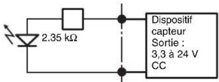
contact 2, 4, 6, 8, 10, 12, 14, 16
(ENTREE CAPTEUR-)
1 contact (VDD) (200 mA max)

© 2006 Sony Corporation
Warenzeichen
natural_image
Technical line drawing of a mechanical rail or conveyor system with directional arrows indicating motion (no text or symbols)natural_image
Technical line drawing of a mechanical assembly with no visible text or symbolsnatural_image
Line drawing of a computer drive rear panel with connectors and ventilation fan (no text or symbols)natural_image
Line drawing of a computer tower rear panel with connectors and ventilation slots (no text or symbols)Hinweis
natural_image
Technical line drawing showing a fan connected to an VGA socket and cable (no text or symbols present)Hinweis
text_image
Diagram of an electronic device rear panel with labeled ports and connectors, showing internal components like USB drive, port, and connector pins.Hinweis
natural_image
Front panel view of a computer drive showing fan, socket, connectors, and grid layout (no text or symbols)text_image
NSR Setup Wizard Chinese Simplified English French German Italian Japanese Spanishtext_image
EULA The following "SOFTWARE LICENSE AGREEMENT" applies to the Program provided by Sony. Please read the following "SOFTWARE LICENSE AGREEMENT" before using Network Surveillance Recorder (Model Name: NSR-50/100) (hereinafter referred to as the "Product"). By using the Product, you agree to the "SOFTWARE LICENSE AGREEMENT". Accept > Declinetext_image
NSR Setup Wizard Keyboard Layout Chinese Simplified English French German Italian Japanese Spanishtext_image
Date and Time Year Month Day 2005 12 13 Hour Minute 10 40 AM/FM AM × PM Start Backtext_image
General Network Setting Primary DNS 0 0 0 0 Secondary DNS: 0 0 0 0 Default Gateway: 0 0 0 0Primary DNS
IP Address: 192.168.[0/1/2]*.1
Netmask: 255.255.255.0
text_image
Monitor #1 Model F Generic Monitor □ Dual Head Generic LCD Display: LCD Panel 340x100X 0.315 Generic CRT Display: Monitor 10/24x764, 0.315-571 Generic CRT Display: Monitor 1200x800, 0.315-571 F Others Basic Area 54% APW135, 21.9 x 54.0 x 58.0 x 11.0 Area Area 54% APW135, 30.0 x 56.0 x 58.0 x 0.0 Area Area 54% APW135, 30.0 x 54.0, 58.0 x 11.0 Area Area 54% APW135, 30.0 x 64.0 x 76.0 x 11.0 Area Area 54% APW135, 30.0 x 78.0 x 58.0 x 11.0 Resolution 1024x768Hinweise
text_image
Host Name Host Name: NSR100_5048 Domain Name: localdomainHost Name
text_image
Summary Language: English Keyboard layer: English TimeZone: Asia/Time DateTime: Fri Dec 23 14:36:09_JST 2005 Default Gateway: 8.0.0.0 Primary DNS: 8.0.0.0 Secondary DNS: 0.0.0.0 NC 1 Type: .disc NC 2 Type: Static NC 2 IP Address: 192.316.1.1 NC 2 Network: 255.255.255.0 NC 3 Type: Statictext_image
MSB Setup Wizard Warning System will reboot to allow for new settings!text_image
NSR Network Surveillance Recorder Type: Reported: © 2006 Asia Securitiestext_image
Network Surveillance Decoder IPELA Connect In Setup Regulate Camera Add Delete Model Address Porttext_image
Options Models List of Options Models: Name: [1] Name: [2] Name: [3] Name: [4] Name: [5] Name: [6] Name: [7] Name: [8] Name: [9] Name: [10] Name: [11] Name: [12] Name: [13] Name: [14] Name: [15] Name: [16] Name: [17] Name: [18] Name: [19] Name: [20] Name: [21] Name: [22] Name: [23] Name: [24] Name: [25] Name: [26] Name: [27] Name: [28] Name: [29] Name: [30] Name: [31] Name: [32] Name: [33] Name: [34] Name: [35] Name: [36] Name: [37] Name: [38] Name: [39] Name: [40] Name: [41] Name: [42] Name: [43] Name: [44] Name: [45] Name: [46] Name: [47] Name: [48] Name: [49] Name: [50] Name: [51] Name: [52] Name: [53] Name: [54] Name: [55] Name: [56] Name: [57] Name: [58] Name: [59] Name: [60] Name: [61] Name: [62] Name: [63] Name: [64] Name: [65] Name: [66] Name: [67] Name: [68] Name: [69] Name: [70] Name: [71] Name: [72] Name: [73] Name: [74] Name: [75] Name: [76] Name: [77] Name: [78] Name: [79] Name: [80] Name: [81] Name: [82] Name: [83] Name: [84] Name: [85] Name: [86] Name: [87] Name: [88] Name: [89] Name: [90] Name: [91] Name: [92] Name: [93] Name: [94] Name: [95] Name: [96] Name: [97] Name: [98] Name: [99] Name: [ ] Design Model (Model 1) [ ] Design Model (Model 2) [ ] Design Model (Model 3) [ ] Design Model (Model 4) [ ] Design Model (Model 5) [ ] Design Model (Model 6) [ ] Design Model (Model 7) [ ] Design Model (Model 8) [ ] Design Model (Model 9) [ ] Design Model (Model 10) [ ] Design Model (Model 11) [ ] Design Model (Model 12) [ ] Design Model (Model 13) [ ] Design Model (Model 14) [ ] Design Model (Model 15) [ ] Design Model (Model 16) [ ] Design Model (Model 17) [ ] Design Model (Model 18) [ ] Design Model (Model 19) [ ] Design Model (Model 20) [ ] Design Model (Model 21) [ ] Design Model (Model 22) [ ] Design Model (Model 23) [ ] Design Model (Model 24) [ ] Design Model (Model 25) [ ] Design Model (Model 26) [ ] Design Model (Model 27) [ ] Design Model (Model 28) [ ] Design Model (Model 29) [ ] Design Model (Model 30) [ ] Design Model (Model 31) [ ] Design Model (Model 32) [ ] Design Model (Model 33) [ ] Design Model (Model 34) [ ] Design Model (Model 35) [ ] Design Model (Model 36) [ ] Design Model (Model 37) [ ] Design Model (Model 38) [ ] Design Model (Model 39) [ ] Design Model (Model 40) [ ] Design Model (Model 41) [ ] Design Model (Model 42) [ ] Design Model (Model 43) [ ] Design Model (Model 44) [ ] Design Model (Model 45) [ ] Design Model (Model 46) [ ] Design Model (Model 47) [ ] Design Model (Model 48) [ ] Design Model (Model 49) [ ] Design Model (Model 50) [ ] Design Model (Model 51) [ ] Design Model (Model 52) [ ] Design Model (Model 53) [ ] Design Model (Model 54) [ ] Design Model (Model 55) [ ] Design Model (Model 56) [ ] Design Model (Model 57) [ ] Design Model (Model 58) [ ] Design Model (Model 59) [ ] Design Model (Model 60) [ ] Design Model (Model 61) [ ] Design Model (Model 62) [ ] Design Model (Model 63) [ ] Design Model (Model 64) [ ] Design Model (Model 65) [ ] Design Model (Model 66) [ ] Design Model (Model 67) [ ] Design Model (Model 68) [ ] Design Model (Model 69) [ ] Design Model (Model 70) [ ] Design Model (Model 71) [ ] Design Model (Model 72) [ ] Design Model (Model 73) [ ] Design Model (Model 74) [ ] Design Model (Model 75) [ ] Design Model (Model 76) [ ] Design Model (Model 77) [ ] Design Model (Model 78) [ ] Design Model (Model 79) [ ] Design Model (Model 80) [ ] Design Model (Model 81) [ ] Design Model (Model 82) [ ] Design Model (Model 83) [ ] Design Model (Model 84) [ ] Design Model (Model 85) [ ] Design Model (Model 86) [ ] Design Model (Model 87) [ ] Design Model (Model 88) [ ] Design Model (Model 89) [ ] Design Model (Model 90) [ ] Design Model (Model 91) [ ] Design Model (Model 92) [ ] Design Model (Model 93) [ ] Design Model (Model 94) [ ] Design Model (Model 95) [ ] Design Model (Model 96) [ ] Design Model (Model 97) [ ] Design Model (Model 98) [ ] Design Model (Model 99) [ ] Design Model (Model 100)text_image
IPELA IPO IPO IPO IPO IPO IPO IPO IPO IPO IPO IPO IPO IPO IPO IPO IPO IPO IPO IPO IPO IPO IPO IPO IPO IPO IPO IPO IPO IPO IPO IPO IPO IPO IPOtext_image
Clean System Restore Clean System Restore without Rebuilding Data Volume Clean System Restore with Changing RAID Types OS + Application Restore OS Only Restore Application Only Restore Restore Saved Configuration Reboot Shutdowntext_image
The current raid type is SPAN ● SPAN ○ RAID 1 Cancel OKtext_image
Data RAID rebuild completed! Status : Success Data Volume RAID Level : RAID 1 Data Volume Capacity : 218G Bytes Enter run.tar.gz Enter nor.tar.gz Create Data Raid..... (process:4419): GSK-WARNING **: locale not supported by C library (process:4418): Gtk-WARNING **: Locale not supported by C library. Using the fallback 'C' locale. mdads: /Dev/sda7 appears to contain an ext2fs file system size=436711680K static=Non Dec & 23:30:00 2005 mdads: /Dev/sda7 appears to be part of a raid array: level=1 devices=2 crime=Non Aug 22 17:00:40 2005 mdads: /Dev/sda7 appears to be part of a raid array: level=1 devices=2 crimes=Non Aug 22 17:00:40 2005 Continue creating array? mdads: array /Dev/md5 started. Make ext3 filesystem..... Number of files installed : 8350 Used disk space : 348012 KB Press any key to continue !text_image
Clean System Restore Clean System Restore without Rebuilding Data Volume Clean System Restore with Changing RAID Types OS + Application Restore OS Only Restore Application Only Restore Restore Saved Configuration Reboot ShutdownPin 3, 5, 7, 9, 11, 13, 15, 17
(SENSOREINGANG+)
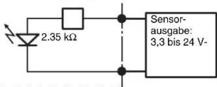
Pin 2, 4, 6, 8, 10, 12, 14, 16
(SENSOREINGANG-)
©2006 Sony Corporation
Marchi
natural_image
Technical line drawing of a mechanical rail conveyor system with pulleys and mounting brackets (no text or symbols)text_image
Technical diagram showing a ruler with measurement markings and an arrow indicating direction, likely for engineering or technical purposes.natural_image
Diagram of a computer drive rear panel with ports, connectors, and cable (no text or labels)natural_image
Diagram of a computer drive rear panel with ports and cables (no text or labels)Nota
natural_image
Diagram showing a computer fan connected to an RJ48 connector with multiple VGA connectors (no text or symbols present)Nota
text_image
Diagram of computer motherboard layout showing ports, connectors, and ventilation slots with labelsNota
natural_image
Back panel view of a computer drive showing fan, socket, connectors, and connector layout (no text or symbols)text_image
Non Setup Wizard Select Language Chinese Simplified English French German Italian Japanese Spanishtext_image
EULA The following "SOFTWARE LICENSE AGREEMENT" applies to the Program provided by Sorry. Please read the following "SOFTWARE LICENSE AGREEMENT" before using Network Surveillance Recorder (Model Name: NSR-50/100) (hereinafter referred to as the "Product"). By using the Product, you agree to the "SOFTWARE LICENSE AGREEMENT". Accept > Decline.text_image
Keyboard Layout Chinese-Simplified English French German Italian Japanese Spanishtext_image
General Network Setting Primary DNS 0 0 0 0 Secondary DNS 0 0 0 0 Default Gateway 0 0 0 0Primary DNS
IP Address: 192.168.[0/1/2]*.1
Netmask: 255.255.255.0
text_image
Host Name Host Name: NSR100_5048 Domain Name: localdomainHost Name
text_image
Summary Language: English Keyboard Layout: English Time Date: Asia/Time Date Time: Fri Dez 23 14:36.08 JST 2005 Default Gateway: 0.0.0.0 Primary DNS: 0.0.0.0 Secondary DNS: 0.0.0.0 NIC 1 Type: disk NIC 2 Type: Static NIC 2 IP Address: 192.168.1.1 NIC 2 Network: 255.253.255.0 NIC 3 Type: Statictext_image
NSR Setup Wizard Warning System will reboot to allow for new settings! Add Findtext_image
Network Security Monitor IPELA Camera to Setup Registered Camera Add Delete Model Address Posttext_image
Select Path 1. Select Path: Path to IP Path 2. Select Path: Path to IP Path 3. Select Path: Path to IP Path 4. Select Path: Path to IP Path 5. Select Path: Path to IP Path 6. Select Path: Path to IP Path 7. Select Path: Path to IP Path 8. Select Path: Path to IP Path 9. Select Path: Path to IP Path 10. Select Path: Path to IP Path 11. Select Path: Path to IP Path 12. Select Path: Path to IP Path 13. Select Path: Path to IP Path 14. Select Path: Path to IP Path 15. Select Path: Path to IP Path 16. Select Path: Path to IP Path 17. Select Path: Path to IP Path 18. Select Path: Path to IP Path 19. Select Path: Path to IP Path 20. Select Path: Path to IP Path 21. Select Path: Path to IP Path 22. Select Path: Path to IP Path 23. Select Path: Path to IP Path 24. Select Path: Path to IP Path 25. Select Path: Path to IP Path 26. Select Path: Path to IP Path 27. Select Path: Path to IP Path 28. Select Path: Path to IP Path 29. Select Path: Path to IP Path 30. Select Path: Path to IP Path 31. Select Path: Path to IP Path 32. Select Path: Path to IP Path 33. Select Path: Path to IP Path 34. Select Path: Path to IP Path 35. Select Path: Path to IP Path 36. Select Path: Path to IP Path 37. Select Path: Path to IP Path 38. Select Path: Path to IP Path 39. Select Path: Path to IP Path 40. Select Path: Path to IP Path 41. Select Path: Path to IP Path 42. Select Path: Path to IP Path 43. Select Path: Path to IP Path 44. Select Path: Path to IP Path 45. Select Path: Path to IP Path 46. Select Path: Path to IP Path 47. Select Path: Path to IP Path 48. Select Path: Path to IP Path 49. Select Path: Path to IP Path 50. Select Path: Path to IP Path 51. Select Path: Path to IP Path 52. Select Path: Path to IP Path 53. Select Path: Path to IP Path 54. Select Path: Path to IP Path 55. Select Path: Path to IP Path 56. Select Path: Path to IP Path 57. Select Path: Path to IP Path 58. Select Path: Path to IP Path 59. Select Path: Path to IP Path 60. Select Path: Path to IP Path 61. Select Path: Path to IP Path 62. Select Path: Path to IP Path 63. Select Path: Path to IP Path 64. Select Path: Path to IP Path 65. Select Path: Path to IP Path 66. Select Path: Path to IP Path 67. Select Path: Path to IP Path 68. Select Path: Path to IP Path 69. Select Path: Path to IP Path 70. Select Path: Path to IP Path 71. Select Path: Path to IP Path 72. Select Path: Path to IP Path 73. Select Path: Path to IP Path 74. Select Path: Path to IP Path 75. Select Path: Path to IP Path 76. Select Path: Path to IP Path 77. Select Path: Path to IP Path 78. Select Path: Path to IP Path 79. Select Path: Path to IP Path 80. Select Path: Path to IP Path 81. Select Path: Path to IP Path 82. Select Path: Path to IP Path 83. Select Path: Path to IP Path 84. Select Path: Path to IP Path 85. Select Path: Path to IP Path 86. Select Path: Path to IP Path 87. Select Path: Path to IP Path 88. Select Path: Path to IP Path 89. Select Path: Path to IP Path 90. Select Path: Path to IP Path 91. Select Path: Path to IP Path 92. Select Path: Path to IP Path 93. Select Path: Path to IP Path 94. Select Path: Path to IP Path 95. Select Path: Path to IP Path 96. Select Path: Path to IP Path 97. Select Path: Path to IP Path 98. Select Path: Path to IP Path 99. Select Path:Path to IIPPathPathPathPathPathPathPathPathPathPathPathPathPathPathPathPathPathPathPathPathPathPathPathPathPathPathPathPathPathPathPathPathPathPathPathPathPathPathPathPathPathPathPathPathPathPathPathPathPathPathPathPathPathPathPathPathPathPathPathPathPathPathPathPathPathPathPathPathPathPathPathPathPathPathPathPathPathPathPathPathPathPathPathPathPathPathPathPathPathPathPathPathPathPathPathPathPathPathPathPathLinetext_image
Parameters List: System settings: User: Windows User: Windows User: Windows User: Windows User: Windows User: Windows User: Windows User: Windows User: Windows User: Windows User: Windows User: Windows User: Windows User: Windows User: Windows User: Windows User: Windows User: Windows User: Windows User: Windows User: Windowstext_image
SONY IPELA File Edit View Insert Help Name: IPELA File Edit View Insert Help Name: IPELA File Edit View Insert Help Name: IPELA File Edit View Insert Help Name: IPELA File Edit View Insert Help Name: IPELA File Edit View Insert Help Name: IPELA File Edit View Insert Help Name: IPELA File Edit View Insert Help Name: IPELA File Edit View Insert Help Name: IPELA Data From: 123456780000000000000000000000000000000000000000000000000000000000000000000000000000000000000000000000000000 Source: IPELA Source: IPELA Source: IPELA Source: IPELA Source: IPELA Source: IPELA Source: IPELA Source: IPELA Source: IPELA Source: IPELA Source: IPELA Source: IPELA Source: IPELA Source: IPELA Source: IPELA Source: IPELA Source: IPELA Source: F12345678888888888888888888888888888888888888888888888888888888888888888888888888888888888888888888888888888text_image
The current said type is SPAN ○ SPAN ○ RAID 1 Cancel OKtext_image
Dollar run.tar.gz Dollar sur.tar.gz Create Data Raid..... (process:4410): G&R-WARNING **: Locale not supported by C Library (process:4419): Ctl-WARNING **: Locale not supported by C Library Using the fallback 'C' locale. ndade: /dev/nda7 appears to contain an cat2fs file system size:4567118888 prime:non Dec 5 23:59:00 2005 ndade: /dev/nda7 appears to be part of a raid array: level=1 devices=2 time=Non Aug 22 17:00:40 2005 ndade: /dev/ndb7 appears to be part of a raid array: level=1 devices=2 time=Non Aug 22 17:00:40 2005 Continue creating array*ndade: array /dev/nd5 started. Make arr3 filesystem..... Number of files installed : 8350 Used disk space : 348212 KB Press any key to continue!text_image
Clean System Restore Clean System Restore without Rebuilding Data Volume Clean System Restore with Changing RAID Types OS + Application Restore OS Only Restore Application Only Restore Restore Saved Configuration Reboot Shutdown| N. pin SENSOR IN | |||||
| 1 | 3 | . | 3 | v | |
| 2 | I | N | - | 8 | - |
| 3 | I | N | - | 8 | + |
| 4 | I | N | - | 7 | - |
| 5 | I | N | - | 7 | + |
| 6 | I | N | - | 6 | - |
| 7 | I | N | - | 6 | + |
| 8 | I | N | - | 5 | - |
| 9 | I | N | - | 5 | + |
| 10 IN_ | 4 - | ||||
| 11 IN_ | 4 + | ||||
| 12 IN_ | 3 - | ||||
| 13 IN_ | 3 + | ||||
| 14 IN_ | 2 - | ||||
| 15 IN_ | 2 + | ||||
| 16 IN_ | 1 - | ||||
| 17 IN_ | 1 + | ||||
| 18 GND | |||||
Alarm Out
| N. pin Alarm Out |
| 1 GND |
| 2 OUT_8 - |
| 3 OUT_8 + |
| 4 OUT_7 - |
| 5 OUT_7 + |
| 6 OUT_6 - |
| 7 OUT_6 + |
| 8 OUT_5 - |
| 9 OUT_5 + |
| 10 OUT_4 - |
| 11 OUT_4 + |
| 12 OUT_3 - |
| 13 OUT_3 + |
| 14 OUT_2 - |
| 15 OUT_2 + |
| 16 OUT_1 - |
| 17 OUT_1 + |
| 18 3.3 v |
Pin 3, 5, 7, 9, 11, 13, 15, 17 (SENSOR IN+)
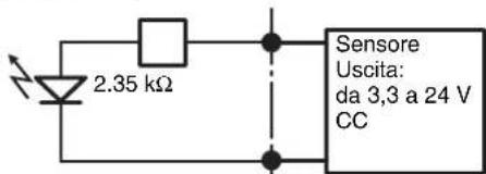
text_image
2.35 kΩ Sensore Uscita: da 3,3 a 24 V CCPin 2, 4, 6, 8, 10, 12, 14, 16 (SENSOR IN-)
©2006 Sony Corporation
Marcas comerciales
natural_image
Technical line drawing of a mechanical rail conveyor system with pulleys and mounting brackets (no text or symbols)natural_image
Technical line drawing of a ruler with an arrow indicating measurement direction (no text or symbols present)text_image
Riel interiornatural_image
Diagram of an internal computer drive bay with ports and connectors, showing no text or symbolsnatural_image
Line drawing of a computer tower rear panel with connectors and ventilation slots (no text or symbols)Nota
natural_image
Technical line drawing showing a fan connected to an RJ4 connector with multiple VGA connectors (no text or symbols present)Nota
text_image
Diagram of computer motherboard showing ports, connectors, and ventilation slots with labelsNota
natural_image
Front panel of a computer drive showing fan, socket, and various ports (no text or labels visible)text_image
NSR Setup Wizard Select Language Chinese Simplified English French German Italian Japanese Spanishtext_image
NSR Setup Wizard EULA The following "SOFTWARE LICENSE AGREEMENT" applies to the Program provided by Sony. Please read the following "SOFTWARE LICENSE AGREEMENT" before using Network Surveillance Recorder (Model Name: NSR-50/100) (hereinafter referred to as the "Product"). By using the Product, you agree to the "SOFTWARE LICENSE AGREEMENT". Accept > Decline OK Helptext_image
NSR Setup Wizard Keyboard Layout Chinese-Simplified English French German Italian Japanese Spanishtext_image
Date and Time Year Month Day 2005 12 13 Hour Minute 10 40 AM/FM C AM & PMAparecerá la pantalla [General Network Setting].
text_image
General Network Setting Primary DNS 0 0 0 0 Secondary DNS 0 0 0 0 Default Gateway 0 0 0 0Primary DNS
IP Address: 192.168.[0/1/2]*.1
Netmask: 255.255.255.0
text_image
Monitor #1 Model F Generic Monitor Dual Head Generic LCD Display: LCD Panel 3400-1/88 0.315 Generic CRT Display: Monitor 1024x768, 0.315-571 Generic CRT Display: Monitor 1024x768, 0.315-571 F Others Access: Access SLS, APPROCTS, 21.9 MΩ, 56.0 MΩ, 110.0 Access: Access SL, APPROCTS, 30.8 MΩ, 56.0 MΩ, 110.0 Access: Access SL, APPROCTS, 30.0 MΩ, 56.0 MΩ, 110.0 Access: Access SL, APPROCTS, 30.0 MΩ, 56.0 MΩ, 110.0 Resolution: 1024x768 +5% 5%Notas
text_image
Host Name Host Name: NSR100_5048 Domain Name: localdomainHost Name
text_image
MSN Setup Wizard Summary Language: English Keyboard Name: English Time Zone: Asia/Telaya Date Time: Fri Dec 23 14:36:08 JST 2005 Default Gateway: 0.0.0.0 Primary DNS: 0.0.0.0 Secondary DNS: 0.0.0.0 NIC 1 Type: Ship NIC 2 Type: Static NIC 2 IP Address: 192.168.1.3 NIC 2 Network: 255.255.255.0 NIC 3 Type: Static +/-text_image
NSM Setup Wizard Warning System will reboot to allow for new settings!text_image
Network Surveillance Register IPELA Camera to Setup Register Camera Add Enter Model Address Porttext_image
Customs Of History 1. New Document Options for IP Address File Path: 01-02-03 Format: 01-02-03 Format: 01-02-03 Format: 01-02-03 Format: 01-02-03 Format: 01-02-03 Format: 01-02-03 Format: 01-02-03 Format: 01-02-03 Format: 07-02-03 Format: 07-02-03 Format: 07-02-03 Format: 07-02-03 Format: 07-02-03 Format: 07-02-03 Format: 07-02-03 Format: 07-02-03 Format: 07-02- Format: 07-02- Format: 07-02- Format: 07-02- Format: 07-02- Format: 07-02- Format: 07-02- Format: 07-02- Format: 07-02- Format: 07-02- Format: 07-02- Format: 07-02- Formal Address: Formal Address: Format Address: Format Address: Format Address: Format Address: Format Address: Format Address: Format Address: Format Address: Format Address: Format Address: Format Address: Format Address: Format Address: Format Address: Format Address: Format Address: Format Address: Format Address: Format Address: Format Address: Format Address: Format Address: Format Address: Format Address: Format Address: Format Address: Format Address: Format Address: Format Address: Format Address: Format Address: Format Address: Format Address: Format Authority Format Authority Format Authority Format Authority Format Authority Format Authority Format Authority Format Authority Format Authority Format Authority Format Authority Format Authority Format Authority Format Authority Format Authority Format Authority Format Authority Format Authority Format Authority Format Authority Format Authority Format Authority Format Authority Format Authority Format Authority Format Authority Format Authority Format Authority Format Authority Format Authority Format Authority Format Authority Format Authority Format Authority Formal Address: Formal Address: Formal Address: Formal Address: Formal Address: Formal Address: Formal Address: Formal Address: Formal Address: Formal Address: Formal Address: Formal Address: Formal Address: Formal Address: Formal Address: Formal Address: Formal Address: Formal Address: Formal Address: Formal Address: Formal Address: Formal Address: Formal Address: Formal Address: Formal Address: Formal Address: Formal Address: Formal Address: Formal Address: Formal Address: Formal Address: Formal Address: Formal Address: Formal Address: Formal Address: Formal Address: Formal Address: Formal Address: Formal Address: Formal Address: Formal Address: Formal Address: Formal Address: Formal Address: Formal Address: Formal Address: Formal Address: Formal Address: Formal Address: Formal Address: Formal Address: Formal Address: Formal Address: Formal Address: Formal Address: Formal Address: Formal Address: Formal Address: Formal Address: Formal Address: Formal Address: Formal Address: Formal Address: Formal Address: Formal Address: Formal Address:text_image
Camera Profile Select Image Address: Warning if to select the appropriate settings,请单击 "Register" (Sub-Select) Show it to access: [ ] [ ] [ ] [ ] [ ] [ ] [ ] [ ] [ ] [ ] [ ] [ ] [ ] [ ] [ ] [ ] [ ] [ ] [ ] [ ] [ ] [ ] [ ] [ ] [ ] [ ] [ ] [ ] [ ] [ ] [ ] [ ] [ ] [ ] Reported Camera to Web Control to Image Select All Download 2 Images selected Camera to Web Check and link to Camera Name, Broadcast Image and Image Select Camera and Link Image / Text Set following settings to be selected Camera Add to Default Add to Default or Default Remove Camera OK Cancel (Off) Canceltext_image
IPELA IPO IPO IPO IPO IPO IPO IPO IPO IPO IPO IPO IPO IPO IPO IPO IPO IPO IPO IPO IPO IPO IPO IPO IPO IPO IPO IPO IPO IPO IPO IPO IPO IPO IPOtext_image
Clean System Restore Clean System Restore without Rebuilding Data Volume Clean System Restore with Changing RAID Types OS + Application Restore OS Only Restore Application Only Restore Restore Saved Configuration Reboot Shutdownstext_image
The current raid type is SPAN ● SPAN ○ RAID 1 Cancel OKtext_image
Data RAID rebuild completed! Status : Success Data Volume RAID Level : RAID 1 Data Volume Capacity : 218G Bytes Enter run.tar.gz Enter nor.tar.gz Create Data Raid..... (pruces:4416): GIL-WARNING **: locale not supported by C library (pruces:4416): GIL-WARNING **: Locale not supported by C library. Using the fallback 'C' locale. mdam: /dev/sda7 appears to contain an ext2Fs file system size=0587106RUX stime=Mon Dec 5 23:30:00 2005 mdam: /dev/sda7 appears to be part of a raid array: level=1 devices=2 stime=Mon Aug 22 17:08:40 2005 mdam: /dev/sdb7 appears to be part of a raid array: level=1 devices=2 stime=Mon Aug 22 17:08:40 2005 Continue creating array? mdam: array /dev/m5 started. Make ext3l filesystem..... Number of files installed : 8350 Used disk space : 348212 KB Press any key to continue !text_image
Clean System Restore Clean System Restore without Rebuilding Data Volume Clean System Restore with Changing RAID Types OS + Application Restore OS Only Restore Application Only Restore Restore Saved Configuration Reboot Shutdown| Número de clavija | SENSOR IN | |||
| 1 3.3 v | ||||
| 2 | I | N | - | 8 |
| 3 | I | N | - | 8 |
| 4 | I | N | - | 7 |
| 5 | I | N | - | 7 |
| 6 | I | N | - | 6 |
| 7 | I | N | - | 6 |
| 8 | I | N | - | 5 |
| 9 | I | N | - | 5 |
| 10 IN_4 - | ||||
| 11 IN_4 + | ||||
| 12 IN_3 - | ||||
| 13 IN_3 + | ||||
| 14 IN_2 - | ||||
| 15 IN_2 + | ||||
| 16 IN_1 - | ||||
| 17 IN_1 + | ||||
| 18 GND | ||||
Salida de alarma
| Número de clavija | Salida de alarma |
| 1 GND | |
| 2 OUT_8 - | |
| 3 OUT_8 + | |
| 4 OUT_7 - | |
| 5 OUT_7 + | |
| 6 OUT_6 - | |
| 7 OUT_6 + | |
| 8 OUT_5 - | |
| 9 OUT_5 + | |
| 10 OUT_4 - | |
| 11 OUT_4 + | |
| 12 OUT_3 - | |
| 13 OUT_3 + | |
| 14 OUT_2 - | |
| 15 OUT_2 + | |
| 16 OUT_1 - | |
| 17 OUT_1 + | |
| 18 3.3 v |
3, 5, 7, 9, 11, 13, 15, 17 clavijas (SENSOR IN+)
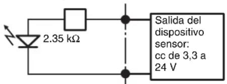
text_image
2.35 kΩ Salida del dispositivo sensor: cc de 3,3 a 24 V2, 4, 6, 8, 10, 12, 14, 16 clavijas (SENSOR IN-)
•©2006 Sony Corporation
商标
- “IPELA”和IPELA是Sony Corporation的商标。
natural_image
Technical line drawing of a mechanical rail or conveyor system with pulleys and mounting brackets (no text or symbols)text_image
Technical diagram showing a ruler with measurement markings and an arrow indicating direction, likely for engineering or technical purposes.natural_image
Diagram of a computer drive rear panel with connectors and ports, showing cable connections (no text or labels)natural_image
Line drawing of a computer tower rear panel with connectors and ventilation slots (no text or symbols)注
natural_image
Technical line drawing showing a fan connected to an VGA socket with connectors (no text or symbols)注
text_image
Diagram of computer motherboard layout showing CPU socket, RAM slots, and ventilation connections注
natural_image
Diagram of computer hardware components including fan, socket, connectors, and drive slots (no text or labels)text_image
Select Language Chinese Simplified English French German Italian Japanese Spanish出现 [EULA] 屏幕。
text_image
NSR Setup Wizard EULA The following "SOFTWARE LICENSE AGREEMENT" applies to the Program provided by Sony. Please read the following "SOFTWARE LICENSE AGREEMENT" before using Network Surveillance Recorder (Model Name: NSR-50/100) (hereinafter referred to as the "Product"). By using the Product, you agree to the "SOFTWARE LICENSE AGREEMENT". ○ Accept ▼ Declinetext_image
Keyboard Layout Chinese-Simplified English French German Italian Japanese Spanish出现 [Time Zone] 屏幕。
text_image
Date and Time Year Month Day 2005 12 13 Hour Minute 10 40 AM/FM C AM & FM + Back Stop -text_image
General Network Setting Primary DNS 0 0 0 0 Secondary DNS 0 0 0 0 Default Gateway 0 0 0 0Primary DNS
IP Address: 192.168.[0/1/2]*.1
Netmask: 255.255.255.0
text_image
Monitor #1 Model □ Dual Head □ Generic Monitor Genetic LCD Display, LCD Panel 100x120K: 0.315 Genetic CRT Display, Monitor 1024x768: 0.315-57.1 □ Others New Array 55A, AP/PC/OS, 30.0-5.5, 50.0-110.0 New Array 55C, AP/PC/OS, 30.0-5.5, 52.0-60.0 New Array 55D, AP/PC/OS, 30.0-5.4, 53.0-110.0 New Array 55E, AP/PC/OS, 30.0-6.4, 59.0-110.0 New Array 55F, AP/PC/OS, 30.0-7.0, 50.0-110.0 Resolution: 1024x768 □ Full □ No -注
- 显示器的默认设置如下。
text_image
Host Name Host Name: NSR100_5048 Domain Name: localdomainHost Name
输入主机名。
注
text_image
Summary Language: English Keyboard layout: English TimeZone: Asia/Taiyo Date Time: Fri Dec 23 14:36:09_JST 2005 Default Gateway: 0.0.0.0 Primary DNS: 0.0.0.0 Secondary DNS: 0.0.0.0 ABC 1 Type: .disc ABC 2 Type: Static ABC 2 IP Address: 192.168.1.1 ABC 2 Network: 255.255.255.0 ABC 3 Type: Static出现 [Warning] 屏幕。
13 单击 [完成]。

text_image
NSR Setup Wizard Warning System will reboot to allow for new settings!NSR 将自动重启。
text_image
Internet Surveillance Security IPELA Current to Setup Request Camera Add Delete Model Address Porttext_image
Configuration Set to all stored options: Name: "Name" or "Address" or "Address Name" or "Address Address" or "Address Date" or "Date Time" Name: "Name" or "Address" or "Address Name" or "Address Address" or "Address Date" or "Date Time" Description: Custom to this URL Custom to be registered Subtitle Description of 1. Description is added to the website 2. Check and write common text, additional text and documents. 3. Use common text and other documents in the website. 4. Use common text and other documents in the website. 5. Use common text and other documents in the website. 6. Use common text and other documents in the website. 7. Use common text and other documents in the website. 8. Use common text and other documents in the website. 9. Use common text and other documents in the website. 10. Use common text and other documents in the website. 11. Use common text and other documents in the website. 12. Use common text and other documents in the website. 13. Use common text and other documents in the website. 14. Use common text and other documents in the website. 15. Use common text and other documents in the website. 16. Use common text and other documents in the website. 17. Use common text and other documents in the website. 18. Use common text and other documents in the website. 19. Use common text and other documents in the website. 20. Use common text and other documents in the website. 21. Use common text and other documents in the website. 22. Use common text and other documents in the website. 23. Use common text and other documents in the website. 24. Use common text and other documents in the website. 25. Use common text and other documents in the website. 26. Use common text and other documents in the website. 27. Use common text and other documents in the website. 28. Use common text and other documents in the website. 29. Use common text and other documents in the website. 30. Use common text and other documents in the website. 31. Use common text and other documents in the website. 32. Use common text and other documents in the website. 33. Use common text and other documents in the website. 34. Use common text and other documents in the website. 35. Use common text and other documents in the website. 36. Use common text and other documents in the website. 37. Use common text and other documents in the website. 38. Use common text and other documents in the website. 39. Use common text and other documents in the website. 40. Use common text and other documents in the website. 41. Use common text and other documents in the website. 42. Use common text and other documents in the website. 43. Use common text and other documents in the website. 44. Use common text and other documents in the website. 45. Use common text and other documents in the website. 46. Use common text and other documents in the website. 47. Use common text and other documents in the website. 48. Use common text and other documents in the website. 49. Use common text and other documents in the website. 50. Use common text and other documents in the website. 51. Use common text and other documents in the website. 52. Use common text and other documents in the website. 53. Use common text and other documents in the website. 54. Use common text and other documents in the website. 55. Use common text and other documents in the website. 56. Use common text and other documents in the website. 57. Use common text and other documents in the website. 58. Use common text and other documents in the website. 59. Use common text and other documents in the website. 60. Use common text and other documents in the website. 61. Use common text and other documents in the website. 62. Use common text and other documents in the website. 63. Use common text and other documents in the website. 64. Use common text and other documents in the website. 65. Use common text and other documents in the website. 66. Use common text and other documents in the website. 67. Use common text and other documents in the website. 68. Use common text and other documents in the website. 69. Use common text and other documents in the website. 70. Use common text and other documents in the website. 71. Use common text and other documents in the website. 72. Use common text and other documents in the website. 73. Use common text and other documents in the website. 74. Use common text and other documents in the website. 75. Use common text and other documents in the website. 76. Use common text and other documents in the website. 77. Use common text and other documents in the website. 78. Use common text and other documents in the website. 79. Use common text and other documents in the website. 80. Use common text and other documents in the website. 81. Use common text and other documents in the website. 82. Use common text and other documents in the website. 83. Use common text and other documents in the website. 84. Use common text and other documents in the website. 85. Use common text and other documents in the website. 86. Use common text and other documents in the website. 87. Use common text and other documents in the website. 88. Use common text and other documents in the website. 89. Use common text and other documents in the website. 90. Use common text and other documents in the website. 91. Use common text and other documents in the website. 92. Use common text and other documents in the website. 93. Use common text and other documents in the website. 94. Use common text and other documents in the website. 95. Use common text and other documents in the website. 96. Use common text and other documents in the website. 97. Use common text and other documents in the website. 98. Use common text and other documents in the website. 99. Use common text and other documents in the website. 100. Use common text and other documentstext_image
IPELA IPO IPO IPO IPO IPO IPO IPO IPO IPO IPO IPO IPO IPO IPO IPO IPO IPO IPO IPO IPO IPO IPO IPO IPO IPO IPO IPO IPO IPO IPO IPO IPO IPO IPOtext_image
Clean System Restore Clean System Restore without Rebuilding Data Volume Clean System Restore with Changing RAID Types OS + Application Restore OS Only Restore Application Only Restore Restore Saved Configuration Reboot Shutdown出现 “RAID 类型” 选择屏幕。
text_image
The current raid type is SPAN ○ SPAN ○ RAID 1 Cancel OK出现确认屏幕。
6 单击 [OK]。
text_image
Data RAID rebuild completed! States : Success Data Volume RAID Level : RAID 1 Data Volume Capacity : 218G Bytes OK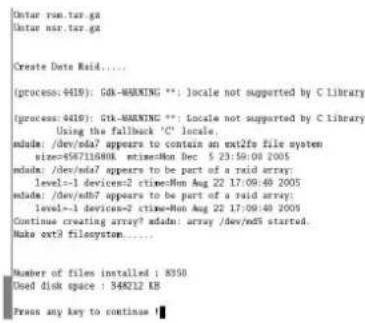
text_image
Ontar run.tar.gz Ontar nsr.tar.gz Create Data Raid..... (process: 4419): GB-WARNING **; locale not supported by C Library (process: 4419): Gk-WARNING **; Locale not supported by C Library. Using the fallback 'C' locale. sada: /dev/ada? appears to contain an ext2fx file system size=6587116808, stime=Mon Dec 5 23:59:00 2005 sada: /dev/ada? appears to be part of a ravid array: level=1 device=2 stime=Mon Aug 22 17:09:49 2005 sada: /dev/ada? appears to be part of a ravid array: level=1 device=2 stime=Mon Aug 22 17:09:49 2005 Continue creating array? sada: array /dev/ada started Sub ext2 filesystem..... Number of files installed : 8350 Used disk space : 348212 KB Press any key to continue ■text_image
Clean System Restore Clean System Restore without Rebuilding Data Volume Clean System Restore with Changing RAID Types OS + Application Restore OS Only Restore Application Only Restore Restore Saved Configuration Reboot Shutdowns如果确实出现该屏幕,请按以下步骤操作。
1 单击 [关机],关闭 NSR。
text_image
NSR-100 Menu * 1. Hardware diagnostic utility * 2. Check file system * 3. Restore DOM image * 4. Get system log * 5. Install tool rpm packages * 6. Reboot the system * 7. Shutdown the system * Enter your choice:检查文件系统可能需要几个小时。
| 插针编号 | 传感器输入 | ||||
| 1 | 3 | . | 3 | v | |
| 2 | I | N | - | 8 | - |
| 3 | I | N | - | 8 | + |
| 4 | I | N | - | 7 | - |
| 5 | I | N | - | 7 | + |
| 6 | I | N | - | 6 | - |
| 7 | I | N | - | 6 | + |
| 8 | I | N | - | 5 | - |
| 9 | I | N | - | 5 | + |
| 10 IN_4 - | |||||
| 11 IN_4 + | |||||
| 12 IN_3 - | |||||
| 13 IN_3 + | |||||
| 14 IN_2 - | |||||
| 15 IN_2 + | |||||
| 16 IN_1 - | |||||
| 17 IN_1 + | |||||
| 18 GND | |||||
Alarm Out
| 插针编号 | 警报输出 |
| 1 GND | |
| 2 OUT_8 - | |
| 3 OUT_8 + | |
| 4 OUT_7 - | |
| 5 OUT_7 + | |
| 6 OUT_6 - | |
| 7 OUT_6 + | |
| 8 OUT_5 - | |
| 9 OUT_5 + | |
| 10 OUT_4 - | |
| 11 OUT_4 + | |
| 12 OUT_3 - | |
| 13 OUT_3 + | |
| 14 OUT_2 - | |
| 15 OUT_2 + | |
| 16 OUT_1 - | |
| 17 OUT_1 + | |
| 18 3.3 v |
使用 I/O 插孔
Printed on recycled paper.
Sony Corporation 1-7-1 Konan, Minato-ku, Tokyo, 108-0075, Japan
http://www.sony.net/
Printed in Japan