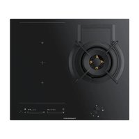
KIG6850.0SR - Hob Küppersbusch - Free user manual and instructions
Find the device manual for free KIG6850.0SR Küppersbusch in PDF.


| Brand | Küppersbusch |
| Model | KIG6850.0SR |
| Product type | Gas/induction hob |
| Number of burners/zones | 5 (1 dual crown gas burner, 2 standard induction, 2 flex induction) |
| DUAL gas burner | Ultra-fast, 6000 W, with independently adjustable inner flame |
| Induction zone 1 | ∅ 15,0 cm, 1200/1600 W |
| Induction zone 2 | ∅ 21,5 cm, 2100/3000 W |
| Flex induction zone 3 | 22,8 x 20,0 cm, 1750/2000 W |
| Flex induction zone 4 | 22,8 x 20,0 cm, 1750/2000 W |
| Electrical supply | 230 V ~ 50 Hz, single-phase |
| Gas supply | G20 (20 mbar), G30 (28-30 mbar), G31 (37 mbar) |
| Appliance dimensions (W x D) | 800 x 500 mm (estimated) |
| Weight | Approximately 15 kg |
| Chef special functions | Keep warm, Melting, Simmering, Rapid boil, Sliding cooking, Grill, Pan frying, Deep frying, Confit, Poaching |
| Flex Zone function | Allows coupling two induction zones for a large cooking surface |
| Power (Booster) function | Available on induction zones, limited duration |
| Timer | Programmable countdown from 1 to 99 minutes |
| Child lock | Block function locking touch controls |
| Pan detection | Automatic shut-off if pan is absent or unsuitable |
| Safety shut-off | Automatic disconnection after a set time depending on power level |
| Cleaning and maintenance | Ceramic glass surface: clean with damp cloth or specific product, scraper for baked-on residues. Do not use steam cleaner. |
| Spare parts | Replacement injectors for different gases, power cable |
Frequently Asked Questions - KIG6850.0SR Küppersbusch
User questions about KIG6850.0SR Küppersbusch
0 question about this device. Answer the ones you know or ask your own.
Ask a new question about this device
Download the instructions for your Hob in PDF format for free! Find your manual KIG6850.0SR - Küppersbusch and take your electronic device back in hand. On this page are published all the documents necessary for the use of your device. KIG6850.0SR by Küppersbusch.
USER MANUAL KIG6850.0SR Küppersbusch
natural_image
Two identical grid diagrams with white circles at intersections, no text or symbols presentKIG6850.0SR
KIG9850.0SR
Please read the users and installation instructions carefully before installation of the appliance and before starting to use it.
natural_image
Line drawings of two cooking pots with crossed handles and a heating element, no text or symbols presentFig. 1


natural_image
Line drawing of a hand using a tool to clean or inspect a circular component (no text or symbols)Fig. 6
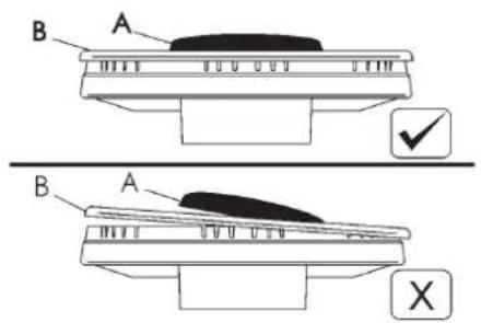
Fig. 7 Fig. 8

natural_image
Close-up of a metallic mechanical component with a circular feature and labeled point E (no text or symbols beyond label)Fig. 5
natural_image
Diagram of a curved pipe or duct with a base and labeled point B, no text or symbols present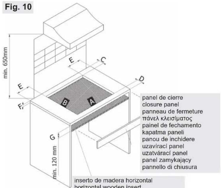
inserto de madera horizontal
horizontal wooden insert
inserte en bois horizontal
οριζόντια ξύλινη θήκη
inserção de madeira horizontal
yatay ahşap uç
insert orizontal din lemn
horizontální dřevěná vložka
horizontálna drevená vložka
pozioma drewniana wstawka
inserto orizzontale in legno
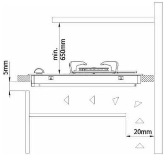
medidas que es preciso respetar (en mm)
comply with the dimensions (in mm)
dimensions a respecter (en mm)
μεγεθη που πρεπει να τηρηθουν (σε mm)
medidas a respeitar (en mm)
boyutlara uyun (mm cinsinden)
respecta dimensiunile (in mm)
dodržet rozměry (v mm)
vyhovovat' rozmerom (v mm)
zgodne z wymiarami (w mm)
misure da rispettare (in mm)
ABCDEFG
60 cm. 560 490 55 55 60 min. 30 - max 50 min. 120 mm
90 cm. 860 490 55 55 60 min. 30 - max 50 min. 120 mm
Cajón de los cubiertos / cutlery drawer / tiroir à couverts / συρτάρι για μαχαιροπίρουνα / gaveta de talheres / çatal biçak çekmecesi / sertar pentru tacâmuri / zásuvka na pribory / priborová zásuvka / szuflada na sztućce / cassetto delle posate
horno / oven / four / Φούρνος / forno / fırın / cuptor / trouba / rúra / piekarnik / forno
natural_image
Line drawing of a kitchen appliance with ovens and a stove (no text or symbols)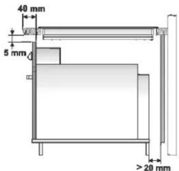
4 quemadores de gas
4 gas burners
4 brûleurs à gaz
4 καπνιστες αεριου
4 queimadores de gás
4 gaz brülörü
4 arzatoare pe gaz
4 plynové hořáky
4 plynové horáky
4 palniki gazowe
4 fuochi a gas
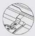
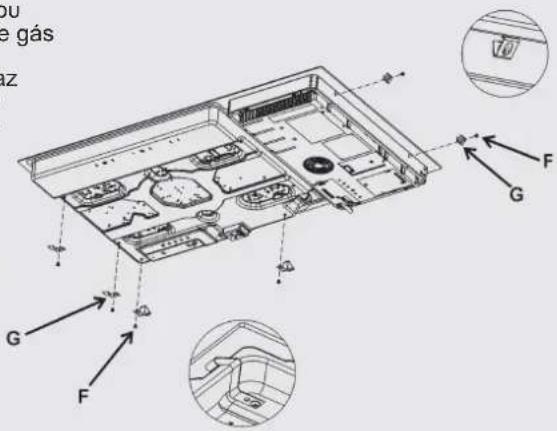
Fig. 11
natural_image
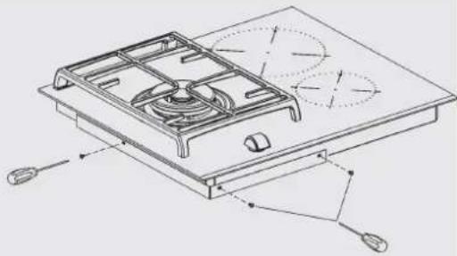
Technical line drawing of a gas stove with cooling fans and mounting base (no text or symbols)WARNING! In the need to disassemble the hob, fi rst remove the screw on the bottom, as shown in the figure to side!
Fig. 16
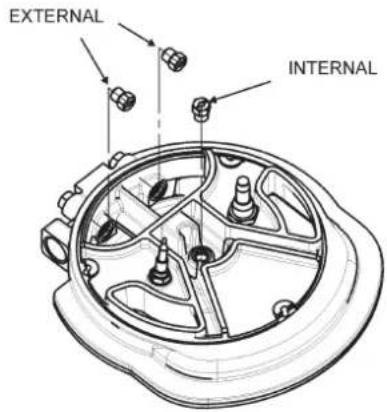
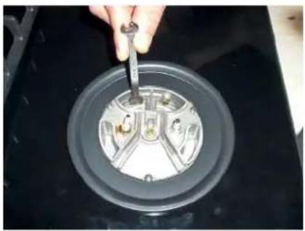
Fig. 18 Fig. 19
natural_image
Close-up of a hand using a tool to adjust or install a circular mechanical component on a dark surface (no visible text or symbols)
flowchart
graph TD
    A["①"] --> B["②"]
    C["③"] --> D["⑤"]
    E["④*"] --> F["②"]
    G["⑥"] --> H["⑦*"]
    I["⑧"] --> J["⑩*"]
    K["⑪"] --> L["⑪*"]
    M["⑫"] --> N["⑬*"]
    O["⑬"] --> P["⑭*"]
    Q["⑮"] --> R["⑯*"]
    S["⑰"] --> T["⑱*"]
    U["⑲"] --> V["⑳*"]
    W["⑳"] --> X["㉑*"]
    Y["㉒"] --> Z["㉓*"]
    AA["㉔"] --> AB["㉕*"]
    AC["㉖"] --> AD["㉗*"]
    AE["㉘"] --> AF["㉙*"]
    AG["㉚"] --> AH["㉛*"]
    AI["㉜"] --> AJ["㉝*"]
    AK["㉞"] --> AL["㉟*"]
    AM["㉟"] --> AN["㉟*"]
    AO["㉟"] --> AP["㉟*"]
    AQ["㉟"] --> AR["㉟*"]
    AS["㉟"] --> AT["㉟*"]
    AU["㉟"] --> AV["㉟*"]
    AW["㉟"] --> AX["㉟*"]
    AY["16"] --> Z
    AZ["10"] --> AA
    BA["11"] --> BB
    BC["14"] --> BC
    BD["15"] --> BC
    BE["-"] --> BF["-"]
    BG["-"] --> BH["-"]
    BI["-"] --> BJ["-"]
    BK["-"] --> BL["-"]
    BM["-"] --> BN["-"]
    BO["-"] --> BP["-"]
    BP["-"] --> BQ["-"]
    BR["-"] --> BS["-"]
    BT["-"] --> BU["-"]
    BV["-"] --> BW["-"]
KIG9850.0SRKIG6850.0SR
QUEMADOR "DUAL"
natural_image
Top-down view of a rectangular appliance with a circular vent and side handles (no text or symbols visible)
Fig. 24
natural_image
Two black cooking panes with visible steam pipes and handles, shown against white background (no text or symbols)Fig. 25
natural_image
Three identical cooking pots with checkmark and cross symbols below (no text or labels)Fig. 26
Fig. 29
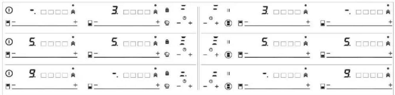
Fig. 30
natural_image
Illustration of a stainless steel cooking pan with a handle and two arrows pointing to it (no text or symbols)Warning. If the ceramic glass breaks or cracks, immediately unplug the stovetop to avoid electric shocks.
This appliance is not designed to work with an external timer (not built into the appliance) or a separate remote control system.
Do not steam clean this device.
Warning. The device and its accessible parts may heat up during operation. Avoid touching the heating elements. Children younger than 8 years old must stay away from the hob unless they are permanently supervised.
This device may solely be used by children 8 years old or older, people with impaired physical, sensory or mental abilities, or those who lack experience and knowledge, ONLY when supervised or if they have been given adequate instruction on the use of the device and understand the dangers its use involves. User cleaning and maintenance may not be done by unsupervised children.
Children must not play with the device.
Warning. It is dangerous to cook with fat or oil without being present, as these may catch fire. NEVER try to extinguish a fire with water! In this event disconnect the device and cover the flames with a lid, a plate or a blanket.
Do not store any object on the cooking areas
of the induction hob. Prevent possible fire hazards.
The induction generator complies with current EU legislation We however recommend that anyone fitted with a device such as a pacemaker should refer to their physician, or if in doubt abstain from using the induction areas.
Metal object such as knives, forks, spoons and lids may not be placed on the surface of the hob as they may overheat.
After use always disconnect the hot plate, do not simply remove the pot or pan. Otherwise a malfunction may occur if inadvertently another pot or pan is placed on it within the detection period. Prevent possible accidents!
If the supply cord is damaged, it must be replaced by the manufacturer, its service agent or similarly qualified persons in order to avoid hazard.
WARNING: Use only stovetop protectors designed by appliance manufacturer or indicated by the manufacturer in the instructions for use as adequate or stovetop protectors incorporated into the device. The use of inadequate protectors can cause accidents.
It is necessary to allow the appliance disconnection after installation. Disconnection devices must be incorporated to the fixed electrical installation, according to the installation regulations.
⚠️For a proper cleaning, see cleaning instructions.
CAUTION: The cooking process has to be supervised. A short term cooking process has to be supervised continuously.
WARNING! The manufacturer will not be liable for any damage caused by the alteration or modification of the product or its components during the installation. The installer will be liable for any damages or faults occurred for the incorrect assembly or installation. For any damages resulting from the installation of the product, please contact the authorized installer.
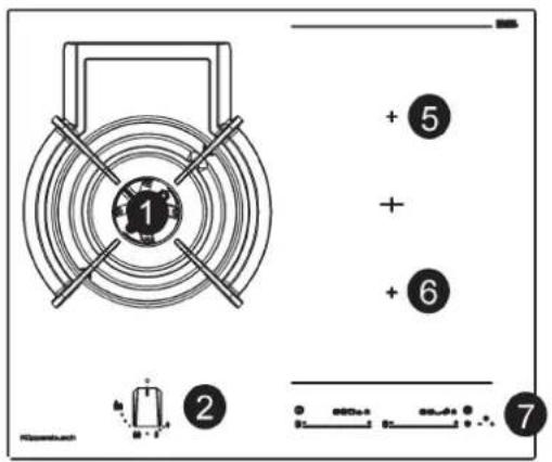
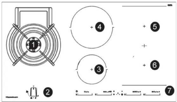
KIG9850.0SRKIG6850.0SR
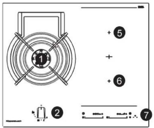
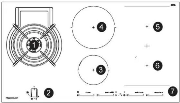
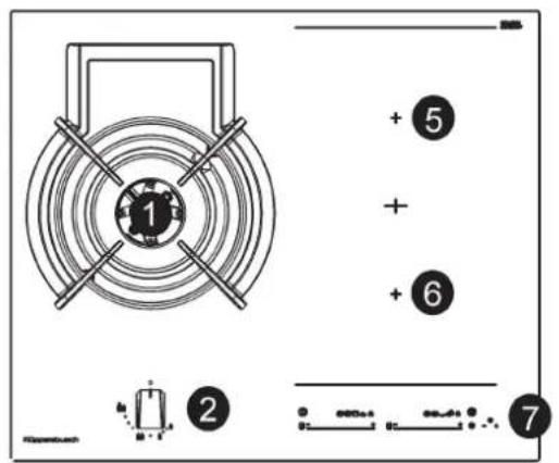
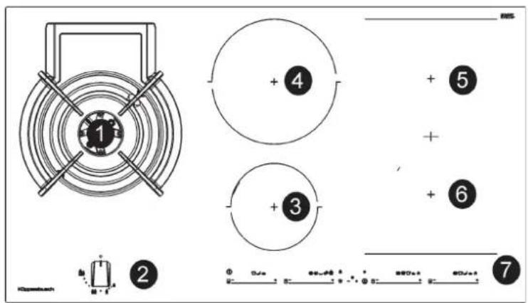
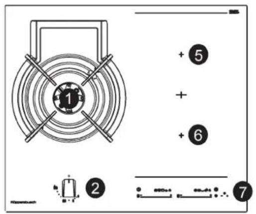
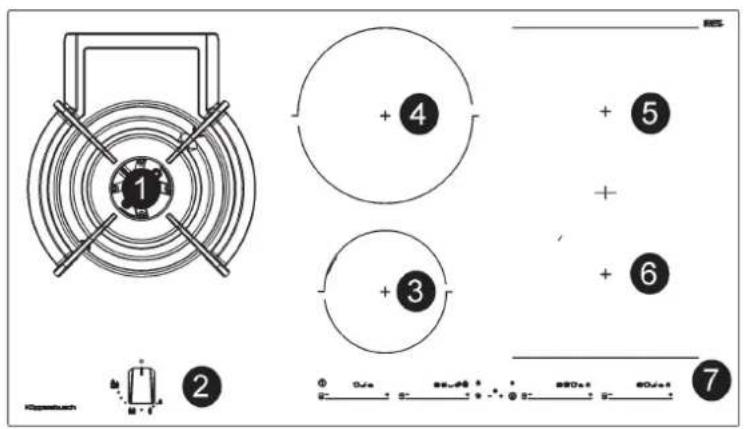
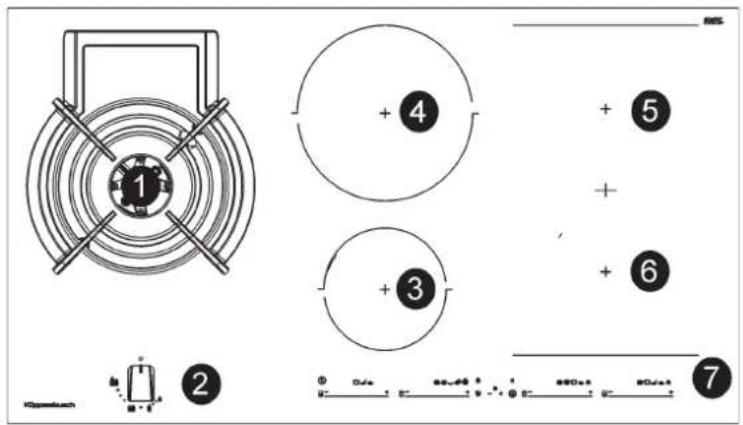
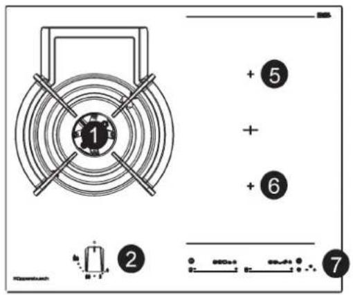
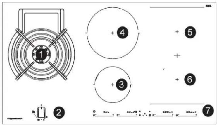
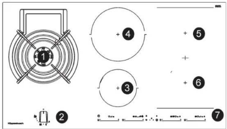
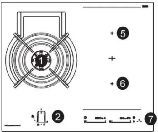
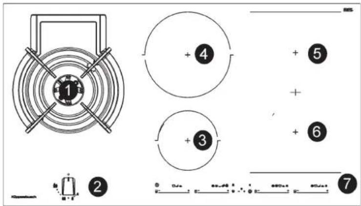
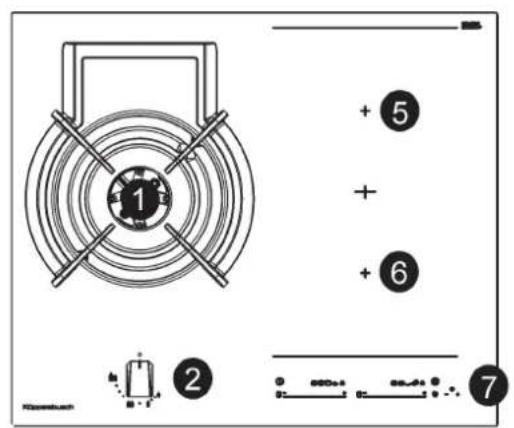
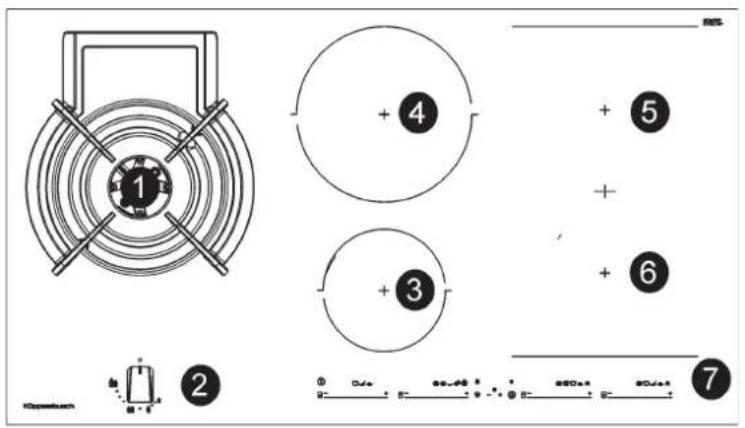
1 Ultra rapid gas burner DUAL
of 6000 W
2 Burner control knob
3 Electric heating element induction ∅ 15,0 cm of 1200/1600 W
4 Electric heating element induction ∅ 21,5 cm of 2100/3000 W
5 Heating element ind. fl ex 22.8X20.0 cm of 1750/2000 W
6 Heating element ind. fl ex 22.8X20.0 cm of 1750/2000 W
7 Touch control
Attention: this appliance has been manufactured for domestic use only and it employment by private person.
DUAL
Fig. 22
Burners ∅ pans cm.
DUAL total 22 ÷ 30
DUAL central 12 ÷ 16
MAX EXT
MAX INT


OFF
natural_image
Simple geometric diagram showing a circle with a small circle inside, no text or symbols present.O
0
O

MIN INT
DUAL BURNERS
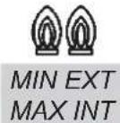
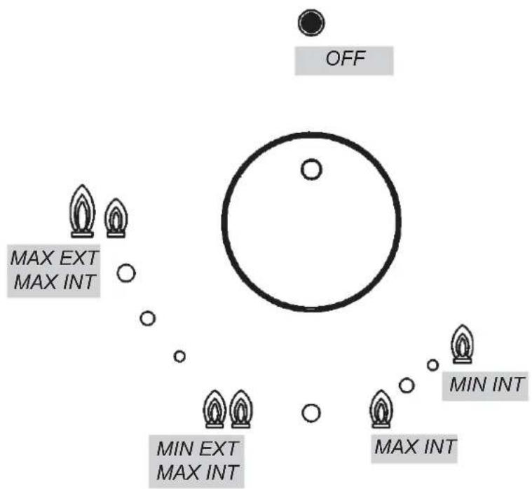
Separate regulation of the inner and outer rings (in practical terms, a dual burner controlled by a single knob), offering very flexible use thanks to the possibility to light either the inner flame only or the whole burner (inner and outer flame at the same time).
LIGHTING AND USING THE "DUAL" BURNER
Stand the pan on the burner before lighting.
Despite being controlled by a single knob (fi g. 22), the "DUAL" burner can be used in two different ways.
A) - Using the complete burner: starting from the off position • You must first press the knob, simultaneously turning it anticlockwise,
until the indicator points to the ma xi mu m de li ve ry p os it io n obtaining the maximum flow capacity of both fl ames.
When the flames are lit, keep the knob pressed for a few seconds, until the device automatically keeps the burner lit.
It is now possible to regulate the intensity of the flame by turning the knob anti-clockwise (from the maximum flow capacity position of the inner and outer flames to the maximum flow capacity of the inner flame and the minimum of the outer flame.
To turn off the burner, turn the knob clockwise, realigning the indicator with the • off symbol.
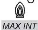
B) - Using the inner flame only: after lighting the burner and regulating the inner flame to maximum flow capacity and the outer flame to minimum flow capacity as described above, turn the knob anti-clockwise until it clicks once. The inner flame is now at maximum flow capacity while the outer flame is turned off.
Continue turning anti-clockwise to regulate the inner fl ame to the minimum flow capacity.
Turning off :
to turn off the burner, turn the knob clockwise, realigning the indicator with the • off symbol.
Once the “DUAL” burner is operating in either of the two modes described, it is possible to swap from one mode to the other by simply turning the knob to the position required.
IMPORTANT WARNINGS FOR THE USER
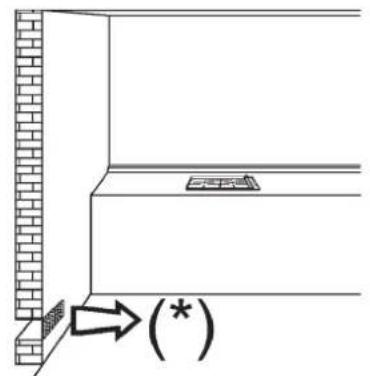
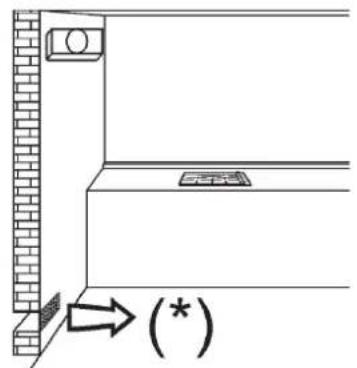
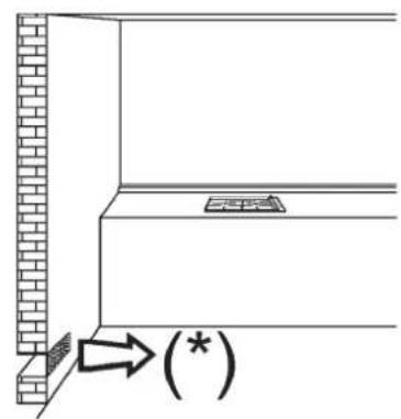
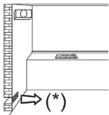
- Use of a gas cooking appliance produces heat and moisture in the room in which it is installed. The room must therefore be well ventilated by keeping the natural air vents clear (see fi g. 2) and by activating the mechanical aeration device (suction hood or electric fan fi g. 3 and fi g. 4).
- Intensive and lengthy use of the appliance may require additional ventilation. This can be achieved by opening a window or by increasing the power of the mechanical exhausting system if installed.
- Do not attempt to change the technical characteristics of the product because it can be dangerous.
- If you should not to use this appliance any more (or replace an old model), before disposing of it, make it inoperative in conformity with current law on the protection of health and the prevention of environmental pollution by making its dangerous parts harmless, especially for children who might play on an abandoned appliance.
- Do not touch the appliance with wet or damp hands or feet.
- Do not use the appliance barefoot.
- The manufacturer will not be liable for any damage resulting from improper, incorrect or unreasonable use.
- During, and immediately after operation, some parts of the cook top are very hot: avoid touching them.
- After using the cook top, make sure that the knob is in the closed position and close the main tap of the gas supply or gas cylinder.
- If the gas taps are not operating correctly, call the Service Department.
IMPORTANT:
always disconnect the appliance
from the gas and electricity mains before carrying out any cleaning operation.
HOT PLATE
It is very important to clean the surface soon after every use, when the glass is still tepid.
Do not use metallic sponges, powder abrasives or corrosive sprays.
Depending on the dirty level we recommend:
- slights stains: it is enought the use of a moist clean rag.
- Marks of liquid, overflowed from the pot, can be removed using vinegar or lemon.
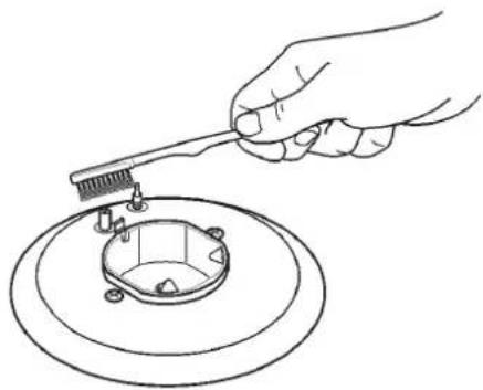
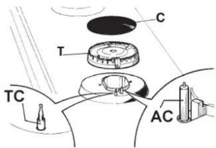
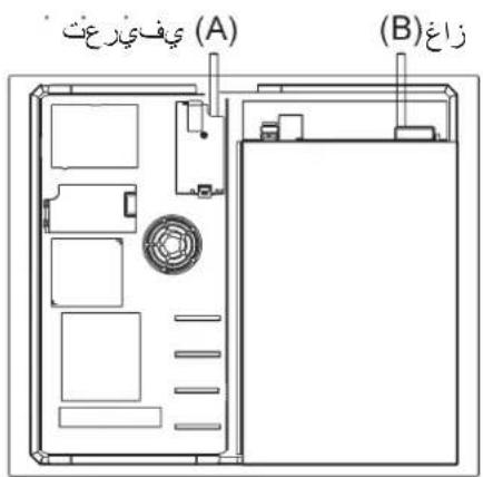
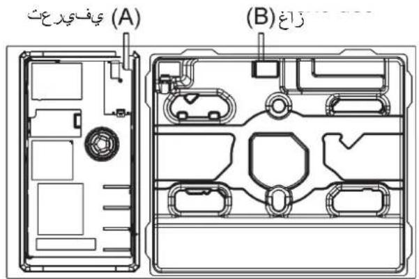
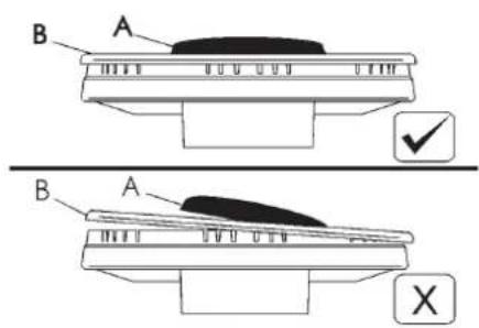
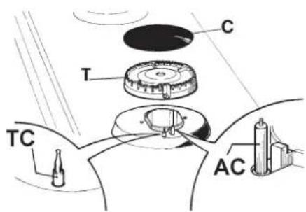
Periodically wash the hot plate, the enamelled stell pan support, the enamelled burner caps "A", "B" and "C" and the burner heads "T" (see fi g. 7 and 8) with lukewarm soapy water. They should also be cleaned plugs "AC" and flame detection "TC" (see fi g. 8).
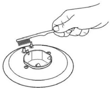
Clean them gently with a small nylon brush as shown (see fi g. 6) and allow to dry fully.
Do not wash in the dishwasher.
Do not allow vinegar, coffee, milk, salted water, lemon or tomato juice from remaining in contact with the enamelled surfaces for long periods of time.
WARNINGS:
comply with the following instructions, before remounting the parts:
- check that burner head slots "T" (fig. 8) have not become clogged by foreign bodies.
- Check that enamelled burner cap "A", "B", "C" (fi g. 7 and 8) have correctly positioned on the burner head. It must be steady.
- The pan support must be placed in the appropriate centering pins verifying the perfect stability.
- Do not force the taps if they are difficult open or close. Contact the technical assistance service for repairs.
- Don't use steam jets for the equipment cleaning.
CAUTION:
In case of hotplate glass breakage:
- shut immediately off all burners and any electrical heating element and isolate the appliance from the power supply;
- do not touch the appliance surface;
- do not use the appliance.
Note: continuous use could cause the burners to change colour due to the high temperature.
within children's reach since they could become potential sources of danger.
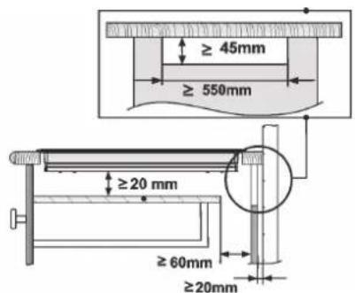
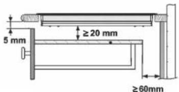
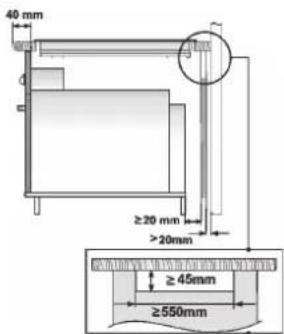
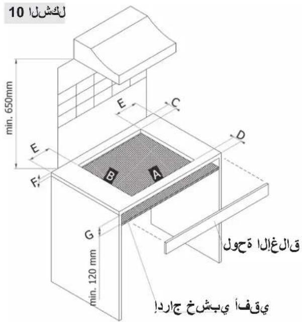
The measurements of the opening made in the top of the modular cabinet and into which the hot plate will be installed are indicated in either fi g. 10. Always comply with the measurements given for the hole into which the appliance will be recessed (see fi g. 10).
The appliance belongs to class 3 and is therefore subject to all the provisions established by the provisions governing such appliances.
TECHNICAL INFORMATION FOR THE INSTALLER
Installation, adjustments of controls and maintenance must only be carried out by a qualified engineer.
The appliance must be correctly installed in conformity with current law and the manufacturer's instructions. Incorrect installation may cause damage to persons, animals or property for which the Manufacturer shall not be considered responsible.
During the life of the system, the automatic safety or regulating devices on the appliance may only be modified by the manufacturer or by his duly authorized dealer.
INSTALLING THE HOT PLATE
Check that the appliance is in a good condition after having removed the outer packaging and internal wrappings from around the various loose parts. In case of doubt, do not use the appliance and contact qualified personnel. Never leave the packaging materials (cardboard, bags, polystyrene foam, nails, etc.)
FIXING THE HOT PLATE
The hot plate has a special seal which prevents liquid from infiltrating into the cabinet.
Strictly comply with the following instructions in order to correctly apply this seal:
- take off all the movable parts of the hob.
- Cut the seal in 4 parts of the necessary length to positioning it on the 4 edges of the crystal.
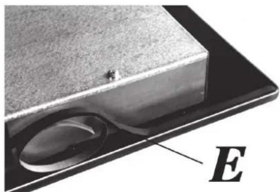
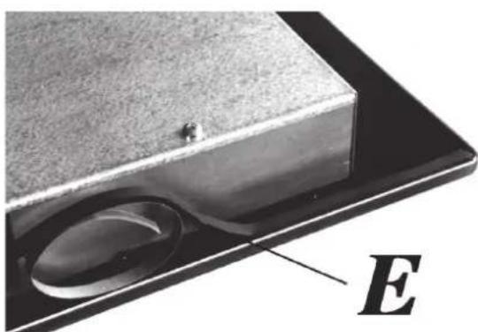
- Overturn the hot plate and correctly position seal "E" (fi g. 5 under the edge of the hot plate itself, so that the outer side of the seal perfectly matches the outer perimetral edge of the crystal. The ends of the strips must fi t together without overlapping.
- Evenly and securely fi x the seal to the crystal, pressing it in place with the fi ngers.
- Position the hob in the hole in the unit and fasten it in place using the appropriate screws "F" of the fastening hooks "G" (see fig. 11 and 12).
- In order to avoid accidental touch with the overheating bottom of the hob, during the working, is necessary to put a wooden insert, fixed by screws, at a minimum distance of 120 mm from the top (see fig. 10).
IMPORTANT INSTALLATION Openable window or alternative INSTRUCTIONS
The installer should note that the appliance that side walls should be no higher than
the hot plate itself. Furthermore, the rear wall, the surfaces surrounding and adjacent to the appliance must be able to withstand an temperature of 90°C.
The adhesive used to stick the plastic laminate to the cabinet must be able to withstand a temperature of not less than 150 °C otherwise the laminate could come unstuck.
The appliance must be installed in compliance with BS 6172 1990, BS 5440 part. 2 1989 and BS 6891 1988.
This appliance is not connected to a device able to dispose of the combustion fumes. It must therefore be connected in compliance with the above mentioned installation standards. Particular care should be paid to the following provisions governing ventilation and aeration.
ROOM VENTILATION
To ensure correct operation of the appliance, it is important to ensure that the room where the hot plate is installed has sufficient ventilation, as set out in BS 5440 part 2. 1989. See table above.
Natural air flow must enter directly through permanent openings in the walls of the room in question.
These must open towards the outside and possess a minimum section of 100 cm² see fig. 2). It must be impossible to obstruct these openings.
Indirect ventilation with air drawn from adjacent rooms is permitted in strict compliance with the provisions in force.
Gas cooking appliances must always dispose of their combustion fumes through hoods. These must be connected to fl ues, chimneys or straight outside (see fi g. 3). If it is not possible to install a hood, an electric fan can be installed on a window or on a wall facing outside (see fi g. 4). This must be activated at the same time as the appliance,
| Type of appliance | Volume of room cubic metres | Min. size of vent sq. cm. | Openable window or alternative method of venting to the outside |
| Domestic ovens hotplates or any combinations | 5 | 100 | yes |
| 5 to 10 | 50 | yes | |
| 11 to 20 | nil | yes | |
| 20 and above | nil | yes |
so long as the specifications in the provisions in force are strictly complied with.
GAS CONNECTION
Before connecting the appliance, check that the values on the data label affi xed to the underside of the cooktop correspond to those of the gas and electricity mains in the home.
A label on the appliance indicates the regulating conditions: type of gas and working pressure. Gas connection must comply with the pertinent standards and provisions in force.
When gas is supplied through ducts, the appliance must be connected to the gas supply system:
- with a rigid steel pipe. The joints of this pipe must consist of threaded fittings conforming to the standards.
- With copper pipe. The joints of this pipe must consist of unions with mechanical seals.
- With seamless fl exible stainless steel pipe. The length of this pipe must be 2 meters at most and the seals must comply with the standards.
When the gas is supplied by a bottle, the appliance must be fuelled by a pressure governor conforming to the provisions in force and must be connected:
- with a copper pipe. The joints of this pipe must consist of unions with mechanical seals.
- With seamless fl exible stainless steel pipe. The length
of this pipe must be 2 meters at most and the seals must comply with the standards.
This pipe must be installed so that it can not come into contact with moving parts of the built form (eg drawers) and must not cross compartments that could be crammed.
It is advisable to apply the special adapter to the fl exible pipe. This is easily available from the shops and facilitates connection with the hose nipple of the pressure governor on the bottle.
ELECTRICAL CONNECTION
The electrical connections of the appliance must be carried out in compliance with the provisions and standards in force.
Before connecting the appliance, check that:
- the voltage matches the value shown on the specification plate and the section of the wires of the electrical system can support the load, which is also indicated on the specification plate.
- The electrical capacity of the mains supply and current sockets suit the maximum power rating of the appliance (consult the data label applied to the underside of the hot plate).
- The socket or system has an efficient earth connection in compliance with the provisions and standards in force. The manufacturer declines responsibility for failing to comply with these provisions.
When the appliance is connected to the electricity main by a socket: - fi t a standard plug "C" suited to the load indicated on the data label to the cable. Fit the wires following fi gure 15, taking care of respecting the following correspondences:
Letter L (live) = brown wire; Letter N (neutral) = blue wire;
earth symbol yellow wire.

- The power supply cable must be positioned so that no part of it is able to reach an temperature of 90 °C.
- Never use reductions, adapters of shunts for connection since these could create false contacts and lead to dangerous overheating.
- The outlet must be accessible after the built-in.
When the appliance is connected straight to the electricity main:
- install an omnipolar circuit-breaker between the appliance and the electricity main. This circuit-breaker should be sized, in compliance with current installation regulations.
- Remember that the earth wire must not be interrupted by the
circuit-breaker.
- For optimum safety, the electrical connection may also be protected by a high sensitivity differential circuit-breaker.
You are strongly advised to fix the relative yellow-green earth wire to an efficient earthing system.
Before performing any service on the electrical part of the appliance, it must absolutely be disconnected from the electrical network.
Always disconnect the appliance from the electricity main before making any adjustments.
All seals must be replaced by the technician at the end of any adjustments or regulations.
Our burners do not require primary air adjustment.
all
TAPS
"Reduced rate" adjustment
- witch on the burner and turn the relative knob to the “Reduced rate” position (small fl ame fi g. 22).
- Remove knob "M" (fi g. 13 and 14) of the tap, which is simply pressed on to its rod. The by-pass for minimal rate regulation can be: beside the tap (fi g. 13) or inside the shaft. In any case, to access to regulation, it can be done trought the insertion of a small screwdriver "D" beside the tap (fi g. 13) or in the hole "C" inside the shaft of the tap (fi g 14). Turn the throttle screw to the right or left until the burner fl ame has been adequately regulated to the "Reduced rate" position.
The flame should not be too low: the lowest small flame should be continuous and steady. Re-assemble the several components.
It is understood that only burners operating with G20 gas should be subjected to the above mentioned adjustments.
The screw must be fully locked when the burners operate with G30 or G31 (turn clockwise).
REPLACING THE INJECTORS
The burners can be adapted to different types of gas by mounting
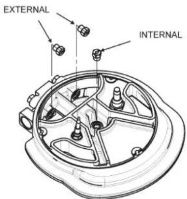
injectors suited to the type of gas in question. To do this, fi rst remove th burner tops using a an appropriate tool. Now unscrew injector (see fi g. 16) and fi t a injector corresponding to the utilized type of gas in its place.
It is advisable to strongly tighten the injector in place.
To access the injector, (fi g. 18 and fi g. 19).
After the injectors have been replaced, the burners must be regulated as explained in paragraphs 9. The technician must reset any seals on the regulating or pre-regulating devices. The envelope with the injectors and the labels can be included in the kit, or at disposal to the authorized customer Service Centre. For the sake of convenience, the nominal rate table also lists the heat inputs of the burners, the diameter of the injectors and the working pressures of the various types of gas.
TAPS LUBRIFICATION Should a tap being blocked, do
not force and ask for Technical Assistance.
WARNING: MAINTENANCE MUST ONLY BE PERFORMED BY AUTHORISED PERSONS.
In case of failure or cut in the cable, please move away from the cable and do not touch it. Moreover the device must be unplugged and not switched on. Call the nearest authorized service center to fix the problem.
| BURNERS | GAS | NORMAL PRESSURE | NORMAL RATE | INJECTOR DIAMETER | NOMINAL HEAT INPUT (W) | ||||
| N° | DESCRIPTION | mbar | gr/h | l/h | 1/100 mm | Min. | Max. | EEgasburner** | |
| 1 | DUAL total | G30 - BUTANE | 28 - 30 | 436 | 2x80B+46B | 3500 | 6000 | 56,4% | |
| G31 - PROPANE | 37 | 429 | 2x80B+46B | 3500 | 6000 | ||||
| G20 - NATURAL | 20 | 571 | 2x125A+71A | 3500 | 6000 | ||||
| DUAL central | G30 - BUTANE | 28 - 30 | 58 | 46B | 800 | ||||
| G31 - PROPANE | 37 | 57 | 46B | 800 | |||||
| G20 - NATURAL | 20 | 76 | 71A | 800 | |||||
**In accordance with Regulation No. 66/2014 EU measures for the implementation of Directive 2009/125/EC, the performance (EEgas burner) was calculated according to EN 30-2-1 last review with the G20.
TYPE AND SECTION OF THE POWER CABLES
| Typo of cable | Monophase power supply220 V ~230 V ~220 - 240 V ~230 - 240 V ~ | Monophase power supply(2 elements)220 - 230 V ~220 - 240 V ~ | Monophase power supply(4 elements)220 - 230 V ~220 - 240 V ~ | ||
| gas | B | H05 RR-FH05 RN-FH07 RN-F | 3 × 0.75 mm^2 | ||
| inducción | A | H05 RR-F | 3 × 1.5 mm^2 | ||
| H05 V2V2-F | 5 × 1.5 mm^2 |
ATTENTION!!!
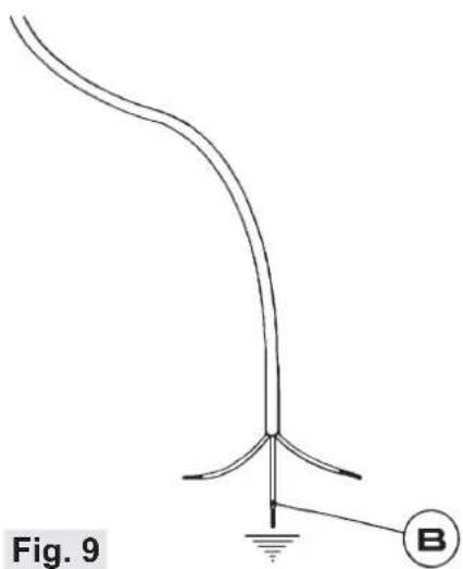
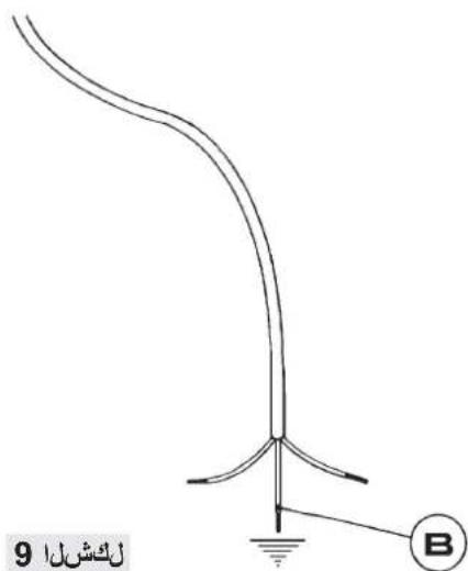
If the power supply cable is replaced, the installer should leave the ground wire (B) longer than the phase conductors (fig. 9) and comply with the recommendations given in paragraph 8.
POWER RATINGS OF THE ELECTRICAL COMPONENTS
| DENOMINATIONS | ∅ (cm) | ∅ pot recommended (minimum in cm.) | POWER (W) | *ECelectric cookingWh/kg |
| Element heating induction | 15,0 | 10 | 1200/1600 | 182,1 |
| Element heating induction | 21,5 | 13 | 2100/3000 | 178,7 |
| Heating element ind. flex 22.8X20.0 cm | 22,8 x 20,0 | 18 | 1750/2000 W | 194,6 |
| Heating element ind. flex 22.8X20.0 cm | 22,8 x 20,0 | 18 | 1750/2000 W | 194,6 |
*EC _electric cooking : energetic consumption calculated per kg in accordance with Regulation (EU) 66/2014.
INSTALLATION
Installation with cutlery drawer
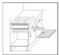
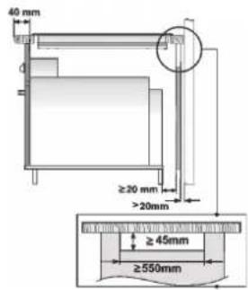
If you wish to install furniture or a cutlery drawer under the hob, a separation board must be fitted between the two. Accidental contact with the hot surface of the device's housing is thus prevented. The board must be fitted 18 mm beneath the under part of the stovetop, oven housing, if installed in the same unit.
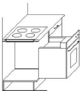
Put the oven on top
See figure 10 for cutting table dimensions and ventilation openings are required!
ELECTRICAL CONNECTION
Before you connect the stovetop to the mains, check that the voltage and frequency match those specified on the stovetop nameplate, which is underneath it, and on the Guarantee Sheet, or if applicable on the technical data sheet, which you must keep together with this manual throughout the product's service life.
Ensure that the inlet cable does not come into contact with the induction top housing or the oven housing, if it is installed in the same unit.
Warning:
The electrical connection must be properly grounded, following current legislation, otherwise the induction hob may malfunction.
Unusually high power surges can damage the control system (like with any electrical appliance).
It is advised to refrain from using the induction hob during the pyrolytic cleaning function in the case of pyrolytic ovens, due to the high temperature that this type of device attains.
Only the official technical service can handle or repair the appliance, including
replacement of the power cable.
Before disconnecting the hob form the mains, we recommend switching off the cutoff switch and waiting for approximately 23 seconds before disconnecting from the mains. This time is required to allow for the complete discharge of the electronic circuitry and thus preclude the possibility of electric shock from the cable terminals.

Keep the Guarantee Certificate or the technical data sheet together with the instructions manual throughout the product's service life. These contain important technical information.
ABOUT INDUCTION
Advantages
With an induction hob, the heat is transmitted directly to the pan.
This has a number of advantages:
-Saves time.
-Saves energy.
-Easy to clean as if the food comes into contact with the glass plate, it does not burn easily.
-Improved energy control. The energy is transferred to the pan as soon as the power controls are pressed. In addition, as soon as the pan is removed from the cooking zone, the power supply stops. It is not necessary to switch the power off first.
Pans
Only ferromagnetic pans are suitable for use with an induction hob.
There are several types:
-cast iron, enameled steel, and stainless steel pans specifi cally for use with induction hobs.
We do not recommend the use of diffuser plates or materials such as fine steel, aluminum, glass, copper, or clay.
the material and the ferromagnetic diameter of the base of the pan. Therefore it is essential to use the cooking zone that best matches the diameter of the base of the pan to be used.
If the pan is not detected on the selected cooking zone, try using the next smallest zone.
When the Flex Zone is used as a single cooking zone, larger pans suitable for this type of zone can be used (see fig. 23).
Fig. 23
natural_image
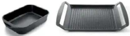
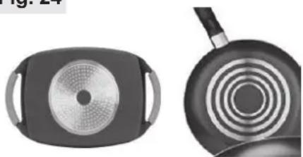
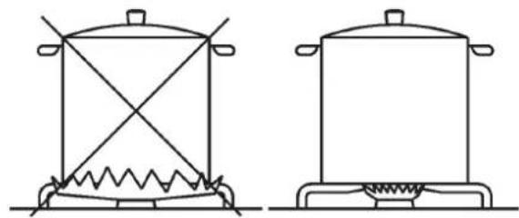
Two black plastic kitchen utensils: a rectangular bowl and a rectangular grater with side handles (no text or symbols visible)Some pans without a complete ferromagnetic base are sold as suitable for induction (see fig. 24). In these pans, only the ferromagnetic base is heated. Consequently the heat is not evenly distributed across the base of the pan. This may mean that the non-ferromagnetic part of the base of the pan does not reach the right cooking temperature.
Fig. 24
natural_image
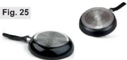
Two views of a cooking pan with a circular vent and lid, shown from top and side (no text or symbols visible)Other pans, with aluminum inserts in the base have a smaller area of ferromagnetic material (see fig. 25). In this case, it may be difficult or even impossible to detect the pan. In addition, the power supplied may be lower and, consequently, the pan will not heat up correctly.
natural_image
Two black frying panes with metallic surfaces, one open and one closed, labeled Fig. 25 (no text on the panes themselves)Influence of the base of the pans
Each cooking zone has a minimum The type of base used on the pan detection time. This depends on pan may affect the uniformity
and results of the cooking. Pans with a stainless steel “sandwich” base use materials that assist the uniform distribution and diffusion of the heat, resulting in savings in time and energy
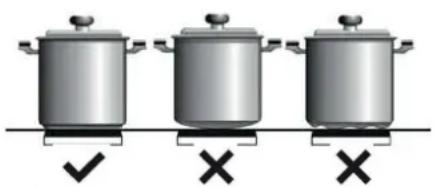
The base of the pan must be completely flat, thus ensuring a uniform power supply (see fig. 26).
Fig. 26
natural_image
Three identical cooking pots with checkmark and cross symbols below (no text or labels)⚠️ Never heat empty pans, or use pans with a thin base, as these may heat up quickly without allowing time for the automatic disconnection function of the cooker to come into operation.

IMPORTANT RECOMMENDATIONS:
Use vessels with the same base diameter as that of the cooking zone.
In the cooking zones closest to the control panel, always keep the vessels within the cooking marks indicated on the glass surface and use vessels of the same or smaller diameter to these. This will help to prevent overheating in the control zone.
Use the rear cooking zones for intensive use of the appliance. This will help to prevent overheating of the control panel.
Do not allow the vessels to invade the control panel zone, especially during cooking.
Use and Maintenance
USER INSTRUCTIONS OF THE TOUCH CONTROL
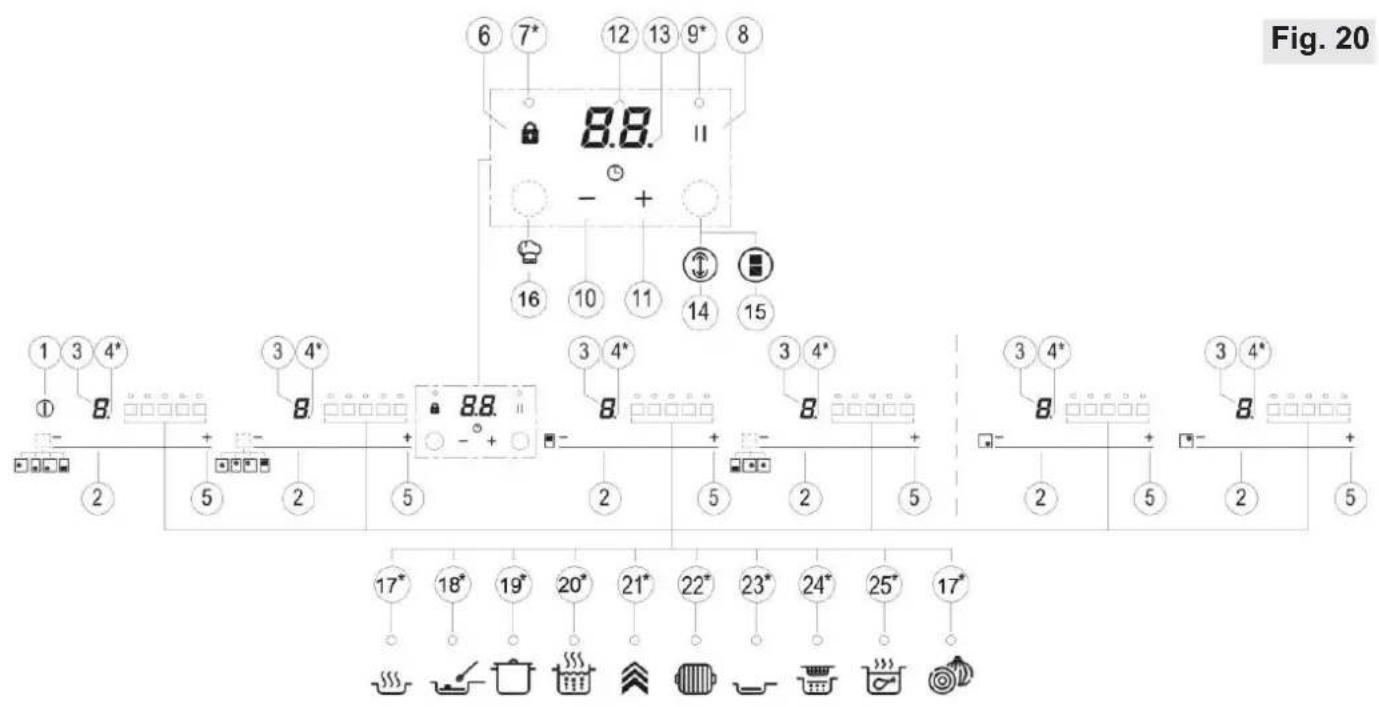
HANDLING ELEMENTS (fi g. 20)
1 General on/off sensor.
2 Cursor slider for controlling power.
9 Pilot indicator light "Stop & Go" function* Only visible while running. activated*.
3 Power and/or residual heat indicator*.
4 Decimal dot of power and/ of residual heat indicator.
5 Direct access to "Power" function.
6 Activation sensor for "Block" function.
7 Pilot indicator light "Block" function activated*.
8 Activation sensor for "Stop&Go" function.
10 "Minus" sensor for timer.
11 "Plus" sensor for timer.
12 Timer indicator.
13 Decimal dot of the timer.*
14 Activation sensor for "Synchro" function; (depending on model).
15 Activation sensor for "Flex Zone" function; (depending on model).
16 Activation sensor for "Chef" functions; (depending on model).
17 Pilot indicator light "Keep Warm" function activated*; (depending on model).
18 Pilot indicator light" Melting" function activated*; (depending on model).
19 Pilot indicator light "Simmering" function activated*; (depending on model).
20 Pilot indicator light "Quick Boiling" function activated*; (depending on model).
21 Pilot indicator light "Slide Cooking" function activated*; (depending on model).
22 Pilot indicator light "Grilling" function activated*; (depending on model).
23 Pilot indicator light "Pan Frying" function activated*; (depending on model).
24 Pilot indicator light "Deep Frying" function activated*; (depending on model).
25 Pilot indicator light "Conf i t" function activated*; (depending on model).
26 Pilot indicator light "Poaching" function activated*; (depending on model).
The manoeuvres are done by means of the touch keys. You do not need to exert force on the desired touch key, you only need to touch it with your fi ngertip to activate the required function
Each action is verified by a beep. Use the cursor slider (2) to adjust power levels (0 - 9) by sliding your finger over it. Sliding towards the right increases the value, whereas sliding towards the left decreases it.
It's also possible to directly select a power level by placing your fi nger directly on a desired point of the cursor slider (2)
In order to select a plate on these models, directly touch the cursor slider (2).
SWITCHING ON THE DEVICE
1 Touch the On touch key① (1) for at least one second. The touch control will become active, a beep will be heard and the indicators (3) to will light up displaying a “-”. If any cooking area is hot, the related indicator will fl ash an H. If you do not take any action in the next 10 seconds the touch control will switch off automatically.
When the touch control is activated, you can disconnect it at any time by touching the touch button ① (1), even if it has been locked (lock function activated). The touch button ① (1) always has priority to disconnect the touch control.
ACTIVATING PLATES
detected or the pan is not suitable
will display "OF".
Once the Touch Control is activated with sensor①(1), any plate can be turned on by following these steps:
1 Slide the finger or touch in any position of one of the cursors "slider" (2). The zone has been selected and simultaneously the power level will be set between 0 and 9. That power value will be shown on the corresponding power indicator and its decimal dot (4) will keep light up during 10 seconds.
2 Use the cursor slider (2) to choose a new cooking level between 0 and 9.
As long as the plate is selected, in other words, with the decimal (4) dot light up, its power level can be modified.
TURNING OFF A PLATE
Using the touch slider key (2) lower the power to level 0. The hotplate will switch off.
When a hot plate is switched off an H will appear in its power indicator (3), if the glass surface of the related cooking area is hot and there is a risk of burns. When the temperature drops, the indicator (3) switches off (if the hob is disconnected), or otherwise a “-” will light up if the hob is still connected.
TURNING ALL PLATES OFF
All plates can be simultaneously disconnected by using the general on/off sensor (1). All plate indicators (3) will turn off. If the heating zone turned off is hot, its indicator shows an H.
PAN DETECTOR
Induction cooking zones have a built-in pan detector. This way, the plate will stop working if there is no pan present or if the pan is not suitable.
The power indicator (3) will show a symbol to designate “there is no pan” if, while the zone is on, no pan is
If a pan is taken off the zone while it is running, the plate will automatically stop supplying energy and it will show the symbol for "there is no pan". When a pan is once again placed on the cooking zone, energy supply will resume at the same power level previously selected.
If a pan is taken off the zone while it is running, the plate will automatically stop supplying energy and it will show the symbol for "there is no pan". When a pan is once again placed on the cooking zone, energy supply will resume at the same power level previously selected.
When fi nished, turn off the cooking zone by using the touch controls. Otherwise an undesired operation could occur if a pan is accidentally placed on the cooking zone during the three min u t e s. Avo i d pos s i b le accidents!
BLOCK FUNCTION
With the Block Function, you can block the other sensors, except for the on/off sensor①(1), in order to avoid undesired operations. This function is useful as a childproof safety.
To activate this function, touch sensor (6) for at least one second. Once you have done so, the pilot (7) turns on indicating that the control panel is blocked. To deactivate the function, simply touch sensor (6) again.
If the on/off sensor ① (1) is used to turn off the appliance while the block function is activated, it won't be possible to turn the cooktop on again until it unblocks.
When the hob is on, if one presses the touch key + (11) and the locking touch key 🔒 (6) simultaneously for three seconds, the beep that accompanies each action will be deactivated. The time indicator (12)
This deactivation will not be applied to all the functions, as for example the beep for on/off, the ending of the timer or the locking/unlocking of the touch keys always remain activated.
To once again activate all the beeps that accompany each action, again simultaneously press the touch key (11) and the locking touch key (6) for three seconds. The time indicator (12) will display "On".
STOP&GO FUNCTION
This function puts the cooking process on pause. The timer will also be paused if it is activated.
Activating the Stop function.
Touch the Stop sensor (8) for one second. The pilot (9) lights up and the power indicators will show the symbol to indicate cooking has been paused.
Deactivating the Stop function
Touch Stop&Go sensor (8) again. The pilot (9) turns off and cooking resumes under the same power and timer settings that were established before the pause.
POWER FUNCTION
This function supplies “extra” power to the plate, above the nominal value. Said power depends on the size of the plate, with the possibility of reaching the maximum value permitted by the generator.
1 Slide the finger above the corresponding cursor slider (2) until the power indicator (3) shows "9" and keep the finger pressed for one second, or touch directly on "P" and keep pressed the finger for one second.
2 The power level indicator (3) will show the symbol, and the plate will start to supply extra power. The Power function has a maximum duration specified in Table 1. After this time, the power level will automatically adjust to 9. A beep sounds.
On activating the Power function in one hotplate, it is possible that the performance of some of the others may be affected, reducing its power to a lower level, in which case this will be displayed on its indicator (3). Deactivation of Power Function, before its working time passes, can be done either by means of touching cursor "slider" modifying its power level or repeating step 3.
TIMER FUNCTION (countdown clock)
This function facilitates cooking given that you don't have to be present: You can set a timer for a plate, and it will turn off once the desired time is up.
For these models, you can simultaneously program each plate for durations ranging from 1 to 99 minutes.
Setting a timer on a plate.
Once the power level is set on the desired zone, and while the decimal dot of the zone keeps on, the zone will be able to be timed.
To that end:
1 Touch sensor—(10) or (11). Timer Indicator (12) will show "00" and corresponding zone indicator (3) will show the symbol ℓ blinking alternately with its current power level.
2 Immediately afterwards set a cooking time between 1 and 99 minutes, using the sensors — (10) ó +11). With the first one the value will start at 60, whereas with the second it will start at 01. By keeping sensors — (10) ó + (11) pressed, the value will be restored to 00. When there is less than one minute left, the clock will begin to count down in seconds.
- When the timer indicator (12) stops flashing, it will start to count down the time automatically. The indicator (3) relating to the timed hotplate will alternately display the selected power level and the symbol E.
Once the selected cooking time has
elapsed, the heating zone being timed is turned off and the clock emits a
series of beeps for several seconds. To turn off the audible signal, touch any sensor. The timer indicator (12) will display a flashing 00 beside of the decimal dot (4) of the selected zone. If the heating zone turned off is hot, its power indicator (3) will display alternately the H symbol and a “-”.
If you wish to time another hotplate at the same time, repeat steps 1 to 3.
If one or more zones are already timed, the timer indicator (12) will show by default the shortest remaining time to finish, showing a "t" on the related zone. Rest of timed zones will show on their corresponding indicator zones the decimal dot blinking. When cursor "slider" of another timed zone is pressed, the timer will show the remaining time of that zone for a few seconds and its indicator will show its power level and the "t" alternately.
Changing the programmed time.
For modifying programmed time, cursor "slider" (2) of timed zone has to be pressed. Then it will be possible to read and modify the time.
Through sensors—(10) and+ (11), you can modify the programmed time.
Disconnecting the clock
If you wish to stop the clock before the programmed time is up, this can be done at any time by simply adjusting its value to ‘--’.
1 Select the desired plate.
2 Adjust the value of the clock to "00" by using the sensor—(10). The clock is cancelled. This can also be done more quickly by pushing the "sensors" (10) and + (11) at the same time.
POWER MANAGEMENT FUNCTION
Some models are equipped with a power limiting function (Power Management). This function allows the total power generated by the hob to be set to different values selected by the user. To do this, for the first minute after having connected the hob to the power supply, it is possible to access the power limiting menu.
1 Press the + (11) touch key for three seconds. The letter PL will appear on the timer indicator (12)
2 Press the locking touch key (6). The different power values to which the hob can be limited will appear and these can be changed using the + (11) and - (10) sensors.
3 Once the value has been selected, once again press the locking touch key 🔒 (6). The hob will be limited to the chosen power value.
If you want to change the value again, you must unplug the hob and plug it in again after a few seconds. Thus you will again be able to enter the power limiting menu.
Every time the power level of a hotplate is changed, the power limiter will calculate the total power the hob is generating. If you have reached the total power limit, the touch control will not allow you to increase the power level of that hotplate. The hob will beep and the power indicator (3) will blink at the level that cannot be exceeded. If you wish to exceed that value, you must lower the power of the other hotplates. Sometimes it will not be enough to lower another by a single level as this depends on the power of each hotplate and the level it is set at. It is possible that to raise the level of a large hotplate that of several smaller ones must be turned down.
If you use the quick switch-on at maximum power function and the said value is above the value set by the limit, the hotplate will be set to the maximum possible level. The hob will beep and the said power value will blink twice on the
indicator (3).
SPECIAL FUNCTIONS: CHEF
These functions have pre-allocated power levels to make cooking easier, obtaining excellent results as the temperature of the pan is controlled continuously by sensors. When the target temperature for the function has been reached, it is automatically maintained without needing to change the power level.
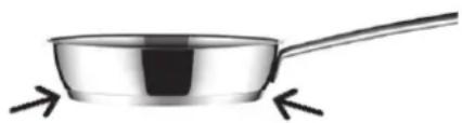
The Chef functions operate correctly with pans with the same ferromagnetic area on the base of the pan as the area of the cooking zone. In addition, for high temperature functions (above 100°C), pans must have a flat, even base (preferably “sandwich” type) as shown in figure 27.
Fig. 27
natural_image
Illustration of a stainless steel cooking pan with a handle and two arrows pointing to it (no text or symbols)To ensure the correct operation of these functions, it is important that the pan and the cooking zone are not hot at the start of the process.
Further information about suitable pans (saucepans, frying pans, grills, etc.) is given on the Teka web page.
The Touch Control has special features that help the user to cook through the CHEF sensor (16). These functions are available depending on the model. To activate a special feature on a zone:
1 First it should be selected; and then, the decimal point (4) will be active on the power indicator (3).
2 Now click on the CHEF sensor
(16). The sequentially successive presses will go over all the CHEF functions available in each zone one by one. These functions will show the activation with the corresponding leds (16), (17), (18), (19), (20), (21), (22) and (23).
You can override the function at any time by turning off the plate, by changing the power level or by choosing a different special function.
SIMMERING FUNCTION
This feature allows you to keep
If you want to cancel a special active function at any time, you should touch the "slider" cursor sensor (2) of the related zone to select it. The decimal point (4) of the power indicator (3) will light up. Then, touch again the "slider" (2) cursor to set a new power level or to power off the zone, or you can choose a different special function touching again on the CHEF sensor (15).
KEEP WARM FUNCTION
This function automatically sets an appropriate power level to keep the cooked food hot. To activate it, select the plate, and press on the CHEF sensor (16) until the led (17) located on the icon lights up. Once the function is activated, the symbol will appear on the power indicator (3). You can override the function at any time by turning off the plate, by changing the power level or by choosing a different special function.
MELTING FUNCTION
This function maintains a low temperature in the cooking zone. Ideal for defrosting food or for slowly melting other food types as chocolate, butter, etc.
To activate it, select the plate, and press on the CHEF sensor (16) until the led (18) located on the icon lights up. Once the function is activated, the symbol will appear on the power indicator (3).
After the food is boiled, enable the plate by selecting it, and press the CHEF sensor 🎨 (16) until the led (19) located on the icon 📋 lights up. Once the function is activated, the symbol ⚠ will appear on the power indicator (3).
You can override the function at any time by turning off the plate, by changing the power level or by choosing a different special function.
QUICK BOILING FUNCTION (depending on the model)
This function enables the automatic boiling control, which is a great help for cooking pasta, rice, eggs, boil some food, etc. It is available only in zones where the symbol appears.
Conditions of the container
For a proper operation of the Quick Boiling function, you need to use a container that meets the following preconditions:
- Bottom size as close as possible to the diameter of the plate.
- WITHOUT CAP.
- Filled to over half its capacity at room temperature water (never use warmed or hot water).
Failure to comply with these conditions will distort the proper control of boiling.

Fig. 29
WARNING: do not use this feature for a different cooking purpose other than boiling water. Never use oil, it may lead to overheat and generate a flame.
Activation of the function
To activate the function, select the plate, and press the CHEF sensor (16) until the led (20) located on the icon lights up.
Once the feature is activated, the sign R will appear on both the power indicator (3) and the timer indicator (12); a moving segment will appear, indicating that the cooking is under system's control.
When the system detects that it is about to start boiling, a fi rst beep will be heard. Take this opportunity to prepare your food for boiling or baking as desired.
After 30 seconds, a second beep will be heard; if you have not already done so, it's time to pour the food in the pan.
After the second beep, the system will activate the timer and stopwatch for you so that you can control how long the food is to be boiled.
30 seconds after activating the stopwatch, a third beep will sound to warn that from that moment on, the system will decrease the power supplied in order to maintain a gentle and continuous boil. The timer will remain active until the end of cooking.
If desired, you can disable the timer and set a time for the countdown and automatic shutdown of the plate (see section Timer Function).
Deactivation of the function
You can override the function at any time by turning off the plate, by changing the power level or by choosing a different special function.
SLIDE COOKING FUNCTION (depending on the model)
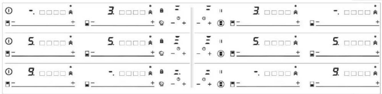
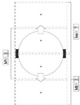
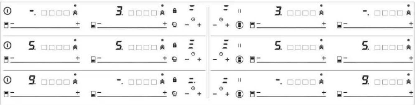
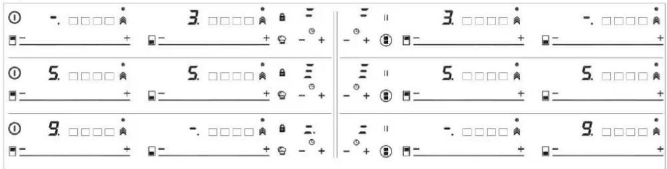
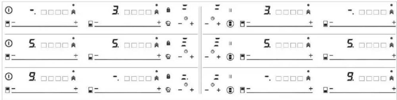
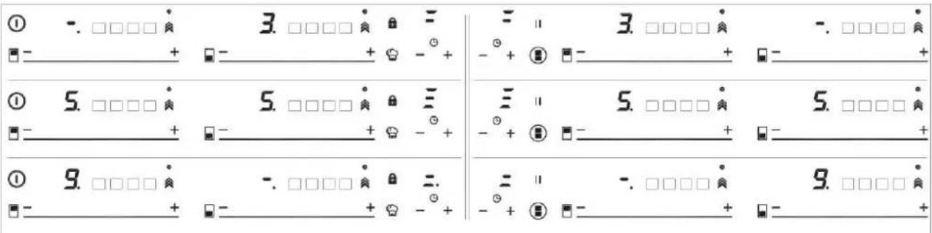
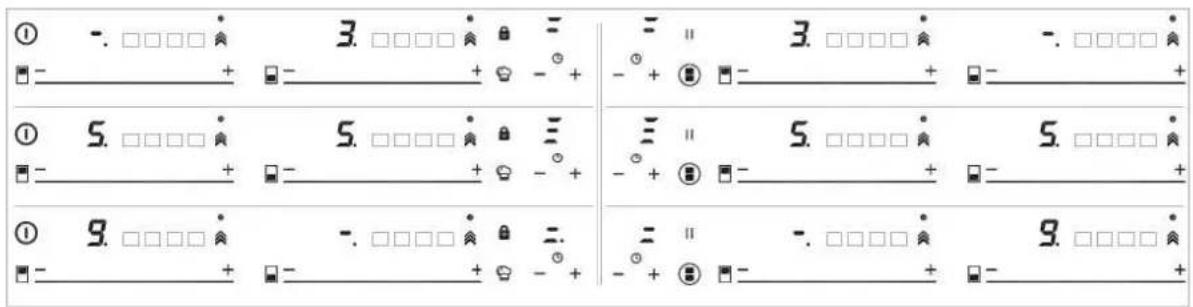
This function allows to divide the fl exible zone into three areas (see fi g. 31) and activates a predefined power configuration. It will allow slide the vessel from one area to another, to cook with the power assigned to each zone.
To activate it, you must first activate the "Flex Zone" function (see section "Flex Zone function").
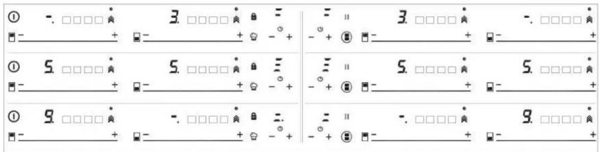
After, press on the CHEF sensor (16), until the leds (21) located on the icon lights up. When doing so, the power indicators (3) will show three segments (see fig. 29) indicating that you can now place the vessel.
Once the vessel is placed, the power level will appear automatically in the power indicators (3): for zone #1, the power level is 3, for zone
2 the power level is 5 and for zone
3 the power level is 9 (see fig. 31 and 30).
To deactivate this function, you must touch the "slider" cursor (2) in the position "0".
Fig. 31
flowchart
graph TD
    A["•"] --> B["•"]
    B --> C["•"]
    C --> D["•"]
    D --> E["•"]
    E --> F["•"]
    F --> G["•"]
    G --> H["•"]
    H --> I["•"]
    I --> J["•"]
    J --> K["•"]
    K --> L["•"]
    L --> M["•"]
    M --> N["•"]
    N --> O["•"]
    O --> P["•"]
    P --> Q["•"]
    Q --> R["•"]
    R --> S["•"]
    S --> T["•"]
    T --> U["•"]
    U --> V["•"]
    V --> W["•"]
    W --> X["•"]
    X --> Y["•"]
    Y --> Z["•"]
    Z --> A
    style A fill:#000,stroke:#000,color:#fff
    style B fill:#000,stroke:#000,color:#fff
    style C fill:#000,stroke:#000,color:#fff
    style D fill:#000,stroke:#000,color:#fff
    style E fill:#000,stroke:#000,color:#fff
    style F fill:#000,stroke:#000,color:#fff
    style G fill:#000,stroke:#000,color:#fff
    style H fill:#000,stroke:#000,color:#fff
    style I fill:#000,stroke:#000,color:#fff
    style J fill:#000,stroke:#000,color:#fff
    style K fill:#000,stroke:#000,color:#fff
    style L fill:#000,stroke:#000,color:#fff
    style M fill:#000,stroke:#000,color:#fff
    style N fill:#000,stroke:#000,color:#fff
    style O fill:#000,stroke:#000,color:#fff
    style P fill:#000,stroke:#000,color:#fff
    style Q fill:#000,stroke:#000,color:#fff
    style R fill:#000,stroke:#000,color:#fff
    style S fill:#000,stroke:#000,color:#fff
    style T fill:#000,stroke:#000,color:#fff
    style U fill:#000,stroke:#000,color:#fff
    style V fill:#000,stroke:#000,color:#fff
    style W fill:#000,stroke:#000,color:#fff
    style X fill:#000,stroke:#000,color:#fff
    style Y fill:#000,stroke:#000,color:#fff
    style Z fill:#000,stroke:#000,color:#fff
GRILLING FUNCTION
This function sets an automatic power control suitable for cooking on the grill.
To activate it, select the plate, and press on the CHEF sensor (16), until the led (22) located on the icon lights up. Once the function is activated, on the power indicator (3) a moving segment will appear indicating that the cooking is in the preheating phase of the vessel. Once this phase is finished, the sign R will appear on the power indicator (3) and a beep will be heard, indicating to the user that he must add the food.
You can override the function at any time by turning off the plate by changing the power level or by choosing a different special function.
PAN FRYING FUNCTION
This function sets an automatic power control suitable for frying with little oil or sautéing.
To activate it, select the plate, and press on the CHEF sensor (16), until the led (23) located on the icon lights up. Once the function is activated, on the power indicator (3) a moving segment will appear indicating that the cooking is in the preheating phase of the vessel. Once this phase is finished, the sign R will appear on the power indicator (3) and a beep will be heard, indicating to the user that he must add the food.
You can override the function at any time by turning off the plate by changing the power level or by choosing a different special function.
FUNCTION DEEP FRYING
This function sets an automatic power control suitable for frying with plenty of oil.
To activate it, select the plate, and press on the CHEF sensor (16), until the led (24) located on the icon lights up. Once the function is activated, on the power indicator (3) a moving segment will appear indicating that the cooking is in the preheating phase of the vessel. Once this phase is finished, the sign will appear on the power indicator (3) and a beep will be heard, indicating to the user that he must add the food.
You can override the function at any time by turning off the plate by changing the power level or by choosing a different special function.
CONFIT FUNCTION
This function sets an automatic power control suitable for confi t.
To activate it, select the plate, and press on the CHEF sensor(16), until the led (25) located on the icon lights up. Once the function is activated, on the power indicator (3) a moving segment will appear indicating that the cooking is in the preheating phase of the vessel. Once this phase is finished, the sign R will appear on the power indicator (3) and a beep will be heard, indicating to the user that he must be add the food. You can override the function at any time by turning off the plate by changing the power level or by choosing a different special function.
POACHING FUNCTION
This function sets an automatic power control suitable for frying food at medium temperature. Ideal for frying potatoes, in the preparation of the Spanish omelette. To activate it, select the hob, and successively press the CHEF sensor 📋 (16), until the led (26) above the icon 🔒 lights up. Once the function is activated, a moving segment will appear on the power indicator (3), indicating that the system is in the preheating phase of the container. Once this phase is finished, a will appear on the power indicator (3) and an acoustic signal will sound indicating that the user must add food. You can override the function at any time by turning off the hob, modifying the power level, or choosing a different special function.
FLEX ZONE FUNCTION
Through this function, it is possible to enable two cooking zones work together, and to select a power level and to activate the timer function for both zones.
To activate this function, press the sensor (15). By doing so, the decimal points (4) of the linked plates will light up and the value "0" will be shown on their power indicators (3). The clock timer indicator (12) will show three segments indicating the activated zones. In case your model has several zones with "Flex Zone", you can select the desired option by pressing the sensor (15) before assigning the power to the chosen zone. You will have a few seconds to perform the next operation; otherwise, the function will be disabled automatically (see fig 28).
After the “Flex Zone” is selected, you can assign the power by touching any of the “sliders” cursors (2) of one of the linked zone. The power level and its variations are displayed simultaneously on the power indicators (3) of both zones.
To disable this feature, you should touch the sensor ■ (15) again. Also, when the function is disabled, the levels of powers and functions assigned to the related zones are cleared.
SYNCHRO FUNCTION (depending on the model)
Through this function, it is possible to achieve that two cooking zones -indicated in the printing screen as "Synchro" work together and to select a power level and to activate the timer function for both zones
Press the sensor ⏻(14) to active this function. By doing so, the decimal points (4) of the linked plates will light up and the value "0" will blink on their power indicators (3). The detection of the container will take place throughout the linked zone. You will have a few seconds to perform the next operation; otherwise, the function will be disabled automatically. To disable this feature, you should touch the sensor ⏻(14) again. Also, when the function is disabled, the levels of powers and functions assigned to the related zones will be cleared.
SAFETY SWITCH OFF FUNCTION
If due to an error one or several heating zones do not switch off, the appliance will be automatically disconnected after a set amount of time (see table 1).
Table 1
| Selected power level | MAXIMUN OPERATING TIME (in hours) |
| 0 | 0 |
| 1 | 8 |
| 2 | 8 |
| 3 | 5 |
| 4 | 4 |
| 5 | 4 |
| 6 | 3 |
| 7 | 2 |
| 8 | 2 |
| 9 | 1 |
| P | 10 or 5 minutes, readjusts to level 9 (depending on model) |
When the “safety switch off” function has been triggered, a 0is displayed if the glass surface temperature is not dangerous for the user or an H if there is a burn risk.
Keep the control panel of the heating areas clean and dry at all times.
In the event of operating problems or incidents not mentioned in this manual, disconnect the appliance and contact the technical service.
SUGGESTIONS AND RECOMMENDATIONS
* Use pots or pans with thick, comple-tely fl at bottoms.
* Do not slide pots and pans over the glass because they could scratch it.
* Although the glass can take knocks from large pots and pans without sharp edges, try not to knock it.
* To avoid damaging the ceramic glass surface, do not drag pots and pans over the glass and keep the undersides of them clean and in good condition.
* Recommended diameters of the pot bottom (see "Technical Data Sheet" supplied with the product).
Try not to spill sugar or products containing sugar on the
glass as while the surface is hot these could damage it.
CLEANING AND MAINTENANCE
To keep the appliance in good condition, clean it using suitable products and implements once it has cooled down. This will make the job easier and avoid the build-up of dirt. Never use harsh cleaning products or tools that could scratch the surface, or steam-operated equipment.
Light dirt not stuck to the surface can be cleaned using a damp cloth and a gentle detergent or warm soapy water. However, for deeper stains or grease use a special cleaner for ceramic hot plates and follow the instructions on the bottle. Dirt that is firmly stuck due to being burned repeatedly can be removed using a scraper with a blade.
Slight tinges of colour are caused by pots and pans with dry grease residue underneath or due to grease between the glass and the pot during cooking. These can be removed using a nickel scourer with water or a special cleaner for ceramic hot plates. Plastic objects, sugar or food containing a lot of sugar that have melted onto the surface must be removed immediately using a scraper.
Metallic sheens are caused by dragging metal pots and pans over the glass. These can be removed by cleaning thoroughly using a special cleaner for ceramic glass hot plates, although you may need to repeat the cleaning process several times.
Warning:
A pot or pan may become stuck to the glass due to a product having melted between them. Do not try to lift the pot while the heating zone is cold! This could * break the glass.
Do not step on the glass or lean on it as it could break and cau-se injury. Do not use the glass as a surface for placing objects.
The manufacturer reserves the right to make changes to its manuals that it deems necessary or useful,
without affecting the product's essen-tial features.
ENVIRONMENTAL CONSIDERATIONS

The symbol □ on the product or its packaging means that this product cannot be treated like ordinary household waste. This product must be taken to a recycling collection point for electrical and electronic appliances. By ensuring that this product is disposed of correctly, you will avoid harming the environment and public health, which could happen if this product is not handled properly. For more detailed information about recycling this product, please contact your local authority, household waste service or the store where you purchased the product. The packaging materials used are environmentally friendly and can be recycled completely. Plastic components are marked >PE<, >LD<, EPS<, etc. Dispose of packaging materials, like household waste, in your local container.
Fulfillment with Energy Efficiency of the appliance:
- Appliance has been tested according to standard EN 60350-2 and the obtained value, in Wh/kg, is available in the appliance's rating plate.
Following advices will help you to save energy anytime you cook:
* Use the correct lid for each pot whenever is possible. Cooking without lid uses more energy.
* Use pans with flat bases and appropriate base diameters in order to match size of the cooking zone. Pan manufacturers usually provide top diameter of the pot that is always larger than base diameter.
* When water is used for cooking, use little quantities in order to preserve vitamins and minerals of vegetables and set the minimum power level that allows maintaining the cooking. High power level is unnecessary and a waste of energy.
* Use small pots with small quantities of food.
IF SOMETHING DOES NOT WORK
Before calling the technical service, perform the verifi cations described below.
The appliance does not work:
Ensure that the power cable is plugged in.
The induction zones do not produce heat:
The container is not appropriate (it does not have a ferromagnetic bottom or is too small). Check that the bottom of the container attracts a magnet, or use a larger container.
A humming is heard when starting to cook in the induction zones:
With containers which are not very thick or not of one piece, the hummir results from the transmission of energy directly to the bottom of the container. The humming is not a defect, but if you wish to avoid it anyway, reduce the power level slightly or use a container with a thicker bottom, and/or of one piece.
The touch control does not light up or, despite lighting, does not respond:
No heating zone has been selected. Be sure to select a heating zone before operating it.
There is humidity on the sensors, and/or your fingers are wet. Keep the touch control surface and/or your fingers clean and dry. The locking function is activated. Unlock the controls.
The sound of a fan is heard while cooking, which continues even after cooking has ended:
The induction zones have a fan to keep the electronics cool. This only operates when the electronic circuits get hot. It stops again when the circuits cool whether the hob is turned on or not.
The symbol will appear on the power indicator of a hotplate:
The induction system does not find a pot or pan on a hotplate or it is of an unsuited type.
The hotplate will switch off and the message C81 or C82 will appear on the indicators:
Excessive temperature in the electronics or on the glass. Wait for a while for the electronics to cool down or remove the pot or pan so that the glass can cool.
C85 appears on the indicator of one of the hotplates:
The pot or pan used is of an unsuited type. Switch off the hob, switch it on again and try with another pot or pan.
The appliance switches off and the message C90 appears on the power indicators (3):
The touch control detects on/off (1) sensor is covered and doesn't allow switching on the cooktop. Remove the possible objects or liquids keeping the touch control surface, clean and dry until the message disappears.
The appliance switches off and the message C91 appears on the power indicators (3):
The touch control detects Stop&Go sensor (6) is covered and doesn't allow to handle the cooktop. Remove the possible objects or liquids keeping the touch control surface, clean and dry, then press twice Stop&Go (6) sensor for removing the message and return to normal operation.
KIG9850.0SRKIG6850.0SR
EMPLACEMENT ET EVACUATION DES PRODUITS DE LA COMBUSTION
Remonter correctement les diff érents composants.
REPLACEMENT DES BUSES

Fig. 29
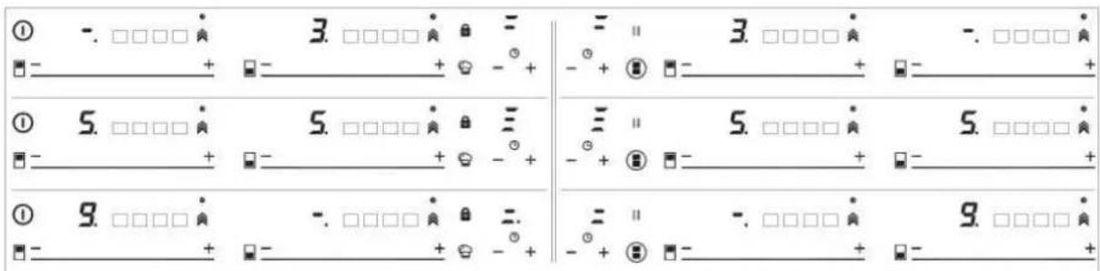
Fig. 30
SUGGESTIONS ET RECOMMANDATIONS
natural_image
Close-up of a black frying pan with concentric circular patterns (no text or symbols visible)natural_image
Illustration of a stainless steel cooking pan with a handle and two arrows pointing to it (no text or symbols)Eik. 30
natural_image
Simple geometric diagram showing a circle with a small circle inside, no text or symbols present.MIN INT


MIN EXT MAX INT

MAX INT
QUEIMADOR DUAL
natural_image
Two black plastic kitchen trays, one rectangular and one rectangular, with no visible text or symbols.natural_image
Two black cooking panes with visible grilles and side handles, placed side by side on white background (no text or symbols)natural_image
Three identical cooking pots with checkmark and cross symbols below (no text or labels)
Eik. 30
natural_image
Illustration of a stainless steel cooking pan with a handle and two arrows pointing to it (no text or symbols)KIG9850.0SRKIG6850.0SR
natural_image
Three identical cooking pots with checkmark and cross symbols below (no text or labels)
Şekil. 30
natural_image
Illustration of a stainless steel cooking pan with arrows pointing to the side (no text or symbols)KIG9850.0SRKIG6850.0SR

ARZĂTOR „DUAL”
natural_image
Two kitchen utensils: a black pan with a circular fan and a black pan with concentric rings (no text or symbols visible)
natural_image
Illustration of a stainless steel cooking pan with a handle and two arrows pointing to it (no text or symbols)Fig. 30
FUNCTIA „ KEEP WARM (PÄSTRARE LA CALD)
KIG9850.0SRKIG6850.0SR
Attention: this appliance has been manufactured for domestic use only and it employment by private person.
DUAL
obr. 22
Burners ∅ pans cm.
DUAL total 22 ÷ 30
DUAL central 12 ÷ 16
HOŘÁK „DUAL“
natural_image
Close-up of a black frying pan with concentric circular patterns (no text or symbols visible)natural_image
Two black cooking panes with metallic surfaces, one with a starburst pattern and the other with a perforated lid (no text or symbols visible)natural_image
Three identical cooking pots on a flat surface, each marked with a checkmark and an 'X' symbol below (no text or labels)natural_image
Illustration of a stainless steel cooking pan with a handle and two arrows pointing to it (no text or symbols)Obr. č. 30
atd.
KIG9850.0SRKIG6850.0SR

natural_image
Simple geometric diagram showing a circle with a small circle inside, no text or symbols present.MIN INT


MIN EXT
MAX INT

MAX INT
HORÁK "DUÁL"
natural_image
Close-up of a black frying pan with concentric circular patterns (no text or symbols visible)natural_image
Two black cooking panes with perforated surfaces, one emitting smoke or vapor (no text or symbols visible)Vplyv dna panvic

natural_image
Illustration of a stainless steel cooking pan with a handle and two arrows pointing to it (no text or symbols)Obr. 30
KIG9850.0SRKIG6850.0SR
PALNIK „DUAL”
natural_image
Three identical cooking pots with checkmark and cross symbols below (no text or labels)natural_image
Illustration of a stainless steel cooking pan with a handle and two arrows pointing to it (no text or symbols)Obr. 30
BRUCIATORE "DUAL"
In case of hotplate glass breakage:
- shut immediately off all burners and any electrical heating element and isolate the appliance from the power supply;
- do not touch the appliance surface;
- do not use the appliance.
ACCENSIONE DEL DISPOSITIVO
natural_image
Illustration of a stainless steel cooking pan with a handle and arrow indicators (no text or symbols)Fig. 30
30 للكشلا
natural_image
Illustration of a stainless steel cooking pan with a handle and two arrows pointing to it (no text or symbols)natural_image
Two black frying panes with metallic surfaces, one closed and one with a perforated lid (no text or symbols visible)natural_image
Three identical cooking pots with checkmark and cross symbols below (no text or labels)KIG9850.0SRKIG6850.0SR
6000 واط قدرة
natural_image
Simple geometric diagram showing a circle with a small circle inside, no text or symbols present.natural_image
Technical line drawing of a gas stove with cooling fans and mounting base (no text or symbols)16 لكشل
18 لكشل

natural_image
Close-up of a hand using a tool to adjust or install a mechanical component on a dark surface (no visible text or symbols)19 لکشلا
natural_image
Line drawing of a kitchen setup with an oven, stove, and built-in cabin (no text or symbols)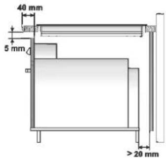
نرف
natural_image
Line drawings of two cooking pots with steamers, no text or symbols presentلکشلا 1


natural_image
Line drawing of a hand using a tool to clean or inspect a circular component (no text or symbols)6 لكشل
7 لکشل 8 لکشل

natural_image
Close-up of a metallic rectangular object with a circular indentation and a labeled point E (no text or symbols on the object itself)5 لكشلا

KIG6850.0SR
KIG9850.0SR
Küppersbusch
- ABCDEFG
- QUEMADOR "DUAL"
- Burners ∅ pans cm.
- DUAL BURNERS
- LIGHTING AND USING THE "DUAL" BURNER
- Stand the pan on the burner before lighting.
- A) - Using the complete burner: starting from the off position • You must first press the knob, simultaneously turning it anticlockwise,
- B) - Using the inner flame only: after lighting the burner and regulating the inner flame to maximum flow capacity and the outer flame to minimum flow capacity as described above, turn the knob anti-clockwise until it clicks once. The inner flame is now at maximum flow capacity while the outer flame is turned off.
- Turning off :
- IMPORTANT WARNINGS FOR THE USER
- IMPORTANT:
- HOT PLATE
- WARNINGS:
- CAUTION:
- TECHNICAL INFORMATION FOR THE INSTALLER
- INSTALLING THE HOT PLATE
- FIXING THE HOT PLATE
- IMPORTANT INSTALLATION Openable window or alternative INSTRUCTIONS
- ROOM VENTILATION
- GAS CONNECTION
- ELECTRICAL CONNECTION
- TAPS
- "Reduced rate" adjustment
- REPLACING THE INJECTORS
- WARNING: MAINTENANCE MUST ONLY BE PERFORMED BY AUTHORISED PERSONS.
- INSTALLATION
- Installation with cutlery drawer
- Put the oven on top
- Warning:
- ABOUT INDUCTION
- Advantages
- Pans
- IMPORTANT RECOMMENDATIONS:
- Use and Maintenance
- USER INSTRUCTIONS OF THE TOUCH CONTROL
- HANDLING ELEMENTS (fi g. 20)
- In order to select a plate on these models, directly touch the cursor slider (2).
- SWITCHING ON THE DEVICE
- ACTIVATING PLATES
- TURNING OFF A PLATE
- TURNING ALL PLATES OFF
- PAN DETECTOR
- BLOCK FUNCTION
- STOP&GO FUNCTION
- Activating the Stop function.
- Deactivating the Stop function
- POWER FUNCTION
- TIMER FUNCTION (countdown clock)
- Setting a timer on a plate.
- Changing the programmed time.
- Disconnecting the clock
- POWER MANAGEMENT FUNCTION
- SPECIAL FUNCTIONS: CHEF
- SIMMERING FUNCTION
- KEEP WARM FUNCTION
- MELTING FUNCTION
- QUICK BOILING FUNCTION (depending on the model)
- Conditions of the container
- Activation of the function
- Deactivation of the function
- SLIDE COOKING FUNCTION (depending on the model)
- the power level is 5 and for zone
- the power level is 9 (see fig. 31 and 30).
- GRILLING FUNCTION
- PAN FRYING FUNCTION
- FUNCTION DEEP FRYING
- CONFIT FUNCTION
- POACHING FUNCTION
- FLEX ZONE FUNCTION
- SYNCHRO FUNCTION (depending on the model)
- SAFETY SWITCH OFF FUNCTION
- SUGGESTIONS AND RECOMMENDATIONS
- CLEANING AND MAINTENANCE
- ENVIRONMENTAL CONSIDERATIONS
- IF SOMETHING DOES NOT WORK
- The appliance does not work:
- The induction zones do not produce heat:
- A humming is heard when starting to cook in the induction zones:
- The touch control does not light up or, despite lighting, does not respond:
- The sound of a fan is heard while cooking, which continues even after cooking has ended:
- The symbol will appear on the power indicator of a hotplate:
- The hotplate will switch off and the message C81 or C82 will appear on the indicators:
- The appliance switches off and the message C90 appears on the power indicators (3):
- The appliance switches off and the message C91 appears on the power indicators (3):
- EMPLACEMENT ET EVACUATION DES PRODUITS DE LA COMBUSTION
- REPLACEMENT DES BUSES
- SUGGESTIONS ET RECOMMANDATIONS
- QUEIMADOR DUAL
- Şekil. 30
- ARZĂTOR „DUAL”
- FUNCTIA „ KEEP WARM (PÄSTRARE LA CALD)
- KIG9850.0SRKIG6850.0SR
- DUAL
- HOŘÁK „DUAL“
- Obr. č. 30
- HORÁK "DUÁL"
- Vplyv dna panvic
- Obr. 30
- PALNIK „DUAL”
- BRUCIATORE "DUAL"
- ACCENSIONE DEL DISPOSITIVO
- Küppersbusch
Brand : Küppersbusch
Model : KIG6850.0SR
Category : Hob