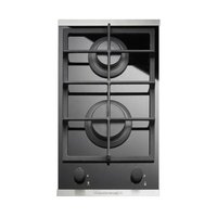
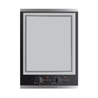
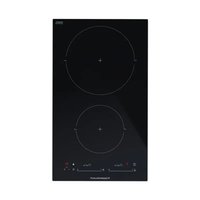
GKS3820.0ED - Hob Küppersbusch - Free user manual and instructions
Find the device manual for free GKS3820.0ED Küppersbusch in PDF.


| Product type | Gas cooktop |
| Brand | Küppersbusch |
| Model | GKS3820.0ED |
| Number of burners | 4 |
| DUAL burner | Max power 6000 W (inner crown 800 W) |
| Rapid burner | 3000 W |
| Semi-rapid burner | 1750 W |
| Auxiliary burner | 1000 W |
| Power supply | Gas (Butane/Propane/Natural) and electric 220-240 V~ |
| Ignition | Automatic electric and manual (match) |
| Safety | Safety thermocouple on all burners |
| Gas categories | I3+ (LPG), I2E (Natural gas), II2E+3+, II2H3+ |
| Total power (Natural gas) | 6.0 kW |
| Electrical voltage | 220-240 V~ |
| Energy efficiency class | 58.3% (according to EU regulation 66/2014) |
| Surface material | Glass |
| Cleaning | Damp sponge, vinegar or lemon for stubborn stains; do not use abrasive products |
| Burner maintenance | Regular cleaning of grates, flame spreaders and injectors; do not wash in dishwasher |
| Spare parts | Injectors, taps, power cable available from authorized centers |
| Certifications | CE, European directives (gas safety, EMC, low voltage) |
| Warranty | Subject to proper installation by a qualified installer |
Frequently Asked Questions - GKS3820.0ED Küppersbusch
User questions about GKS3820.0ED Küppersbusch
0 question about this device. Answer the ones you know or ask your own.
Ask a new question about this device
Download the instructions for your Hob in PDF format for free! Find your manual GKS3820.0ED - Küppersbusch and take your electronic device back in hand. On this page are published all the documents necessary for the use of your device. GKS3820.0ED by Küppersbusch.
USER MANUAL GKS3820.0ED Küppersbusch
natural_image
Two identical grid diagrams with circular cutouts, no text or symbols present
GWS3811.0ED
GKS3820.0ED
GKS9851.0ED
GMS7651.0E
GMS9651.0E
Please read the users and installation instructions carefully before installation of the appliance and before starting to use it.
natural_image
Simple circular diagram with a dot, two flame icons, and a small circle (no text or labels)● Geschlossene Position
Position fermée
Stand gesloten
Θέση κλειστό
Kapalı pozisyon
Pozice zavřeno
Poloha vypnuté
Closed position
Posizione di chiuso
Posición de cerrado
FIG. 1

Position maximale Gasausgabe
Position de distribution maximale de gaz Stand maximale gastoevoer
Θέση μέγιστης δαροχής αερίου
Maksimum gaz verme pozisyonu
Pozice maximální dodávky plynu
Poloha maximum plynu
Full on position
Posizione di massima erogazione gas
Posición de máximo suministro de gas

Position minimale Gasausgabe
Position de distribution minimale de gaz
Stand minimale gastoevoer
Θέση ελάχιστης δαροχής αερίου
Minimum gaz verme pozisyonu
Pozice minimální dodávky plynu
Poloha minimum plynu
Reduced rate position
Posizione di miniima erogazione gas
Posición de mínimo suministro de gas
FIG. 2
natural_image
Line drawings of two cooking pots with crossed diagonals and a wavy base, no text or symbols present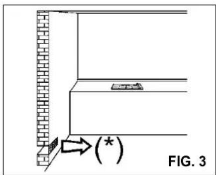
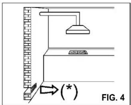
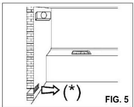
(*) LUCHTINGANG: ZIE HOOFDSTUK INSTALLATIE (PARAGRAFEN 5 EN 6)
(*) ENTREE D'AIR: VOIR CHAPITRE INSTALLATION (PARAGRAPHES 5 ET 6)
(*) LUCHTINGANG: ZIE HOOFDSTUK INSTALLATIE (PARAGRAFEN 5 EN 6)
(*) ΕΙΣΟΔΟΣ ΑΕΡΑ: ΒΛΕΠΕ ΚΕΦΑΛΑΙΟ ΤΟΠΟΘΕΤΗΣΗΣ (ΠΑΡΑΓΡΑΦΟΙ 5 ΚΑΙ 6)
(*) HAVA GİRİŞİ: MONTAJLA İLGİLİ 5 VE 6 NOLU PARAGRAFLARA BAKINIZ
(*) PŘÍVOD VZDUCHU: VIZ. KAPITOLA TIKAJÍCÍ SE INSTALACE (BOD 5 A 6)
(*) PRÍVOD VZDUCH: VID. KAPITOLA INSTALÁCIE (PARAGRAF 5 A 6)
(*) AIR INLET: SEE INSTALLATION CHAPTER (PARAGRAPHS 5 AND 6)
(*) ENTRATA ARIA: VEDI CAPITOLO INSTALLAZIONE (PARAGRAFI 5 E 6)
(*) ENTRADA DE AIRE: VER EL CAPÍTULO DE INSTALACIÓN (APARTADOS 5 Y 6)
REINIGUNG - NETTOYAGE - REINIGING - KAΘΑΡΙΣΜΟΣ - TEMİZLEME ČIŠTĚNÍ - ČISTENIE - CLEANING - PULIZIA - LIMPIEZA
natural_image
Line drawing of a hand using a tool to apply a small component onto a circular base, labeled 'FIG. 6' (no text or symbols on the diagram itself)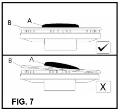
INSTALLATION - INSTALLATIE - EΓΚΑΤΑΣΤΑΣΗ - MONTAJ - INSTALAC INŠTALÁCIA - INSTALLATION - INSTALLAZIONE - INSTALACIÓN
| A B C D E F | |||||||
| GWS3811.0ED - GKS3820.0ED | 1F - 2F (30) | 282 | 473 | 63.5 | 63.5 | 300 | Min. 70 mm |
| GKS9851.0ED | 5F (90) | 833 | 473 | 63.5 | 63.5 | 300 | Min. 70 mm |
| GMS7651.0E | 5F (70) | 553 | 473 | 63.5 | 63.5 | 173.5 | Min. 70 mm |
| GMS9651.0E | 5F (90) | 833 | 475 | 62.5 | 62.5 | 300 | Min. 70 mm |
EINZUHALTENDE MASSE (mm) DIMENSIONS A RESPECTER (en mm) AAN TE HOUDEN AFMETINGEN (mm) MEΓΕΘΗ ΠΟΥ ΠΡΕΠΕΙ ΝΑ ΤΗΡΗΘΟΥΝ (σε mm) EBATLARA EŞ DEĞER (mm) ROZMĚRY, KTERÉ MUSÍ BIT DODRŽENY (v mm) ZÁVÄZNÉ MIERY (v mm) COMPLY WITH THE DIMENSIONS (in mm) MISURE DA RISPETTARE (in mm) MEDIDAS QUE ES PRECISO RESPETAR (en mm)
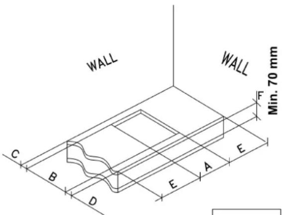
FIG. 9
INSTALLATION - INSTALLATIE - EΓΚΑΤΑΣΤΑΣΗ - MONTAJ - INSTALAC INŠTALÁCIA - INSTALLATION - INSTALLAZIONE - INSTALACIÓN
GWS3811.0ED
GKS3820.0ED
GKS9851.0ED
GMS7651.0E
GMS9651.0E
natural_image
Technical line drawing of a mechanical component with labeled point E (no text or symbols beyond label)FIG. 10
natural_image
Close-up of a mechanical component with a circular feature and a labeled section 'E' (no readable text or symbols beyond label)GMS7651.0E - GMS9651.0E
GWS3811.0ED - GKS9851.0ED
- GKS3820.0ED
EINSTELLUNGSARBEITEN - REGLAGES - REGELINGEN P'YOMIŞH - AYARLAMALAR -SEŘÍZENÍ - NASTAVENIA INSTALLATION - REGOLAZIONI - REGULACIONES
UMÄNDERUNGEN - TRANSFORMATIONS - VERANDERINGEN METATPOΠΕΣ - ÇEVİRMELER - PŘEMĚNA - VIMENY CONVERSION - TRASFORMAZIONI - TRANSFORMACIONES
natural_image
Diagram of a curved pipe or tube with a base and labeled point B, no text or symbols presentExtinction:
comply with the following instructions, before remounting the parts:
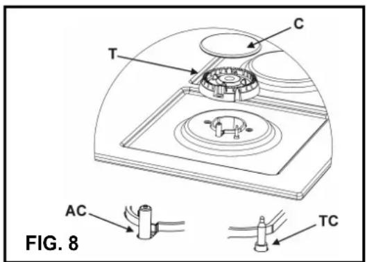
- check that burner head slots "T" (fig. 8) have not become clogged by foreign bodies.
- Check that enamelled burner cap "A", "B", "C" (fig. 7 and 8) have correctly positioned on the burner head. It must be steady.
- The pan support must be placed in the appropriate centering pins verifying the perfect stability.
- Do not force the taps if they are difficult open or close. Contact the technical assistance service for repairs.
- Don't use steam jets for the equipment cleaning.
ATTENTION!
pie
| Category | Value | |---|---| | EE_gas hob | 63.8% | | Other | 0.0% |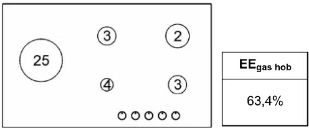
TABLEAU
| BRULEURS | GAZ | PRESSION D'EXERCICE mbar | DEBIT THERMIQUE | DIAMETRE INJECTEUR Max/100 mm | DEBIT THERMIQUE (W) | ||||
| N° | DENOMINATION | g/h l/h Min. | EEgas burner* | ||||||
| 1 | WOK Double couronne** | G 30 - BUTANE | 28 - 30 | 291 | 100 B | 1800 | 4000 | 59.0% | |
| G 31 - PROPANE | 37 | 286 | 100 B | 1800 | 4000 | ||||
| G 20 - NATUREL | 20 | 381 | 145 A | 1800 | 4000 | ||||
| G 25 - NATUREL | 25 | 443 | 148 A | 1800 | 4000 | ||||
| 2 | Rapide | G 30 - BUTANE | 28 - 30 | 218 | 87 B | 800 | 3000 | 65.3% | |
| G 31 - PROPANE | 37 | 214 | 87 B | 800 | 3000 | ||||
| G 20 - NATUREL | 20 | 286 | 128 A | 800 | 3000 | ||||
| G 25 - NATUREL | 25 | 332 | 135 A | 800 | 3000 | ||||
| 3 | Semi-rapide | G 30 - BUTANE | 28 - 30 | 127 | 66 B | 550 | 1750 | 65.5% | |
| G 31 - PROPANE | 37 | 125 | 66 B | 550 | 1750 | ||||
| G 20 - NATUREL | 20 | 167 | 98 A | 550 | 1750 | ||||
| G 25 - NATUREL | 25 | 194 | 103 A | 550 | 1750 | ||||
| 4 | Auxiliaire | G 30 - BUTANE | 28 - 30 | 73 | 50 B | 450 | 1000 | N.A. | |
| G 31 - PROPANE | 37 | 71 | 50 B | 450 | 1000 | ||||
| G 20 - NATUREL | 20 | 95 | 77 A | 450 | 1000 | ||||
| G 25 - NATUREL | 25 | 111 | 77 A | 450 | 1000 | ||||
| 25 | DUAL total** | G 30 - BUTANE | 28 - 30 | 345 | 2 × 72 B + 46 B | 2700 | 4750 | 57.4% | |
| G 31 - PROPANE | 37 | 339 | 2 × 72 B + 46 B | 2700 | 4750 | ||||
| G 20 - NATUREL | 20 | 452 | 2 × 115 A + 71 A | 2700 | 5000 | ||||
| G 25 - NATUREL | 25 | 526 | 2 × 118 A + 71 A | 2700 | 4750 | ||||
| DUAL central | G 30 - BUTANE | 28 - 30 | 58 | 46 B | 300 | 800 | N.A. | ||
| G 31 - PROPANE | 37 | 27 | 46 B | 300 | 800 | ||||
| G 20 - NATUREL | 20 | 76 | 71 A | 300 | 800 | ||||
| G 25 - NATUREL | 25 | 89 | 71 A | 300 | 800 | ||||
FREQUENCE = 50/60 Hz
GKS3820.0ED
CATEGORÍA = 13+
CATEGORÍA = 12E
CATEGORÍA = II2E+3+
CATEGORÍA = II2H3+
G 30 - BUTANE = 28 - 30 mbar
G 31 - PROPANE = 37 mbar
G 20 - NATUREL = 20 mbar
G 25 - NATUREL = 25 mbar
Σ Qn Gas Naturel = 4.75 kW
Σ Qn GPL = 345 g/h (G30)
Σ Qn GPL = 339 g/h (G31)
TENSION = 220 - 240 V\~
FREQUENCE = 50/60 Hz
GKS9851.0ED
CATEGORÍA = 13+
CATEGORÍA = 12E
CATEGORÍA = II2E+3+
CATEGORÍA = II2H3+
G 30 - BUTANE = 28 - 30 mbar
G 31 - PROPANE = 37 mbar
G 20 - NATUREL = 20 mbar
G 25 - NATUREL = 25 mbar
Σ Qn Gas Naturel = 13.5 kW
Σ Qn GPL = 981 g/h (G30)
Σ Qn GPL = 964 g/h (G31)
TENSION = 220 - 240 V\~
FREQUENCE = 50/60 Hz
GMS7651.0E
CATEGORÍA = 13+
CATEGORÍA = 12E
CATEGORÍA = II2E+3+
CATEGORÍA = II2H3+
G 30 - BUTANE = 28 - 30 mbar
G 31 - PROPANE = 37 mbar
G 20 - NATUREL = 20 mbar
G 25 - NATUREL = 25 mbar
Σ Qn Gas Naturale = 11.5 kW
Σ Qn GPL = 545 g/h (G30)
Σ Qn GPL = 536 g/h (G31)
TENSION = 220 - 240 V\~
FREQUENCE = 50/60 Hz
GMS9651.0E
CATEGORÍA = 13+
CATEGORÍA = I2E
CATEGORÍA = II2E+3+
CATEGORÍA = II2H3+
G 30 - BUTANE = 28 - 30 mbar
G 31 - PROPANE = 37 mbar
G 20 - NATUREL = 20 mbar
G 25 - NATUREL = 25 mbar
Σ Qn GPL = 12.25 kW
Σ Qn Gas Natural = 12.50 kW
Σ Qn GPL = 891 (G30)
Σ Qn GPL = 875 (G31)
TENSION = 220 - 240 V\~
FREQUENCE = 50/60 Hz
BESCHRIJVING KOOKPLATEN
TYPE: PCK 306090
GWS3811.0ED
GKS3820.0ED
GKS9851.0ED
BESCHRIJVING KOOKPLATEN
TYPE: PCZJ 6075 TYPE: PCZJ 90
GMS7651.0E GMS9651.0E
Kapatma:
POKYNY DOLEŽITÉ PRE INSTALÁCIU
Σ Qn Gaz Zemni = 6.0 kW
Σ Qn GPL = 436 g/h (G30)
Σ Qn GPL = 429 g/h (G31)
Příkon = 220 - 240 V \~
Frekvence = 50/60 Hz
GKS3820.0ED
KAT.: II2H3B/P
G30 - Bután = 30 mbar
G31 - Propán = 30 mbar
G20 - Zemni = 20 mbar
Σ Qn Gaz Zemni = 4.75 kW
Σ Qn GPL = 345 g/h (G30)
Σ Qn GPL = 339 g/h (G31)
Příkon = 220 - 240 V \~
Frekvence = 50/60 Hz
GKS9851.0ED
KAT.: II2H3B/P
G30 - Bután = 30 mbar
G31 - Propán = 30 mbar
G20 - Zemni = 20 mbar
Σ Qn Gaz Zemni = 13.5 kW
Σ Qn GPL = 981 g/h (G30)
Σ Qn GPL = 964 g/h (G31)
Příkon = 220 - 240 V \~
Frekvence = 50/60 Hz
GMS7651.0E
KAT.: II2H3B/P
G30 - Bután = 30 mbar
G31 - Propán = 30 mbar
G20 - Zemni = 20 mbar
Σ Qn Gaz Zemni = 11.5 kW
Σ Qn GPL = 545 g/h (G30)
Σ Qn GPL = 536 g/h (G31)
Příkon = 220 - 240 V \~
Frekvence = 50/60 Hz
GMS9651.0E
KAT.: II2H3B/P
G30 - Bután = 30 mbar
G31 - Propán = 30 mbar
G20 - Zemni = 20 mbar
Σ Qn GPL = 12.25 kW
Σ Qn Gaz Zemni = 12.50 kW
Σ Qn GPL = 891 (G30)
Σ Qn GPL = 875 (G31)
Příkon = 220 - 240 V \~
Frekvence = 50/60 Hz
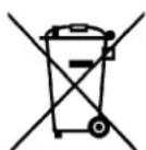
Tento spotrebič je označení v súlade s európskou smernicou 2002/96/EG o nakladaní s použitimi elektrickimi a elektronickimi zariadeniami (waste electrical and electronic equipment - WEEE).
Children less than 8 years of age shall be kept away unless continuously supervised.
This appliance can be used by children aged from 8 years and above and persons with reduced physical, sensory or mental capabilities or lack of experience and knowledge if they have been given supervision or instruction concerning use of the appliance in a safe way and understand the hazards involved.
Children shall not play with the appliance.
Cleaning and user maintenance shall not be made by children without supervision.
Dear customer,
thank you for buying one of our products.
We are sure that this new, modern, functional and practical appliance, made using the finest quality materials, will fully satisfy your requirements. This new appliance is very easy to use, but in order to obtain the best results, we strongly recommend that you read this booklet carefully before use.
These instructions are valid exclusively for countries the identification symbols of which appear on the cover of the instruction booklet and the label on the appliance.
The manufacturer cannot be considered responsible for any damages to people or to things in the event of incorrect installation or improper use of the appliance.
The Manufacturer cannot be held responsible for any imprecision due to printing or copying errors contained in this booklet. The figures shown are purely indicative. We reserve the right to make any changes to our products which we consider to be necessary or useful, also in the interest of the user, without affecting their essential characteristics in terms of functionality and safety. This cook top was designed to be used exclusively as a cooking appliance: any other use (such as heating rooms) is to be considered improper and dangerous.
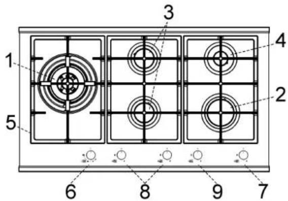
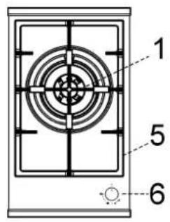
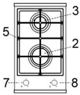
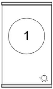
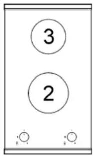
DESCRIPTION OF HOBS
TYPE: PCK 306090
GWS3811.0ED
GKS3820.0ED
GKS9851.0ED
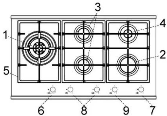
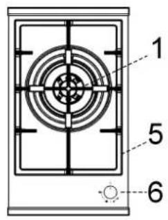
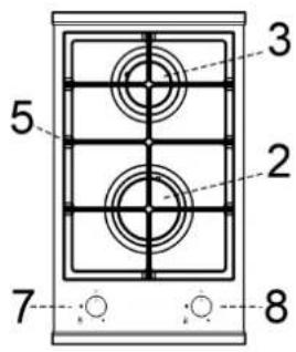
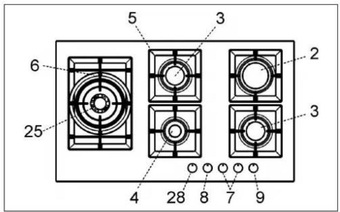
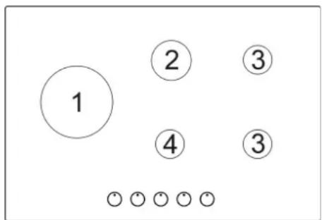
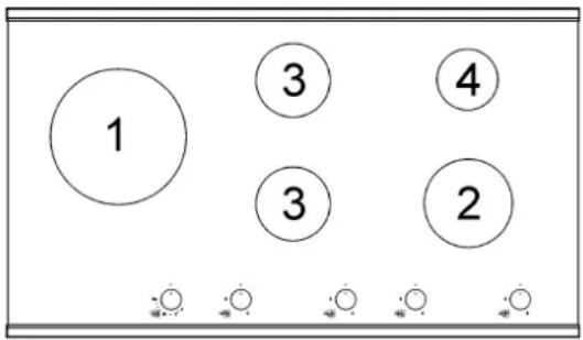
1 DUAL burner of 6000 W
2 Rapid burner of 3000 W
3 Semirapid burner of 1750 W
4 Auxiliary burner of 1000 W
5 Pan support
6 Burner n° 1 control knob
7 Burner n° 2 control knob
8 Burner n° 3 control knob
9 Burner n° 4 control knob
Attention: this appliance has been manufactured for domestic use only and it employment by private person.
GB
IE
MT
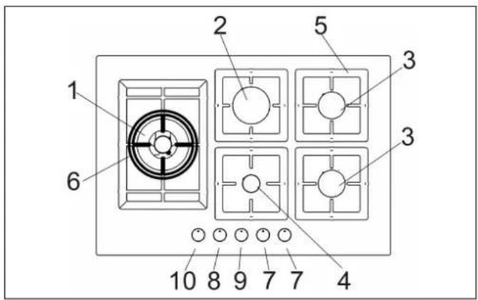
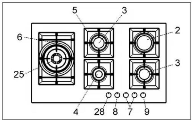
DESCRIPTION OF HOBS
TYPE: PCZJ 6075 TYPE: PCZJ 90
GMS7651.0E GMS9651.0E
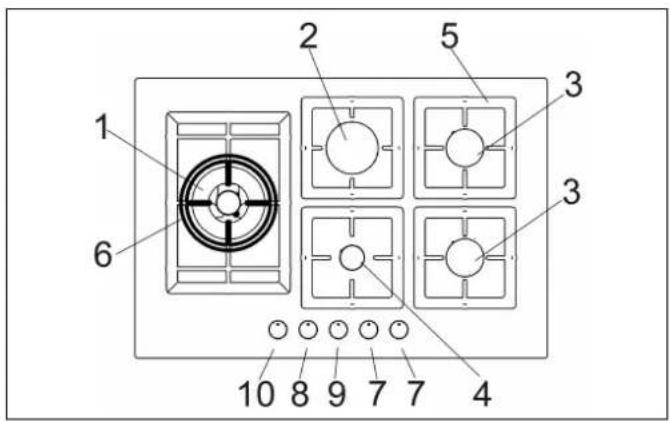
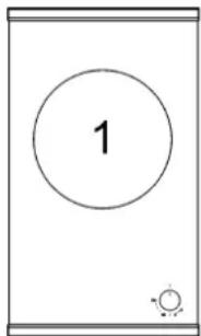
1 Double crown Wok burner of 4000 W
2 Rapid gas burner of 3000 W
3 Semirapid gas burner of 1750 W
4 Auxiliary gas burner of 1000 W
5 Pan support
6 Pan support WOK (only on Double crown burner and DUAL)
7 Burner n° 3 control knob
8 Burner n° 4 control knob
9 Burner n° 2 control knob
10 Burner n° 1 control knob
25 DUAL burner of 4750 ÷ 5000 W
28 Burner n° 25 control knob
Attention: this appliance has been manufactured for domestic use only and it employment by private person.
USE
1) TRADITIONAL BURNERS
On the surface of the hob, there is a serigraphic figure above each knob, indicating the burner to which the knob refers. After turning on the gas at the main or opening the valve on the gas bottle, light the burners as indicated below:
- Manual ignition
Push and turn the knob corresponding to the required burner in an anticlockwise direction until it reaches the full on position (large flame fig. 1), then place a lighted match near the burner.
- Automatic electric ignition
Press the knob corresponding to the burner to use and turn it clockwise to the "Maximum" position (big flame fig. 1) pressing the knob right down.
- Lighting burners fitted with a safety cut-off device
For burners fitted with a safety cut-off device, turn the knob corresponding to the burner to use anti-clockwise to the "Maximum" position (big flame fig. 1) until it stops and then press the knob. Continue pressing the knob for about 10 seconds after the burner has been lit.
Should the flames accidentally go out, turn the burner control knob off and wait at least 1 min before attempting to light it again.
How to use the burners
To obtain maximum performance with minimum gas consumption, remember the following:
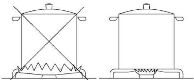
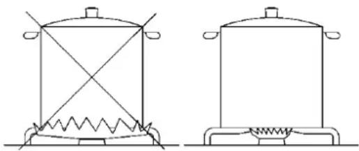
- use suitable pans for each burner (see the table below and fig. 2).
- When boiling point is reached, turn the knob to the "Minimum" position (small flame fig. 1).
- Always use pans with lids.
1/A) DUAL BURNERS
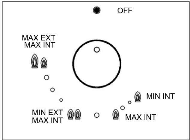
Separate regulation of the inner and outer rings (in practical terms, a dual burner controlled by a single knob), offering very flexible use thanks to the possibility to light either the inner flame only or the whole burner (inner and outer flame at the same time).
LIGHTING AND USING THE "DUAL" BURNER Stand the pan on the burner before lighting.
Despite being controlled by a single knob, the "DUAL" burner can be used in two different ways.
A) - Using the complete burner:
starting from the off position • You must first press the knob, simultaneously turning it anti-clockwise, until the indicator points to the maximum delivery position obtaining the maximum flow capacity of both flames.
When the flames are lit, keep the knob pressed for a few seconds, until the device automatically keeps the burner lit.
It is now possible to regulate the intensity of the flame by turning the knob anti-clockwise (from the maximum flow capacity position of the inner and outer flames to the maximum flow capacity of the inner flame and the minimum of the outer flame.
To turn off the burner, turn the knob clockwise, realigning the indicator with the • off symbol.
B) - Using the inner flame only:
after lighting the burner and regulating the inner flame to maximum flow capacity and the outer flame to minimum flow capacity as described above, turn the knob anti-clockwise until it clicks once. The inner flame is now at maximum flow capacity while the outer flame is turned off.
Continue turning anti-clockwise to regulate the inner flame to the minimum flow capacity.
Turning off:
to turn off the burner, turn the knob clockwise, realigning the indicator with the • off symbol.
Once the “DUAL” burner is operating in either of the two modes described, it is possible to swap from one mode to the other by simply turning the knob to the position required.

USE
| Burners | Power (W) | Pan cm |
| DUAL total 4750 ÷ 6000 | 22 ÷ 30 | |
| DUAL central 900 | 8 ÷ 16 | |
| Double crown Wok burner | 4000 | 22 ÷ 26 |
| Rapid | 3000 | 20 ÷ 22 |
| Semirapid | 1750 | 16 ÷ 18 |
| Auxiliary | 1000 | 10 ÷ 14 |
WARNINGS:
- burners fitted with safety cut-off devices can only be lit when the knob is in the "Maximum" position (big flame fig. 1).
- In the absence of electricity, the burners can be lit with matches.
- Never leave the appliance unattended while the burners are in use and ensure that children are kept at a safe distance. Make sure that pan handles are correctly positioned and supervise the cooking of foods in oil and fat, as these are highly flammable.
- Do not use spray s near the appliance during use.
- Do not drag pans across the glass hob as this may scratch the surface.
- Do not use the hob as a work surface.
- Do not place pans with an unstable or deformed bottom on the burner, as these may tip or spill their contents, causing accidents.
- The pans must not extend beyond the edge of the hob.
WARNINGS AND RECOMMENDATIONS FOR THE USER:
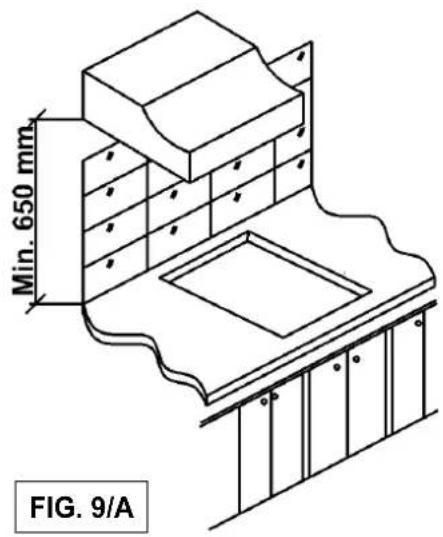
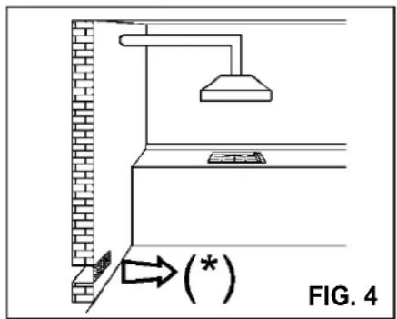
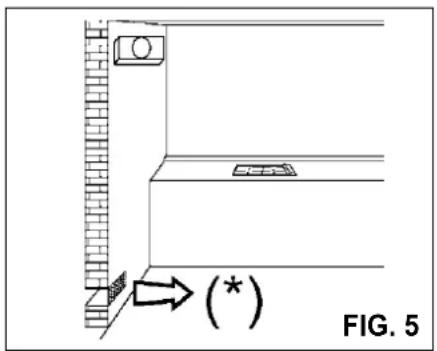
- use of a gas cooking appliance produces heat and moisture in the room in which it is installed. The room must therefore be well ventilated by keeping the natural air vents clear (fig. 3) and by activating the mechanical aeration device (suction hood or electric fan fig. 4 and fig. 5).
- Intensive and lengthy use of the appliance may require additional ventilation. This can be achieved by opening a window or by increasing the power of the mechanical exhausting system if installed.
- Do not attempt to change the technical characteristics of the product because it can be dangerous.
- If you should not to use this appliance any more (or replace an old model), before disposing of it, make it inoperative in conformity with current law on the protection of health and the prevention of environmental pollution by making its dangerous parts harmless, especially for children who might play on an abandoned appliance.
- Do not touch the appliance with wet or damp hands or feet.
- Do not use the appliance barefoot.
- The manufacturer will not be liable for any damage resulting from improper, incorrect or unreasonable use.
- During, and immediately after operation, some parts of the cook top are very hot: avoid touching them.
- After using the cook top, make sure that the knob is in the closed position and close the main tap of the gas supply or gas cylinder.
- If the gas taps are not operating correctly, call the Service Department.
CLEANING
IMPORTANT:
always disconnect the appliance from the gas and electricity mains before carrying out any cleaning operation.
2) GAS HOB CERAMIC
It is very important to clean the surface soon after every use, when the glass is still tepid.
Do not use metallic sponges, powder abrasives or corrosive sprays.
Depending on the dirty level we recommend:
- slights stains: it is enough the use of a moist clean rag.
- Marks of liquid, overflowed from the pot, can be removed using vinegar or lemon.
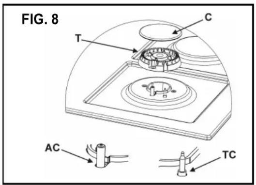
Periodically wash the hot plate, the enamelled stell pan support, the enamelled burner caps "A", "B" and "C" and the burner heads "T" (see fig. 7 and 8) with lukewarm soapy water. They should also be cleaned plugs "AC" and flame detection "TC" (see fig. 8).
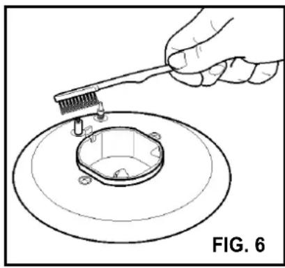
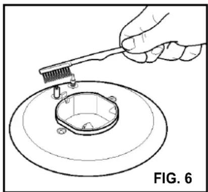
Clean them gently with a small nylon brush as shown (see fig. 6) and allow to dry fully.
Do not wash in the dishwasher.
Do not allow vinegar, coffee, milk, salted water, lemon or tomato juice from remaining in contact with the enamelled surfaces for long periods of time.
WARNINGS:
comply with the following instructions, before remounting the parts:
- check that burner head slots "T" (fig. 8) have not become clogged by foreign bodies.
- Check that enamelled burner cap "A", "B", "C" (fig. 7 and 8) have correctly positioned on the burner head. It must be steady.
- The pan support must be placed in the appropriate centering pins verifying the perfect stability.
- Do not force the taps if they are difficult open or close. Contact the technical assistance service for repairs.
- Don't use steam jets for the equipment cleaning.
Note: continuous use could cause the burners to change colour due to the high temperature.
CAUTION:
In case of hotplate glass breakage:
- shut immediately off all burners and any electrical heating element and isolate the appliance from the power supply;
- do not touch the appliance surface;
•do not use the appliance.



INSTALLATION
TECHNICAL INFORMATION FOR THE INSTALLER
Installation, adjustments of controls and maintenance must only be carried out by a qualified engineer (law n° 46 and D.P.R. 447). The appliance must be correctly installed in conformity with current law and the manufacturer's instructions.
Incorrect installation may cause damage to persons, animals or property for which the Manufacturer shall not be considered responsible.
During the life of the system, the automatic safety or regulating devices on the appliance may only be modified by the manufacturer or by his duly authorized dealer.
3) INSTALLING THE HOB
Check that the appliance is in a good condition after having removed the outer packaging and internal wrappings from around the various loose parts. In case of doubt, do not use the appliance and contact qualified personnel.
Never leave the packaging materials (cardboard, bags, polystyrene foam, nails, etc.) within children's reach since they could become potential sources of danger.
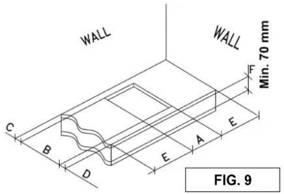
The measurements of the opening made in the top of the modular cabinet and into which the cooktop will be installed are indicated in either fig. 9.
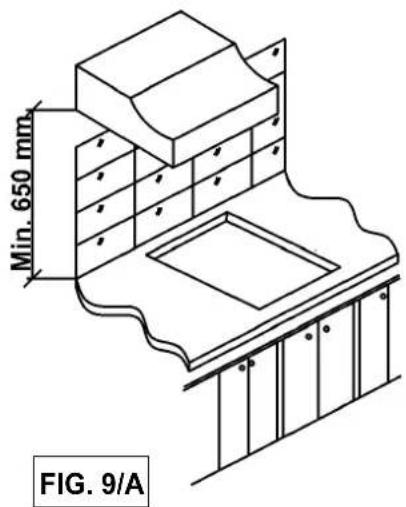
Always comply with the measurements given for the hole into which the appliance will be recessed (see fig. 9 and 9/A).
The prospective walls (left or right) that exceed the working table in height must be at a minimum distance from the cutting as mentioned both in the columns “E” of the scheme.
The appliance belongs to class 3 and is therefore subject to all the provisions established by the provisions governing such appliances.
IMPORTANT!
A perfect installation, adjustment or transformation of the cook top to use other gases requires a QUALIFIED INSTALLER: a failure to follow this rule will void the warranty.
4) FITTING THE HOB
The hob is equipped with a special seal to avoid any infiltration of liquid into the unit. To apply this seal correctly, please follow the instructions given below carefully:
- remove all the mobile parts of the hob.
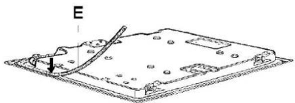
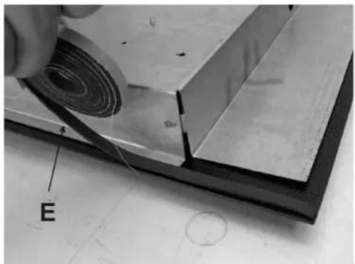
- Cut the seal into 4 strips of the lengths suitable to fit it along the 4 sides of the glass.
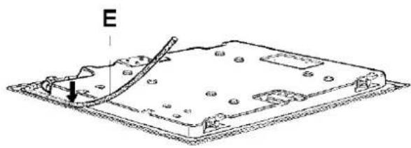
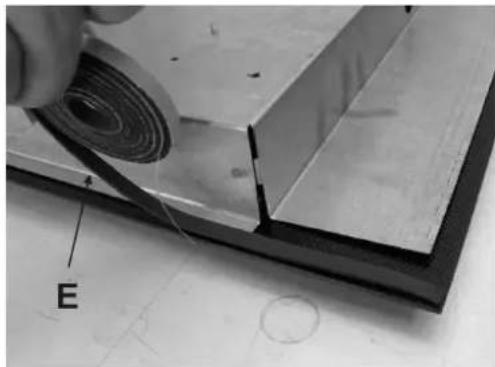
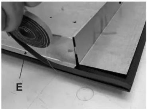
- Turn the hob upside down and place the adhesive side of the seal "E" (fig. 10) correctly under the edge of the hob so that the outer edge of the seal perfectly matches the outer perimeter edge of the glass. The ends of the strips must match without overlapping.
- Stick the seal to the glass evenly and securely, using your fingers to press it into place.
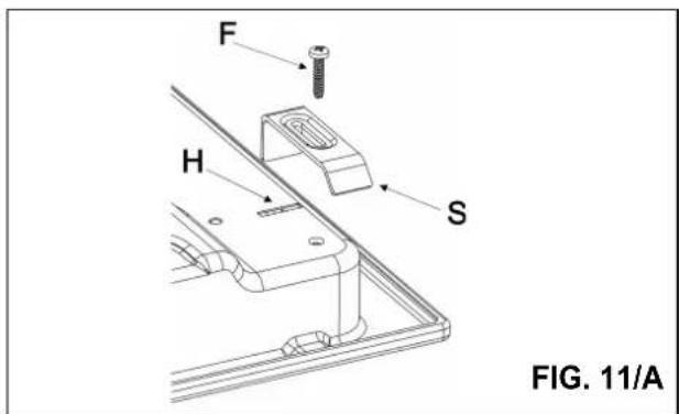
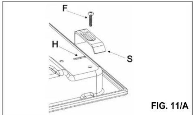
- For GMS7651.0E-GMS9651.0E: position the hob with the proper brackets "S" and fit the prominent part into the porthole "H" on the bottom; turn the screw "F" until the bracket "S" stick on the top (fig. 11/A).
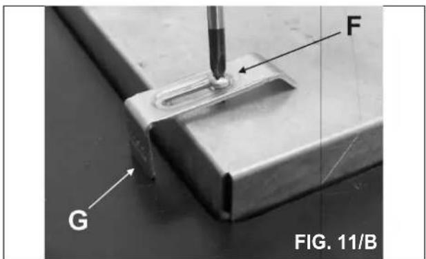
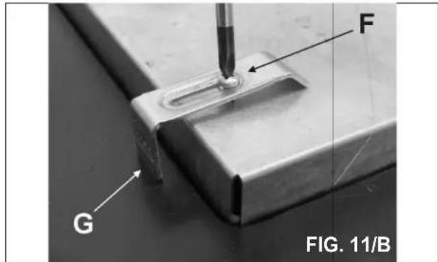
- For GWS3811.0ED - GKS9851.0ED-GKS3820.0ED: position the hob in the hole in the unit and fasten it in place using the appropriate screws "F" of the fastening hooks "G" (see fig. 11/B).
- In order to avoid accidental contact with the surface of the box of the overheated hob during use, it is necessary to install a wooden divider at a minimum distance of 70 mm from the top, fastening it in place with screws (fig. 9).
Caution: Do not allow the glass lay directly on the work top. it is the bottomshelf that has to be in touch with the work top.

GB
IE
MT
INSTALLATION
IMPORTANT INSTALLATION INSTRUCTIONS
The installer should note that the appliance that side walls should be no higher than the hot plate itself. Furthermore, the rear wall, the surfaces surrounding and adjacent to the appliance must be able to withstand a temperature of 90 °C.
The adhesive used to stick the plastic laminate to the cabinet must be able to withstand a temperature of not less than 150 °C otherwise the laminate could come unstuck.
The appliance must be installed in compliance with BS 6172 1990, BS 5440 part. 2 1989 and BS 6891 1988.
This appliance is not connected to a device able to dispose of the combustion fumes. It must therefore be connected in compliance with the above mentioned installation standards. Particular care should be paid to the following provisions governing ventilation and aeration.
5) ROOM VENTILATION
To ensure correct operation of the appliance, it is important to ensure that the room where the hot plate is installed has sufficient ventilation, as set out in BS 5440 part 2. 1989. See table below.
| Type of appliance | Volume of room cubic metres | Min. size of vent sq. cm. | Openable window or alternative method of venting to the outside |
| Domestic ovens hotplates or any combinations | 5 | 100 | yes |
| 5 to 10 | 50 | yes | |
| 11 to 20 | nil | yes | |
| 20 and above | nil | yes |
Natural air flow must enter directly through permanent openings in the walls of the room in question. These must open towards the outside and possess a minimum section of 100 cm^2 see fig. 3). It must be impossible to obstruct these openings. Indirect ventilation with air drawn from adjacent rooms is permitted in strict compliance with the provisions in force.
6) LOCATION AND AERATION
Gas cooking appliances must always dispose of their combustion fumes through hoods. These must be connected to flues, chimneys or straight outside (see fig. 4). If it is not possible to install a hood, an electric fan can be installed on a window or on a wall facing
outside (see fig. 5). This must be activated at the same time as the appliance, so long as the specifications in the provisions in force are strictly complied with.
7) GAS CONNECTION
Before connecting the appliance, check that the values on the data label affixed to the underside of the hot plate correspond to those of the gas mains in the home.
A label on this manual and on the product indicates the type of gas and pressure adjustment.
WARNING:
a gas hot plate can only be connected by a CORGI Registered engineer.
Installations should be carried out in accordance with BS 6891 1988 and must comply with the Gas Safety Regulations.
All hot plate installations must include an isolation tap.
GAS PRESSURE TEST
Some hot plates models have a test point fitted under the control panel, to conduct a gas pressure test proceed as follows:
- turn off the gas supply.
- Remove screw in the pressure test point, place test gauge connecting tube on test point.
- Fit a burner ring and cap onto burner assembly, replace control knob onto corresponding control tap for the burner.
- Turn on gas and ascertain working pressure.
After test, turn off control tap, turn off gas supply, disconnect test gauge connecting tube.
Replace the test point screw, turn gas back on and test for soundness. Reassemble the hotplate.
IMPORTANT:
the appliance complies with the provisions of the following CE Directives:
2009/142 regarding gas safety.
INSTALLATION
The appliance must be installed following the manufacturer's instructions. The manufacturer will not be liable for injury to persons or animals or property damage caused by an incorrect installation.
The electrical connections of the appliance must be carried out in compliance with the provisions and standards in force.
Before connecting the appliance, check that:
- The voltage matches the value shown on the specification plate and the section of the wires of the electrical system can support the load, which is also indicated on the specification plate.
- The electrical capacity of the mains supply and current sockets suit the maximum power rating of the appliance (consult the data label applied to the underside of the cooktop).
- The socket or system has an efficient earth connection in compliance with the provisions and standards in force. The manufacturer declines all responsibility for failing to comply with these provisions.
When the appliance is connected to the electricity main by a socket:
- Fit a standard plug suited to the load indicated on the data label to the cable.
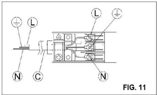
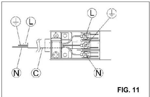
- Fit the wires following figure 11, taking care of respecting the following correspondences:
letter L (live) = brown wire;
letter N (neutral) = blue wire;
earth symbol ≡ green - yellow wire.
- The power supply cable must be positioned so that no part of it is able to reach an temperature of 90 °C.
- Never use reductions, adapters of shunts for connection since these could create false contacts and lead to dangerous overheating.
When the appliance is connected straight to the electricity main:
- Install an omnipolar circuit-breaker between the appliance and the electricity main. This circuit-breaker should be sized according to the load rating of the appliance and possess a minimum 3 mm gap between its contacts.
- Remember that the earth wire must not be interrupted by the circuit-breaker.
- The electrical connection may also be protected by a high sensitivity differential circuit-breaker.
You are strongly advised to fix the relative yellow-green earth wire to an efficient earthing system.
Before performing any service on the electrical part of the appliance, it must absolutely be disconnected from the electrical network.
If the installation requires modifications to the home's electrical system or if the socket is incompatible with the appliance's plug, have changes or replacements performed by professionally-qualified person. In particular, this person must also make sure that the section of the wires of the socket is suitable for the power absorbed by the appliance.
WARNINGS:
all our products are conform with the European Norms and relative amendments.
The product is therefore conform with the requirements of the European Directivesin force relating to:
- compatibility electromagnetic (EMC);
- electrical security (LVD);
- restriction of use of certain hazardous substances (RoHS);
- EcoDesign (ERP).
REGULATION
Before performing any regulation, disconnect the electricity supply to the appliance.
After carrying out any regulation or pre-regulation operations, any seals must be replaced by the technician.
The regulation of primary air to our burners is not necessary.
9) VALVES
Regulation of the "Minimum":
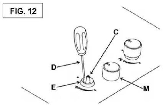
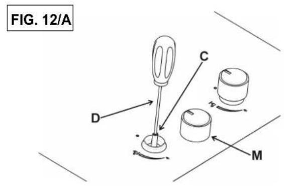
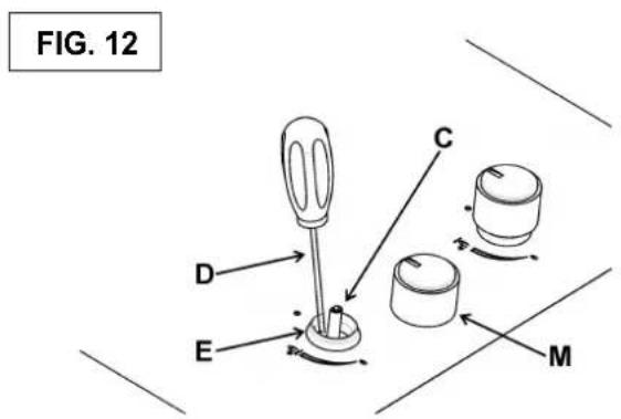
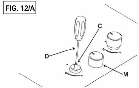
- Remove knob "M" (fig. 12 and 12/A) of the tap, which is simply pressed on to its rod. The bypass for minimal rate regulation can be: beside the tap (fig. 12) or inside the shaft. In any case, to access to regulation, it can be done trought the insertion of a small screwdriver "D" beside the tap (fig. 12) or in the hole "C" inside the shaft of the tap (fig 12/A). Turn the throttle screw to the right or left until the burner flame has been adequately regulated to the "Reduced rate" position.
The flame should not be too low: the lowest small flame should be continuous and steady. Re-assemble the several components.
It is understood that the aforementioned regulation must only be carried out with burners which use G20, while for burners which use G30 the screw must be blocked completely.
The operations described above can be carried out easily, whatever the position of the hob or however it is fastened to the unit.
THE BURNERS DO NOT REQUIRE ANY REGULATION OF THE PRIMARY AIR.
WARNING:
To adjust the minimum "DUAL" burner first remove the bushing "E" (fig. 12).
In the case of a “DUAL” burner, the regulation screw situated inside the post of the valve regulates the central flame, while the screw next to the valve regulates the outer flame.
10) REPLACING NOZZLES
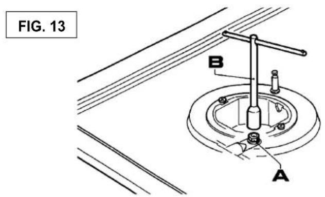
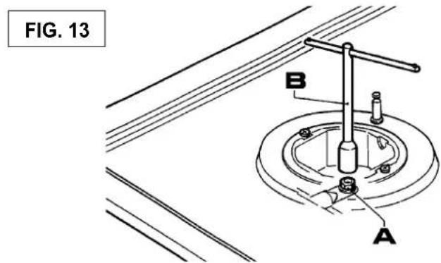
The burners can be adapted to suited different types of gas by fitting the nozzles that correspond to the gas used. To do this, it is necessary to remove the burner heads and use a straight key "B", to unscrew the nozzle "A" (see fig. 13) and replace it with a nozzle corresponding to the gas used.
We advise you to block the nozzle tightly.
After making these replacements, the technician must regulate the burners as described in paragraph 9, seal any regulation or pre-regulation organs and apply the label corresponding to the new gas regulation carried out on the appliance in place of that previously applied. This label is contained in the spare nozzle bag.
For the ease of the fitter, we have prepared a table indicating the flow capacities, the heat capacities of the burners, the diameter of the nozzles and the working pressure for the various types of gas.

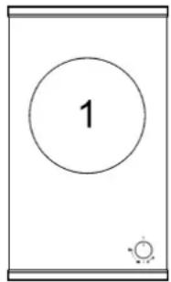
TRANSFORMERS
ARRANGEMENT OF THE BURNERS
GWS3811.0ED
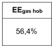
| EE_gas hob |
| 56,4% |
GKS3820.0ED
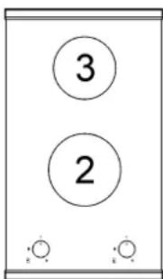
| EE_gas hob |
| 58,3% |
GKS9851.0ED
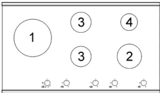
| EE_gas hob |
| 57,4% |
TABLE
| BURNERS | GAS | NORMAL PRESSURE mbar | NORMAL RATE | INJECTOR DIAMETER Max.10E mm | NOMINAL HEAT INPUT (W) | ||||
| No. | DESCRIPTION | g/h | l/h Min. | gas burner* | |||||
| 1 | DUAL total** | G 30 - BUTANE | 28 - 30 | 436 | 2 x 80 B + 46 B | 3500 | 6000 | 56,4% | |
| G 31 - PROPANE | 37 | 429 | 2 x 80 B + 46 B | 3500 | 6000 | ||||
| G 20 - NATURAL | 20 | 571 | 2 x 125 A + 71 A | 3500 | 6000 | ||||
| DUAL central | G 30 - BUTANE | 28 - 30 | 58 | 46 B | 400 | 800 | --- | ||
| G 31 - PROPANE | 37 | 57 | 46 B | 400 | 800 | ||||
| G 20 - NATURAL | 20 | 76 | 71 A | 400 | 800 | ||||
| 2 | Rapid | G 30 - BUTANE | 28 - 30 | 218 | 85 | 800 | 3000 | 60,1% | |
| G 31 - PROPANE | 37 | 214 | 85 | 800 | 3000 | ||||
| G 20 - NATURAL | 20 | 286 | 117 Y | 800 | 3000 | ||||
| 3 | Semirapid | G 30 - BUTANE | 28 - 30 | 127 | 68 | 550 | 1750 | 56,6% | |
| G 31 - PROPANE | 37 | 125 | 68 | 550 | 1750 | ||||
| G 20 - NATURAL | 20 | 167 | 98 Z | 550 | 1750 | ||||
| 4 | Auxiliary | G 30 - BUTANE | 28 - 30 | 73 | 51 | 450 | 1000 | N.A. | |
| G 31 - PROPANE | 37 | 71 | 51 | 450 | 1000 | ||||
| G 20 - NATURAL | 20 | 95 | 75 X | 450 | 1000 | ||||
*In accordance with Regulation No. 66/2014 EU measures for the implementation of Directive2009/125/EC, the performance (EEgas burner) was calculated according to EN 30-2-1 last review with the G20.
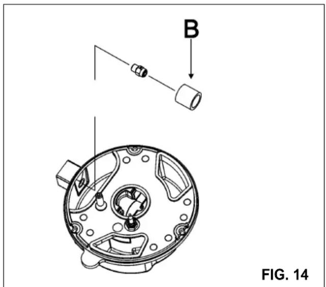
**Mount with bushing (B) if present (see Fig. 14).
TRANSFORMERS
ARRANGEMENT OF THE BURNERS
GMS7651.0E GMS9651.0E
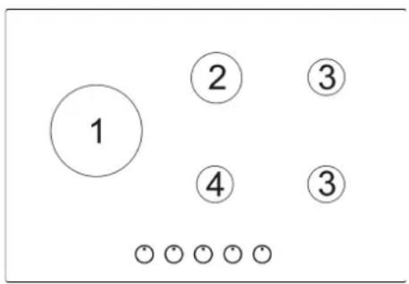
*In accordance with Regulation No. 66/2014 EU measures for the implementation of Directive2009/125/EC, the performance (EEgas burner) was calculated according to EN 30-2-1 last review with the G20.
**Mount with bushing (B) if present (see Fig. 14).



MAINTENANCE
POWER CABLE TYPES AND SECTIONS
| TYPE OF HOB | TYPE OF CABLE | CABLEMONOPHASE |
| Gas hob H05 RR - F Section 3 x 0.75 mm | ^2 | |
CAUTION!!!
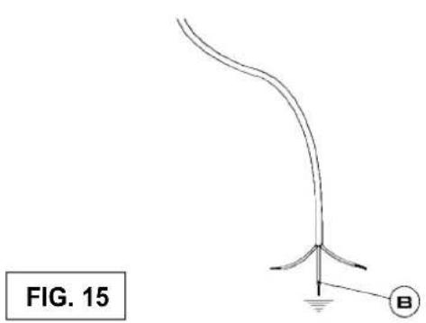
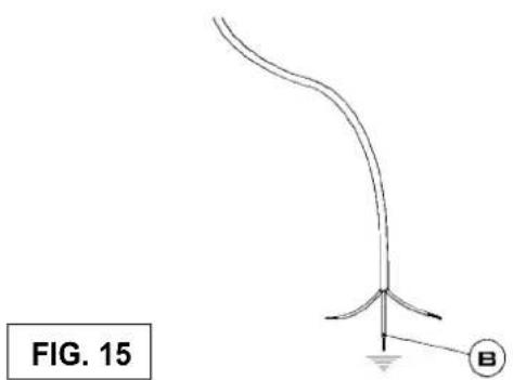
When replacing the power cable, the fitter must keep the earth conductor "B" longer than the phase conductor (fig. 15) and must also observe the warnings indicated in paragraph 8.
WARNING: MAINTENANCE MUST ONLY BE PERFORMED BY AUTHORISED PERSONS.
In case of failure or cut in the cable, please move away from the cable and do not touch it. Moreover the device must be unplugged and not switched on. Call the nearest authorized service center to fix the problem.
TECHNICAL ASSISTANCE AND SPARES
Before leaving the factory, this appliance was tested and regulated by specially qualified experts in order to guarantee the best operating results.
The original spare parts can be found only in our Technical Assistance Centres and authorised shops.
Every repair or regulation operation which should become subsequently necessary must be carried out with the utmost care and attention by qualified personnel.
This is why we recommend that you always contact the Dealer who sold the appliance or our nearest Assistance Centre, specifying the brand, the model, the serial number and the type of problem affecting your appliance. The pertinent data is stamped on the label applied to the underside of the appliance and on the label applied to the packing box.
This information enables the technical assistance department to acquire the appropriate spare parts and consequently guarantee prompt and targeted intervention. We recommend that you write this data in the spaces below and keep it to hand at all times:
BRAND:
MODEL:
SERIES:

TECHNICAL DATA PRINTED ON THE LABEL
GWS3811.0ED
CATEGORY = I_2H_3+
G 30 - BUTANE = 28 - 30 mbar
G 31 - PROPANE = 37 mbar
G 20 - NATURAL = 20 mbar
Σ Qn Gas Natural = 6.0 kW
Σ Qn GPL = 436 g/h (G30)
Σ Qn GPL = 429 g/h (G31)
VOLTAGE = 220 - 240 V\~
FREQUENCY = 50/60 Hz
GKS3820.0ED
CATEGORY = I_2H_3+
G 30 - BUTANE = 28 - 30 mbar
G 31 - PROPANE = 37 mbar
G 20 - NATURAL = 20 mbar
Σ Qn Gas Natural = 4.75 kW
Σ Qn GPL = 345 g/h (G30)
Σ Qn GPL = 339 g/h (G31)
VOLTAGE = 220 - 240 V\~
FREQUENCY = 50/60 Hz
GKS9851.0ED
CATEGORY = I_2H_3+
G 30 - BUTANE = 28 - 30 mbar
G 31 - PROPANE = 37 mbar
G 20 - NATURAL = 20 mbar
Σ Qn Gas Naturale = 13.5 kW
Σ Qn GPL = 981 g/h (G30)
Σ Qn GPL = 964 g/h (G31)
VOLTAGE = 220 - 240 V\~
FREQUENCY = 50/60 Hz
GMS7651.0E
$$ \text { CATEGORY } = \mathrm{I} _ {2 \mathrm{H} 3 +} $$
G 30 - BUTANE = 28 - 30 mbar
G 31 - PROPANE = 37 mbar
G 20 - NATURAL = 20 mbar
Σ Qn Gas Naturale = 11.5 kW
Σ Qn GPL = 545 g/h (G30)
Σ Qn GPL = 536 g/h (G31)
VOLTAGE = 220 - 240 V\~
FREQUENCY = 50/60 Hz
GMS9651.0E
$$ \text { CATEGORY } = \mathrm{I} _ {2} \mathrm{H} _ {3 +} $$
G 30 - BUTANE = 28 - 30 mbar
G 31 - PROPANE = 37 mbar
G 20 - NATURAL = 20 mbar
Σ Qn GPL = 12.25 kW
Σ Qn Gas Natural = 12.50 kW
Σ Qn GPL = 891 (G30)
Σ Qn GPL = 875 (G31)
VOLTAGE = 220 - 240 V\~
FREQUENCY = 50/60 Hz
This appliance is marked according to the European directive 2002/96/EC on Waste Electrical and Electronic Equipment (WEEE).
This guideline is the frame of a European-wide validity of return and recycling on Waste Electrical and Electronic Equipment.



ATTENZIONE:
Spegnimento:
Σ Qn Gas Naturale = 6.0 kW
Σ Qn GPL = 436 g/h (G30)
Σ Qn GPL = 429 g/h (G31)
TENSIONE = 220 - 240 V \~
FREQUENZA = 50/60 Hz
GKS3820.0ED
CATEGORIA = IbH3+
Σ Qn Gas Naturale = 13.5 kW
Σ Qn GPL = 981 g/h (G30)
Σ Qn GPL = 964 g/h (G31)
TENSIONE = 220 - 240 V\~
FREQUENZA = 50/60 Hz
GMS7651.0E
CATEGORIA = I2H3+
Σ Qn Gas Naturale = 11.5 kW
Σ Qn GPL = 545 g/h (G30)
Σ Qn GPL = 536 g/h (G31)
TENSIONE = 220 - 240 V\~
FREQUENZA = 50/60 Hz
GMS9651.0E
CATEGORIA = Ib2H3+
Σ Qn Gas Naturale = 12.50 kW
Σ Qn GPL = 891 g/h (G30)
Σ Qn GPL = 875 g/h (G31)
TENSIONE = 220 - 240 V\~
FREQUENZA = 50/60 Hz
Σ Qn Gas Natural = 6.0 kW
Σ Qn GPL = 436 g/h (G30)
Σ Qn GPL = 429 g/h (G31)
Σ Qn Gas Natural = 4.75 kW
Σ Qn GPL = 345 g/h (G30)
Σ Qn GPL = 339 g/h (G31)
Σ Qn Gas Natural = 13.5 kW
Σ Qn GPL = 981 g/h (G30)
Σ Qn GPL = 964 g/h (G31)
Σ Qn Gas Natural = 11.5 kW
Σ Qn GPL = 545 g/h (G30)
Σ Qn GPL = 536 g/h (G31)
Σ Qn Gas Natural = 12.50 kW
Σ Qn GPL = 891 g/h (G30)
Σ Qn GPL = 875 g/h (G31)
natural_image
Simple circular diagram with a star, dots, and small symbols (no text or labels)Posição de saída máxima de gás
Position for maksimal gasmængde
Maksimal gasstyrke
Läge för max. Gasflöde
Kaasun maksimi syöttö
Pozycja dostarczania maksymalnej ilości gazu
Asend maksimaalse gaasikulu korral
Padėtis, kai duju sanaudos didžiausios
Stávoklis ar maksimálu gâzes patçriòu
Poloha maximálneho prívodu plynu
- Posição fechada
Lukket position
Lukket posisjon
Stängt läge
Kiinni-asento
Pozycja zamknięta
Suletud asend
Padėtis Uždaryta
Aizvçrtais stâvoklis
Zatvorená poloha
Posição de saída mínima de gás
Position for minimum gasmængde
Minimal gasstyrke
Läge för min. gasflöde
Kaasun minimi syöttö
Pozycja dostarczania minimalnej ilości gazu
Asend minimaalse gaasikulu korral
Padėtis, kai dujų sąnaudos mažiausios
Stâvoklis ar minimâlu gâzes patçriòu
Poloha minimálneho prívodu plynu
FIG. 1
natural_image
Two line drawings of a gas stove with heating elements, no text or symbols presentFIG. 2

(*) ENTRADA DE AR: VEJA O CAPÍTULO INSTALAÇÃO (PARÁGRAFOS 5 E 6)
(*) LUFTINDSUGNING: SE KAPITEL INSTALLATION (PUNKT 5 OG 6)
(*) LUFTINNGANG: SE KAPITTELET INSTALLASJON (AVSNITT 5 OG 6)
(*) LUFTINLOPP: SE AVSNITTET ANGÄENDE INSTALLATION (AVSNITT 5 OCH 6)
(*) ILMAN SISÄÄNTULO: KS. ASENNUSLUKU (KAPPALE 5 JA 6)
(*) WLOT POWIETRZA: PATRZ CZEŚĆ DOTYCZĄCA INSTALACJI ( rozdział 5 i 6)
(*) ÔHU JUURDEVOOL: VT PEATÜKKI PAIGALDAMINE (PARAGRAHVID 5 JA 6)
(*) ORO TIEKIMAS: ŽR. SKYRIŲ „IRENGIMAS“ (SKILTYS 5 IR 6)
(*) GAISA PIEKLÜVE: SKAT. NODALU UZSTÄDİŞANA (PARAGRÄFI 5 UN 6)
(*) VSTOP ZRAKA: POGLEJ POGLAVJE O INSTALACIJI (ODDELKA 5 IN 6)
LIMPEZA - RENG∅RING - RENGJ∅RING - RENGÖRING - PUHDISTUS CZYSZCZENIE - PUHASTUS - CLEANINGTÎRΊANA - ČIŠČENJE
natural_image
Hand using a tool to adjust or install a mechanical component on a circular base (no text or symbols visible)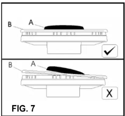
INSTALAÇÃO - INSTALLATION - INSTALLASJON - INSTALLATION - AS INSTALACJA - PAIGALDAMINE - İRENGIMAS - ZSTÄDİŞANA INSTALAC
| A B C D E F | |||||||
| GWS3811.0ED - GKS3820.0ED | 1F - 2F (30) | 282 | 473 | 63.5 | 63.5 | 300 | Min. 70 mm |
| GKS9851.0ED | 5F (90) | 833 | 473 | 63.5 | 63.5 | 300 | Min. 70 mm |
| GMS7651.0E | 5F (70) | 553 | 473 | 63.5 | 63.5 | 173.5 | Min. 70 mm |
| GMS9651.0E | 5F (90) | 833 | 475 | 62.5 | 62.5 | 300 | Min. 70 mm |
MEDIDAS A RESPEITAR (mm)
MÅL SOM SKAL OVERHOLDES (i mm)
MÅL SOM MÅ RESPEKTERES (i mm)
MÄTT SOM SKA RESPEKTERAS (i mm)
NOUDATETTAVAT MITAT (mm)
ODLEGŁOŚCI JAKENALEŻYZACHOWAĆ podane (w mm)
MÕÕTMED, MILLEST TULEB KINNI IDADA (ø mm)
REIKIAMI DYDŽIAI (mm)
IZMĚRI IEVĚROŠANAI (mm)
MERE, KATERE MORATE SPOŠTOVATI (v mm)
GMS7651.0E - GMS9651.0E
natural_image
Technical line drawing of a mechanical component with mounting holes and a labeled section E (no text or symbols beyond label)GWS3811.0ED-GKS3820.0ED-GKS9851.0ED
natural_image
Close-up of a metal panel with a circular component and a labeled point 'E' (no readable text or symbols beyond label)FIG. 10
INSTALAÇÃO - INSTALLATION - INSTALLASJON - INSTALLATION - AS INSTALACJA - PAIGALDAMINE - İRENGIMAS - ZSTÄDİŞANA INSTALAC
GMS7651.0E - GMS9651.0E
GWS3811.0ED-GKS3820.0ED-GKS9851.0ED
REGULAÇÕES - INDSTILLINGER - REGULERING - REGLERINGAR - SÄÄDÖT - REGULACJA - SEADISTUSED - REGULIAVIMAS - PIELÃGOŠANA - UREJANJE
TRANSFORMAÇÕES - ÆENDRINGER - ENDRINGER - OMVANDLINGAR MUUTOKSET - PRZERÓBKI - ÜMBERSEADISTAMINE - KONVERTUOTI - PÄRKÄRTOŠANA - SPREMEMBE
natural_image
Diagram of a curved structure with labeled point B, no text or symbols presentDADOS TÉCNICOS DA REGULAÇÃO DE GÁS DO APARELHO
TEKNISKE DATA FOR INDSTILLING AF APPARATETS GASTYPE
TEKNISKE DATA FOR REGULERING AV APPARATET
TEKNISKA DATA SOM ANGES PÅ MÄRKETIKETTEN
TEKNISET TIEDOT LAITTEEN KAASUN SÄÄTÖÖN
DANE TECHNICZNE DOTYCZĄCE REGULACJI INTENSYWNOŚCI GAZU
GAASIVARUSTUSE REGULEERIMISEKS VAJALIKUD TEHNILISED ANDMED
DUJU REGULIAVIMO TECHNINIAI DUOMENYS
GĀZES REGULĒŠANAS TEHNISKIE PARAMETRI
TEHNIČNI PODATKI PLINSKE URAVNANOSTI NAPRAVE
| Este aparelho pode ser instalado e funcionar somente em locais permanentemente ventilados, segundo as normas envigor. Para fazer a ligação à rede de distribuição do gás, utilizar tubos metálicos rígidos ou tubos metálicos flexíveis em conformidade com a norma envigor. Consultar o manual de instruções antes de instalar este aparelho.Este aparelho foi regulado para funcionar com: PTG20 (2H) 20 mbar | Dette apparat må udelukkende installeres og tages i brug i rum med permanent udluftning iht gældende regler.Ved tilslutning til gasforsyningen skal man bruge metalrør eller metalslanger iht. gældende regler.Læs brugsanvisningen inden dette apparat installeres.Dette apparat er beregnet til brug med:DKG20 (2H) 20 mbar | Dette apparat kan installeres og settes i funksjon kun i lokaler som er kontinuerlig ventilierti henhold til gjeldende normer.For á koble til gassnettet bruk harde metallslanger eller fleksible metallslanger i overensstemmelse med gjeldende normer.Se bruksanvisningen før du installerer dette apparat.Dette apparat er regulert for á fungere ved:NOG20 (2H) 20 mbar | Этот прибор должен быть установлен в соответствии с действующими положениями, действующими и используются только в помещениях, оборудованных достаточной вентиляцией.Обратитесь к руководству по эксплуатации перед началом установки или эксплуатации прибора.Для другого типа газа, работают, как описано в направлениях для установки и использования. RUG20 (2H) 20 mbar | Laite voidaan asentaa ja sitä voidaan käyttää vain pysyvästi tuuletetuissa tiloissa voimassa olevien normien mukaisesti.Litä se kaasuverkkoon jäykkien metalliputkien tai joustavien metalliletkujen avulla voimassa olevan normin mukaisesti.Tutustu käyttöohjeeseen ennen laitteen asennusta.Tämä laite on säädetty toimimaan: FIG20 (2H) 20 mbar |
| Denna utrustning ska endast installeras och användas i lokaler som är permanent ventilierade enligt gällande föreskrifter.Anslutningen till gasnätet ska göras med styva eller flexibla metallrör som överensstämmer med gällande standard.Konsultera bruksanvisningen innan denna utrustning installeras. | ||||
| To urządzenie może być zainstalowane i eksploatowane wyłącznie w pomieszczeniach stale wentylowanych, zgodnie z normami UNI 7129i7131.Aby podłączyć je do sieci dystrybucji gazu należy użyć metalowych przewodów sztywnych lub elastycznych, spełniających wymogi obowiązujących norm.Przed zainstalowaniem tego urządzenia należy przeczytać instrukcję.To urządzenie zostało ustawione do eksploatacji z gazem: PLG20 (II2E) 20 mbar | Käesoleva seadme paigaldamine ja kasutamine on lubatud ainult pideva ventilatsiooniga ruumides, mis vastavad kehtivatele normidele.Gaasimagistraaliga ühendamiseks tuleb kasutada elastseid või jaiku metalltorusid, mis vastavad kehtivatele nõuetele.Enne plidipladai paigaldamist tuleb käesolevas kasutusjuhendis esitatud juhised läbi lugeda.Antud plidiplaat on reguleeritud töötamiseks: EEG20 (2H) 20 mbar | Denna utrustning är reglerad för att fungera med:G20 (2H) 20 mbar SEŠi prietaisa jrengti ir juo naudotis galima tik patalpose nuolat ventiluojamose patalpose pagal galiojančiu normu reikalavimus.Pajungimui prie duju tinkdo reikia naudoti kietus metallinius vamzdžius arba lanksčias metalines žarnas, atitinkančias galiojančiu normu reikalavimus.Prieš pradedant montuoti kaitlente bütina perskaityi šiame vadove pateiktus nurodymus.Si kaitlente sureguliuota šiai duju rõšiai: LTG20 (2H) 20 mbar | Šis sadzīves tehnikas uzstādīšana un izmantošana ir atļauta tikai telpās ar pastāvīgu ventilāciju saskaņa ar esošo normu prasībām.Lai pieslēgtos gāzes tiklam, ir jāizmanto stingrās vai lokanas metāla caurules, kuras atbilst esošo normu prasībām.Pirms veikt vārīšanas panela uzstādīšanu, ir nepieciešams izlasīt instrukcijas sajā lietošanas pamācībā.Ši vārīšanasviismai inoregulēta darbam ar: LVG20 (2H) 20 mbar | Ta naprava se lahko priključi in deluje samo v prostorih, ki so stalno zračeni, kot je v skladu z normativi UNI 7129 in 7131.Za priključitev na plinsko omrežje uporabite kovinske negibljive ali gibljive cevi, ki so v skladu z normativi UNI EN 14800.Pred priključitvijo naprave preberite ta priročnik.Ta naprava je uravnana za delovanje z: SIG20 (2H) 20 mbar |

Σ Qn Gás Natural = 6.0 kW
Σ Qn Butano = 436 g/h (G30)
Σ Qn Propano = 429 g/h (G31)
Σ Qn Gás Natural = 13.5 kW
Σ Qn Butano = 981 g/h (G30)
Σ Qn Propano = 964 g/h (G31)
Σ Qn Gás Natural = 11.50 kW
Σ Qn Butano = 836 g/h (G30)
Σ Qn Propano = 821 g/h (G31)
Σ Qn Gás Natural = 12.50 kW
Σ Qn Butano = 12.25 kW
Σ Qn Butano = 891 (G30)
Σ Qn Propano = 875 (G31)
3) INSTALLATION AF KOGEPLADEN
INSTALLATIONSFÖRESKRIFTER
BRÄNNARNAS PLACERING
GWS3811.0ED
GKS3820.0ED
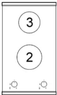
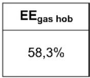
GKS9851.0ED
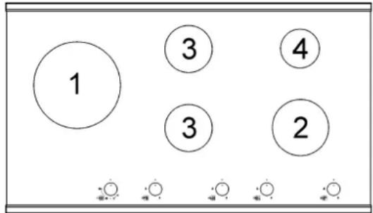
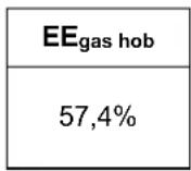
TABELL
| BRÄNNARE | GAS | DRIFTTRYCKmbar | TERMISKKAPACITET | MUNSTYCKETSDIAMETER1/102mm | TERMISKKAPACITET (W) | ||||
| No. | BENÄMNING | g/h | l/h Min. | gas burner* | |||||
| 1 | DUAL total** | G 30 - BUTANG 31 - PROPANG 20 - NATURGAS | 303020 | 436429 | 571 | 2 x 80 B + 46 B2 x 80 B + 46 B2 x 125 A + 71 A | 350035003500 | 600060006000 | 56,4% |
| DUAL central | G 30 - BUTANG 31 - PROPANG 20 - NATURGAS | 303020 | 5857 | 76 | 46 B46 B71 A | 400400400 | 800800800 | N.A. | |
| 2 | SNABB | G 30 - BUTANG 31 - PROPANG 20 - NATURGAS | 303020 | 218214 | 286 | 8585117 Y | 800800800 | 300030003000 | 60,1% |
| 3 | HALVSNABBBAKRE | G 30 - BUTANG 31 - PROPANG 20 - NATURGAS | 303020 | 127125 | 167 | 686898 Z | 550550550 | 175017501750 | 56,6% |
| 4 | EXTRA | G 30 - BUTANG 31 - PROPANG 20 - NATURGAS | 303020 | 7371 | 95 | 515175 X | 450450450 | 100010001000 | N.A. |
BRÄNNARNAS PLACERING
GMS7651.0E
Gaszenie:
Σ Qn 2E (G20) = 6.0 kW
Σ Qn 3B/P (G30-G31) = 436 g/h (G30)
NAPIĘCIE = 220 - 240 V \~
CZESTOTLIWOŚĆ = 50/60 Hz
GKS3820.0ED
Kategoria = ||2E3B/P
3B/P (G30-G31) = 37 mbar
2E (G20) = 20 mbarr
Σ Qn 2E (G20) = 4.75 kW
Σ Qn 3B/P (G30-G31) = 345 g/h (G30)
NAPIĘCIE = 220 - 240 V \~
CZESTOTLIWOŚĆ = 50/60 Hz
GKS9851.0ED
Kategoria = ||2E3B/P
3B/P (G30-G31) = 37 mbar
2E (G20) = 20 mbar
Σ Qn 2E (G20) = 13.5 kW
Σ Qn 3B/P (G30-G31) = 981 g/h (G30)
NAPIECIE = 220 - 240 V \~
CZESTOTLIWOŚĆ = 50/60 Hz
GMS7651.0E
Kategoria = ||2E3B/P
3B/P (G30-G31) = 37 mbar
2E (G20) = 20 mbar
Σ Qn 2E (G20) = 11.50 kW
Σ Qn 3B/P (G30-G31) = 836 g/h (G30)
NAPIECIE = 220 - 240 V \~
CZĘSTOTLIWOŚĆ = 50/60 Hz
GMS9651.0E
Kategoria = I _2E3B/P
3B/P (G30-G31) = 37 mbar
2E (G20) = 20 mbar
Σ Qn 2E (G20) 12.50 kW
Σ Qn 3B/P (G30-G31) = 12.25 kW
NAPIECIE = 220 - 240 V \~
CZESTOTLIWOŚĆ = 50/60 Hz
1) TavalISED PÕLETID
HOIATUS! HOOLDUST TOHIB TEHA AINULT VOLITATUD ISIK.
ANDMEPLAADIL (ETIKETIL) ESITATUD TEHNILISED ANDMED
GWS3811.0ED
KATEGOORIA = 2H3B/P
G 30 - BUTAAN = 30 mbar
G 31 - PROPAAN = 30 mbar
Σ Qn Maagaas = 6.0 kW
Σ Qn Butaan = 436 g/h (G30)
Σ Qn Propaan = 429 g/h (G31)
PINGE = 220 - 240 V \~
SAGEDUS = 50/60 Hz
GKS3820.0ED
KATEGOORIA = 1H3B/P
G 30 - BUTAAN = 30 mbar
G 31 - PROPAAN = 30 mbar
Σ Qn Maagaas = 13.5 kW
Σ Qn Butaan = 981 g/h (G30)
Σ Qn Propaan = 964 g/h (G31)
PINGE = 220 - 240 V \~
SAGEDUS = 50/60 Hz
GMS7651.0E
KATEGOORIA = 2H3B/P
G 30 - BUTAAN = 30 mbar
G 31 - PROPAAN = 30 mbar
Σ Qn Maagaas = 12.50 kW
Σ Qn Butaan = 12.25 kW
Σ Qn Butaan = 891 (G30)
Σ Qn Propaan = 875 (G31)
PINGE = 220 - 240 V \~
SAGEDUS = 50/60 Hz
EE
TEHNOHOOLDUS JA VARUOSAD
FIG. 14
LV
PĀRKĀRTOŠANA
DEGLU RAKSTUROJUMI
GWS3811.0ED
| EE_gas hob |
| 56,4% |
GKS3820.0ED
| EE_gas hob |
| 58,3% |
GKS9851.0ED
| EE_gas hob |
| 57,4% |
TABULA
| DEGLI | GAZE | DARBA SPIEDIENS mbar | SILTUMA PATÈRINŠ | SPRAUSLAS DIAMETRS 1/100 mm | TERMISK EFFEKT (W) | ||||
| No. | APRAKSTS | g/h | l/h Min. | gas burner* | |||||
| 1 | DUAL Kopā** | G30 - BUTÄNS | 30 | 436 | 2 x 80 B + 46 B | 3500 | 6000 | 56,4% | |
| G31 - PROPÄNS | 30 | 429 | 2 x 80 B + 46 B | 3500 | 6000 | ||||
| G20 - DABASGAZE | 20 | 571 | 2 x 125 A + 71 A | 3500 | 6000 | ||||
| DUAL galvenais | G30 - BUTÄNS | 30 | 58 | 46 B | 400 | 800 | --- | ||
| G31 - PROPÄNS | 30 | 57 | 46 B | 400 | 800 | ||||
| G20 - DABASGAZE | 20 | 76 | 71 A | 400 | 800 | ||||
| 2 | ÄTRUMDEGLIS | G30 - BUTÄNS | 30 | 218 | 85 | 800 | 3000 | 60,1% | |
| G31 - PROPÄNS | 30 | 214 | 85 | 800 | 3000 | ||||
| G20 - DABASGAZE | 20 | 286 | 117 Y | 800 | 3000 | ||||
| 3 | PUSÄTRAIS | G30 - BUTÄNS | 30 | 127 | 68 | 550 | 1750 | 56,6% | |
| G31 - PROPÄNS | 30 | 125 | 68 | 550 | 1750 | ||||
| G20 - DABASGAZE | 20 | 167 | 98 Z | 550 | 1750 | ||||
| 4 | PALIGDEGLIS | G30 - BUTÄNS | 30 | 73 | 51 | 450 | 1000 | N.A. | |
| G31 - PROPÄNS | 30 | 71 | 51 | 450 | 1000 | ||||
| G20 - DABASGAZE | 20 | 95 | 75 X | 450 | 1000 | ||||
FREKVENCE = 50/60 Hz
GKS3820.0ED
KATEGORIJA = II2H3B/P
G30 - BUTÄNS= 30 mbar
G31 - PROPÃNS = 30 mbar
G20-DABAS GÄZE=20mbar
Σ Qn DABAS GÄZE = 4.75 kW
Σ Qn BUTÄNS = 345 g/h (G30)
Σ Qn PROPÄNS = 339 g/h (G31)
SPRIEGUMS = 220 - 240 V \~
FREKVENCE = 50/60 Hz
GKS9851.0ED
KATEGORIJA = II2H3B/P
G 30 - BUTÄNS= 30 mbar
G 31 - PROPÄNS = 30 mbar
G 20 - DABAS GÃZE = 20 mbar
Σ Qn DABAS GÄZE = 13.5 kW
Σ Qn BUTÄNS = 981 g/h (G30)
Σ Qn PROPÄNS = 964 g/h (G31)
SPRIEGUMS = 220 - 240 V \~
FREKVENCE = 50/60 Hz
GMS7651.0E
KATEGORIJA = II2H3B/P
G 30 - BUTÄNS = 30 mbar
G 31 - PROPÄNS = 30 mbar
G 20 - DABAS GÃZE = 20 mbar
Σ Qn DABAS GÄZE = 11.50 kW
Σ Qn BUTÄNS = 836 g/h (G30)
Σ Qn PROPÄNS = 821 g/h (G31)
SPRIEGUMS = 220 - 240 V \~
FREKVENCE = 50/60 Hz
GMS9651.0E
KATEGORIJA = II2H3B/P
G 30 - BUTÄNS = 30 mbar
G 31 - PROPÃNS = 30 mbar
G 20 - DABAS GÃZE = 20 mbar
Σ Qn BUTÄNS = 12.25 kW
Σ Qn DABAS GÄZEr = 12.50 kW
Σ Qn BUTĀNS = 891 (G30)
Σ Qn PROPÄNS = 875 (G31)
SPRIEGUMS = 220 - 240 V \~
FREKVENCE = 50/60 Hz
GWS3811.0ED - GKS3820.0ED - GKS9851.0ED

natural_image
Simple line drawing of a circular object with vertical bars and three small icons below (no text or symbols)
закрытом
положении
natural_image
Simple line drawing of a cooking pot with a wavy base and two handles (no text or symbols)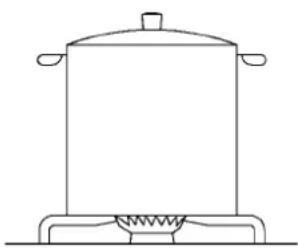
natural_image
Line drawing of a cooking pot on a stove (no text or symbols)РИС. 2
ПРАВИЛА ПОЛЬЗОВАНИЯ
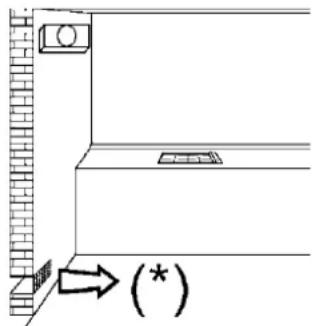
РИС. 5
natural_image
Line drawing of a hand using a tool to clean or inspect a circular component (no text or symbols)РИС. 6
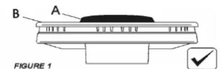
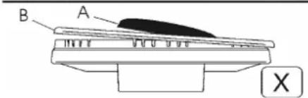
РИС. 7
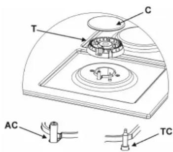
РИС. 8
natural_image
Technical line drawing of a mechanical component with labeled point E and directional arrow (no text or symbols beyond label)РИС·10
natural_image
Close-up of a mechanical component with a circular feature and labeled point E, no readable text or symbols present.GWS3811.0ED - GKS9851.0ED
- GKS3820.0ED
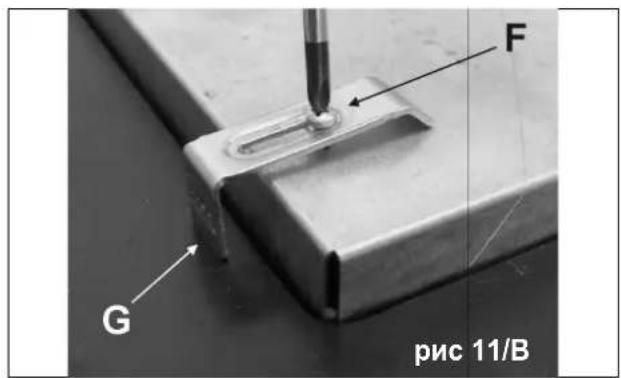
РИС. А
РИС. С
GWS3811.0ED K06-180130/01
GKS3820.0ED K06-180129/01
GKS9851.0ED K06-180128/01
GMS7651.0E K06-180024/01
GMS9651.0E K06-180023/01
Küppersbusch
- REINIGUNG - NETTOYAGE - REINIGING - KAΘΑΡΙΣΜΟΣ - TEMİZLEME ČIŠTĚNÍ - ČISTENIE - CLEANING - PULIZIA - LIMPIEZA
- INSTALLATION - INSTALLATIE - EΓΚΑΤΑΣΤΑΣΗ - MONTAJ - INSTALAC INŠTALÁCIA - INSTALLATION - INSTALLAZIONE - INSTALACIÓN
- EINSTELLUNGSARBEITEN - REGLAGES - REGELINGEN P'YOMIŞH - AYARLAMALAR -SEŘÍZENÍ - NASTAVENIA INSTALLATION - REGOLAZIONI - REGULACIONES
- UMÄNDERUNGEN - TRANSFORMATIONS - VERANDERINGEN METATPOΠΕΣ - ÇEVİRMELER - PŘEMĚNA - VIMENY CONVERSION - TRASFORMAZIONI - TRANSFORMACIONES
- ATTENTION!
- GKS3820.0ED
- GKS9851.0ED
- GMS7651.0E
- GMS9651.0E
- BESCHRIJVING KOOKPLATEN
- TYPE: PCK 306090
- TYPE: PCZJ 6075 TYPE: PCZJ 90
- Kapatma:
- POKYNY DOLEŽITÉ PRE INSTALÁCIU
- DESCRIPTION OF HOBS
- USE
- 1) TRADITIONAL BURNERS
- - Manual ignition
- - Automatic electric ignition
- - Lighting burners fitted with a safety cut-off device
- How to use the burners
- 1/A) DUAL BURNERS
- LIGHTING AND USING THE "DUAL" BURNER Stand the pan on the burner before lighting.
- WARNINGS:
- WARNINGS AND RECOMMENDATIONS FOR THE USER:
- CLEANING
- IMPORTANT:
- 2) GAS HOB CERAMIC
- CAUTION:
- INSTALLATION
- TECHNICAL INFORMATION FOR THE INSTALLER
- 3) INSTALLING THE HOB
- IMPORTANT!
- 4) FITTING THE HOB
- IMPORTANT INSTALLATION INSTRUCTIONS
- 5) ROOM VENTILATION
- 6) LOCATION AND AERATION
- 7) GAS CONNECTION
- WARNING:
- GAS PRESSURE TEST
- REGULATION
- 9) VALVES
- THE BURNERS DO NOT REQUIRE ANY REGULATION OF THE PRIMARY AIR.
- 10) REPLACING NOZZLES
- TRANSFORMERS
- ARRANGEMENT OF THE BURNERS
- MAINTENANCE
- CAUTION!!!
- TECHNICAL ASSISTANCE AND SPARES
- TECHNICAL DATA PRINTED ON THE LABEL
- GWS3811.0ED
- ATTENZIONE:
- Spegnimento:
- LIMPEZA - RENG∅RING - RENGJ∅RING - RENGÖRING - PUHDISTUS CZYSZCZENIE - PUHASTUS - CLEANINGTÎRΊANA - ČIŠČENJE
- INSTALAÇÃO - INSTALLATION - INSTALLASJON - INSTALLATION - AS INSTALACJA - PAIGALDAMINE - İRENGIMAS - ZSTÄDİŞANA INSTALAC
- REGULAÇÕES - INDSTILLINGER - REGULERING - REGLERINGAR - SÄÄDÖT - REGULACJA - SEADISTUSED - REGULIAVIMAS - PIELÃGOŠANA - UREJANJE
- TRANSFORMAÇÕES - ÆENDRINGER - ENDRINGER - OMVANDLINGAR MUUTOKSET - PRZERÓBKI - ÜMBERSEADISTAMINE - KONVERTUOTI - PÄRKÄRTOŠANA - SPREMEMBE
- DADOS TÉCNICOS DA REGULAÇÃO DE GÁS DO APARELHO
- TEKNISKE DATA FOR INDSTILLING AF APPARATETS GASTYPE
- TEKNISKE DATA FOR REGULERING AV APPARATET
- TEKNISKA DATA SOM ANGES PÅ MÄRKETIKETTEN
- TEKNISET TIEDOT LAITTEEN KAASUN SÄÄTÖÖN
- DANE TECHNICZNE DOTYCZĄCE REGULACJI INTENSYWNOŚCI GAZU
- GAASIVARUSTUSE REGULEERIMISEKS VAJALIKUD TEHNILISED ANDMED
- 3) INSTALLATION AF KOGEPLADEN
- INSTALLATIONSFÖRESKRIFTER
- BRÄNNARNAS PLACERING
- Gaszenie:
- 1) TavalISED PÕLETID
- ANDMEPLAADIL (ETIKETIL) ESITATUD TEHNILISED ANDMED
- TEHNOHOOLDUS JA VARUOSAD
- PĀRKĀRTOŠANA
- DEGLU RAKSTUROJUMI
- ПРАВИЛА ПОЛЬЗОВАНИЯ
- Küppersbusch
Brand : Küppersbusch
Model : GKS3820.0ED
Category : Hob