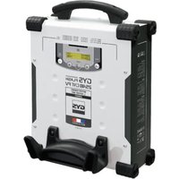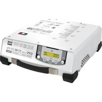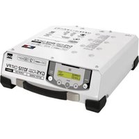
Gysflash 107.24 CNT FV - Welding machine GYS - Free user manual and instructions
Find the device manual for free Gysflash 107.24 CNT FV GYS in PDF.


User questions about Gysflash 107.24 CNT FV GYS
0 question about this device. Answer the ones you know or ask your own.
Ask a new question about this device
Download the instructions for your Welding machine in PDF format for free! Find your manual Gysflash 107.24 CNT FV - GYS and take your electronic device back in hand. On this page are published all the documents necessary for the use of your device. Gysflash 107.24 CNT FV by GYS.
USER MANUAL Gysflash 107.24 CNT FV GYS
natural_image
Technical line drawing of a mechanical device with heat exchangers and a central panel (no text or symbols)| FR | 02-15 / 100-104 |
| EN | 16-29 / 100-104 |
| DE | 30-43 / 100-104 |
| ES | 44-57 / 100-104 |
| RU | 58-71 / 100-104 |
| NL | 72-86 / 100-104 |
| IT | 87-100 / 100-104 |
GYSFLASH 107.24 CNT FV
INSTRUCTIONS DE SÉCURITÉ


text_image
Diagram illustrating various electrical safety symbols and correct circuit conditions, including battery, eyeglasses, gloves, and circuit breakers.text_image
Auto - Detect 12.5v Chargeline
| Stage | U | I | | ----------------- | ---- | ---- | | Analyse | 0% | 0% | | Récupération | 0% | 0% | | Test | 10% | 0% | | Désulfatation | 10% | 0% | | Charge | 20% | 0% | | Absorption | 20% | 0% | | Refresh (if option active) | 95% | 0% | | Maintien de charge | 100% | 0% |Étape 1 : Analyse
line
| Phase | U (voltage) | I (current) | | ------------------------- | ----------- | ----------- | | 12 | High | Low | | 5 | Medium | Low | | 6 | Low | Low |Étape 1 : Analyse
natural_image
Pure icon grid with magnifying glass and document symbol, no text or labelsnatural_image
Diagram of a mechanical clamp or spring with attached wires and a circular button (no text or symbols)OK NOK NOK
natural_image
Diagram of a mechanical or electrical component with curved and straight sections, no visible text or symbols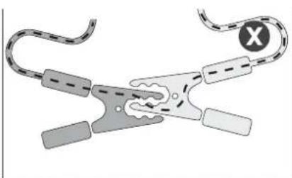
natural_image
Diagram of a mechanical clamp or tool with curved and straight ends, no text or symbols presenttext_image
Icon set grid with document, upload, download, and upload icons in a rowtext_image
Multi-Charger OFF Master + 1 Slave Master + 2 Slaves Master + 3 SlavesThis manual contains safety and operating instructions. Please read it carefully before using the device for the first time and keep it for future reference. This machine should only be used for charging or power supply operations specified within the limits indicated on the machine and in the instruction manual. The operator must observe the safety precautions. In case of improper or unsafe use, the manufacturer cannot be held liable.
The device is destined to be used indoors. Must not be exposed to the rain.
This unit can be used by children aged 8 or over and by people with reduced physical, sensory or mental capabilities or lack of experience or knowledge, if they are properly monitored or if instructions for using the equipment have safely been read and potential risks understood. Children must not play with the product. Cleaning and maintenance should not be performed by an unsupervised child.
Do not use to charge domestic batteries or non rechargeable batteries.
Do not use the charger if the mains cable or plug is damaged.
Do not use the device if the charging cable appears to be damaged or assembled incorrectly in order to avoid any risk of short circuiting the battery.
Never use on a frozen or damaged battery.
Do not cover the device.
Do not place the unit near a heat source or expose to prolonged high temperatures (above 60^ C).
Do not obstruct the cooling vents.
The operating mode of the automatic charger and the restrictions applicable to its use are explained later in this manual.
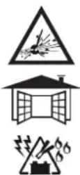
Fire and explosion risks!
- A battery can emit explosive gases when on charge.
- During the charge, the battery must be placed in a well ventilated area.
- Avoid flames and sparks.
- Protect the electrical contact surfaces of the battery against short circuits.
Do not leave a charging battery unattended for a long time.

Risk of acid dispersion!


- Wear protective goggles and gloves.

- In case of contact with the eyes or the skin, rinse immediately with water and see a medical doctor as soon as possible.
Connection / disconnection :
- Disconnect the power supply before plugging or unplugging the connections to/from the battery.
- Always ensure the Red clamp is connected to the «+» battery terminal first. If it is necessary to connect the black clamp to the vehicle chassis, make sure it is a safe distance from the battery and the fuel line. The charger must be connected to the mains.
- After charging, disconnect the charger from the mains, then disconnect the negative clamp from the car body and then disconnect the positive clamp from the battery, in this order.

Connection :
- The charger must be connected to an earthed power supply.
- The connection to the power supply must be carried out in compliance with national standards.

Maintenance :
- If the power supply cable is damaged, the replacement cable must be obtained from the manufacturer or its service team.
- Maintenance should only be carried out by a qualified person.
- Warning ! Always disconnect from the mains before performing maintenance on the device.
- The device does not require any specific maintenance.
- If the internal fuse is melted, it must be replaced by the manufacturer (GYS dedicated sales service) or by an equally qualified person to prevent any accidents.
- Do not use solvents or any agressive cleaning products.

Regulations :
- The Machine is compliant with European directives.
- The declaration of conformity is available on our website.
• EAEC Conformity marking (Eurasian Economic Community). - Equipment in compliance with British requirements. The British Declaration of Conformity is available on our website (see home page).
• Equipment in conformity with Moroccan standards. - The declaration C_p (CMIM) of conformity is available on our website (see cover page).

Waste management:
- This product should be disposed of at an appropriate recycling facility. Do not throw away in a household bin.
GENERAL DESCRIPTION
Your GYSFLASH is a professional multifunctional charger with Inverter technology. Designed to support the batteries of demonstration vehicles or during the diagnostic work, it also guarantees an ideal quality of charge for the maintenance of the most advanced models. This charger can be fitted with cables up to 8 m long. Changing the charging cables requires recalibration (see page 24). It is considered a fixed device not a mobile product.
Your GYSFLASH is supplied with a software that includes 4 different modes to choose from:
- Charging mode: dedicated to the charging of lead-acid (sealed, liquid, AGM...) or lithium (LiFePO4) starter batteries.
- Power mode | Diag+ : Supplies the energy required during diagnostic work on the vehicle.
- Power mode | Showroom : Maintains the charge of the battery and supplies the energy required when using the consumers of a demonstration vehicle.
- Tester Mode: Used to check the state of the battery and test the vehicle starting system and alternator.
Your GYSFLASH is SMART!
The original features of your GYSFLASH can be extended by adding specific charging modes and profiles using the USB port and custom settings (see page 26).
Your GYSFLASH also offers the possibility to recover data from several hundred charging operations on your USB stick for analysis on a spreadsheet.
Additional modules (such as printer, Ethernet port, etc.) can also be connected to the charger via its dedicated module socket.
«Auto-Detect» function:
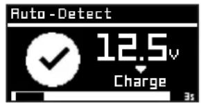
The Gysflash is equipped with the «Auto-Detect» function, which automatically starts a charge when a contact is detected at the output of the Gysflash (to activate/deactivate this function, see page 25).
text_image
Auto - Detect 12.5v Charge 3s- Connect the charger to the mains.
- Set the switch, located at the back of the charger, to «ON».
- Select the desired mode (Charge -> Supply -> Test).
To access the Configuration Menu, press the button.

MENU NAVIGATION AND MODE SETTINGS
| 1 Use the arrows to move around the menu or to change the value or condition of a parameter. |  |  |
| 2 Press the SELECT button to enter a sub-menu, select a parameter, or confirm a parameter value. |  | |
| 3 Press the back button to return to the previous menu (or sub-menu). |  | |
CHARGE MODE
text_image
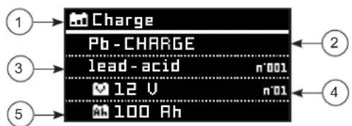
Charge Pb - CHARGE lead-acid n'001 12 V n'01 100 Ah1 - Mode
2 - Charging group
3 - Charging curve
4 - Nominal battery voltage
5 - Nominal battery capacity (curve permitting)
| Charge type: Profil Charging voltage | |||
| Pb-CHARGE | normal | 2.40 V/cell Lead batteries | of the types Gel, MF, EFB, SLA... |
| AGM | 2.45 V/cell | Most AGM lead-acid batteries including START and STOP.However, some AGM batteries require a lower voltage charge (Normal profile).Check the battery manual if in doubt. | |
| water | 2.45 V/cell Open liquid-type lead-acid batteries with cap. | ||
| Easy | 2.40 V/cell | Profile dedicated to lead batteries that automatically adapts the charging current according to the size of the battery.However, for maximum charge optimization, it is recommended, when possible,to use normal, AGM or liquid charge curves. | |
| Li-CHARGE LFP/LiFePO4 | 3.60 V/cell Lithium batteries type LFP (Lithium Ferro Phosphate) | ||
Starting the charge:
| Manual startTo start the charge, press the START/STOP button. |  | |
| 1 | Automatic start-upIf the AUTO-DETECT function is active, charging will start automatically after 3 seconds if a battery is present. |  |
| 2 | During charging, your GYSFLASH will indicate the percentage of progress of the charging cycle, voltage, current, amp-hours delivered, and time elapsed. | |
| 3 | Press the START/STOP button to stop the charge. |  |
Precautions:
When charging a vehicle, it is advisable to reduce the vehicle's power consumption to a minimum (turn off the lights, switch off the ignition, close the doors, etc.) so as not to disrupt the charging process.
Precaution: Check the electrolyte level for open batteries. If necessary, adjust levels before charging.
- Lead-acid charging curve:
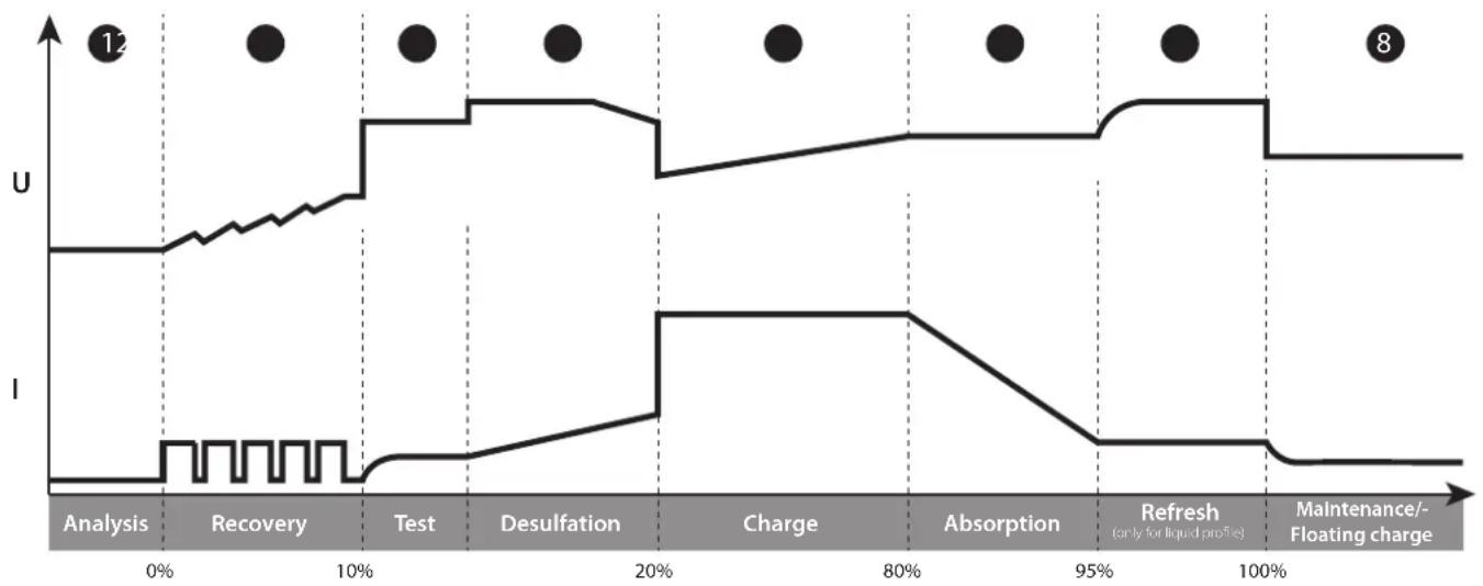
line
| Phase | U | I | | ---------------------- | ---- | ---- | | Analysis | 0% | 0% | | Recovery | 0% | 0% | | Test | 10% | 0% | | Desulfation | 10% | 0% | | Charge | 20% | 0% | | Absorption | 20% | 0% | | Refresh (only for liquid profile) | 95% | 0% | | Maintenance/Floating charge | 100% | 0% |Step 1 : Analysis
Analyses the state of the battery (charge level, polarity inversion, wrong battery...)
Step 2 : Recovery
Recovering damaged elements after deep and prolonged discharge.
Step 3 : Test
Sulfated battery test
Fast charge at maximum current to reach 80% charge level.
Step 6: Absorption
Constant voltage charge to reach 100% charge level.
Step 7: Refresh (only for liquid profile)
The charger supplies an additional current to create gas that will allow the electrolyte to be mixed and thus reconditioning the battery cells. During this phase, the battery may produce some water.
Step 8 : Maintenance/Floating charge
Maintains battery charge level at its maximum.
LFP Lithium charging curve:
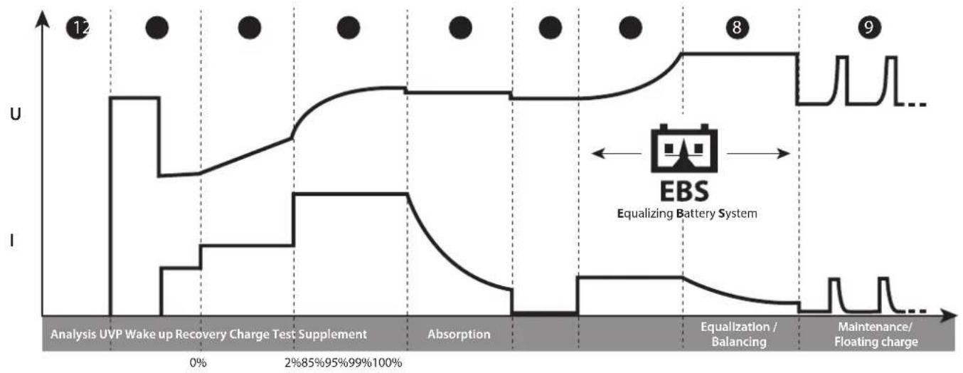
line
| Phase | U | I | |-------|----|----| | Analysis | 0 | 0 | | Wake up Recovery Charge Test Supplement | 12 | 0 | | Absorption | 0 | 0 | | Equalization / Balancing | 8 | 0 | | Maintenance/ Floating charge | 9 | 0 |Step 1 : Analysis
Analyses the state of the battery (charge level, polarity inversion, wrong battery...)
Step 2: UVP Wake up
Reactivates batteries in UVP protection (Under Voltage Protection)
Step 3: Recovery
Recovery algorithm following a deep discharge.
Step 4 : Charge
Maximum current fast charge to reach an 90% charge level.
Step 5: Absorption
Constant voltage charge to reach a 95% charge level.
Step 6 : Test
Charge conservation test.
Step 7 : Supplement
Reduce current charge to reach 100% charge level.
Step 8: Equalization / Balancing
Balancing the battery cells
Step 9: Maintenance/Floating charge
Maintain the battery charge level at its maximum.
POWER SUPPLY MODES: SHOWROOM / DIAG+
text_image
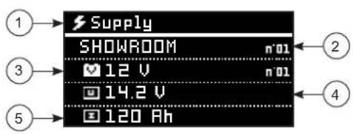
Supply SHOWROOM n°01 ✓ 12 V n°01 ☐ 14.2 V ☐ 120 Ah1- Mode
2- Cycle Supply
3- Nominal voltage (mode permitting)
4- Supply voltage
5- Supply current
- Starting the power supply:
text_image
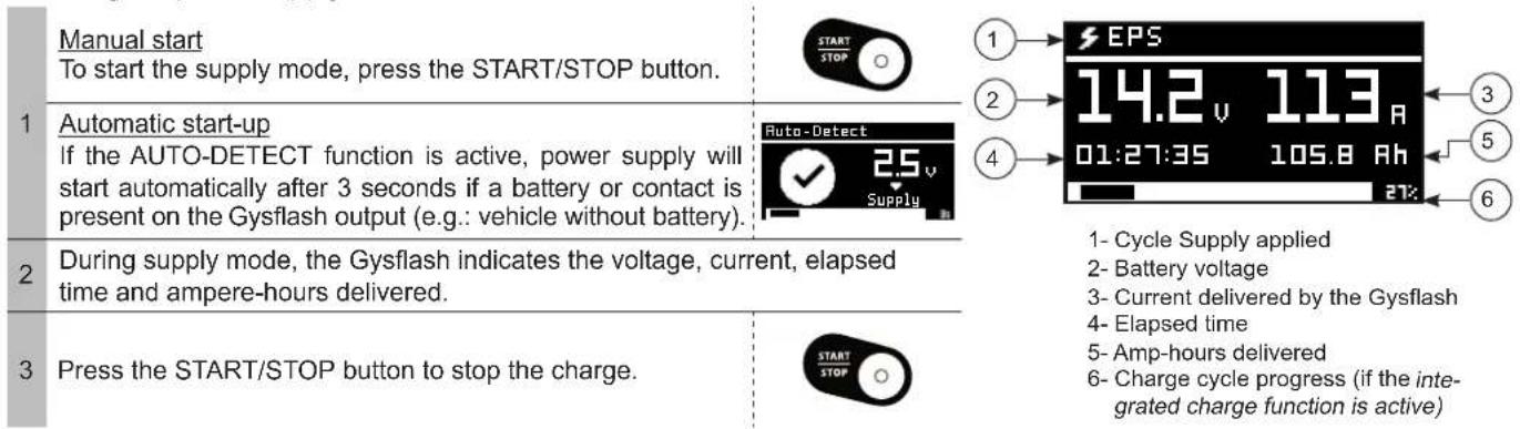
Manual start To start the supply mode, press the START/STOP button. 1 Automatic start-up If the AUTO-DETECT function is active, power supply will start automatically after 3 seconds if a battery or contact is present on the Gysflash output (e.g.: vehicle without battery). 2 During supply mode, the Gysflash indicates the voltage, current, elapsed time and ampere-hours delivered. 3 Press the START/STOP button to stop the charge. START STOP Auto-Detect 2.5 v Supply 1 EPS 14.2 v 113 R 01:27:35 105.8 Ah 27: 1- Cycle Supply applied 2- Battery voltage 3- Current delivered by the Gysflash 4- Elapsed time 5- Amp-hours delivered 6- Charge cycle progress (if the inte- grated charge function is active)Precautions :
When starting the mode, a current displayed above 10 A means that your battery is discharged. The device will start charging automatically Check that there is no electrical consumer on the vehicle. Wait until the current supplied drops below 10 A before starting any action on the vehicle (use of the vehicle's electrical accessories, diagnostic operation, etc.).
Features of the power modes:
| Mode | «No Battery» function | «Integrated charging» function | Abnormal undervoltage protection | Voltage adjustment |
| SHOWROOM | √ | √ | √ | 12 V models[6V 6.3 V - 7.2 V12V 12.7 V - 14.4 V24V 25.4 V - 28.8 V36V 38.1 V - 43.2 V48V 50.8 V - 57.6 V |
| DIAG+ | √ | 12 V models[12.7 V - 12.8 V24 V models16V 14.4 V - 17.2 V24V 25.4 V - 29.6 V36V 38.1 V - 44.4 V48V 50.8 V - 59.2 V |
- «No battery» function (not recommended):
This function allows you to use the SHOWROOM power mode when there is no battery. To do this, press the START/STOP button for 3 seconds. The «No battery mode» indication is displayed for 3 seconds before forcing the power supply.

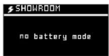

It is strongly recommended not to use the «no battery» function if a battery is present.
This function disables the «Integrated charging» function, as well as some of the protections such as abnormal undervoltage protection or disconnection detection.
In this configuration, reverse polarity can damage the vehicle electronics.
- «Integrated charging» function:
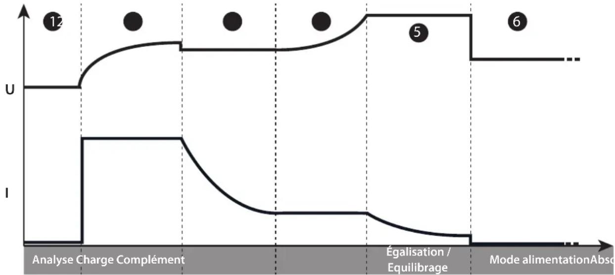
The SHOWROOM mode (outside of the «no battery» function) incorporates an automatic charging algorithm adapted to all types of batteries (lead and lithium), in order to guarantee an optimal charge level for demonstration vehicles. This function is perfectly compatible with the presence of consumers on the battery.
line
| Phase | U (voltage) | I (current) | | ------------------------- | ----------- | ----------- | | 12 | High | Low | | 5 | Medium | Low | | 6 | Low | Low |Step 1: Analysis
Analysis of the battery condition (charge level, inversion, etc.) polarity, wrong battery connected, etc).
Step 2: Charging
Fast charging at maximum current until U1 is reached (ex: 13.8 V to 12V)
Step 3: Absorption
Charge under constant voltage U1 (ex: 13.8 V in 12V) Maximum duration 1 hour.
Step 4: Complement
Gradual increase of the voltage up to U2
(ex: 14.4 V to 12V Maximum duration 2 hours.
Step 5: Equalization / Balancing
Maintaining the voltage U2 (ex: 14.4V at 12V) Maximum duration 2 hours.
Step 6: Power supply mode
Application of the selected voltage.
• Abnormal undervoltage protection:
This protection prevents the risk linked to possible short circuits or battery being too damaged. The charger will automatically stop if the voltage is abnormally low for more than 10 minutes.
TESTER MODE
General navigation :
1 Use the arrows to select the test to be performed
2 Press the START/STOP button to start the test



Test
Voltage Test
Engine start Test
Alternator Test
- Voltage test:
This mode allows you to view the voltage at the terminals of the charging clamps and thus use your GYSFLASH as a voltmeter, in order to measure the battery voltage.
Voltage Test
12.5v
- Start-up test:
The purpose of this mode is to evaluate the state of a vehicle starting system (starter + battery) when the engine is turned on. This test must be done with the battery connected to the vehicle.
| 1 Use the arrows to select the nominal voltage of the vehicle battery | |
| 2 Press the SELECT button to confirm | |
| 3 Connect the clamps to the vehicle battery | 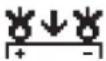 |
| 4 Start the engine by turning the ignition key |  |
5 The charger automatically detects the engine start attempt and runs a calculation algorithm to determine the state of the start system.
Test
Voltage Test
Engine start Test
Alternator Test
Engine start Test
Umin=12.5v

Test result: The charger indicates the minimum value of the battery voltage perceived during the engine start phase, as well as the status of the start system in the form of a gauge.
- Alternator test :
This mode is used to determine the condition of the alternator in the vehicle. This test is performed on a vehicle with the engine running.
1 Use the arrows to select the nominal voltage of the vehicle battery
2 Press the SELECT button to confirm


Test
Voltage Test
Engine start Test
Alternator Test
Test result: The charger indicates the voltage provided by the vehicle alternator, as well the alternator status in the form of a gauge.
Alternator Test
13.5v

PROTECTIONS
This device is protected against short circuits and polarity reversals. It has an anti-spark system that prevents sparks when connecting the charger to the battery. The device will not deliver current if there is no battery detected (no voltage in the clamps). This charger is protected against handling errors by an internal fuse.
CONFIGURATION MENU
The configuration menu can be accessed by pressing the button

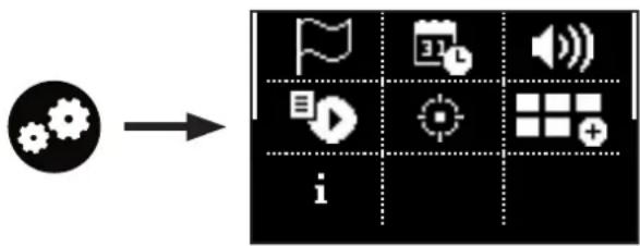
flowchart
graph LR
    A["Input Gear Icon"] --> B["Display Icon"]
    B --> C["Video Icon"]
    B --> D["Audio Icon"]
    B --> E["Grid Icon"]
    B --> F["Search Icon"]
    B --> G["Display Plus Icon"]
Language selection
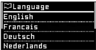
text_image
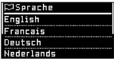
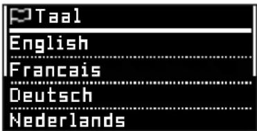
Language English Francais Deutsch NederlandsSelection of the onscreen language, 19 different options are available.
Date / Time
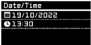
text_image
Date/Time 19/10/2022 13:30Option to set the date and time on the device.
Sound

The audio of the Gysflash and the external light module can be activated or deactivated.
Traceability
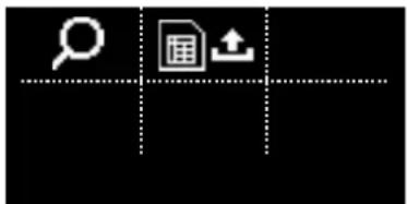
text_image
Icon set with magnifying glass and document symbol, including a upload icon, on black backgroundYou can view or retrieve the last 1,000 historical charging records.

Explore Data Possibility of displaying the data collected over the last 1,000 loads on screen.
Export data (.csv)
The data collected from the last 1,000 charges can be exported to a USB stick in .CSV format.
| 1 Connect the USB stick to the Gysflash | |
| 2 Enter the «Export DATA» submenu. | |
| 3 Confirm that the charging data has been saved. | |
| 4 | The Gysflash will then copy the charging data to the USB stick in the form of «.CSV» file. |
Cable calibration
Cable calibration
Automatic
Manual
Cables can be calibrated either automatically (recommended) or manually.
This procedure is used to calibrate the charging cables of the unit, so the Gysflash can effectively compensate for any voltage drop caused by the cables. We strongly recommend that you carry out this procedure every time you replace your cables, or if they are getting worn.
Automatic calibration (recommended)
Cable calibration



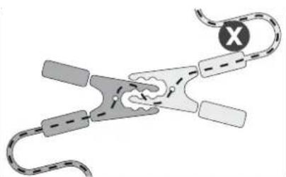
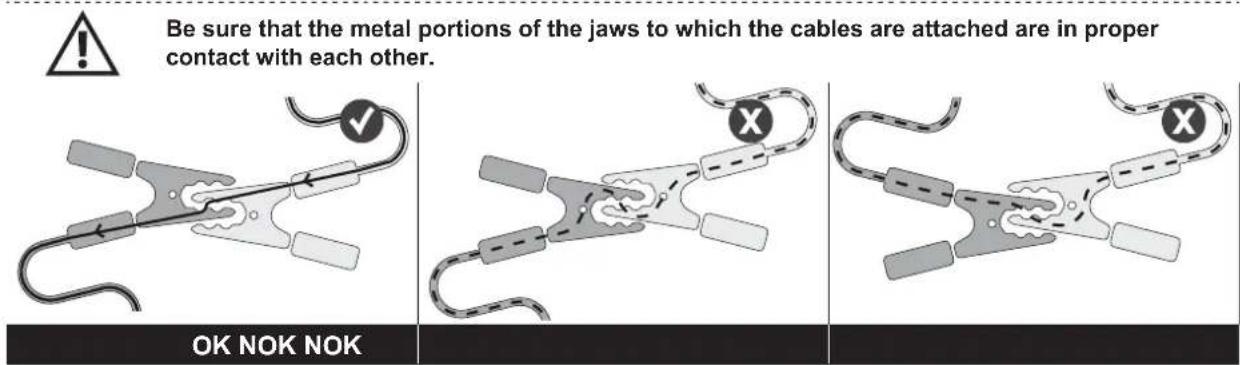
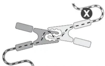
To calibrate, simply short-circuit the charging clamps and then confirm. The device then automatically calculates the cable resistance.
text_image
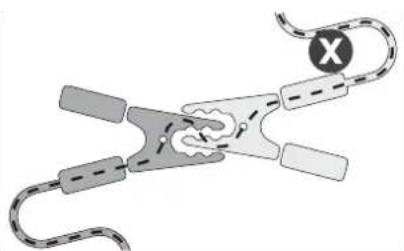
Be sure that the metal portions of the jaws to which the cables are attached are in proper contact with each other. OK NOK NOKManual calibration (not recommended)
Cable calibration
11.5mΩ
The cable resistance can be set manually.
Warning: this value must include the internal resistance of the Gysflash.
Advanced settings
This menu gives you access to the advanced features of your Gysflash.
+ Option
+Options
□Auto-Detect □Auto-Restart

Activated Deactivated
This menu is used to select whether or not to activate the Auto-Detect and Auto-Restart functions.
Auto-detect function: With this function, the Gysflash automatically initiates a charge when contact is detected on tAhe output. If this option («Auto-detect») is disabled, a contact on the output will only be detected using the «Auto-select» mode, and all other modes can only be initiated by a manual START.
Auto-restart option: This function allows the Gysflash to restart automatically in the event of a power cut.
Portability
text_image
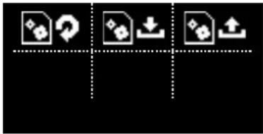
Icon set with document, download, and upload symbols in a grid layoutThis menu is used to import, export, or initialize configurations for the gysflash. Your GYSFLASH is equipped with USB connectivity that extends its functionality by creating custom configurations on your computer that can then be downloaded to the device via a simple USB stick. The custom configuration allows you to add, delete or modify charging modes and profiles, so that your charger can be adapted to your needs.

Restore CONFIG
This operation restores the original (factory) configuration of the Gysflash following any manual changes to modes or parameters.
| 1 Enter «Restore CONFIG» submenu. |
| 2 Confirm the restoration of the configuration. |
| 3 The Gysflash will then be restored to its original (factory) configuration. |
Import CONFIG (.gfc)
This action downloads a complete new factory configuration to the Gysflash. The current configuration is then overwritten.
| 1 | First, make sure that the».gfc» file corresponding to the new configuration is present on the USB stick. This file must not be located in a folder or subfolder of the USB stick. |
| 2 Plug the USB stick into the Gysflash. | |
| 3 Enter the «Import CONFIG» submenu. | |
| 4 Select the relevant file to install. | |
| 5 Confirm file installation. | |
| 6 The Gysflash will then install the new configuration. | |

Export CONFIG (.gfc)
This action downloads the current Gysflash configuration to a USB stick.
| 1 Plug the USB stick into the Gysflash. |
| 2 Enter the «Export CONFIG» submenu. |
| 3 Confirm that the configuration has been saved. |
| 4 The Gysflash will then save the current configuration to the USB stick. |
Custom configuration
List of modes and profiles available for customization:
| CHARGE MODE | |||
| Charge type: | Charge profiles | Charging vol-tage | |
| Pb-CHARGE | normal | 2.40 V/cell Charging | profile for lead batteries of the types Gel, MF, EFB, SLA... |
| AGM | 2.45 V/cell | Charging profile for most AGM lead-acid batteries including START and STOP.However, some AGM batteries require a lower voltage charge (Normal profile). Check the battery manual if in doubt. | |
| water | 2.45 V/cell Charging | profile for open liquid-type lead-acid batteries with plug. | |
| Easy | 2.40 V/cell | Charging profile dedicated to lead batteries that automatically adapts the charging current according to the size of the battery.However, for maximum charge optimization, it is recommended, when possible, to use normal, AGM or liquid charge curves. | |
| boost | 2.42 V/cell | Maximum current charge for lead-acid battery. This type of charge is ultra-fast.Warning : this type of charge must remain occasional in order to preserve battery life. | |
| recovery+ | 2.40 - 2.50 V/cell | Charging profile for the recovery of severely damaged lead batteries. It is essential to recover the battery outside the vehicle to avoid damaging the vehicle electronics and in a well ventilated area.Caution: Recovery voltage up to 4.0 V/cell. | |
| Ca/Ca recov | 2.45 - 2.66 V/cell | Charging profile for calcium battery recovery. The battery must be recovered outside the vehicle to avoid damaging the vehicle's electronics and in a well-ventilated area.Caution: Recovery voltage can reach up to 2.75 V/cell. | |
| Li-CHARGE | LFP/LiFe-PO4 | 3.60 V/cell Charging | profile for Lithium batteries type LFP (Lithium Ferro Phosphate) |
| Li-ion std | 4.20 V/cell | Charging profile for standard lithium-ion batteries based on Manganese or Cobalt (NMC, LCO, LMO, MCO...) | |
| LFP cell+ | 3.60 V/cell | Charging profile dedicated to LFP (Lithium Ferro Phosphate) type lithium-ion cells with selection of the number of cells in series to be charged. | |
| Li-ion cell+ | 4.20 V/cell | Charging profile dedicated to standard lithium-ion cells based on Manganese or Cobalt (NMC, LCO, LMO, MCO...) with selection of the number of cells in series to be charged. | |
| TRACTION | water | 2.42 V/cell Charging | profile dedicated to open lead traction batteries for forklift trucks. |
| gel | 2.35 V/cell Charging | profile dedicated to gel-type traction batteries for forklift trucks. | |
| POWER MODES | |
| Showroom | Maintains the battery's state of charge and supplies power when using the electrical consumers of a demonstration vehicle. |
| DIAG+ | Supplies energy requirements during the vehicle diagnostic work. |
| CHANGE BAT. | Allows to keep the vehicle power supply during battery replacement, in order to preserve the memory of the vehicle's ECUs.Caution: Reverse polarity during use can be harmful to the charger and vehicle electronics. |
| STARTER MODE | Starting aid for combustion vehicles. Allows the battery to be precharged and the charger to send the maximum current during the engine starting phase (the charger stops automatically after 30 minutes). |
| POWER SUPPLY | Allows the charger to be used as an adjustable stabilized power supply with high power. The voltage to be regulated and the current limitation are fully adjustable.Caution: Reverse polarity during use can be harmful to the charger and vehicle electronics. |
| Li-SUPPLY/LFP | Mode intended to supply lithium-ion cells of the LFP type (Lithium Ferro Phosphate) with selection of the number of cells in series, adjustment of the voltage and current to be applied. |
| Li-SUPPLY/Li-ion | Mode intended to supply standard lithium-ion batteries based on Manganese or Cobalt (NMC, LCO, LMO, MCO...) with selection of the number of cells in series, adjustment of the voltage and current to be applied. |
GYS offers you predefined configurations adapted to each application.
These settings are available on the product page of the GYS website:
Gysflash V01.00 ▼

| Configuration file (gys.fr) | Applications | CHARGE MODE POWER MODES | MISCELLANEOUS | |||||||||||||||||||
| Pb-CHARGE Li-CHARGE | TRACTION | SHOWROOM | DIAG+ | CHANGE BAT. | STARTER MODE | POWER SUPPLY | Li-SUPPLY/LFP | Li-SUPPLY/Li-ion | TESTER MODE | |||||||||||||
| normal | AGM | water | Easy | Boost | Recovery+ | Ca / Ca recov | LFP/LiFePO4 | Li-ion std | LFP cell+ | Li-ion cell+ | water | gel | ||||||||||
| 1_gys_original.gfc Initia | configuration of the charger | √ | √ | √ | √ | √ | √ | √ | √ | |||||||||||||
| 2_car_extended.gfc Extensive features for garages | √ | √ | √ | √ | √ | √ | √ | √ | √ | √ | √ | √ | √ | √ | √ | √ | ||||||
| 3_showroom_only.gfc | Simplified version for dealerships and demonstration vehicles | √ | ||||||||||||||||||||
| 4_pro_lithium.gfc Professional of lithium battery | √ | √ | √ | √ | √ | √ | √ | |||||||||||||||
| 5 traction.gfc Forklift truck, electric pallet truck, stacker... | √ | √ | ||||||||||||||||||||
| 6_full_version.gfc Full version | √ | √ | √ | √ | √ | √ | √ | √ | √ | √ | √ | √ | √ | √ | √ | √ | √ | √ | √ | √ | √ | √ |
√ Only on 24 V and 48 V models.
^* DIAG+ (Pro) - 16 V selection possible.

Multi-chargers
text_image
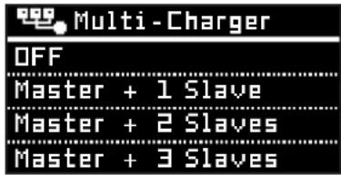
Multi-Charger OFF Master + 1 Slave Master + 2 Slaves Master + 3 SlavesThis menu is used to configure the Multi-charger mode (see page 36 for details). Select «OFF» for normal use with a single Gysflash.
i
Information
text_image
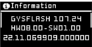
Information GYSFLASH 107.24 HW08.00-SW01.00 22.11.069909.000000This menu displays information about your Gysflash:
- Device name
- Hardware/software versions
- Serial number
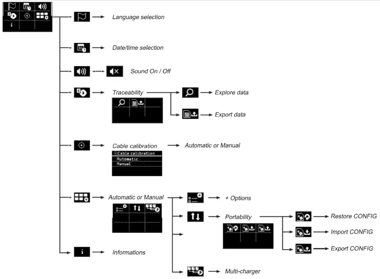
CONFIGURATION MENU STRUCTURE
flowchart
graph TD
    A["User Interface"] --> B["Language selection"]
    A --> C["Date/time selection"]
    A --> D["Sound On / Off"]
    A --> E["Traceability"]
    E --> F["Explore data"]
    E --> G["Export data"]
    A --> H["Cable calibration"]
    H --> I["Automatic or Manual"]
    A --> J["Automatic or Manual"]
    J --> K["+ Options"]
    J --> L["Portability"]
    L --> M["Restore CONFIG"]
    L --> N["Import CONFIG"]
    L --> O["Export CONFIG"]
    A --> P["Informations"]
    P --> Q["Multi-charger"]
CONNECTIVITY MODULES
Your GYSFLASH is equipped with a DB9 type socket allowing you to connect various additional modules offered by GYS such as a printer, Ethernet or other module in order to further extend the possibilities of your charger.
LIST OF ERROR CODES
| Error code Meaning Solutions | ||
| Err01: Int_1 - Err02: Int_2Err23: Int_3 - Err24: Int_4 | Electronic problemDefective charger | Contact the reseller |
| Err03: Fuse_NOK Output fuse out of order Have the fuse replaced by a qualified person | ||
| Err04: T>Tmax Abnormal overheating Contact the reseller | ||
| Err05: (+)(-) | The polarity has been reversed on the clamps | Connect the red clamp to the (+) and the black clamp to the (-) of the battery. |
| Err06: U>_V | Overvoltage detected at the clamp terminals | Disconnect the clamps |
| Err07: No_bat | Battery not connected | Check that the battery is correctly connected to the charger |
| Err08: U<__V Abnormally low battery voltage | Check that the selected mode is compatible with the battery voltage (e. g. : 6 V battery in 24 V mode) | |
| Charge the battery via CHARGE mode | ||
| Battery to be replaced | ||
| Err09: U>_V Abnormally high battery voltage | Check that the selected mode is compatible with the battery voltage (e. g. : 24 V battery in 12 V mode) | |
| Err10: U<2.0V | Short-circuit detected during the charge process | Check the assembly |
| Err11: Time_Out | Triggering the time limit Presence of a consumer on the battery disrupting the charge | |
| Abnormally long charge Battery to be replaced | ||
| Err12: Q>___Ah Tripping the overcharge protection | Presence of a consumer on the battery disrupting the charge | |
| Battery to be replaced | ||
| Err13: U<__V | Abnormally low battery voltage when checking the charge | Battery to be replaced |
| Err14: Bat_UVP | Abnormally low battery voltage during UVP Wake up | Presence of a short circuit, check the assembly |
| Battery to be replaced | ||
| Err15: U<__V Battery too low | Check that the selected mode is compatible with the battery voltage (e. g. : 24 V battery in 12 V mode) | |
| Battery to be replaced | ||
| Err16: Bat_NOK Battery out of order Battery to be replaced | ||
| Err17: Recov_NOK Battery recovery failure Battery to be replaced | ||
| Err18: U>0V | Presence of a voltage at the clamp terminals when calibrating the cables | Check the assembly |
| Err19: Cable_NOK Cable calibration failure | Charging cables to be replaced | |
| Incorrect connection, check the assembly | ||
| Err20: U<__V | Triggering of the abnormal undervoltage protection | Presence of a short circuit, check the assembly |
| Err21: U<__V or Err22: U<__V | Abnormally low battery voltage during charging | Battery to be replaced |
| Presence of a consumer on the battery | ||
 | Key not detected Check that the USB key is correctly connected to the charger. | |
 | No configuration file (.gfc) is present on the key | Check that your files are present at the root of the USB key. Do not put them in a folder or sub-folder. |
| [2478] | Corrupted file | The file you wish to download is corrupted. Delete and reinstall the file on the key. |
| Err27: Cable_NOK | Multi-charger mode :Parallel charging cables fail | Load cables to be replaced. |
| Poor connection, check assembly (PHM). | ||
| To switch back to single charger operation, select OFF for the Multi-Charger function. | ||
| Err28: COM_NOK | Multi-charger mode :Communication failure between chargers | No communication, check SHM mounting and SLAVE X charger configuration. |
| To switch back to single charger operation, select OFF for the Multi-Charger function. | ||
WARRANTY
The warranty covers faulty workmanship for 2 years from the date of purchase (parts and labour).
The warranty does not cover:
- Transit damage.
- Normal wear of parts (eg. : cables, clamps, etc..).
- Damages due to misuse (power supply error, dropping of equipment, disassembling).
- Environment related failures (pollution, rust, dust).
In case of failure, return the unit to your distributor together with:
- The proof of purchase (receipt etc ...)
- A description of the fault reported
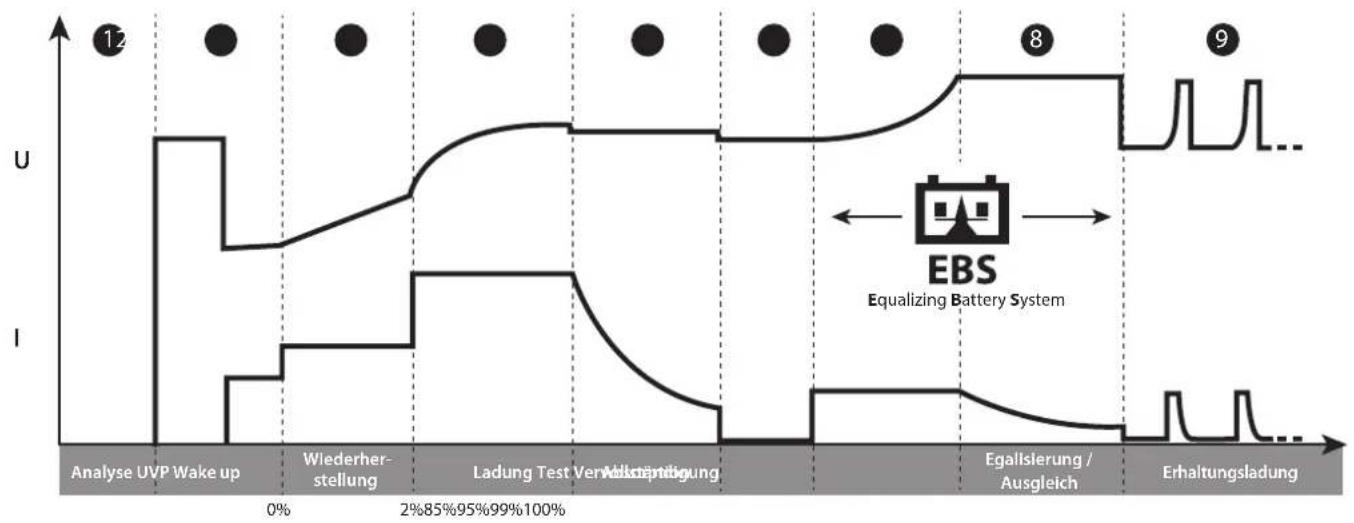
Lithium-Ladekurve (LFP):
line
| Event | U | I | | --- | --- | --- | | Analyse UVP Wake up | High | Low | | Wiederherstellung | Low | Low | | Ladung Test Veränderung | Medium | Low | | Veränderung | High | Low | | Erhaltungsladung | Low | Low | | Equalization (8) | High | Low | | Equalization (9) | High | Low |1. Stufe: Analyse
line
| Point | U | I | |-------|------|------| | 12 | High | Low | | 5 | High | Low | | 6 | Low | Low |1. Stufe: Analyse
flowchart
graph LR
    A["Input Gear Icon"] --> B["Processing Panel"]
    B --> C["Output: Flag, Video, Audio, Target, Grid +"]

Auswahl der Sprache
text_image
Sprache English Francais Deutsch Nederlandstext_image
Icon set with magnifying glass, document, and upload symbol on black backgroundnatural_image
Diagram of a hair clip with attached clips and a circular connector (no text or symbols)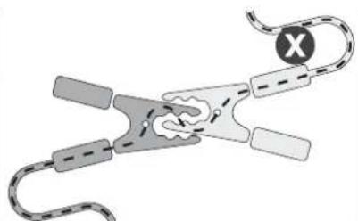
natural_image
Diagram of a biological or mechanical structure with curved and straight elements, no visible text or symbols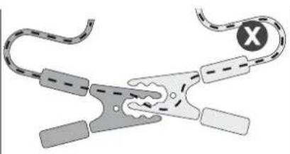
natural_image
Illustration of a mechanical clamp or tool with curved and straight ends, no text or symbols presentOK NOK NOK
text_image
Icon set with document, upload, download, and connection symbols arranged in a gridline
| Point | U (voltage) | I (current) | |-------|-------------|-------------| | 1 | High | Low | | 2 | Medium | Low | | 3 | High | Low | | 4 | High | Low | | 5 | High | Low | | 6 | Low | Low |Etapa 1 : Análisis
natural_image
Pure icon grid with magnifying glass, document, and upload symbol (no text or labels)natural_image
Diagram of a mechanical clamp or spring with curved wires and a circular button (no text or symbols)OK NOK NOK
natural_image
Diagram of a mechanical or electrical component with curved and straight sections, no visible text or symbols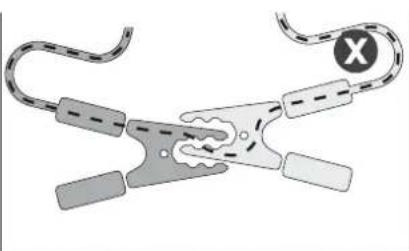
natural_image
Illustration of a wire clamp tool with curved leads and a circular symbol (no text or labels)text_image
Icon set grid with document, download, and upload icons in a rowtext_image
Auto -Detect 12.5v Zaryadkaline
| Stage | U | I | | ----------------- | ---- | ---- | | Analyse | 0% | 0% | | Récupération | 0% | 0% | | Test | 10% | 0% | | Désulfatation | 10% | 0% | | Charge | 20% | 0% | | Absorption | 80% | 0% | | Refresh (if option activated) | 95% | 0% | | Maintien de charge | 100% | 0% |Этап 1 : Анализ
line
| Stage | U | I | |-------|----|----| | Analyse Charge Complément | 0 | 0 | | Égalisation / Equilibrage | 0 | 0 | | Mode alimentation Absorption | 0 | 0 |Этап 1: Анализ
text_image
Icon set with magnifying glass, document, and upload symbol on black backgroundnatural_image
Diagram of a coiled cable or clamp device with no visible text or symbolsOK NOK NOK
natural_image
Diagram of a biological or mechanical structure with curved and straight elements, no visible text or symbols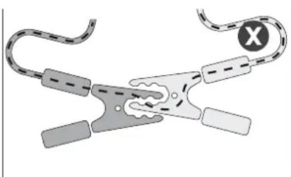
natural_image
Illustration of a mechanical clamp or tool with curved and straight ends, no text or symbols presenttext_image
Icon set for document operations: download, upload, and upload icon with corresponding iconstext_image
Multi-zaryad OFF Master + 1 Slave Master + 2 Slaves Master + 3 Slavestext_image
Diagram illustrating various electrical safety symbols and correct circuit conditions, including battery, gloves, test tube, and circuit breakers.line
| Stage | U | I | | ----------------- | ---- | ---- | | Analyse | 0 | 0 | | Récupération | 12 | 0 | | Test | 12 | 0 | | Désulfation | 12 | 0 | | Charge | 12 | 0 | | Absorption | 12 | 0 | | Refresh (all option active) | 12 | 0 | | Maintien de charge | 12 | 0 |Stap 1 : Analyse
line
| Stage | U | I | |-------|----|----| | Analyse Charge Complément | 0 | 0 | | Égalisation / Equilibrage | 0 | 0 | | Mode alimentation Absorption | 0 | 0 |Stap 1 : Analyse
flowchart
graph LR
    A["Gear icon"] --> B["Processing Grid"]
    style A fill:#fff,stroke:#000
    style B fill:#999,stroke:#000

Keuze taal
text_image
Taal English Francais Deutsch Nederlandstext_image
Icon set with magnifying glass and document symbol, likely representing search or data analysis functionstext_image
Diagram illustrating three stages of a mechanical or electrical device operation with labeled components and directional arrows.OK NOK NOK
text_image
Multi-lader OFF Master + 1 Slave Master + 2 Slaves Master + 3 Slavesline
| Stage | U | I | | ----------------- | ---- | ---- | | Analyse | 0% | 0% | | Récupération | 0% | 0% | | Test | 10% | 0% | | Désulfation | 10% | 0% | | Charge | 20% | 0% | | Absorption | 20% | 0% | | Refresh (all option active) | 95% | 0% | | Maintien de charge | 100% | 0% |Fase 1 : Analisi
line
| Phase | U (voltage) | I (current) | | ------------------------- | ----------- | ----------- | | 12 | High | Low | | 5 | Medium | Low | | 6 | Low | Low |Fase 1 : Analisi
text_image
Icon set with magnifying glass and document symbol, including a upload icon, on black backgroundtext_image
OK NON OK NON OKtext_image
Icon set grid with document, upload, download, and upload icons above a dotted linetext_image
Multi-carica OFF Master + 1 Slave Master + 2 Slaves Master + 3 Slavestext_image
Diagram of a vehicle chassis with labeled components and connection points, including sensors, connectors, and control buttons.1
FR : Connecteur de charge
EN : Charging connector
DE : Ladeanschluss
ES : Conector de carga
RU:Коннектор зарядки
NL : Aansluiting laden
IT: Connettore di carica
2
FR : Interrupteur marche/arrêt
EN : On/off switch
DE : EIN/AUS Schalter
ES : Interruptor encendido / apagado
RU: Переключатель ВКЛ/ВЫКЛ
NL : Schakelaar aan/uit
IT : Interruttore avvio/stop
3
natural_image
Technical line drawing of a mechanical device with internal components and mounting holes (no text or labels)2
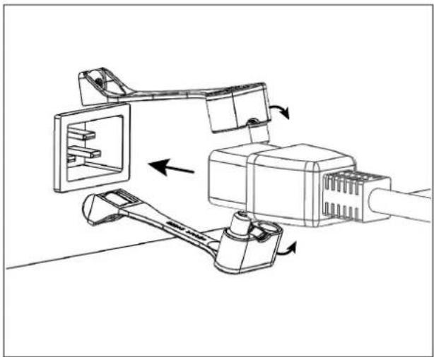
natural_image
Technical line drawing of a mechanical assembly with no visible text or symbols3
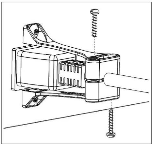
natural_image
Technical line drawing of a mechanical assembly with screws and a shaft (no text or symbols)GYS France
Siège social / Headquarter