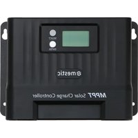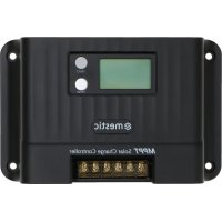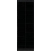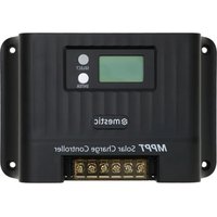
MSC-4020 - Controller Mestic - Free user manual and instructions
Find the device manual for free MSC-4020 Mestic in PDF.


| Product type | MPPT solar charge controller |
| Brand | Mestic |
| Model | MSC-4020 |
| System voltage | 12V / 24V (auto-detection) |
| Rated charge current | 20 A |
| Maximum solar panel power | 250 W (12V) / 520 W (24V) |
| Maximum PV open circuit voltage | 100 V (protection at 95 V, recovery at 90 V) |
| MPPT voltage range | (battery voltage + 2 V) to 72 V |
| MPPT tracking efficiency | > 99 % |
| Charge conversion efficiency | 85 % - 98 % |
| Supported battery types | Sealed lead-acid (SLD), gel (GEL), flooded (FLD), lithium (LI), custom (USE, USE LI) |
| Communication | TTL (9600 bps), RS485 (RJ45, adjustable baud rate), Bluetooth and CAN optional |
| Display | LCD with parameter display and alarm codes |
| Dimensions (L x W x H) | 181 x 118 x 61.7 mm |
| Weight | 650 g |
| Protection level | IP32 |
| Self-consumption | ≤ 10 mA |
| Cooling mode | Natural dissipation via aluminum fins |
| Ambient temperature range | -35 °C to 66 °C |
| Maintenance | Check radiator cleanliness, tighten connections, replace damaged cables |
| Safety | Protection against PV overvoltage, polarity reversal, short circuit, overload, overheating, etc. |
| Grounding | Common negative |
Frequently Asked Questions - MSC-4020 Mestic
User questions about MSC-4020 Mestic
0 question about this device. Answer the ones you know or ask your own.
Ask a new question about this device
Download the instructions for your Controller in PDF format for free! Find your manual MSC-4020 - Mestic and take your electronic device back in hand. On this page are published all the documents necessary for the use of your device. MSC-4020 by Mestic.
USER MANUAL MSC-4020 Mestic
natural_image
Technical line drawing of a mechanical component with no visible text or symbols
line
| I (A) | VP curve (A) | VI curve (A) | P(W) | |-------|--------------|--------------|------| | 0.0 | 0.0 | 5.0 | 94.5 | | 1.0 | 1.0 | 4.5 | 87.5 | | 2.0 | 2.0 | 4.0 | 73.5 | | 3.0 | 3.0 | 3.5 | 67.5 | | 4.0 | 4.0 | 3.0 | 61.0 | | 5.0 | 4.5 | 2.5 | 54.5 | | 6.0 | 4.5 | 2.0 | 49.0 | | 7.0 | 4.5 | 1.5 | 43.5 | | 8.0 | 4.5 | 1.0 | 38.0 | | 9.0 | 4.5 | 0.5 | 32.5 | | 10.0 | 4.5 | 0.0 | 27.0 | | 11.0 | 4.5 | 0.0 | 21.5 | | 12.0 | 4.5 | 0.0 | 16.0 | | 13.0 | 4.5 | 0.0 | 10.5 | | 14.0 | 4.5 | 0.0 | 5.0 | | 15.0 | 4.5 | 0.0 | 0.0 | | 16.0 | 4.5 | 0.0 | 0.0 | | 17.0 | 4.5 | 0.0 | 0.0 | | 18.0 | 4.5 | 0.0 | 0.0 | | 19.0 | 4.5 | 0.0 | 0.0 | | 20.0 | 4.5 | 0.0 | 0.0 | | 21.0 | 4.5 | 0.0 | 0.0 | | 22.0 | 4.5 | 0.0 | 0.0 | | 23.0 | 4.5 | 0.0 | 0.0 | | 24.0 | 4.5 | 0.0 | 0.0 | | 25.0 | 4.5 | 0.0 | 0.0 | | 26.0 | 4.5 | 0.0 | 0.0 | | 27.0 | 4.5 | 0.0 | 0.0 | | 28.0 | 4.5 | 0.0 | 0.0 | | 29.0 | 4.5 | 0.0 | 0.0 | | 30.0 | 4.5 | 0.0 | 0.0 | | 31.0 | 4.5 | 0.0 | 0.0 | | 32.0 | 4.5 | 0.0 | 0.0 | | 33.0 | 4.5 | 0.0 | 0.0 | | 34.0 | 4.5 | 0.0 | 0.0 | | 35.0 | 4.5 | 0.0 | 0.0 | | 36.0 | 4.5 | 0.0 | 0.0 | | 37.0 | 4.5 | 0.0 | 0.0 | | 38.0 | 4.5 | 0.0 | 0.0 | | 39.0 | 4.5 | 0.0 | 0.0 | | 40.0 | 4.5 | 0.0 | 0.0 | | Note: The data is extracted from the image in the code and displayed as a PNG image named 'Fig .2-1 Uitgangskarakteristik occupaneel'. The text labels are 'I (A)' and 'P (W)'. The chart includes a legend for the curves: 'VP curve' and 'VI curve'. The 'PWM charging' label is marked on the left side of the chart.line
| Time | MPPT (Charging voltage) | Constant voltage charging (Charging voltage) | Floating charging (Charging voltage) | |---|---|---|---| | 0 | 0 | 0 | 0 | | 1 | High | Low | Low | | 2 | High | Low | Low | | 3 | High | Low | Low | | 4 | High | Low | Low | | 5 | High | Low | Low | | 6 | High | Low | Low | | 7 | High | Low | Low | | 8 | High | Low | Low | | 9 | High | Low | Low | | 10 | High | Low | Low | | 11 | High | Low | Low | | 12 | High | Low | Low | | 13 | High | Low | Low | | 14 | High | Low | Low | | 15 | High | Low | Low | | 16 | High | Low | Low | | 17 | High | Low | Low | | 18 | High | Low | Low | | 19 | High | Low | Low | | 20 | High | Low | Low | | 21 | High | Low | Low | | 22 | High | Low | Low | | 23 | High | Low | Low | | 24 | High | Low | Low | | 25 | High | Low | Low | | 26 | High | Low | Low | | 27 | High | Low | Low | | 28 | High | Low | Low | | 29 | High | Low | Low | | 30 | High | Low | Low | | 31 | High | Low | Low | | 32 | High | Low | Low | | 33 | High | Low | Low | | 34 | High | Low | Low | | 35 | High | Low | Low | | 36 | High | Low | Low | | 37 | High | Low | Low | | 38 | High | Low | Low | | 39 | High | Low | Low | | 40 | High | Low | Low | | 41 | High | Low | Low | | 42 | High | Low | Low | | 43 | High | Low | Low | | 44 | High | Low | Low | | 45 | High | Low | Low | | 46 | High | Low | Low | | 47 | High | Low | Low | | 48 | High | Low | Low | | 49 | High | Low | Low | | 50 | High | Low | Low | | 51 | High | Low | Low | | 52 | High | Low | Low | | 53 | High | Low | Low | | 54 | High | Low | Low | | 55 | High | Low | Low | | 56 | High | Low | Low | | 57 | High | Low | Low | | 58 | High | Low | Low | | 59 | High | Low | Low | | 60 | High | Low | Low | | 61 | High | Low | Low | | 62 | High | Low | Low | | 63 | High | Low | Low | | 64 | High | Low | Low | | 65 | High | Low | Low | | 66 | High | Low | Low | | 67 | High | Low | Low | | 68 | High | Low | Low | | 69 | High | Low | Low | | 70 | High | Low | Low | | 71-72: Charging current Time axis from left to right Charging voltage: MPPT Constant voltage: MPPT Floating charging: MPPT Charging voltage: Floating charging: Floating charging Charging current: Charging currentline
| Time Point | Charging Voltage (MPPT) | Charging Current (Current) | | ---------- | ------------------------ | -------------------------- | | Start | 0 | 0 | | Peak | Constant | - | | End | Constant | - |flowchart
graph TD
    A["Main menu (voltage)"] --> B["14.40 V"]
    C["Main menu (current)"] --> D["20.00 V"]
    B --> E["Battery voltage"]
    D --> F["Battery voltage"]
    E --> G["12.00 V"]
    F --> H["12.00 V"]
    G --> I["Charging current"]
    H --> J["Charging current"]
    I --> K["PV voltage"]
    J --> L["PV current"]
    K --> M["17.00 V"]
    L --> N["17.00 V"]
    M --> O["Load mode"]
    N --> P["Load mode"]
    O --> Q["Operating day"]
    P --> R["Operating day"]
    Q --> S["Device temperature"]
    R --> T["Device temperature"]
    S --> U["Operating day"]
    T --> V["Operating day"]
    U --> W["Operating day"]
    V --> X["Operating day"]
    W --> Y["Operating day"]
    X --> Z["Operating day"]
    Y --> AA["Operating day"]
    Z --> AB["Operating day"]
    AA --> AC["Operating day"]
    AB --> AD["Operating day"]
    AC --> AE["Operating day"]
    AD --> AF["Operating day"]
    AE --> AG["Operating day"]
    AF --> AH["Operating day"]
    AG --> AI["Load Current"]
    AH --> AJ["Load Current"]
    AI --> AK["Load Current"]
    AJ --> AL["Load Current"]
    AK --> AM["Load Current"]
    AL --> AN["Load Current"]
text_image
Equalizing charging 146 v Boost charging 144 v Floating charging 138 v Over-discharge voltage 111 v Over-discharge reconnect voltage 126 v Changing reconnect voltage 132 v8.5 Systeem spanning
flowchart
graph LR
    A["ON on sc"] --> B["OF on sc"]
8.13 Over-ontlading vertraging
text_image
@mestic MPPT Solar Charge Controller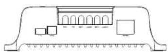
Model: MSC-4010
Productafmeting: 155*99*41.7mm
Montage gatafstand: 137°77mm Vaste gatenpositie: φ4.5mm
18.2 MSC-4020
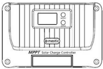
text_image
BLACK EMISTIC @emestic MPPT Solar Charge Controller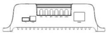
Model: MSC-4020
Producta/meting: 181*118*61.7mm
Montage gatafstand: 161*96mm Vaste gal positie: φ4.5mm
20 21
NL
18.3 MSC-4030

text_image
@mestic MPPT Solar Charge Controller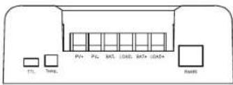
text_image
PV+ PL RDT LOKE RDT+LOKE+ RoHSModel: MSC-4030
Productafmeting: 187*133*72mm
Montage gatafstand: 174*100mm
Vaste gatenpositie: φ5mm
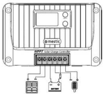
18. System wiring diagram
18.1 System wiring diagram
text_image
@mestic MPPT Solar Charge Controllermestic
NL
Solar charge controller MPPT MSC-4010/-4020/-4030
natural_image
Technical line drawing of a mechanical component with no visible text or symbolsRelax... it's mestic
User instructions EN
Thank you for choosing our products!
Safety Instructions
- Since the applicable voltage of the controller exceeds the safety limit of human body, please read the manual carefully before operation and operate this controller after the safety operation training is completed.
- Since no part is required to be maintained or repaired inside the controller, please do not disassemble and repair the controller by yourself.
- Please install the controller indoors to avoid exposure of components and keep water away from the controller.
- Since the cooling fin will be very hot during operation, please install the controller in a well-ventilated place.
- Suitable fuse or circuit breaker is recommended to be equipped outside the controller.
- Before installing and adjusting the wiring of the controller, make sure to disconnect the wiring of the photovoltaic array and the fuse or circuit breaker near the accumulator battery terminals.
- After installation, check whether all wiring is tightly connected to avoid the danger of heat accumulation due to loose connection.
Warning: Indicates that this operation is dangerous and safety preparations must be made before operation.
Attention: Indicates destructive operation.
Tips: Indicates suggestions and tips to the operator.
EN
1. Product introduction
1.1 Product overview
The Shiner series controller adopts the industry-leading MPPT to achieve the maximum energy tracking for the solar panel, that is, it can quickly and accurately track the maximum power point of the solar battery on any condition, and obtain the maximum energy of the solar panel in real time, significantly improving the energy utilization rate of the solar system. It is widely used as the core control component in the off-grid PV systems to manage the work of solar panels, batteries, and loads. Besides, it has complete software and hardware fault detection and protection functions to avoid damage to product components caused by installation errors and system faults to the greatest extent.
1.2 Product feature
◆ Adopt MPPT with tracking efficiency up to 99.9%.
◆ Support full-power charging and discharging at one time.
◆ Support multiple battery types such as sealed battery, gel battery, flooded battery, lithium battery and user-defined battery.
◆ Support lithium battery and lead-acid activated battery.
◆ Support the charging current setting.
◆ Support full-charging setting.
◆ Support temperature compensation.
◆ Support 17 load operating modes.
◆ Support capacitive loads and inductive loads.
◆ Save historical data for 200 consecutive days.
◆ Support RS485 communication of standard Modbus protocol with adjustable baud rate.
◆ Support TTL communication of standard Modbus protocol with fixed baud rate.
◆ Support Bluetooth communication (optional).
◆ Support CAN communication (optional).
◆ Possess complete charging and discharging protection mechanisms for overvoltage, overcurrent, overload, over-temperature, short circuit, etc.
- Adopt high-quality aluminum radiator and high-temperature derating treatment to ensure reliable and efficient operation in various operating conditions.
EN
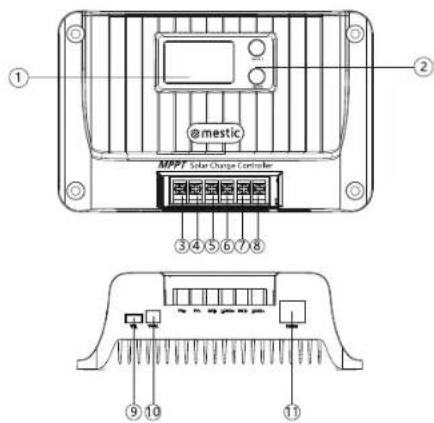
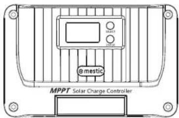
1.3 Appearance and interface description
text_image
① @mestic MPPT Solar Charge Controller ② ③ ④ ⑤ ⑥ ⑦ ⑧ ⑨ ⑩ ⑪| S/N | Name | S/N | Name |
| 1 | LCD | 7 | Battery positive interface |
| 2 | Button | 8 | Load positive interface |
| 3 | Solar panel positive interface | 9 | TTL communication interface |
| 4 | Solar panel negative interface | 10 | Temperature sensor interface |
| 5 | Battery negative interface | 11 | RS485/CAN communication interface |
| 6 | Load negative interface |
2. Introduction of Maximum Power Point Tracking
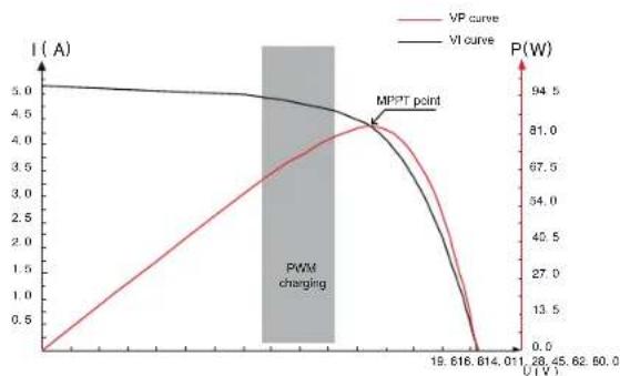
The Maximum PowerPoint Tracking (MPPT) system is an advanced charging technology with more energy output from the solar batteries by adjusting the operating state of the electrical modules. Due to nonlinearity of the solar battery array, there is a maximum power point on its curve. The PWM charging technology used in the traditional controller cannot charge the battery continuously at the point, so it cannot obtain the maximum energy of the solar panel. Instead, the solar controller with MPPT can always track the maximum power point of the array, so as to charge the battery with maximum energy. For example, for the 12V solar system, since the peak-to-peak voltage (Vpp) of the solar battery is about 17V, but the battery voltage is about 12V, therefore, when the common charge controller is charging the battery, the voltage of the solar battery is about 12V, that is, the solar battery does not fully exert its maximum power.
EN
The MPPT controller can overcome the problem and adjust the input voltage and current of the solar panel in real time to reach the maximum input power. Moreover, compared with the traditional PWM controller, it can exert the maximum power of the solar battery to provide a larger charging current. Generally speaking, it can improve the energy utilization rate by 15%\~20% than the PWM controller.
line
| U (V) | I (A) | P (W) | |-------|-------|-------| | 0 | 0 | 94.5 | | 19.618 | 4.5 | 81.0 | | 28.45 | 4.0 | 67.5 | | 62.80 | 3.5 | 42.5 | | 80.0 | 3.0 | 27.0 | | 101.0 | 2.5 | 13.5 | | 122.0 | 2.0 | 0 |Fig. 2-1 Battery panel output characteristic curve
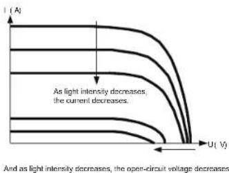
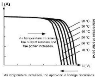
The maximum power point often changes due to the different ambient temperature and lighting conditions. And the MPPT controller is able to adjust the parameters in real-time under different conditions, thus making the system status always near the maximum operating point. The whole process is completely automatic without any adjustment.
text_image
I (A) As light intensity decreases, the current decreases. And as light intensity decreases, the open-circuit voltage decreasesFig. 2-2 Relationship between output characteristic of battery panel and light intensity
line
| Temperature (°C) | Current (A) | Open-Circuit Voltage (V) | |---|---|---| | 20 | ~1.0 | ~0.5 | | 30 | ~0.95 | ~0.45 | | 40 | ~0.9 | ~0.4 | | 50 | ~0.85 | ~0.35 | | 60 | ~0.8 | ~0.3 | | 70 | ~0.75 | ~0.25 | The chart displays a single curve representing the open-circuit voltage of each temperature. The x-axis is labeled as 'I(A)' (open-circuit voltage), and the y-axis is labeled as 'I_A' (current). The legend indicates that higher temperatures correspond to lower current values at any given open-circuit voltage. The annotation below the curve indicates that as temperature decreases, the current remains and the power increases.Fig. 2-3 Relationship between output characteristic of battery panel and temperature
03
EN
- Technical parameters
| Product model | MSC-4010 | MSC-4020 | MSC-4030 |
| Static power consumption | ≤10mA | ||
| Battery Type | SLDGEL/FLD/LIUSE/USELI, SLD as default | ||
| System voltage | 12V/24V | ||
| Battery operating voltage range | 8V-32V | ||
| Rated charging current | 10A | 20A | 30A |
| Maximum solar panel power | 130W/12V260W/24V | 260W/12V520W/24V | 400W/12V800W/24V |
| Maximum PV open-circuit voltage | 60V (55V protection, 50V recovery) | 100V (95V protection, 90V recovery) | |
| MPPT operating voltage range | (Battery voltage +2V)-45V | (Battery voltage +2V)-72V | |
| MPPT tracking efficiency | >99% | ||
| Charging conversion efficiency | 85%-98% (10%-100% of rated power) | ||
| Rated load current | 10A | 20A | |
| Load operating mode | Light control, light control + time control, manual mode (default), debugging mode, normally open | ||
| Charging current setting | √ | ||
| Full-charging setting | √ | ||
| Constant voltage output setting | √ | ||
| Charging temperature compensation of load-acid battery | √ | ||
| Temperature unit setting | √ | ||
| Overload/Short-circuit protection | √ | ||
| TTL communication | Baud rate: 9,600 bps | ||
| RS485 communication | RJ45 interface, with power output 5V/200 mA. The baud rate is 9,600 bps by default, adjustable. | ||
| Bluetooth communication | Optional | ||
| CAN communication | RJ45 interface, optional (RV-C protocol) | ||
| Historical data Save the last 200 days of historical data | |||
| Protection function | PV overvoltage protection, PV reverse connection protection, PV short-circuit protection, right reverse charging protection, input power limit protection, over-temperature protection, load short-circuit protection, overload protection, battery over-voltage/over-discharge protection, battery reverse connection protection, battery end short circuit protection. | ||
| Grounding type | Grounding of common negative electrode | ||
| Operating ambient temperature range | -35°C~65°C | ||
| Protection grade | IP32 | ||
| Cooling mode | Natural heat dissipation | ||
| Dimension | 155°98'41.7mm | 181°118'51.7mm | 187°133'72mm |
| Weight | 350g | 650g | 1200g |
04
EN
4. Charging
4.1 Charging of lead-acid battery
Select such battery types as SLD/FLD/GEL/USE, and select the appropriate system voltage.
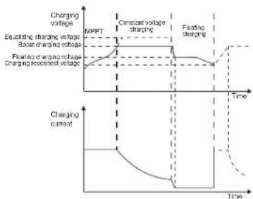
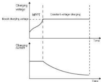
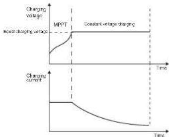
As shown in Fig. 4-1, the charging stages of lead-acid battery are: MPPT charging, constant voltage charging (equalizing/boost/floating charging), and current-limiting charging. The constant voltage charging is divided into three stages: equalizing charging, boost charging and floating charging [MPPT charging] When the battery voltage has not reached the target constant voltage value, the controller will perform MPPT charging. When the battery voltage reaches the constant voltage value, it will automatically exit MPPT charging and switch to constant voltage charging (equalizing/boosting/floating charging).
[Equalizing charging] Regular equalizing charging is good for some batteries. Equalizing charging is mainly to make the charging voltage of battery higher than the standard supplementary voltage, besides, it can vaporize the battery electrolyte to balance the battery voltage and complete relevant chemical reaction. Equalizing charging and boosting charging are not repeated during one full charging to avoid excessive gas evolution or overheating of the battery.
Notes: 1) Since the equalizing charging of floored lead-acid battery produces explosive gas, the battery compartment must be well ventilated.
2) Although the equalizing charging elevates the battery voltage, it may damage the level of sensitive DC loads, therefore, it is necessary to verify that the allowable input voltage of all loads in the system is greater than the set battery voltage value in equalizing charging.
3) Excessive charging and excessive gas evolution may damage the battery plate and cause the active substances on the battery plate to fall off. Besides, excessive high equalizing charging voltage or excessive long equalizing charging duration may damage the battery. Please set relevant parameters according to the specifications of the battery used in the system.
[Boost charging] The duration of boost charging is 2 h (default). When the duration reaches the set value, the system will switch to floating charging.
[Floating charging] Floating charging is the last constant voltage charging stage in the charging cycle of lead-acid battery. The controller keeps the charging voltage constant at the floating charging voltage. At this stage, the battery is charged with a very weak current to ensure that the battery is in full-charging. When the battery voltage is as low as the reconnect voltage of boost charging, the system will exit the floating charging stage and re-enter the next charging cycle.
4.2 Charging of lithium battery
Select such battery types as LI/USE LI, and select the system voltage from 12V/24V.
As shown in Fig. 4-2, the charging stages of lithium battery are: MPPT charging/boost charging/current-limiting charging.
[MPPT charging] When the battery voltage does not reach the target constant voltage value, the controller conducts MPPT charging to charge the battery with maximum solar power, when reaches, it automatically switches to boost charging.
[Boost charging] In the boost charging stage of lithium battery, when the battery voltage is lower than the boost charging voltage, the system conducts MPPT charging or current-limiting charging, when reaches, it switches to boost charging.
05
line
| Time Segment | Charging Voltage (MPPT) | Charging Current (constant) | | ------------ | ------------------------ | --------------------------- | | Before | High | Low | | Constant | High | Low | | After | Low | Low |Fig. 4-1 Charging curve of lead acid battery
line
| Time Point | Charging Voltage (MPPT) | Charging Current (MPPT) | Charging Voltage (Constant) | Charging Current (Constant) | | ---------- | ------------------------ | ----------------------- | --------------------------- | --------------------------- | | Start | 0 | 0 | 0 | 0 | | MPPT | 1 | 1 | 1 | 1 | | Constant | 1 | 1 | 1 | 1 | | End | 1 | 1 | 1 | 1 |Fig. 4-2 Charging curve of lithium battery
5. Battery Temperature Sampling and Control
1) Connect the temperature sensor to the corresponding temperature interface to achieve the high and low temperature protection for the battery and the temperature compensation for the charging voltage of lead-acid battery (no temperature compensation for the lithium battery); if the temperature sensor is not connected, the default temperature is 25^ C;
2). For the battery-related temperature protection/recovery value, please refer to the description in "12. System alarm". The wiring method is shown in the figure:

text_image
@mestic MPPT Solar Charge Controller BATTERY06
EN
6. Load output
1) [Recovery strategy of load short-circuit protection]:
① Automatic recovery: the self recovery time of the first protection is 10s, the second is 15s, the third is 20s, the fourth is 25s, the fifth is 30s, with more than five times restore the load output the next day;
② Manual recovery: press and hold the "SELECT" button for 2s on the system alarm interface, and the load will be recovered and output;
2) [Overload protection strategy]: 10s protection for the load greater than 1.25 times the rated load; 5s protection for the load greater than 1.5 times the rated load; 1s protection for the load greater than 2 times the rated load;
3) Please refer to "8.11-8.13" for load related settings.
- Menu
text_image
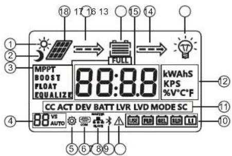
18 17 16 13 15 14 ① ② ③ ④ MPPT BOOST FLOAT EQUALIZE FULL 88:88 kWAhS KPS %V°C°F CC ACT DEV BATT LVR LVD MODE SC 88 VS AUTO ⑤ ⑥ ⑦ ⑧ ⑨| No. | Description | No. | Description |
| 1 | Daytime icon | 10 | Battery type |
| 2 | Night icon | 11 | Function character |
| 3 | Charging stage | 12 | Unit symbol |
| 4 | System voltage | 13 | Load icon |
| 5 | Parameter setting | 14 | Discharging state |
| 6 | Communication icon | 15 | Battery |
| 7 | Parallel communication Voltage/current | ||
| 8 | Bluetooth icon | 17 | Charging state |
| 9 | System alarms | 18 | Solar panel |
07
7.1 View menu
flowchart
graph TD
    A["Main menu (voltage)"] --> B["14.40 V"]
    C["Main menu (current)"] --> D["20.00 V"]
    E["Battery voltage"] --> F["12.00 V"]
    G["Charging current"] --> H["20.00 V"]
    I["System alarms"] --> J["EO"]
    K["Load mode"] --> L["15 MODE"]
    M["Battery temperature"] --> N["25.0 °C"]
    O["Device temperature"] --> P["25.0 °C"]
    Q["Operating day"] --> R["002d"]
    S["Dischargingmperethoursult/day"] --> T["0000 °A"]
    U["Discharge capacity of the day"] --> V["0000 °A"]
    W["Load Current"] --> X["20.00 °A"]
    Y["PV voltage"] --> Z["17.00 V"]
    AA["PV current"] --> AB["10.00 °C"]
    AC["Generated energy of the day"] --> AD["0000 °W"]
    AE["Dischargingmperethoursult/day"] --> AF["0000 °A"]
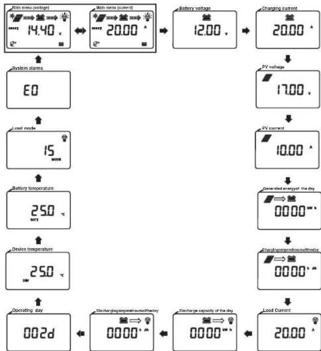
1) Alternative display between (voltage) and (current) on the main menu every 10s.
2) Short press the [SELECT] key to browse the menu. If there is no key operation for 5s, it will automatically return to the main menu.
3) Long press [ENTER] for 3s on any interface to enter the parameter setting page.
08
EN
EN
8. Parameter setting
8.1 Battery parameter list
| Battery parameters | ||||||
| Setting/Voltage\Battery Type | Sealed Lead-Acid SLD | Gel lead-acid battery GEL FLD | Flooded lead-acid battery | Lithium battery LI | Custom lead acid battery USE | Custom lithium battery USE LI |
| Overvoltage disconnect voltage^1 | 16.0V | 16.0V | 16.0V | 16.0V | Boost voltage +2V | Boost voltage +2V |
| Equalizing voltage^1 | 14.6V | - | 14.8V | -- | 9~17V | -- |
| Boost voltage^1 | 14.4V | 14.2V | 14.6V | 14.4V | 9~17V | 9~17V |
| Float charge voltage^1 | 13.8V | 13.8V | 13.8V | - | 9~17V | -- |
| Boost charging reconnect voltage^1 | 13.2V | 13.2V | 13.2V | 13.2V | 9~17V | 9~17V |
| Over-discharge restoring voltage^1 | 12.6V | 12.6V | 12.6V | 12.6V | 9~17V | 9~17V |
| Under-voltage alarming voltage^1 | 12.0V | 12.0V | 12.0V | 12.0V | 9~17V | 9~17V |
| Over-discharge voltage^1 | 11.1V | 11.1V | 11.1V | 11.1V | 9~17V | 9~17V |
| Over-discharge cutoff voltage^1 | 10.6V | 10.6V | 10.6V | 10.6V | 9~17V | 9~17V |
| Over-discharge delay | 5s | 5s | 5s | 5s | 5s | 5s |
| Equalizing charging interval | 30 days | -- | 30 days | -- | 30 days | -- |
| Equalizing charging duration | 120 min | -- | 120 min | -- | 120 min | -- |
| Boost charging duration | 120 min | 120 min | 120 min | -- | 120 min | -- |
| Temperature compensation factor mV/°C/2V | -3 | -3 | -3 | -- | -3 | -- |
| Note:1 The above values are the parameters at 25°C/12V; if it is the system of 24V/36V/48V , relevant voltage points shall be automatically multiplied by 2/3/4. | ||||||
8.2 Parameter setting list
| Function Setting range | Default | |
| Battery Type SLD/GEL/FLD/L/USE | USE LI SLD | |
| Equalizing charging voltage2 | 9V~17V Available for USE only | |
| Boost charging voltage3 | 9V~17V | Available for USE and USE LI only |
| Float charge voltage4 | 9V~17V Available for USE only | |
| Boost charging reconnect voltage5 | 9V~17V | Available for USE and USE LI only |
| Over-discharge restoring voltage6 | 9V~17V | Available for USE and USE LI only |
| Over-discharge voltage7 | 9V~17V | Available for USE and USE LI only |
| System voltage 12/24/AUTO AUTO | ||
| Charging current 0-rated current (C: no charging) Rated current | ||
| Full-charging setting 0-10 A, 0: lum the function off 0 0 | ||
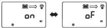
| Full-charging setting | on: constant voltage output in no load on the battery terminaloF: no output in no load on the battery terminal | oF |
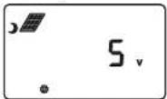
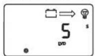
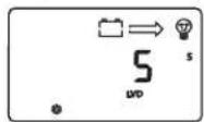
| Light control voltage8 | 5-11V | 5V |
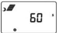
| Light control delay 60-3.600s 60s | ||
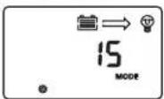
| Load mode 0-17 | 15 | |
| Load short-circuit protection | on: open load short-circuit protectionoF: close load short-circuit protection | on |
| Over-discharge delay | 1-60s | 5s |
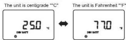
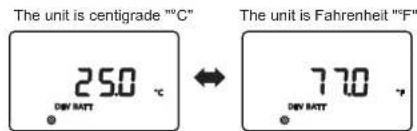
| Temperature unit | °C: Celsius/F: Fahrenheit | °C |
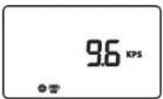
| RS485 communication baud rate | 1200~115200bps | 9600bps |
| Device address | 1-247 | 1 |
| System restart | F01 | Function key |
| Factory data reset | F02 | Function key |
| Clear historical data | F03 | Function key |
| Note:1: 24V/36V/48V battery system, automatically multiply by 2/3/4 according to the set value to get the actual control value. | ||
EN
EN
8.3 Type of battery
Please refer to "8.1 and 8.2" for setting.
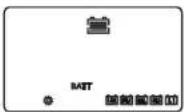
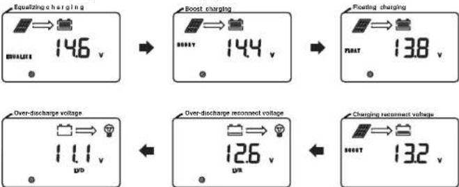
8.4 Equalizing charging\boost charging\floating charging\charging reconnect voltage\over-discharge reconnect voltage\over-discharge voltage
The option can only be set when the battery type is "USE" or "USE LI".
text_image
Equalizing charging 146 v Overdischarge voltage 111 v VD Boost charging 144 v Over-discharge reconnected voltage 126 v VD Floating charging 138 v Charging reconnected voltage 132 v8.5 System voltage
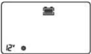
When the system voltage changes, the system voltage icon on the main page will flash, prompting the user to reboot for effective operation.
8.6 Charging current
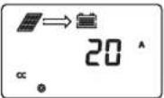
1) [No charging]: Set 0
2) [Limit charging current] Set an arbitrary value from 1 to rated charging current in steps of 1A.
EN
8.7 Full-charging setting
1) [Off]: Set 0
2) [On]: Select the appropriate current value between 1-10A
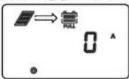
Full-charging condition: When the constant voltage charging duration of lithium battery reaches the set duration or the lead-acid battery is in float charging after the equalizing charging or the boost charging is finished, and the charging current is less than the set current value, the system will stop charging after 1 minute. and the "FULL" icon will light up on the screen.
Charging recovery condition: The battery voltage is less than the boost charging reconnect voltage, the system will recover charging, and the "FULL" icon will light off on the screen.
8.8 Constant voltage output of lead acid battery
Constant voltage output without battery
No output without battery
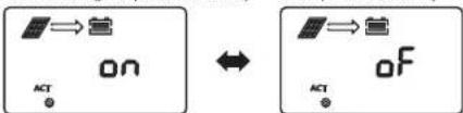
text_image
ON ACT ↔ OF ACT8.9 Light control voltage
1) [Light control on]: The solar panel voltage is less than 5V*N
2) [Light control of F]: The solar panel voltage is greater than 6V*N (N=1/2)
8.10 Light control delay
Minimum duration required to meet the light control on or off condition.
8.11 Load mode
EN
| LCD screen number | Load mode Description |
| 0 Pure light control | When the solar panel voltage is less than the Light control ON voltage with a duration is more than the light control delay, turn on the load:When the solar panel voltage is greater than the light control OFF voltage with a duration is greater than the light control delay, turn off the load. |
| 1~14 | After the duration during which the solar panel voltage is less than the light control ON voltage is greater than the light control delay, turn on the load. After the load has been operating for the set time, turn off the load.After the duration during which the solar panel voltage is greater than the light control OFF voltage is greater than the light control delay, turn off the load (light control prevails) |
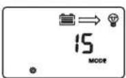
| 15 | Manual mode(default) Short press [ENTER] key to turn on/off the load (not affected by light control) |
| 16 | Debugging mode When the solar panel voltage is less than the light control ON voltage, turn on the load immediatelyWhen the solar panel voltage is greater than the light control OFF voltage, turn off the load immediately |
| 17 | Normal on mode The load is always on (in case of battery over-voltage, battery over-discharge, load short-circuit,overload,battery over-temperature, or battery low-temperature, the load will turn off the output) |
8.12 Load short-circuit protection switch
Some inductive loads or capacitive loads will produce high current at the moment of start-up, which will easily trigger load short-circuit protection, resulting in failure to turn on the load. This function can be disabled when the system cannot be started (Note: After this function is disabled, short circuit at load side of the controller is prohibited!)
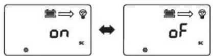
flowchart
graph LR
    A["on"] --> B["lightbulb"]
    B --> C["oF"]
    C --> D["dot symbol"]
8.13 Over-discharge delay
After the battery voltage is lower than the over-discharge voltage, the controller turns off the delay time for the load. (Note: only the type of custom battery can be set)
8.14 Temperature unit
text_image
The unit is centigrade "C" 25.0 °C DEV BATT ↔ The unit is Fahrenheit "F" 77.0 °F DEV BATT13 14
8.15 RS485 communication baud rate
The RS485 communication baud rate can be modified according to actual needs.
8.16 Equipment address
The device communication address can be modified according to actual needs.
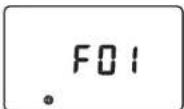
8.17 System restart
Single press [ENTER], 'F01' flashes; single press [ENTER] again, the controller will reboot.
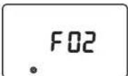
8.18 Factory reset
Reset the controller to factory default settings in accordance with "8.17".
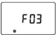
8.19 Historical data cleaning
Clear the historical data of the controller in accordance with "8.17".
EN
EN
9. TTL communication
1) Default baud rate: 9,600 bps; check bit: none; data bit: 8 bit; stop bit: 1 bit
2) Communication power supply output specification: (8.5V±1V): 100mA
| S/N | Definition |
| 1 | VCC: communication power supply output |
| 2 | RX: controller data receiving end |
| 3 | TX: controller data transmitting end |
| 4 | GND |
10.RS485
1) RS485 communication:
Default baud rate: 9,600 bps; parity bit: none; data bit: 8 bit; stop bit: 1 bit
Interface type: RJ45, communication power supply output specification: 5V/200mA
2) RJ45 interface communication line sequence definition:
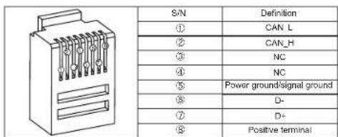
text_image
S/N Definition ① CAN_L ② CAN_H ③ NC ④ NC ⑤ Power ground/signal ground ⑥ D- ⑦ D+ ⑧ Positive terminalNote: NC represents an empty pin, which means that the pin is not connected.
11. CAN communication(Optional)
1) CAN communication: support RV-C protocol
12. Key
[Select]: short press to switch browsing menu and set data increment;
Press and hold the "System Alarm" Interface for 2s to clear the "Load Short Circuit/
Overload Protection" fault code.
[Enter]: press and hold for 3s to enter/exit parameter setting;
Short press: short press on/off load in menu browsing interface (manual mode);
In the setting menu interface, short press for parameter modification and confirmation.
EN
13. System alarms
| System alarms | Meaning | Description |
| E0 | Normal system | No action |
| E1 Battery over-discharge | Turn off load output, after the battery voltage rises to the over-discharge reconnect voltage, relieve over-discharge to restore load output | |
| E2 Battery over-voltage | Stop charging, check and find out the cause of high battery voltage. The charging will be automatically restored after the battery voltage is lowered | |
| E3 | Battery under-voltage warning | Battery voltage below the under-voltage warning threshold, warning only |
| E4 | Load short-circuited Turn off load output | |
| E5 Load over-current | Turn off load output, and perform delay protection by a multiple of rated current | |
| E6 | Over-temperature protection of device | When the internal temperature is higher than the set temperature, start the constant temperature control; Charging is prohibited when the temperature is higher than 75°C, and charging is resumed when the temperature is lower than 75°C. |
| E7 | Battery over-temperature protection | Charging will be stopped when the battery temperature is above 65°C, and automatically resumed when it is below 60°C. |
| E10 Solar panel over-voltage | Charging is stopped, and then automatically resumed when the solar panel voltage is below the safety limit | |
| E15 Lead acid battery is not connected | In lead-acid battery mode, the battery is damaged or not connected. | |
| E16 | Battery high temperature discharging protection | Load output will be turned off when the battery temperature is above 75°C and resumed when it is below 70°C. |
| E17 | Battery low temperature discharging protection | Load output will be turned off when the battery temperature is below -35°C and resumed when it is above -30°C |
| E18 | Overcharge protection | Charging is stopped and then resumed 10s after the battery voltage is lowered |
| E19 | Battery low temperature charging protection | Charging will be stopped when the battery temperature is below -35°C and resumed when it is above -30°C |
| E30 | Charging and discharging disabled by system setting | Off by default (set relevant registers by protocol) |
| E31 | Charging overvoltage, overcurrent and reverse current protection etc. | After the abnormal conditions are removed, the equipment will recover automatically |
EN
- Common problems and solutions
| Phenomenon Troubleshooting | |
| LCD screen does not light up | Check whether the battery and solar panel are properly connected and whether the LCD connection cable has a poor connection |
| There is voltage in the solar panel, there is no voltage output from the battery side, and code E1/E15 is displayed | The battery is not detected at the lead-acid battery end, there is no voltage output from both ends of the battery. Connect the battery to return to normal or turn on the lead-acid battery activation switch |
| 12V/24V/36V/48V normal voltage battery is connected, the battery icon on the LCD screen flashes slowly, and code E1 is displayed | Check the battery system voltage, or set it to automatic identify and reboot the controller |
| The system voltage 12V/24V/36V/48V icon on the screen flashes | Set system voltage change, prompting the user to reboot the system for the change to take effect |
| The controller fails to charge | Check whether there is wrong wiring, whether the solar panel voltage exceeds the rated value, whether the battery is over-voltage, whether the LCD screen displays any error code of internal over-temperature, external over-temperature, external lithium battery low temperature, or lead-acid battery open-circuit, and whether it displays E7/E10, etc. |
| Charging power does not reach the rated value | Perform system current limiting and thermostatic control; Check to see if the system has reset charging current |
| Other problems or exceptions difficult to resolve | Try to reboot (F01) or reset controller (F02), and reset relevant parameters again as per system configurations. Be careful |
| Fail to start some loads | Try enabling the load short-circuit function after checking that the wiring is correct |
| The screen displays "full", and charging stops | Charging stops as the charging cut-off current conditions are met. When the voltage is below the boost charging reconnect voltage, the charging will be automatically resumed |
| There is a system alarm code See "12. System alarms" for details | |
15. Product Installation
15.1 Installation precautions
Be careful when installing battery. Wear protective goggles when installing a flooded lead-acid battery. Once in contact with the battery acid, please rinse with water immediately.
◆ Keep away from metal objects to prevent short-circuit of battery.
The battery may produce acid gas when charging. Make sure that the ambient environment is well-ventilated.
◆ The battery may produce combustible gas. Stay away from sparks.
When installing outdoors, avoid direct sunlight and rain seeping.
The falsely connected connection points and corroded wires may cause great heat, melt the wire insulation, burn the surrounding materials, and even cause fire. Therefore, it is necessary to ensure that all connectors are tightened, and the wires are preferably fixed with ties to avoid shaking of the wires during mobile applications loose connector.
EN
When connecting the system, the output voltage of the components may exceed the human body safety voltage, therefore, use insulated tools and keep your hands dry.
The battery terminals on the controller can be connected either to a single battery or a battery pack. The subsequent instructions are for a single battery, but they are also applicable to systems with a battery pack.
◆ Please follow the safety recommendations of the battery manufacturer.
◆ The system connection cables selected shall have a current density ≤4A/mm².
◆ Ground the ground terminal of the controller.
When installing the battery, it is forbidden to reverse the battery connection, which may cause irreversible damage.
15.2 Installation steps
Wiring and installation must meet the requirements of national and local electrical codes. Wiring specifications shall be selected according to the rated current, generally, 5 A/mm ^2 .
Step 1: Select an installation location
Do not install the controller in a place with direct sunlight, high temperature, or where water can easily enter, and make sure the controller is well ventilated.
Step 2: Fix suspension screws
Mark the mounting position according to the mounting dimensions of the controller, drill two mounting holes of suitable size at the two marks and fix the screws on the two mounting holes.
Step 3: Fix the controller
Align the controller fixing holes with the two pre-fixed screws to hang the controller up, and then fix the two screws below.
Step 4: Open the front cover of the controller, wire, and then close the front cover.
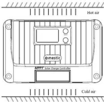
text_image
Hot air @mestic MPPT Solar Charge Controller Cold airEN
16. Protection Functions
◆ Over-temperature protection of device
When the internal temperature of the controller exceeds the set value, the charging power will be automatically lowered or the charging will even be stopped, further slowing the rise in internal temperature of the controller.
◆ Battery over-temperature protection
Battery over-temperature protection requires an external battery temperature sampling sensor. Charging will be stopped when the battery temperature is detected to be too high, and will be automatically resumed when the battery temperature drops to 5°C below the set value for 2s.
◆ Input over-power protection
When the battery panel power is greater than the rated power, the controller will limit the charging power within the rated power range to prevent excessive current from damaging to the controller, and the controller will enter current-limited charging.
◆ PV input side too high voltage protection
When the voltage at the input side of the PV array is too high, the controller will automatically cut off PV input.
◆ PV input reverse-connection protection
The controller will not be damaged if the polarity of the PV array is reversed and will return to normal after the wiring error is corrected.
◆ Reverse charging protection at night
Prevent the battery from discharging through solar battery at night.
17. System Maintenance
In order to maintain the optimal operating performance of the controller for a long time, it is recommended that the following items are regularly checked.
Make sure that the airflow around the controller is not blocked, and remove any dirt or debris from the radiator.
◆ Take corrective actions timely after any fault or error is found.
◆ Check whether there is corrosion, insulation damage, high temperature or burning/discoloring at terminals, case distortion, etc., and repair or replace timely if any.
◆ Check whether there is any exposed or broken wire or wire with poor insulation, and repair or replace timely if any.
◆ Check whether there is dirt, nesting insects or corrosion, and clean timely if any.
Warning: There is a risk of electrical shock! Before carrying out checks or operations above, make sure that all power supplies for the controller are disconnected!
Any non-professional personnel is prohibited from carrying out such operations.
EN
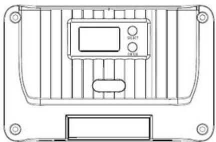
18. Product Dimensions
18.1 MSC-4010
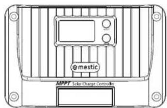
text_image
@mestic MPPT Solar Charge Controller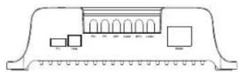
18.2 MSC-4020
text_image
@mestic MPPT Solar Charge Controller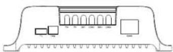
Model: MSC-4010
Product dimension: 155*99*41.7mm
Mounting hole spacing: 137*77mm
Fixed hole position: φ4.5mm
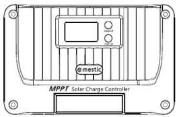
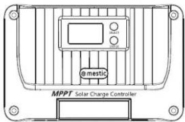
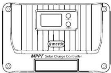
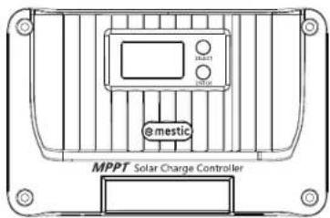
Model: MSC-4020
Product dimension: 181*118*61.7mm
Mounting hole spacing: 161*96mm
Fixed hole position: φ4.5mm
18.3 MSC-4030
text_image
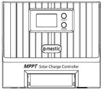
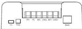
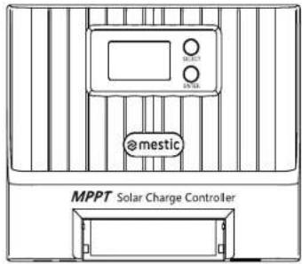
atmestic MPPT Solar Charge ControllerModel: MSC-4030
Product dimension: 187*133*72mm
Mounting hole spacing: 174*100mm
Fixed hole position: φ5mm
text_image
T1 Temp. PS+ PS- BAT- LOAD- BAT+ Load+ Re400- Bedradingsschema systeem
19.1 Bedradingsschema systeem
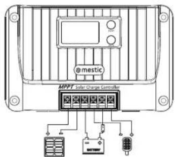
text_image
@mestic MPPT Solar Charge Controller21 22
EN
mestic
EN
Solar charge controller MPPT MSC-4010/-4020/-4030
Made in P.R.C - Imported by
Protection of the environment
This symbol attached to the product means that it is an appliance whose disposal is subject to the directive on waste from electrical and electronic equipment (WEEE). This appliance may not in any way be treated as household waste and must be subject to a specific type of removal for this type of waste. Recycling and recovery systems are available in your area (waste removal) and by distributors. By taking your appliance at its end of life to a recycling facility, you will contribute to environmental conservation and prevent any harm to your health.

mestic®
Solarladeregler MPPT MSC-4010/-4020/-4030


natural_image
Technical line drawing of a mechanical component with no visible text or symbolsRelax... it's mestic
User instructions EN
line
| U (V) | I (A) - VP curve | I (A) - VI curve | P (W) | |-------|------------------|------------------|-------| | 0 | 0.0 | 5.0 | 94.5 | | 19.6 | 4.5 | 4.5 | 81.0 | | 28.4 | 0.0 | 0.0 | 0.0 | | 62.0 | 0.0 | 0.0 | 0.0 | | 80.0 | 0.0 | 0.0 | 0.0 |line
| Time Point | Charging Voltage (MPPT) | Charging Current (constant) | | ---------- | ------------------------ | --------------------------- | | Before MPPT | 0 | 0 | | Constant | 1 | 0 | | After MPPT | 1 | 0 |text_image
ON ACT ↔ OF ACTtext_image
Hot air emestic MPPT Solar Charge Controller Cold airDE
text_image
@mestic MPPT Solar Charge Controller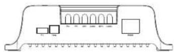
18.2 MSC-4020

text_image
@mestic MPPT Solar Charge Controller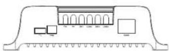
Model: MSC-4010
Produktabmessungen: 155*99*41.7mm
text_image
atmestic MPPT Solar Charge Controller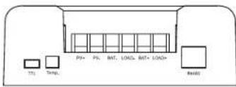
text_image
T1 Treg. PS+ PS- BAT- LOAD- BAT+ LOAD+ ReadModel: MSC-4030
Produktabmessungen:
187*133*72mm
text_image
@mestic MPPT Solar Charge Controller21 22
DE
mestic
DE
Solarladeregler MPPT MSC-4010/-4020/-4030
natural_image
Technical line drawing of a mechanical component with no visible text or symbolsRelax... it's mestic
User instructions EN
line
| U (V) | I (A) | P (W) | | ----------- | ----- | ----- | | 19.616 | 0.0 | 0.0 | | 20.0 | 5.0 | 94.5 | | 20.45 | 4.5 | 81.0 | | 20.8 | 4.0 | 67.5 | | 21.2 | 3.5 | 54.0 | | 21.6 | 3.0 | 42.5 | | 22.0 | 2.5 | 34.0 | | 22.4 | 2.0 | 27.0 | | 22.8 | 1.5 | 20.0 | | 23.2 | 1.0 | 13.5 | | 23.6 | 0.5 | 0.0 |line
| Temperature (°C) | Current (V) at 20°C | Current (V) at 30°C | Current (V) at 40°C | Current (V) at 50°C | Current (V) at 60°C | Current (V) at 70°C | | ---------------- | ------------------- | ------------------- | ------------------- | ------------------- | ------------------- | ------------------- | | 20 | ~1.0 | ~1.0 | ~1.0 | ~1.0 | ~1.0 | ~1.0 | | 30 | ~0.8 | ~0.8 | ~0.8 | ~0.8 | ~0.8 | ~0.8 | | 40 | ~0.6 | ~0.6 | ~0.6 | ~0.6 | ~0.6 | ~0.6 | | 50 | ~0.4 | ~0.4 | ~0.4 | ~0.4 | ~0.4 | ~0.4 | | 60 | ~0.2 | ~0.2 | ~0.2 | ~0.2 | ~0.2 | ~0.2 | | 70 | ~0.1 | ~0.1 | ~0.1 | ~0.1 | ~0.1 | ~0.1 |line
| Time | MPPT Charging Voltage | Constant Voltage Charging | Floating Charging Voltage | Floating Charging Voltage | |------|------------------------|----------------------------|----------------------------|----------------------------| | 0 | 0 | 0 | 0 | 0 | | 1 | 1 | 1 | 0 | 0 | | 2 | 2 | 2 | 0 | 0 | | 3 | 3 | 3 | 0 | 0 | | 4 | 4 | 4 | 0 | 0 | | 5 | 5 | 5 | 0 | 0 | | 6 | 6 | 6 | 0 | 0 | | 7 | 7 | 7 | 0 | 0 | | 8 | 8 | 8 | 0 | 0 | | 9 | 9 | 9 | 0 | 0 | | 10 | 10 | 10 | 0 | 0 | | 11 | 11 | 11 | 0 | 0 | | 12 | 12 | 12 | 0 | 0 | | 13 | 13 | 13 | 0 | 0 | | 14 | 14 | 14 | 0 | 0 | | 15 | 15 | 15 | 0 | 0 | | 16 | 16 | 16 | 0 | 0 | | 17 | 17 | 17 | 0 | 0 | | 18 | 18 | 18 | 0 | 0 | | 19 | 19 | 19 | 0 | 0 | | 20 | 20 | 20 | 0 | 0 | | 21 | 21 | 21 | 0 | 0 | | 22 | 22 | 22 | 0 | 0 | | 23 | 23 | 23 | 0 | 0 | | 24 | 24 | 24 | 0 | 0 | | 25 | 25 | 25 | 0 | 0 | | 26 | 26 | 26 | 0 | 0 | | 27 | 27 | 27 | 0 | 0 | | 28 | 28 | 28 | 0 | 0 | | 29 | 29 | 29 | 0 | 0 | | 30 | 30 | 30 | 0 | 0 | | 31 | nan | nan | nan | nan | | Peak (Time) - MPPT: = Time (approx.) | | Peak (Time) - Constant Voltage Charging Voltage: = Time (approx.) | | Peak (Time) - Floating Charging Voltage Charging Reconnected Voltage: = Time (approx.) | | Peak (Time) - Charging Current: = Time (approx.) | | Peak (Time) - Constant Voltage Charging Voltage + Freezing Charging Voltage: = Time (approx.) | | Peak (Time) - Floating Charging Voltage Charging Reconnected Voltage: = Time (approx.) | | Peak (Time) - Charging Current: = Time (approx.) | | Peak (Time) - Constant Voltage Charging Voltage Charging Current: = Time (approx.) | | Peak (Time) - Floating Charging Voltage Charging Current Reconnected Voltage: = Time (approx.) | | Peak (Time) - Charging Current: = Time (approx.) | | Peak (Time) - Constant Voltage Charging Voltage Charging Current Reconnected Voltage: = Time (approx.) | | Peak (Time) - Floating Charging Voltage Charging Current Reconnected Voltage: = Time (approx.) | | Peak (Time) - Charging Current: = Time (approx.) | | Peak (Time) - Constant Voltage Charging Current Charging Current Reconnected Voltage: = Time (approx.) | | Peak (Time) - Floating Charging Current Charging Current Reconnected Voltage: = Time (approx.) | | Peak (Time) - Charging Current: = Time (approx.) | | Peak (Time) - Constant Voltage Charging Current Charging Current Reconnected Voltage: = Time (approx.) | | Peak (Time) - Floating Charging Current Charging Current Reconnected Voltage: = Time (approx.) | | Peak (Time) - Charging Current: = Time (approx.) | | Peak (Time) - Constant Voltage Charging Current Charging Current Reconnected Language: = Time (approx.) | | Peak (Time) - Floating Charging Current: = Time (approx.) | | Peak (Time) - Charging Current: = Time (approx.) | | Peak (Time) - Constant Voltage Charging Current Charging Current Reconnected Language: = Time (approx.) | | Peak (Time) - Floating Charging Current: = Time (approx.) | | Peak (Time) - Charging Current: = Time (approx.) | | Peak (Time) - Constant Voltage Charging Current Charging Current Reconnected Language: = Time (approx.) | | Peak [Time] - Constant Voltage Charging Current Charging Current Reconnected Language: = Time (approx.) | | Peak [Time] - Floating Charging Current: = Time (approx.) | | Peak [Time] - Charging Current: = Time (approx.) | | Peak [Time] - Constant Voltage Charging Current Charging Current Reconnected Language: = Time (approx.) | | Peak [Time] - Floating Charging Current: = Time (approx.) | | Peak [Time] - Charging Current: = Time (approx.) | | Peak [Time] - Constant Voltage Charging Current Charging Current Reconnected Language: = Time (approx.) | | Peak [Time] - Floating Charging Current: = Time (approx.) | | Peaks [Time] - Charging Current: = Time (approx.) | | Peaks [Time] - Constant Voltage Charging Current Charging Current Reconnected Language: = Time (approx.) | | Peaks [Time] - Floating Charging Current: = Time (approx.) | | Peaks [Time] - Charging Current: = Time (approx.) | | Peaks [Time] - Constant Voltage Charging Current Charging Current Reconnected Language: = Time (approx.) | | Peaks [Time] - Floating Charging Current: = Time (approx.) | | Peaks [Time] - Charging Current: = Time (approx.) | | Peaks [Time] - Constant Voltage Charging Current Charging Current Reconnected Language: = Timescale for each of the cycle, where 'constant' is the value of 'constant voltage charging'.line
| Time Point | Charging Voltage (MPPT) | Charging Current (constant) | | ---------- | ------------------------ | --------------------------- | | Start | 0 | 0 | | Peak | 1 | 1 | | Constant | 1 | 0 |flowchart
graph TD
    A["Main menu (voltage)"] --> B["14.40 V"]
    C["Main menu (current)"] --> D["20.00 V"]
    B --> E["Battery voltage"]
    D --> E
    E --> F["Charging current"]
    F --> G["20.00 V"]
    G --> H["PV voltage"]
    H --> I["17.00 V"]
    I --> J["PV current"]
    J --> K["10.00 V"]
    K --> L["Generated energy of the day"]
    L --> M["00.00 W·h"]
    M --> N["Charging temperature/day"]
    N --> O["00.00 W·h"]
    O --> P["Load Current"]
    P --> Q["20.00 V"]
    Q --> R["Discharge capacity of the day"]
    R --> S["00.00 W·h"]
    S --> T["Operating day"]
    T --> U["002d"]
    U --> V["Discharging temperature/day"]
    V --> W["00.00 W·h"]
8.4 Equalizing charging\boost charging\floating charging\charging
reconnect voltage\over-discharge reconnect voltage\over-discharge voltage
text_image
Equalizing charging 146 v Boost charging 144 v Floating charging 138 v Over-discharge voltage 111 v Over-discharge reconnected voltage 126 v Charging reconnected voltage 132 v8.5 Système Tension
text_image
ON ACT ↔ OF ACTtext_image
@mestic MPPT Solar Charge Controller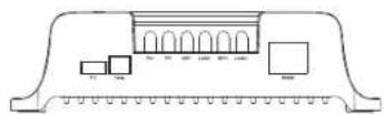
18.2 MSC-4020
text_image
@mestic MPPT Solar Charge Controller
Modèle : MSC-4010
text_image
@mestic MPPT Solar Charge Controllertext_image
@mestic MPPT Solar Charge Controller21 22
FR

mestic®
natural_image
Technical line drawing of a mechanical or electrical component with no visible text, numbers, or symbols.Relax... it's mestic
User instructions EN
line
| Time (s) | I (A) VP curve | I (A) VI curve | P (W) VP curve | P (W) VI curve | |----------|----------------|----------------|----------------|----------------| | 0 | 0.0 | 5.0 | 0.0 | 94.5 | | 19.616 | 4.5 | 4.5 | 27.0 | 81.0 | | 28.45 | 4.0 | 4.0 | 42.5 | 67.5 | | 62.80 | 3.5 | 3.5 | 67.5 | 54.0 | | 80.0 | 3.0 | 3.0 | 81.0 | 42.5 |line
| Time Segment | Charging Voltage (MPPT) | Charging Current (MPPT) | Charging Voltage (Constant Voltage) | Charging Current (Constant Voltage) | |--------------|--------------------------|--------------------------|-------------------------------------|-------------------------------------| | Start | 0 | 0 | 0 | 0 | | Peak | 100 | 0 | 100 | 0 | | Constant | 0 | 100 | 0 | 100 | | Floating | 0 | 0 | 0 | 0 | | End | 0 | 0 | 0 | 0 |line
| Time | Charging voltage | Charging current | |------|------------------|------------------| | 0 | Low | High | | MPPT | Constant | Constant | | End | Constant | Constant |flowchart
graph TD
    A["7.1 Ver el menü"] --> B["With menu (voltage)"]
    A --> C["With menu (current)"]
    B --> D["14.40 V"]
    C --> E["20.00 V"]
    D --> F["Battery voltage: 12.00 V"]
    E --> G["Battery voltage: 12.00 V"]
    F --> H["Charging current: 20.00 V"]
    G --> I["Charging current: 20.00 V"]
    H --> J["PV voltage: 17.00 V"]
    I --> K["PV current: 17.00 V"]
    J --> L["Load mode: 15 m/s"]
    K --> M["Load mode: 15 m/s"]
    L --> N["Battery temperature: 250 mC"]
    M --> O["Battery temperature: 250 mC"]
    N --> P["Device temperature: 250 mC"]
    O --> Q["Device temperature: 250 mC"]
    P --> R["Operating day: 002d"]
    Q --> S["Operating day: 002d"]
    R --> T["Discharging pump/ounm/day: 0000 m³/h"]
    S --> U["Discharging pump/ounm/day: 0000 m³/h"]
    T --> V["Discharge capacity of the day: 0000 m³/h"]
    U --> W["Discharge capacity of the day: 0000 m³/h"]
    V --> X["Load Current: 20.00 V"]
    W --> Y["Load Current: 20.00 V"]
8.4 Equalizing charging\boost charging\floating charging\charging reconnect voltage\over-discharge reconnect voltage\over-discharge voltage
text_image
Equalizing charging 146 v Boost charging 144 v Floating charging 138 v Over-discharge voltage 111 v Over-discharge reconnected voltage 126 v Charging reconnected voltage 132 v8.5 Sistema tensión
text_image
ON ACT ↔ OF ACTflowchart
graph LR
    A["on sc"] --> B["off sc"]
    B --> C["Output"]
text_image
@mestic MPPT Solar Charge Controller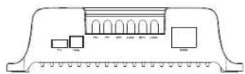
18.2 MSC-4020
text_image
@mestic MPPT Solar Charge Controller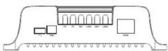
Model: MSC-4010
text_image
@mestic MPPT Solar Charge Controller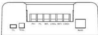
text_image
T1 Temp. PS+ PS- BAT- LOAD- BAT+ LOAD+ Loadtext_image
@mestic MPPT Solar Charge Controller21 22
ES
mestic
ES
Controlador de carga solar MPPT MSC-4010/-4020/-4030
natural_image
Technical line drawing of a mechanical component with no visible text or symbolsRelax... it's mestic
User instructions EN
line
| Time (s) | I (A) VP curve | I (A) VI curve | P(W) VP curve | P(W) VI curve | |----------|----------------|----------------|---------------|---------------| | 0 | 0.0 | 5.0 | 94.5 | 94.5 | | 19.616 | 4.5 | 4.5 | 81.0 | 81.0 | | 28.456 | 3.5 | 3.5 | 67.5 | 67.5 | | 62.80 | 2.5 | 2.5 | 42.0 | 42.0 | | 80.0 | 1.5 | 1.5 | 27.0 | 27.0 | | Final | 0.0 | 0.0 | 0.0 | 0.0 |text_image
I (A) Al diminuire bell-intensilla lumhoss, Is corrente diminusce. U (V)line
| Time Segment | Charging Voltage (MPPT) | Charging Current (MPPT) | Charging Voltage (Constant) | Charging Voltage (Floating) | Charging Current (Floating) | |--------------|--------------------------|--------------------------|-------------------------------|-------------------------------|----------------------------| | 0 | 0 | 0 | 0 | 0 | 0 | | Peak | 100 | 0 | Constant | 0 | 0 | | Low | 0 | 0 | Constant | 0 | 0 | | High | 0 | 0 | Constant | 0 | 0 |flowchart
graph TD
    A["Main menu (voltage)"] --> B["14.40 V"]
    C["Main menu (current)"] --> D["20.00 V"]
    B --> E["Battery voltage"]
    D --> E
    E --> F["Charging current"]
    F --> G["20.00 V"]
    G --> H["PV voltage"]
    H --> I["17.00 V"]
    I --> J["PV current"]
    J --> K["10.00 V"]
    K --> L["Generated energy of the day"]
    L --> M["00.00 V*"]
    M --> N["Charging power output/day"]
    N --> O["00.00 V*"]
    O --> P["Discharge capacity of the day"]
    P --> Q["00.00 V*"]
    Q --> R["Load Current"]
    R --> S["20.00 V"]
    S --> T["Operating day"]
    T --> U["002d"]
    U --> V["Discharging power output/day"]
    V --> W["00.00 V*"]
    W --> X["Discharge capacity of the day"]
text_image
Equalizing charging 146 v Boost charging 144 v Floating charging 138 v Over-discharge voltage 111 v Over-discharge reconnect voltage 126 v Charging reconnect voltage 132 vSome inductive loads or capacitive loads will produce high current at the moment of start-up, which will easily trigger load short-circuit protection, resulting in failure to turn on the load. This function can be disabled when the system cannot be started (Note: After this function is disabled, short circuit at load side of the controller is prohibited!)
flowchart
graph LR
    A["ON"] --> B["Lightbulb"]
    B --> C["OF"]
8.13 Over-discharge delay
After the battery voltage is lower than the over-discharge voltage, the controller turns off the delay time for the load. (Note: only the type of custom battery can be set)
8.14 Temperature unit
text_image
The unit is centigrade "°C" 250 °C ↔ The unit is Fahrenheit "F" 770 °C DEV BATT DEV BATT13 14
IT
Note: NC represents an empty pin, which means that the pin is not connected.
text_image
@mestic MPPT Solar Charge Controller
18.2 MSC-4020
text_image
@mestic MPPT Solar Charge Controller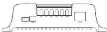
Model: MSC-4010
text_image
@mestic MPPT Solar Charge Controller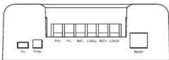
text_image
T1 Temp. P9+ P5 BAT LOAD BAT+ LOAD+ Loadtext_image
@mestic MPPT Solar Charge Controller21 22
IT

mestic®
natural_image
Technical line drawing of a mechanical or electrical component with no visible text, numbers, or symbols.Relax... it's mestic
User instructions EN
line
| Time (s) | I (A) VP curve | I (A) VI curve | P (W) VP curve | P (W) VI curve | |----------|----------------|----------------|----------------|----------------| | 0 | 0.0 | 5.0 | 0.0 | 94.5 | | 19.616 | 4.5 | 4.5 | 81.0 | 81.0 | | 28.456 | 3.5 | 3.5 | 67.5 | 67.5 | | 62.80 | 2.5 | 2.5 | 42.0 | 42.0 | | 80.0 | 1.5 | 1.5 | 27.0 | 27.0 | | Final | 0.0 | 0.0 | 0.0 | 0.0 |Fig. 2-1 Karakteristisk curve for batteripanelets output
line
| Time Segment | Charging Voltage (MPPT) | Charging Current (FEEP) | | ------------ | ------------------------ | ----------------------- | | Before | 0 | 0 | | Constant | High | 0 | | Floating | Low | Low | | After | High | Low |line
| Time | Charging voltage (MPPT) | Charging current | |------|--------------------------|------------------| | 0 | 0 | 0 | | Peak | 1 | 1 | | Constant | 1 | 0 |Fig. 4-2 Opladningskurve for litiumbatteri
text_image
Equalizing charging 146 v EVALUE Boost charging 144 v Floating charging 138 v Over-discharge voltage 111 v U/D Over-discharge reconnect voltage 126 v U/R Charging reconnect voltage 132 v8.5 System spending
text_image
ON ACT ↔ OF ACIflowchart
graph LR
    A["ON on sc"] --> B["OF on sc"]
8.13 Overafladning forsinkelse
14.Common problems and solutions
text_image
@mestic MPPT Solar Charge Controller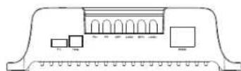
Model: MSC-4010
Produktdimension: 155*99*41,7mm
Afstand mellem monteringshuller:137*77mm
Fast hulposition: φ4.5mm
18.2 MSC-4020
text_image
@mestic MPPT Solar Charge Controller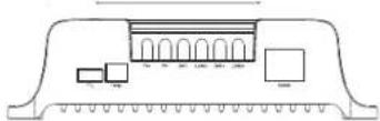
Model: MSC-4020
Produktdimension: 181*118*61,7mm
Afstand mellem monteringshuller: 161*96mm
Fast hulposition: φ4.5mm
18.3 MSC-4030
text_image
atmestic MPPT Solar Charge Controller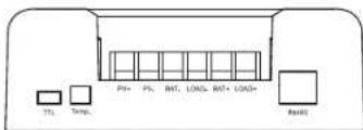
text_image
T1 Temp. PS+ PS- BAT- LOAD- BAT+ LOAD+ ResidModel: MSC-4030
Produktdimension: 187*133*72mm
Afstand mellem monteringshuller:174*100mm
Fast hulposition:φ5mm
19. Ledningsdiagram for systemet
19.1 Ledningsdiagram for systemet
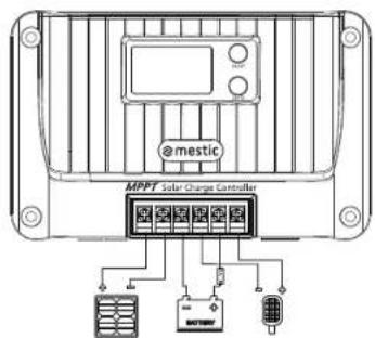
text_image
@mestic MPPT Solar Charge Controller21 22
DK

mestic®
DK
Solar laderegulator MPPT MSC-4010/-4020/-4030
natural_image
Technical line drawing of a mechanical component with no visible text or symbolsRelax... it's mestic
User instructions EN
line
| Time (s) | I (A) - VP curve | I (A) - VI curve | P (W) | | -------- | ---------------- | ---------------- | ----- | | 0 | 0.0 | 5.0 | 94.5 | | 19.616 | 4.5 | 4.5 | 81.0 | | 28.456 | 3.5 | 3.5 | 67.5 | | 62.80 | 2.5 | 2.5 | 42.0 | | 80.0 | 1.5 | 1.5 | 27.0 | | 108.0 | 0.5 | 0.5 | 13.5 |line
| Time Segment | Charging Voltage (MPPT) | Charging Current (FEEP) | | ------------ | ------------------------ | ----------------------- | | Before | 0 | 0 | | Constant | High | 0 | | After | Low | Decreasing |line
| Time | Charging voltage | Charging current | |------|------------------|------------------| | 0 | Low | High | | MPPT | Constant | Constant | | End | Constant | Constant |flowchart
graph TD
    A["Main menu (voltage)"] --> B["14.40 V"]
    C["Main menu (current)"] --> D["20.00 V"]
    B --> E["Battery voltage"]
    D --> E
    E --> F["Charging current"]
    F --> G["20.00 V"]
    G --> H["PV voltage"]
    H --> I["17.00 V"]
    I --> J["PV current"]
    J --> K["10.00 V"]
    K --> L["Generated energy of the day"]
    L --> M["00.00 V*"]
    M --> N["Charging power output/day"]
    N --> O["00.00 V*"]
    O --> P["Discharge capacity of the day"]
    P --> Q["00.00 V*"]
    Q --> R["Load Current"]
    R --> S["20.00 V"]
    S --> T["Operating day"]
    T --> U["002d"]
    U --> V["Discharging power output/day"]
    V --> W["00.00 V*"]
    W --> X["Discharge capacity of the day"]
text_image
Equalizing charging 146 v Boost charging 144 v Floating charging 138 v Over-discharge voltage 111 v Over-discharge reconnect voltage 126 v Charging reconnect voltage 132 v8.5 System spänning
text_image
ON ACT ↔ OF ACT8.9 L jusstyrning spänning
flowchart
graph LR
    A["ON on sc"] --> B["OF on sc"]
text_image
@mestic MPPT Solar Charge Controller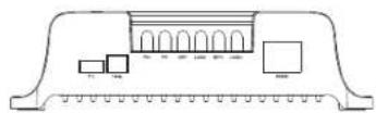
18.2 MSC-4020
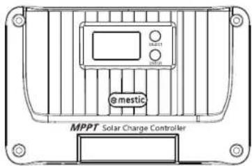
text_image
@mestic MPPT Solar Charge Controller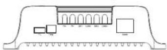
Model: MSC-4010
Produktdimension: 155*99*41,7mm
text_image
@mestic MPPT Solar Charge Controller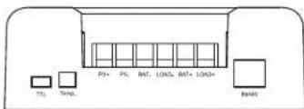
text_image
T1 Temp PS+ PS- BAT- LOAD- BAT+ LOAD+ ResistModel: MSC-4030
Produktdimension: 187*133*72mm
Avstånd mellan monteringshål: 174*100mm
Fast halposition: φ5mm
- System wiring diagram
18.1 System wiring diagram

text_image
@mestic MPPT Solar Charge Controller21 22
SE

mestic
SE
Solar laddningsregulator MPPT MSC-4010/-4020/-4030
natural_image
Technical line drawing of a mechanical or electrical component with no visible text, numbers, or symbols.Relax... it's mestic
User instructions EN
line
| Current (A) | VP curve (A) | VI curve (A) | P(W) | |-------------|--------------|--------------|------| | 0 | 0 | 5.0 | 94.5 | | 19.616 | 4.5 | 4.5 | 81 | | 28.45 | 3.5 | 3.5 | 67.5 | | 62.8 | 2.5 | 2.5 | 42.5 | | 80.0 | 1.5 | 1.5 | 27 |line
| Time Segment | Charging Voltage (MPPT) | Charging Current (FEEP) | | ------------ | ------------------------ | ------------------------ | | Before | 0 | 0 | | Constant | High | Low | | Floating | Low | Low | | After | High | Low |Fig. 4-1 Ladckurve for blybatteri
line
| Time | Charging voltage | Charging current | |------|------------------|------------------| | 0 | Low | High | | MPPT | Constant | Constant | | End | Constant | Constant |Fig. 4-2 Ladekurve for litiumbatteri
flowchart
graph TD
    A["Main menu (voltage)"] --> B["14.40 V"]
    C["Main menu (current)"] --> D["20.00 V"]
    B --> E["Battery voltage"]
    D --> E
    E --> F["Charging current"]
    F --> G["20.00 V"]
    G --> H["PV voltage"]
    H --> I["17.00 V"]
    I --> J["PV current"]
    J --> K["10.00 V"]
    K --> L["Generated energy of the day"]
    L --> M["00.00 V*"]
    M --> N["Charging temperature"]
    N --> O["Device temperature"]
    O --> P["25.0 V"]
    P --> Q["Operating day"]
    Q --> R["002d"]
    R --> S["Discharging temperature"]
    S --> T["Discharge capacity of the day"]
    T --> U["Load Current"]
NO
text_image
Equalizing charging 14.6 v Boost charging 14.4 v Floating charging 13.8 v Over-discharge voltage 11.1 v Over-discharge reconnected voltage 12.6 v Charging reconnected voltage 13.2 v8.5 System spenning
text_image
ON ACT ↔ OF ACT8.11 Last inn -modus
NO
text_image
@mestic MPPT Solar Charge Controller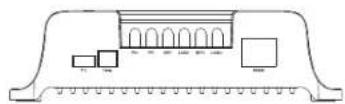
Model: MSC-4010
Produktdimensjon: 155 * 99 * 41,7 mm
Avstand mellom monteringshull: 137 *77 mm
text_image
@mestic MPPT Solar Charge Controller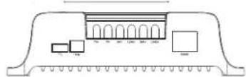
Model: MSC-4020
Produktdimensjon: 181 * 118 * 61,7mm
Avstand mellom monteringshall: 161 * 96 mm
text_image
atmestic MPPT Solar Charge Controller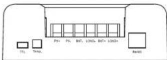
text_image
T1 Temp PS PS BAT LOAD BAT+ LOAD+ ReadModel: MSC-4030
Produktdimension:187*133*72mm
Avstand mellom monteringshall: 174*100mm
Fast hullposisjon:φ5mm
text_image
@mestic MPPT Solar Charge Controller21 22
NO

mestic®
NO
Solar ladekontroller MPPT MSC-4010/-4020/-4030
Euro Accessoires hereby declares that the MSC-4010/4020/4030 device complies with the basic requirements and other relevant regulations listed in the European Electromagnetic Compatibility Directive (2014/30/EU) and the Low Voltage Directive (2014/35/EU). A full declaration of conformity can be requested from the address on the back cover.