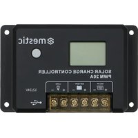
PWM MSC-2010 - Controller Mestic - Free user manual and instructions
Find the device manual for free PWM MSC-2010 Mestic in PDF.


User questions about PWM MSC-2010 Mestic
0 question about this device. Answer the ones you know or ask your own.
Ask a new question about this device
Download the instructions for your Controller in PDF format for free! Find your manual PWM MSC-2010 - Mestic and take your electronic device back in hand. On this page are published all the documents necessary for the use of your device. PWM MSC-2010 by Mestic.
USER MANUAL PWM MSC-2010 Mestic
natural_image
Technical line drawing of a device casing with mounting brackets and a control panel (no text or symbols)
natural_image
Top-down schematic of a device casing with control panel and vent (no text or symbols)Relax... it's mestic
User instructions EN
◆ Products adopt 32-bit high-speed main control chip and large-screen LCD, with adjustable charging and discharging parameters.
It supports such five battery types as custom, sealed lead-acid (factory default), gel lead-acid, flooded (opencell) lead-acid, lithium battery (default lithium iron phosphate).
◆ USB dual-port output is provided, and the maximum current can reach 2A, which supports high-current charging of iPhone, iPad, Android mobile phones, and other devices.
◆ Automatic identification of lead-acid battery 12V/24V system voltage.
The complete multi-stage PWM charging management can be set to off-load charging for better support of voltage-sensitive loads.
◆ Rich load working modes are easy to use in various DC loads.
◆ Protective functions including built-in reverse polarity protection, open circuit protection, high temperature protection, and overcurrent/short circuit protection(can be set) are self-recovery type without damage to the controller.
◆ Dual MOSanti-backflow circuit is equipped with ultra-low heat generation.
◆ Lithium battery activation function is provided.
◆ The user-friendly browsing design and dynamic interface are convenient and intuitive for operation.
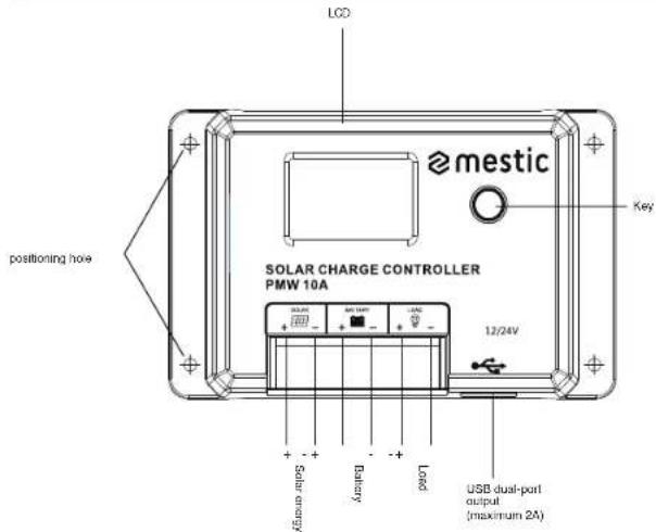
II. Panel Diagram
text_image
LCD mestic Positioning hole SOLAR CHARGE CONTROLLER PMW 10A 12/24V Solar energy Battery Load USB dual-port output (maximum 2A) KeyIII. Installation Instructions and Precautions
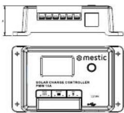
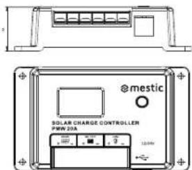
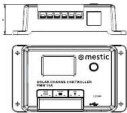
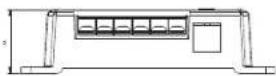
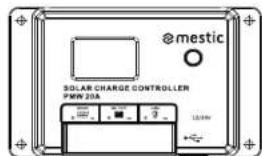
- The controller should be installed firmly, and the dimensions are as follows: MSC-2010 Overall dimension: 120*75*34mm Mounting dimension: 108.5*57.5mm MSC-2020 Overall dimension: 134*85*36mm Mounting dimension: 121*70mm
- Mounting hole diameter: 3.5mm
text_image
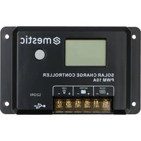
@mestic SOLAR CHARGE CONTROLLER PWR 10A 120kVMSC-2019
text_image
@mestic SOLAR CHARGE CONTROLLER PWM 20A 120kWMSC-2020
- Operation Instructions:
1). The first step is to connect the battery: If the connection is correct, the controller screen will light up, otherwise, please check whether the connection is correct and stable. 2). These second step is to connect the solar panel: If there is strong enough sunlight (the voltage of the panel is higher than the voltage of the battery), the sun icon on the LCD screen will light up, otherwise, please check whether the connection is correct and stable. 3). The third step is to connect the load: connect the load cable to the load output terminal of the controller, and the current should not exceed the rated current of the controller. 4. The controller will generate heat during operation, and it is recommended to install it in aventilated and heat-dissipating environment.
- Select cables with sufficient capacity to avoid excessive loss on the line and misjudgment by the controller.
6.A common positive electrode design is applied in the controller. If grounding is required, please ground the positive electrode.
-
It is important to fully charge the battery frequently. The interval should be at least once a month, otherwise, it will suffer permanent damage. The battery can only be fully charged when more energy enters the battery than used by the load. Users should keep this in mind when configuring the system.
-
Please check whether each wiring terminal of the controller is locked, otherwise, the terminal will be vulnerable when the current is excessive.
EN
IV. State icon
| LCD icon | Content | State |
 | Day or charging | Normal on |
| Night identification | OFF | |
 | No load | Arrow off |
| On load | Normal on | |
 | Battery status normal | Full on |
| Over-voltage | ||
 | Over-discharge | Full on |
V. LCD Schematic Diagram
text_image
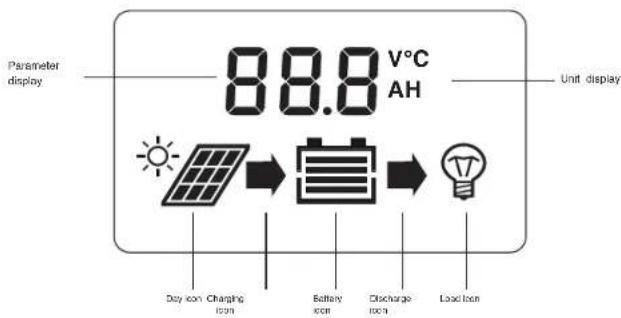
Parameter display 88.8 V°C AH Unit display Day icon Charging Icon Battery Icon Discharge Icon Load IconEN
VII. LCD Screen Browsing Menu
- Main page
Main page
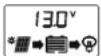
1.1 Click the key to turn the load on or off
Load on
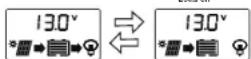
2. Menu Interface
Hold down the key for 2s to enter the parameter menu.
Short pressto switch the parameter menu (asshown in the figure below); hold down for 2sto enter the parameter setting page (parameter flashes, short pressto adjust the parameter, hold down for 2s to confirm the parameter, and exit the adjustment).
It will automatically exit the setting mode after 5s without button operation and enter the real-time data page. At the same time, after completing the last parameter setting, short press to return to the main page of real-time data.
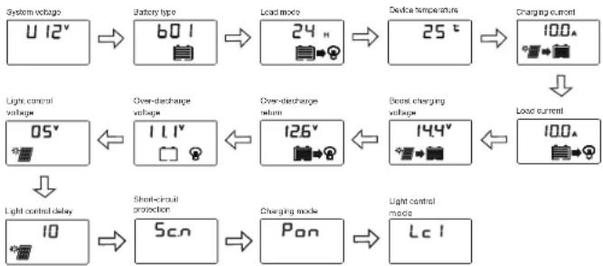
flowchart
graph TD
    A["12V battery type"] --> B["60V"]
    B --> C["24V"]
    C --> D["25°C"]
    D --> E["100A charging current"]
    E --> F["Load current"]
    G["05V light control voltage"] --> H["1.1V"]
    H --> I["126V"]
    I --> J["144V"]
    J --> K["100A"]
    L["10V light control delay"] --> M["50V"]
    M --> N["60V"]
    N --> O["70V"]
    O --> P["80V"]
    P --> Q["90V"]
    Q --> R["100V"]
    S["Short-circuit protection"] --> T["50V"]
    T --> U["60V"]
    U --> V["70V"]
    V --> W["80V"]
    W --> X["90V"]
    X --> Y["100V"]
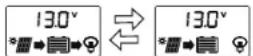
Note: The setting of boost charging voltage is applicable only in b04 and b07. When the battery voltage rises to thisset voltage, PWM charging will be started. During normal charging, the arrow remains lit, and after entering the float charging, the arrow turns to flash slowly. (It is recommended to keep the default value)
VIII. Controller Reboot and Factory Data Reset
- Hold down the key for more than 10s until F01 is displayed on the screen to restart the controller;
- Hold down the key for more than 20 seconds until the screen displays F02 to restore the factory default parameters.
IX. Battery Type Setting
On the main interface of real-time data, hold down the key for 2s to enter the parameter setting menu. Short press to switch to the "Battery Type" setting menu, hold down the key for 2s to enter the setting Interface, and the parameters will flash. Short press to adjust the parameters, hold down the key for 2s or keep 5s without key operation to confirm the parameters and exit the adjustment mode. See "Table E" for controller battery types.
Note: After changing the battery type and system voltage, the controller needsto be powered on again, otherwise it will operate according to the battery type and system voltage before setting.
Table EBattery type and display code table
| Character display code | Battery type | Remarks |
| b01 | Sealed lead-acid battery | Factory default |
| b02 | Gel lead-acid battery | |
| b03 | Flooded lead-acid battery | |
| b04 | Tornary lithium battery | |
| b07 | Lithium iron phosphate battery |
X. Load-related Parameter Settings
1. Load operating modes
1). Light control mode (00H): The load is turned on or off by the light control signal.
2). Time control mode (01H-23H): The load is turned on by the light control signal and turned off after a delay.
Lc1 means that the load works at night, Lc2 means that the load works during the day, and the light control has priority over the time control to turn off the load. Lc3 means that the load works at night, Lc4 means that the load works during the day, and the time control has priority over the light control to turn off the load. For example: if set to 16h, while the length of night/day is only 12h, then Lc1/2 will only operate for 12h, while Lc3/4 will operate the set value of 16h; the default is Lc1 state.
3). Normal on mode (24h): supply power to the load for 24 hours.
4). C2A mode: the load works for 2 hours a day, stops for 15 minutes, and keeps this mode
circulating.
5). C2d mode: the load works every 2 hours during the daytime, stops for 15 minutes, and keeps this mode circulating.
6). C2d mode: the load works every 2 hours at night, stops for 15 minutes, and keep this mode circulating.
(Note: No matter which load working mode is set, when the battery is discharged to the low voltage disconnect voltage, the controller will forcibly turn off the load. When the controller is active, the load will remain off)
| Display | Mode |
| 00H | Light control mode |
| 01H-23H | Time control mode |
| 24H | Normal on mode (factory default) |
| C2A | The load operates for 2 hours a day and stops for 15 minutes |
| C2d | The load operates for 2 hours in the daytime and stops for 15 minutes |
| C2n | The load operates for 2 hours at night and stops for 15 minutes |
2. Light control voltage
In the light or time control mode, when the controller detects that the photovoltaic panel (PV panel) voltage is less than this set value, it will turn on the load after a delay, otherwise, it will turn off the load. At night, if the ambient light around the solar panel is too bright which makes the output voltage of the solar panel become high, it will cause the controller to automatically turn off the load. It can be solved by adjusting this value.
Setting Recommendations: It is recommended to keep the default value.
3. Light control delay
When the controller detects that the voltage of the PV panel is lower than the set threshold, it will turn on the load after a delay. This time value can be used to prevent the light from being turned off because of misjudgment caused by car lights or lightning interference at night.
Setting Recommendations: It is recommended to keep the default value.
XI. Special Function Settings
-
Short-circuit protection setting: Sc.n means short-circuit protection on; Sc.F means short-circuit protection off, please turn off the short-circuit protection function for equipment with an excessive starting current. The default mode is on.
-
PWM charging setting (only applicable in b04, b07): Pon means PWM charging mode; PoF means disconnected charging mode, it is recommended to use disconnected charging mode for voltage-sensitive loads. The default mode is on.
XII. Error Code Table
| Display code | Related problem |
| E0 | No error |
| E1 | Battery over-discharge |
| E2 | Battery over-voltage |
| E4 | Load short-circuit |
| E5 | Load overload |
| E6 | Controller internal overtemperature |
| E10 | Solar panel overvoltage |
XIII. Common Problems and Solutions
| Phenomenon | Common problems and solutions |
| LCD screen does not light up | Please check whether the connection of battery is correct |
| LCD screen does not display completely or not update | Please check whether the connection of battery is correct |
| The battery panel icon does not light up with sunlight | Please check whether the connection of the photovoltaic cell is incorrect, and the contact isolable;whether the voltage of the battery board is less than the battery voltage |
| Others | Check whether the wiring is reliable and whether the system voltage identification is correct |
EN
| Model | MSC-2010 | MSC-2020 | |
| Rated current | Charge | 10A | 20A |
| Load | 10A | 20A | |
| Rated power | 12V/150W24V/300W | 12V/300W24V/800W | |
| System voltage | 12V/24V/0-(automotive identification) | ||
| No load less | <7mA/12V: <10mA/24V | ||
| Maximum PV input voltage | Start the protection and stop charging when the voltage is above 55V. Continue to charge when the voltage is below 50V. | ||
| Maximum allowable voltage at the battery end | <32V | ||
| Battery type | b01(SLD)x224V | b02(GEL)x224V | |
| Over-voltage protection | 18.0V | 18.0V | |
| Equalizing charging voltage | 14.6V | - | |
| Boost charging voltage | 14.4V | 14.2V | |
| Host charge voltage | 13.8V | 13.8V | |
| Charging reconnect voltage | 13.2V | 13.2V | |
| Over-discharge reconnect voltage | 12.6V | 12.6V | |
| Over-discharge voltage | 11.1V | 11.1V | |
| Equalizing charging time | 2H | - | |
| Boost charging time | 2H | ||
| Charging method | PWM charging is the default mode, and b04b07 can be set to pulse charging | ||
| USB output | 5V/2A | ||
| Operating temperature | -55°C to 60°C; | ||
| Altitude | ≤3000m | ||
| Protection grade | IP32 | ||
| Net weight | 130g 180g | ||
| Protection function | solar panel short-circuit protection, battery panel and battery reverse connection protection | ||
| Over-temperature protection, bad overload protection, and short-circuit protection | |||
| Product dimensions | 120°75'34 134'85'36 | ||
EN

mestic®
EN
Solar charge controller PWM MSC-2010/-2020
Made in P.R.C - Imported by
Protection of the environment
This symbol attached to the product means that it is an appliance whose disposal is subject to the directive on waste from electrical and electronic equipment (WEEE). This appliance may not in any way be treated as household waste and must be subject to a specific type of removal for this type of waste. Recycling and recovery systems are available in your area (waste removal) and by distributors. By taking your appliance at its end of life to a recycling facility, you will contribute to environmental conservation and prevent any harm to your health.

mestic
Solarladeregler PWM MSC-2010/-2020
natural_image
Top-down schematic of a device casing with control panel and vent (no text or symbols)Relax... it's mestic
User instructions EN
X. Load-related Parameter Settings
- Betriebsarten laden
natural_image
Top-down schematic of a device casing with control panel and vent (no text or symbols)Relax... it's mestic
User instructions EN
natural_image
Top-down schematic of a device casing with control panel and vent (no text or symbols)Relax... it's mestic'
User instructions EN
natural_image
Top-down schematic of a device casing with control panel and vent (no text or symbols)Relax... it's mestic
User instructions EN
Carlos on Carlos off
2. Interfaccia del menu
natural_image
Top-down schematic of a device casing with control panel and vent (no text or symbols)Relax... it's mestic
User instructions EN
Monleringsdimension: 108.5*57.5mm
Monteringsdimension: 121'70mm
text_image
@mestic SOLAR CHARGE CONTROLLER PWR TLE 100kV 120kVMSC-2019
text_image
@mestic SOLAR CHARGE CONTROLLER PWI 20A 12.0kWMSC-2020
natural_image
Top-down schematic of a device casing with control panel and vent (no text or symbols)Relax... it's mestic
User instructions EN
natural_image
Top-down schematic of a device casing with control panel and vent (no text or symbols)Relax... it's mestic
User instructions EN
Nonfirst leading for all present, 0_g either at our half e
XIII. Common Problems and Solutions
Euro Accessoires hereby declares that the MSC-2010/2020 device complies with the basic requirements and other relevant regulations listed in the European Electromagnetic Compatibility Directive (2014/30/EU) and the Low Voltage Directive (2014/35/EU). A full declaration of conformity can be requested from the address on the back cover.
DE