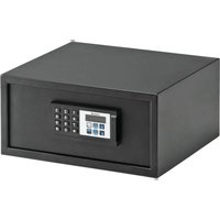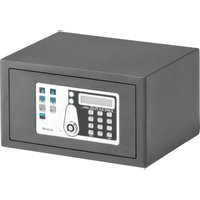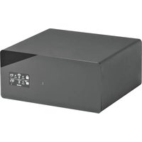
SAFE DRAWER - Safe Indel B - Free user manual and instructions
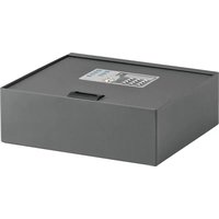
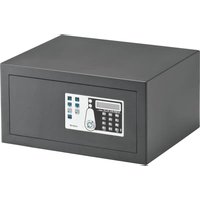
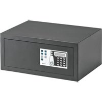
Find the device manual for free SAFE DRAWER Indel B in PDF.


User questions about SAFE DRAWER Indel B
0 question about this device. Answer the ones you know or ask your own.
Ask a new question about this device
Download the instructions for your Safe in PDF format for free! Find your manual SAFE DRAWER - Indel B and take your electronic device back in hand. On this page are published all the documents necessary for the use of your device. SAFE DRAWER by Indel B.
USER MANUAL SAFE DRAWER Indel B
USO DEL PALMARE (OPTIONAL)
text_image
DriverSetup The drive is successfully Pre-installed in advance! OKnatural_image
Product display of a digital payment terminal with control panel and accessories (no visible text or symbols)ITALIANO
MENU DEL PALMARE
5 SetLamp (Imposta luce)
text_image
Hotel Safe Device was found in com3 OKFigura 1 Figura 2
text_image
Hotel Safe Device was not found 3! OK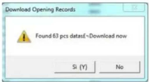
text_image
Download Opening Records Found 63 pcs datasE~Download now Si (Y) NoFigura 3 Figura 4
text_image
Operate Setting Query Read Open Print Preview Printer setup Save Save as Data File Exit ID Date Time Unlock Method 001 5/15/2015 15:59 admin 002 5/15/2015 15:58 client 003 5/15/2015 15:57 admin 004 5/15/2015 15:46 client 005 5/15/2015 15:45 admin 006 5/15/2015 15:44 client 007 5/15/2015 15:43 admin 008 5/15/2015 15:43 admin 009 5/15/2015 15:42 client 010 5/15/2015 15:34 client 011 5/15/2015 15:33 admin 012 5/15/2015 15:33 admin 013 8/6/2012 05:32 client 014 8/6/2012 05:14 client 015 8/2/2012 23:32 client 016 7/27/2012 00:06 client 017 7/7/2012 05:42 client 018 7/7/2012 05:41 client 019 7/1/2012 00:22 client 020 7/1/2012 00:20 admin 021 7/1/2012 00:06 client 022 7/1/2012 00:05 client F D E F G C l e a r W e l c o m e l E M E L 5/28/2015 2:50:50 PMFigura 5
ENGLISH

WARNING
This equipment is not intended for use by children or persons with impaired physical, sensory, or mental abilities, or without sufficient experience or expertise, unless they have benefited from supervision or instructions on how to use of the equipment provided by appointed safety managers. Children must be watched to ensure that they do not play with the equipment.
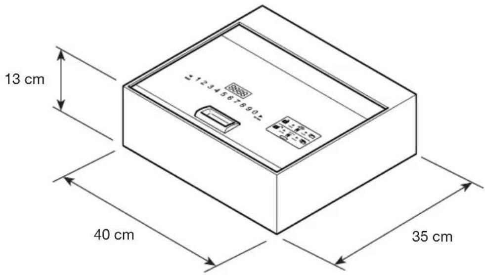
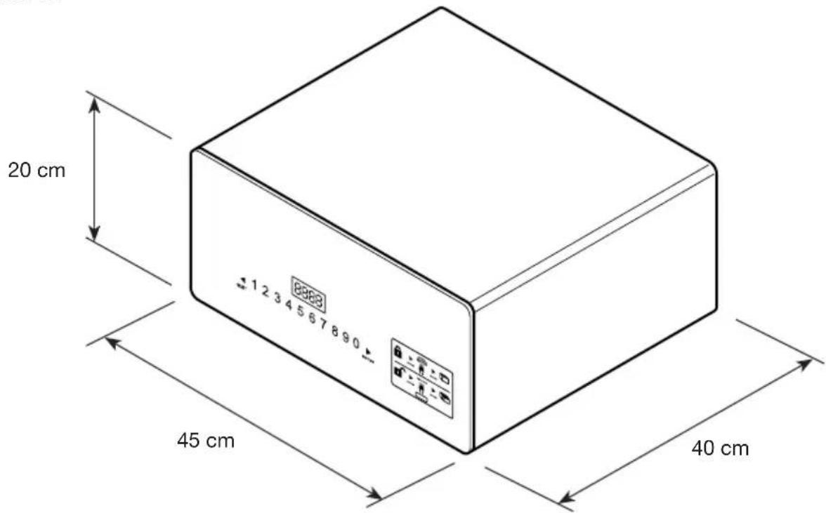
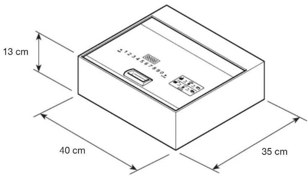
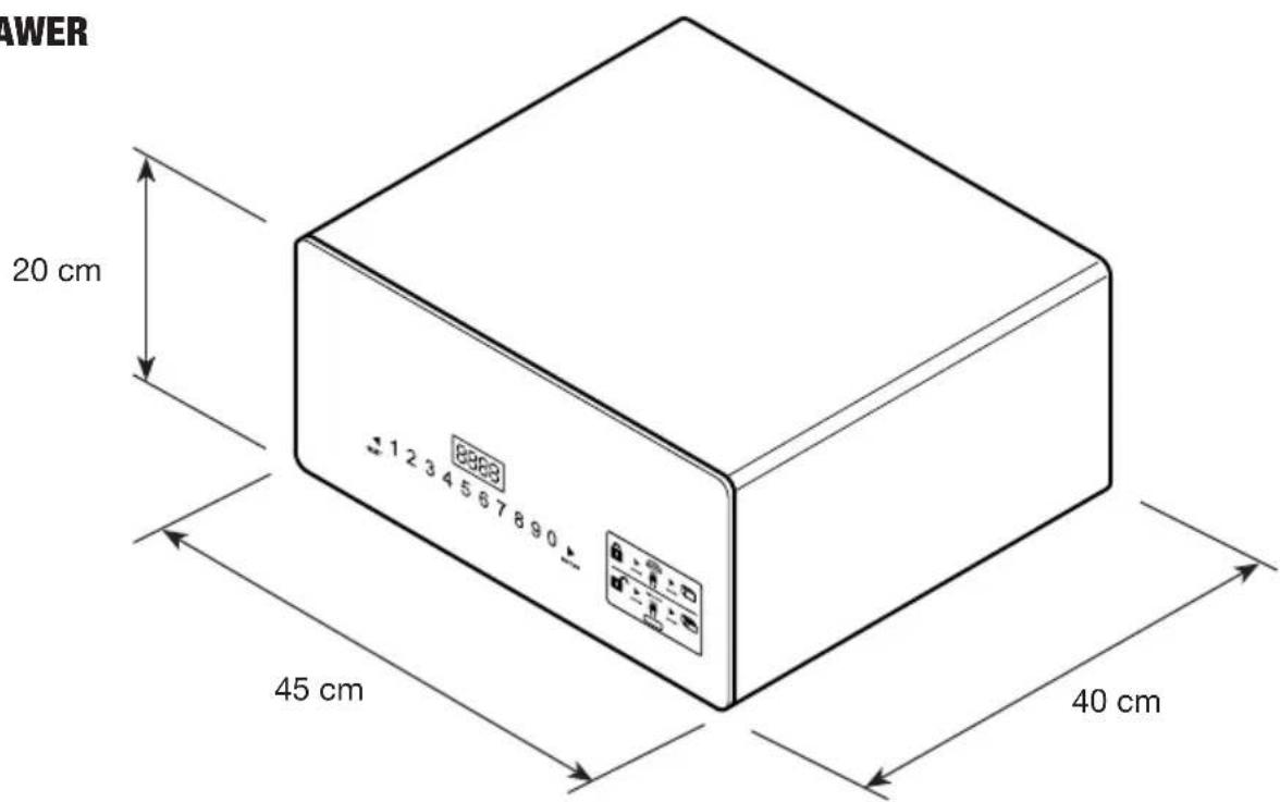
OVERALL DIMENSIONS
SAFE TOP OPEN
text_image
13 cm 40 cm 35 cmSAFE DRAWER
text_image
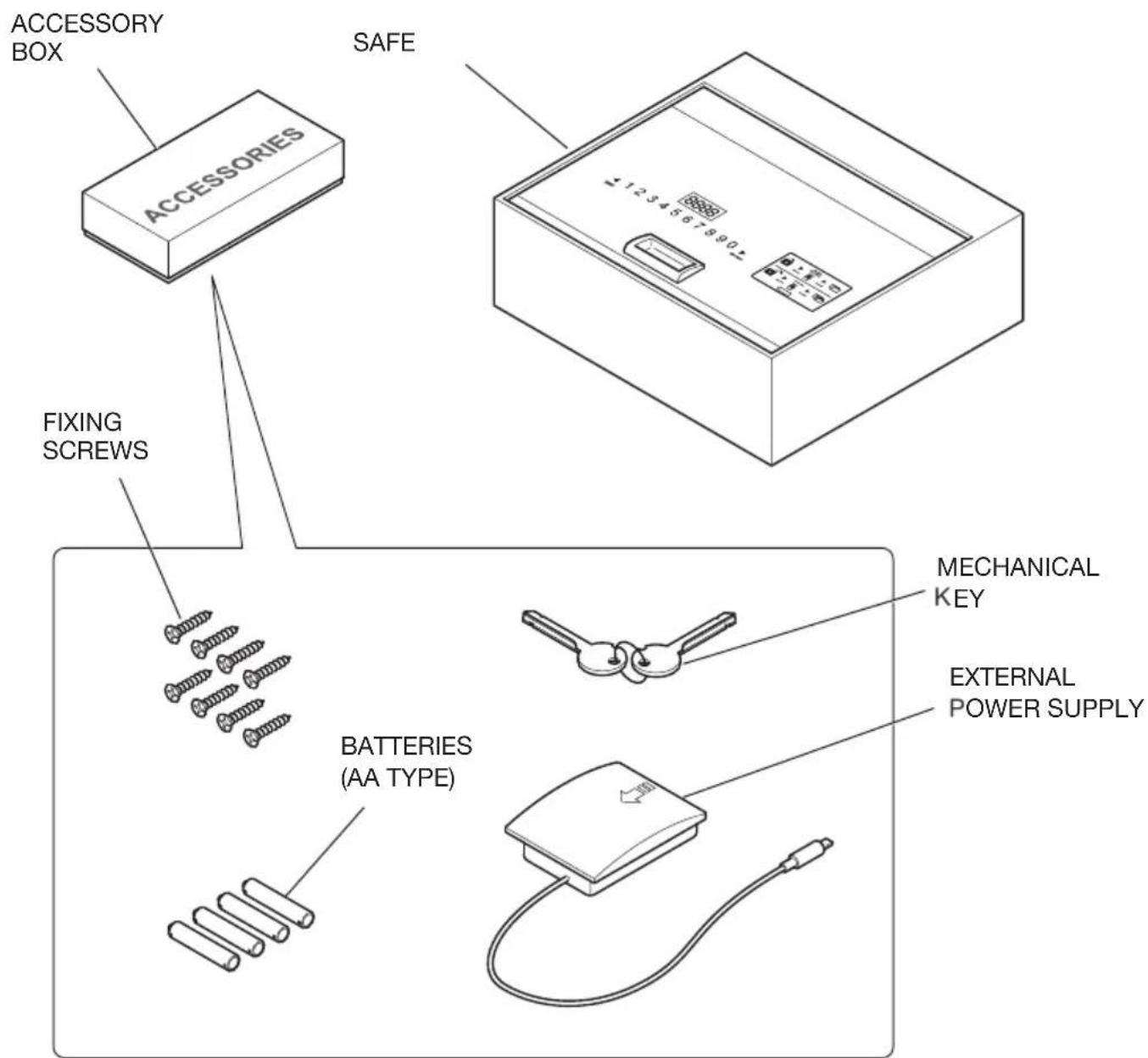
20 cm 45 cm 40 cmMATERIAL CONTAINED IN THE PACK - SAFE TOP OPEN
text_image
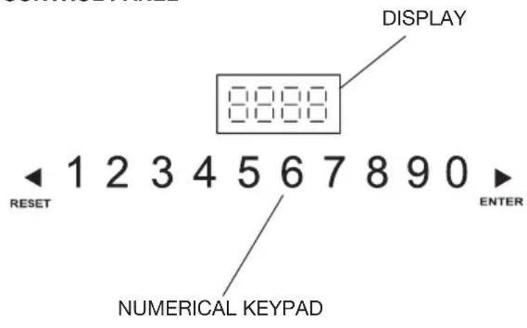
ACCESSORY BOX SAFE ACCESSORIES FIXING SCREWS BATTERIES (AA TYPE) MECHANICAL KEY EXTERNAL POWER SUPPLYCONTROL PANEL
text_image
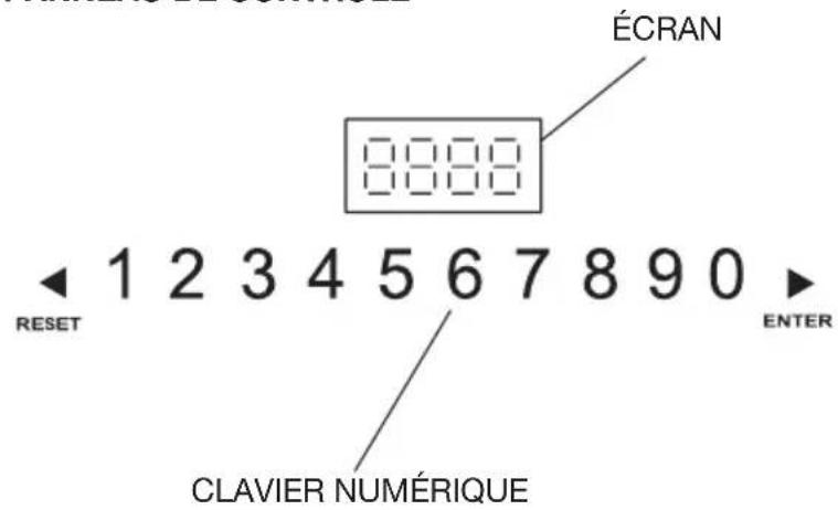
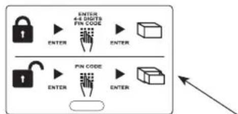
DISPLAY 8888 1 2 3 4 5 6 7 8 9 0 ▶ ENTER RESET NUMERICAL KEYPADINSTRUCTIONS LABEL FOR OPENING AND CLOSING

flowchart
graph TD
    A["LOCK"] --> B["ENTER"]
    B --> C["4-4 Digits PIN CODE"]
    C --> D["ENTER"]
    E["LOCK"] --> F["ENTER"]
    F --> G["FIN CODE"]
    G --> H["ENTER"]
    I["BOX"] --> J["BOX"]
EXTERNAL POWER SUPPLY SOCKET USB SLOT FOR DATA DOWNLOADING BELOW THE LABEL
ENGLISH
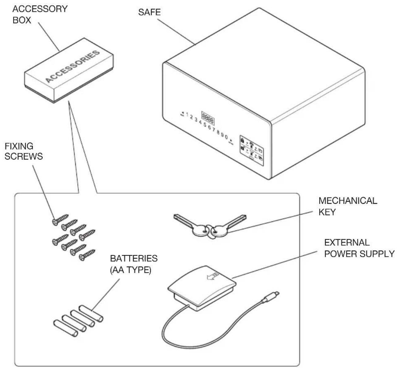
MATERIAL CONTAINED IN THE PACK - SAFE DRAWER
text_image
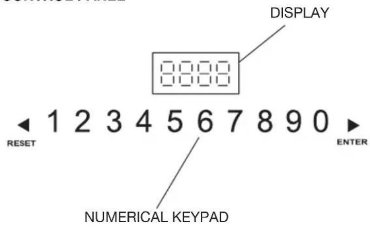
ACCESSORY BOX ACCESSORIES SAFE FIXING SCREWS BATTERIES (AA TYPE) MECHANICAL KEY EXTERNAL POWER SUPPLYCONTROL PANEL
text_image
DISPLAY 8888 1 2 3 4 5 6 7 8 9 0 ENTER RESET NUMERICAL KEYPADINSTRUCTIONS LABEL FOR OPENING AND CLOSING
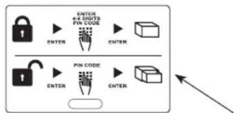
flowchart
graph TD
    A["Input"] --> B["4-4 GHz Pin Code"]
    B --> C["Output"]
    D["Input"] --> E["4-4 GHz Pin Code"]
    E --> F["Output"]
    G["Control"] --> H["Output"]
    I["Arrow Right"] --> J["Output"]
EXTERNAL POWER SUPPLY SOCKET USB SLOT FOR DATA DOWNLOADING BELOW THE LABEL
INSTALLATION
On receiving the Safe, the safe door will be OPEN.
The Safe must be installed by carrying out a few simple operations, in order to make it possible to use it.
POSITIONING
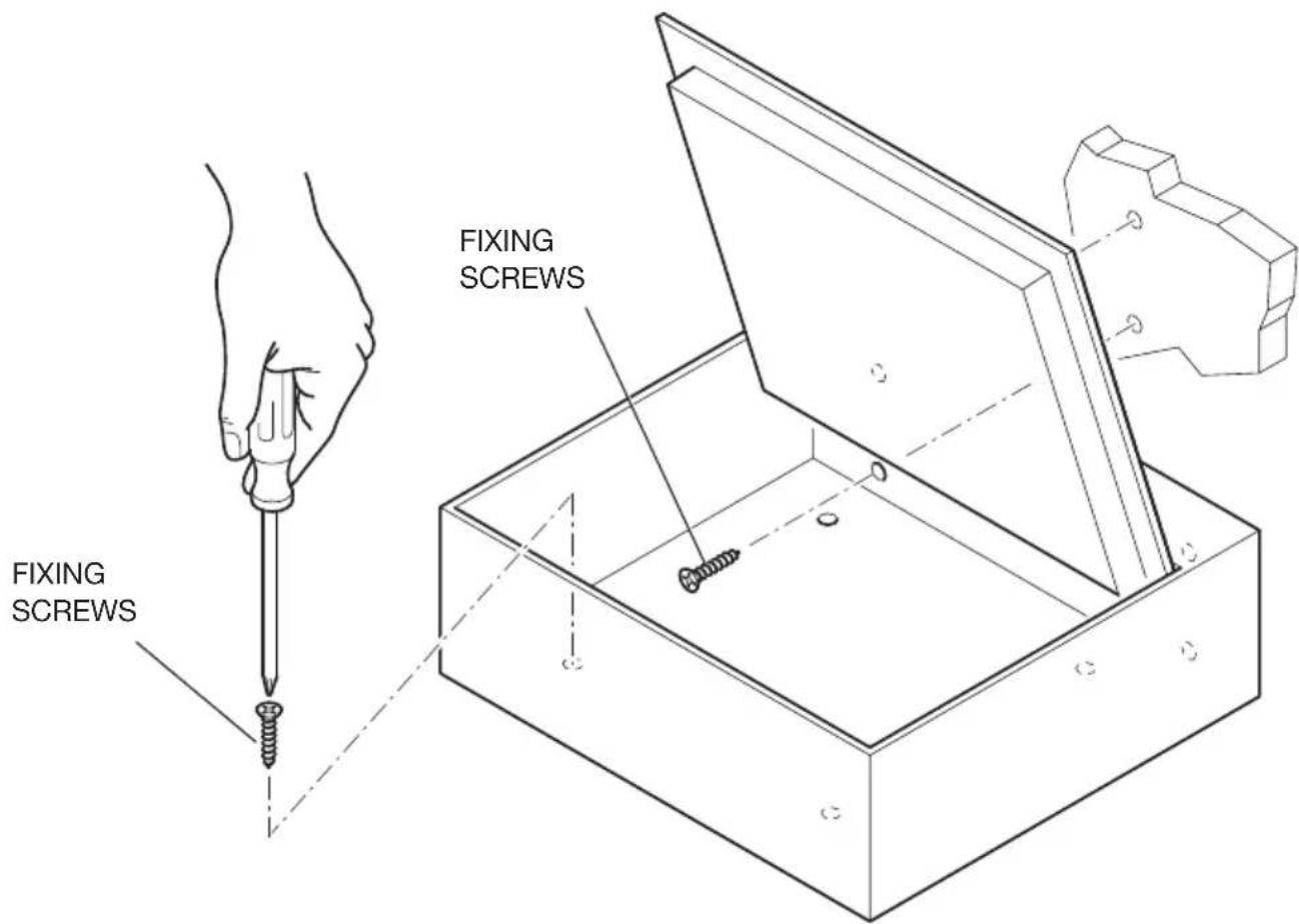
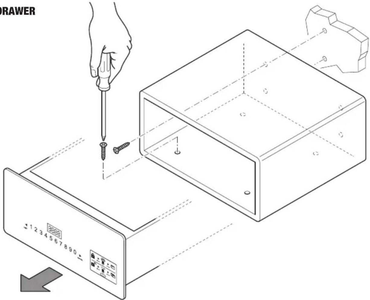
Position the Safe on a piece of furniture or inside a cabinet, securing it by means of the eight fixing screws provided.
The Safe is supplied with 8 fixing holes, 4 in the back panel and 4 in the horizontal panel, which the installer can use as required, according to the Safe installation setting.
To obtain access to the fixing holes of the SAFE Top Open, just open the door by pulling it upwards as shown in the figure, while to obtain access to the fixing holes of the SAFE Drawer, the drawer must be removed from its sliding guides, and then replaced after installation.
text_image
FIXING SCREWS FIXING SCREWSENGLISH
SAFE DRAWER
text_image
DRAWER 1234567890BATTERY INSERTION
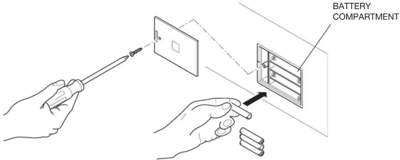
Before using the Safe, it is necessary to introduce the four supplied AA batteries in the special housing inside the drawer (Safe Drawer) or inside the compartment (Safe Top Open).
Check the correct polarity shown in the compartment.
text_image
BATTERY COMPARTMENT
WARNING
Batteries are delivered free of charge for the operating test and must be replaced in a short time.
INSTRUCTIONS FOR USE
1) Code setting: User code: 4-6 digits. Master code: 6 digits.
2) User code: factory set default code 1234; Master code: factory set default code: 848711.
3) After 3 failed attempts, the keypad will be locked for 15 min.
4) If the event logging function is used, the (Optional) handheld terminal unit can be used to read the latest 125 opening events data.
5) Internal light
OPENING THE SAFE
FIRST OPENING
Install 4 AA batteries in the internal battery compartment.
Press ▶ on the panel to activate the Safe; backlighting will be turned on and the digits will become clearly visible.
Key in the default code (factory-set code:1234) and ▶, if the code entry is correct, the panel will read "OPEN", and then "OPENED".
If the entered code is wrong, the panel will read 'E-CODE' followed by three short beep sounds.
CLOSING THE SAFE
Press the door to close it, press ▶ to activate the Safe, key in the code (4 to 6 digits), then press ▶ once again; the panel will read “CLOSE” and then “CLOSED” and the door will be automatically locked.
CHANGING CODES
CHANGING THE PERSONAL CODE
After opening the Safe, press ▶ then key in the new code (4 to 6 digits) and press ▶ once again to display "CLOSED". The new code will now be visible on the display unit - confirming that the operation has been successfully completed.
An (optional) Handheld unit is available to check the recorded events log or open the Safe in case of emergency: see the section on Handheld unit use.
CHANGING THE MASTER CODE

WARNING
We recommend changing the default Master Code as the same code is factory-set by the manufacturer for all its safes. Once you have changed the Master Code, make a note of the new Code and keep it in a safe place.
With the Safe door open, key in the original Master Code (6 digit code: 848711) and press the RESET key. The display will read NEW and you can then enter the new Master Code, also 6 digits-long.
Once you have entered the new Master Code, press the ▶ key again. The display will read AGAIN, now key in the new Master Code a second time and press ▶ again.
If the Master Code has been changed correctly, the display will read DONE.
RECOMMENDATIONS
After changing the code, do not immediately close the door. Carry out the following procedure at least 3 times to make sure that the code actually works.
Press ▶, backlighting will be turned on, key in the new code and press ▶, the Safe will beep twice to indicate correct code entry and “OPEN” will be displayed to indicate that the new code is working.
If the code is incorrect, the Safe will display "E-CODE" and beep 3 times. Carry out the "CODE SETTING" procedure again to change the code.
EMERGENCY OPENING
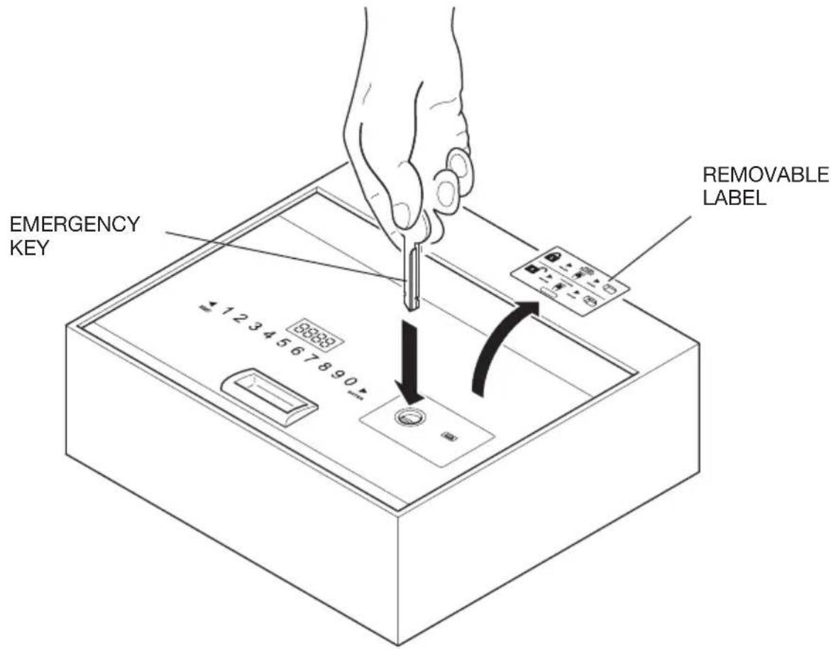
If you forget your personal code or cannot open the Safe for any other reason, the emergency key or the (optional) Handheld unit can be used to open the door.
ENGLISH
Emergency opening with key
1) Use the emergency key to open the Safe, keep the Safe door open and adjust the locking pins to their unlocked position. It will not be possible to remove the key;
2) Enter the code "1234" and press "ENTER" on the Safe; "close" will be displayed; however, the locking pins cannot be closed; at the same time, firmly turn the key until you hear the motor start. The Safe display will read "b-loc" and the locking pins will close.
The emergency key can now be removed.
3) Key in "1234" to open the locking pins and keep the safe open for the next guest.
"HIDDEN CODE" FUNCTION
Press ▶ to activate the Safe, then press the button ◀ twice and ▶ once, the device will beep twice. Access is obtained to the hidden code function. Repeat the procedure to reset the code.
text_image
EMERGENCY KEY REMOVABLE LABELKEYPAD LOCK
If an incorrect code is entered 3 times, the keypad will lock for 15 min. The safe will display "HOLD **", "***" indicates the time delay after which the keypad will be unlocked.
LIGHTING ACTIVATION AND DEACTIVATION
Activation: on opening the door, press the "RESET" key for 2 seconds to activate lighting. If the door is not closed, lighting will deactivate itself after 15 seconds. If the door is closed, lighting will deactivate itself automatically.
Deactivation: follow the same procedure described for activation.

WARNING
If the batteries run flat (voltage lower than 5 V), the display will read LO-BAT. If this happens replace the batteries as indicated in the BATTERY INSERTION paragraph.

WARNING
“◀” is also the delete key; press once to delete the latest entered key.
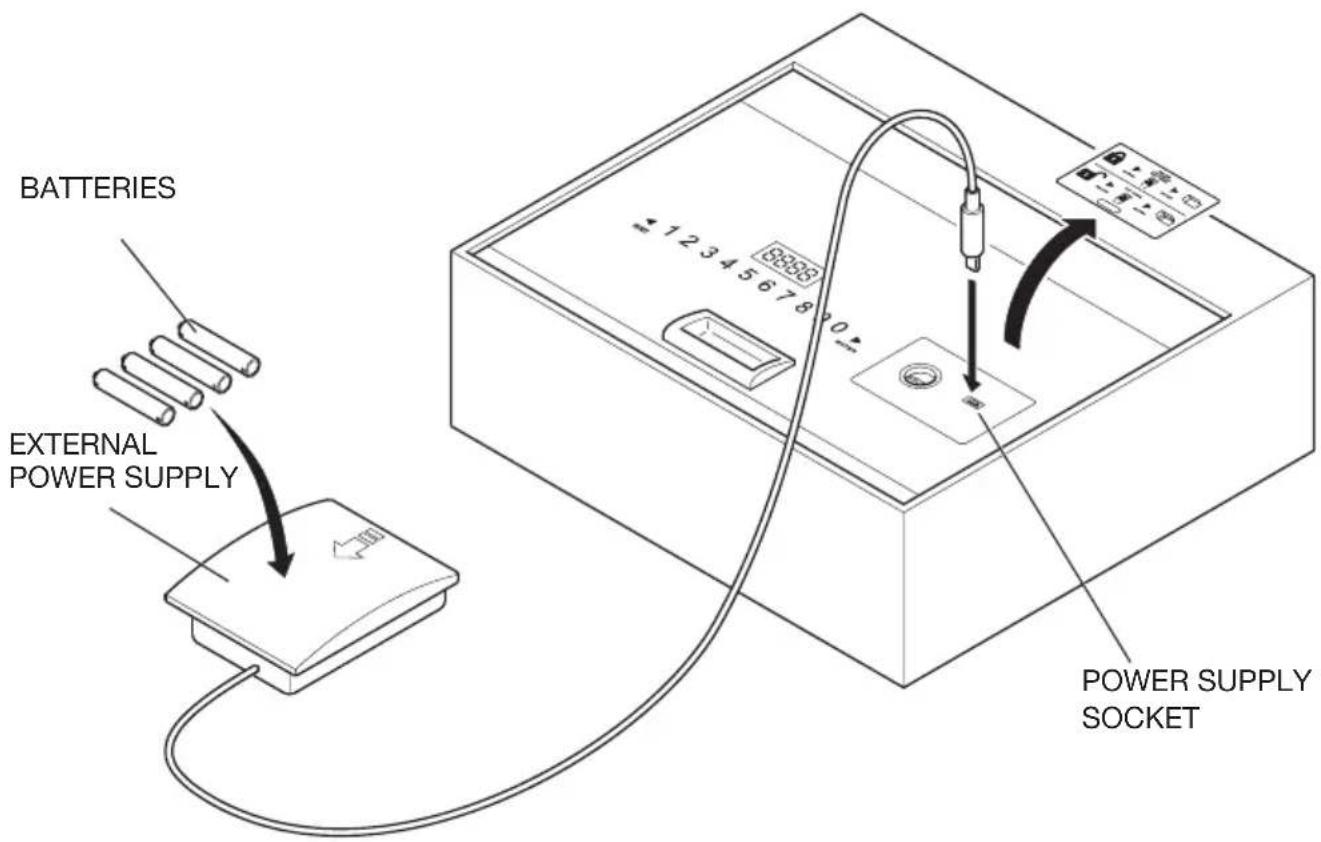
USE OF THE EXTERNAL POWER SUPPLY
If the batteries run flat while the Safe is closed, the Safe can be opened by using an external power supply. Enter the four supplied AA-type batteries, checking the polarity indication in the Power supply compartment, and plug the Power supply connector into the Safe socket shown in the figure.
Normal Safe operation will resume and it will now be possible to open the Safe to replace the internal batteries.
text_image
BATTERIES EXTERNAL POWER SUPPLY POWER SUPPLY SOCKETENGLISH
USE OF THE (OPTIONAL) HANDHELD DEVICE
SOFTWARE INSTALLATION
- Uncompress the .zip file into a folder; four files will appear as shown in figure 1. To install the driver, locate the "Driver.EXE" file and double-click it to start installation.
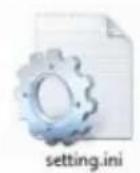



Figure 1 The four files displayed after uncompressing the .zip file.
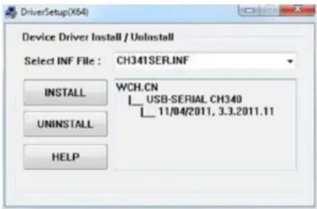
- Click on the first button to install the driver; after approximately 15 seconds "DriverSetup" will open, then click on the button outlined in red to confirm - as shown in the figure below. Installation is then completed and your Handheld unit can be connected to the computer via a USB connector.
text_image
DriverSetup(X64) Device Driver Install / Uninstall Select INF File : CH341SER.INF INSTALL UNINSTALL HELP WCH.CN USB-SERIAL CH340 11/04/2011, 3.3.2011.11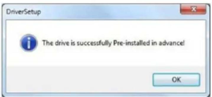
text_image
DriverSetup The drive is successfully Pre-installed in advance! OKHANDHELD UNIT POWER ON/OFF
Power on
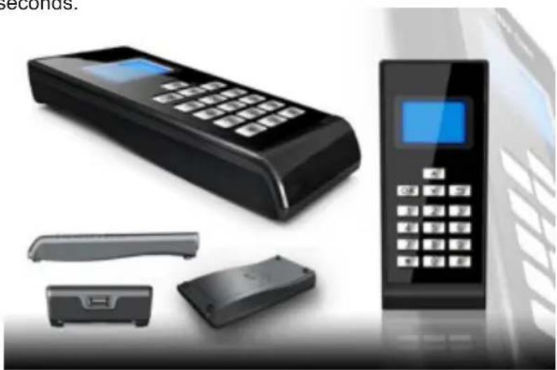
Insert 4 AAA batteries in the Handheld unit. After closing it back, press "5" for 2 seconds, the Handheld unit will start working.
Power off
To turn the Handheld unit off, press “” for 2 seconds.
natural_image
Product display of a digital payment terminal with control panel and accessories (no visible text or symbols)HANDHELD UNIT MENU
1 Records
1 ReadRecord
2 CheckRecord
3 DeleteRecord
2 Setclock
1 SetClock
2 SynClock (synchronise clock)
3 SetAdminiCode
1 ModifyCasePin
2 ModifyPalmarePin (modify handheld unit pin)
4 OpenSafe
5 SetLamp
6 PrintRecords
7 CommMode (communication mode)
1 IO-A √
2 IO-B
3 USART
4 PC
OPENING A RECORD
Connect the Handheld unit securely. When the Handheld unit starts working, press “▼” or “▲” to select “1. Records”, then press “OK” or “1” to access the submenu.
1 Press "RESET" on the keypad, then press "▼" or "▲" on the Handheld unit to select "1. ReadRecord", and press "OK" or "1" to read the record. If the operation is performed correctly, records can be read; otherwise, the screen will read "Failure".
2 Press “▼” or “▲” to select “2.CheckRecord”, then press “OK” or “2” to check the record. Press “▼” or “▲” to read the next or the previous record, then press “ ” to return to the previous menu.
3 Press “▼” or “▲” to select “3.DeleteRecord”, press “OK” or “3” to delete the current record.
4 From the "Records" menu, press " " to return to the main menu.
ENGLISH
CLOCK SETTING
Note: it is very important to set the clock on the Handheld unit and sync its time setting with the Safe's when this is installed in guest rooms. Otherwise, the event log read by the Handheld unit will refer to the factory-set time which will be incorrect. When the Safe batteries are changed, the time should be set and synced, too, otherwise event logging will stop at the time of battery charge end.
Connect the Handheld unit to the Safe.
Start the Handheld unit.
Press “▼” or “▲” to select “2. Setclock”, then press “OK” or “2” to access the submenu.
1 Press “▼” or “▲” to select “1. SetClock”, then press “OK” or “1” to set the time.
A Enter a figure to set the time
B Press "OK" to save your entry and return to the main menu
C Press “ ” to return to the main menu without saving your entry
2 Press “▼” or “▲” to select “2. SynClock”, then press “OK” or “2” to sync the time settings between the Handheld unit and the Safe.
A Press “OK” to sync the time on the Safe and the time on the Handheld unit. Upon setting completion, if the operation was successfully completed, the screen will read “Success”, otherwise, it will read “Failure”.
B Press “ ” to return to the main menu.
3 Press " ” to return to the main menu.
ADMINISTRATOR CODE SETTING
We advise not to change the administrator code unless this is necessary. As the code enables the Handheld unit and Safe to dialogue, if the Safe code is changed the Handheld unit code must be changed accordingly, too. Otherwise, the Handheld unit will be unable to read records from the Safe. When the administrator code is changed, make a note of it and keep it in a safe place.
1 Press “▼” or “▲” to select “SetAdminiCode”, then press “OK” or “3” to access the submenu.
Select "1. ModifyCasePin" and press "OK" or "1" to change the case pin. Enter a 6 digit code and press "OK". The code must be entered again. Enter it once again. "Success" or "Failure" will be displayed.
Note: If the administrator code on the Handheld unit or Safe is changed before carrying out the previous step, the administrator code will not be changed correctly. Identical codes must be used both for the Handheld unit and for the Safe. Otherwise, the two units will be unable to dialogue.
2 Press “▼” or “▲” to select “2. ModifyCeuPin” and press “OK” or “2” to change the Handheld unit pin. Enter a 6 digit code and press “OK”. Check that the Handheld unit pin and the case pin are identical.
SAFE OPENING
Select "Open Safe" and press "OK" or "4"; the Safe will open automatically.
LAMP SETTING
Select "SetLamp" then press "OK" or "5" to set the lighting.
Note: every time you change the light setting on a Safe, you will switch it from on to off. There are two setting positions: on and off. When it is on, the LED will light up automatically on opening the door; when it is off, it will not light up automatically.
RECORD PRINTING
Select "PrintRecords" and press "OK" or "6". It will now be possible to print the record.
Note: this printing function is only supported in the communication mode V1.0.
COMMUNICATION MODES
Three communication modes are available: IO-A, IO-B, USART and PC.
Note:
1 If the Handheld unit is used to power the Safe, start the Handheld unit first, then connect it to the Safe.
2 IO-A is a communication mode for first-generation Safes.
3 IO-B is a communication mode for second-generation Safes.
4 The PC mode allows the Handheld unit to be connected to the computer. At the same time, install the corresponding driver software in the computer; the Handheld unit can be used to communicate with the computer. Via the computer, it can be used to read and print records.
Before use, correctly set the communication mode, or the Handheld unit will be unable to dialogue with the Safe or the computer.
CONNECTION TO THE SAFE
1 Start the Handheld unit and set the communication mode "IO-A" to "IO-B".
2 Connect the Handheld unit to the Safe.
If the Safe is a first-generation device, the Handheld unit can be used as soon as it is connected. If the Safe is a second-generation device, press “*” to activate the Handheld unit then use the Handheld unit.
Note: if you are going through the required steps but malfunctioning is observed, the Safe may be a second-generation device; try pressing “*” to activate the Safe and repeat the operation.
ENGLISH
CONNECTION TO THE COMPUTER:
1 Start the Handheld unit and select the communication mode "PC".
2 Connect the Handheld unit to the computer; after USB recognition, the computer will automatically download some information from the Handheld unit. Double click on the file "HotelSafe.exe".
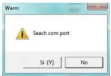
3 The computer will display "Search com port". Click on "Y". See figure 1 here below
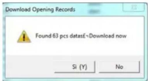
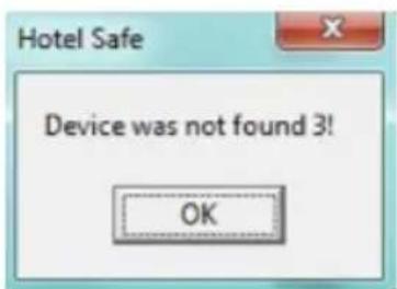
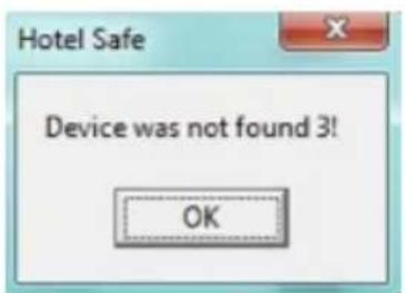
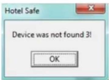
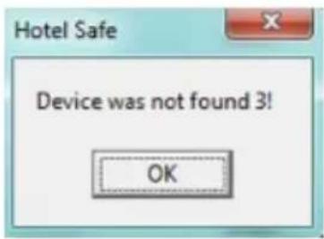
4 After 2 seconds the Handheld unit search will start and the message "Device was found in com" will be displayed, see figure 2. If the computer fails to recognise the USB, the message "Device was not found" will be displayed; see figure 3. This may happen if the driver.exe has not been installed.
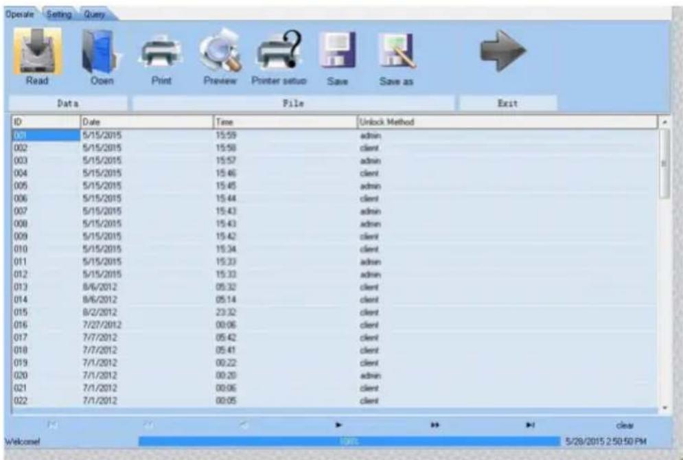
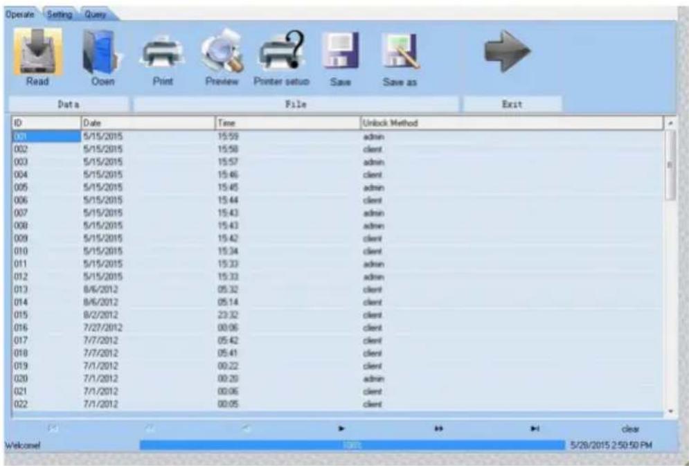
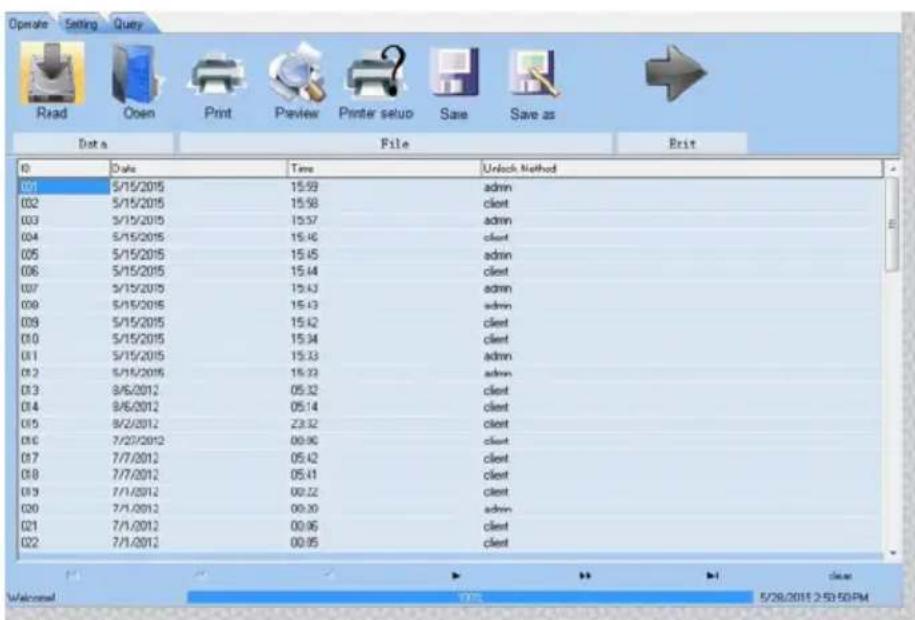
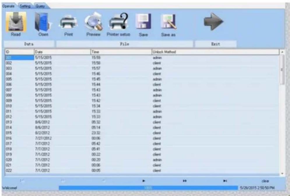
5 Then "Found pcs data, Download now" will be displayed, see Figures 4 - 6. Click on "Y" to read open records. The results are shown in Figure 5.
text_image
Warm Seach com port Si (Y) No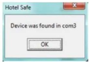
text_image
Hotel Safe Device was found in com3 OKFigure 1 Figure 2
text_image
Hotel Safe Device was not found 3! OK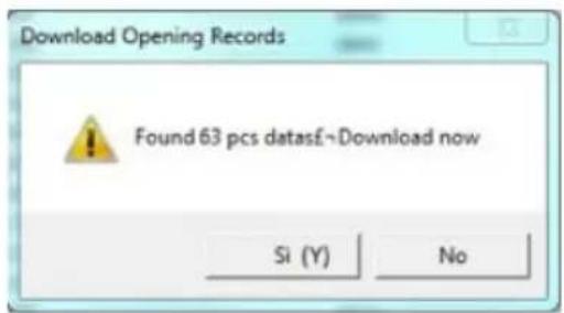
text_image
Download Opening Records Found 63 pcs datasE~Download now Si (Y) NoFigure 3 Figure 4
text_image
Operate Setting Query Read Open Print Preview Printer setup Save Save as Data File Exit ID Date Time Unlock Method 01 5/15/2015 15:59 admin 002 5/15/2015 15:58 client 003 5/15/2015 15:57 admin 004 5/15/2015 15:46 client 005 5/15/2015 15:45 admin 006 5/15/2015 15:44 client 007 5/15/2015 15:43 admin 008 5/15/2015 15:43 admin 009 5/15/2015 15:42 client 010 5/15/2015 15:34 client 011 5/15/2015 15:33 admin 012 5/15/2015 15:33 admin 013 8/6/2012 05:32 client 014 8/6/2012 05:14 client 015 8/2/2012 23:32 client 016 7/27/2012 00:06 client 017 7/7/2012 05:42 client 018 7/7/2012 05:41 client 019 7/1/2012 00:22 client 020 7/1/2012 00:20 admin 021 7/1/2012 00:06 client 022 7/1/2012 00:05 client Welcome! IRR 5/28/2015 2:50:50 PMFigure 5

ADVERTENCIA
text_image
DriverSetup The drive is successfully Pre-installed in advance! OKtext_image
Hotel Safe Device was found in com3 OKFigura 1 Figura 2
text_image
Hotel Safe Device was not found 3! OK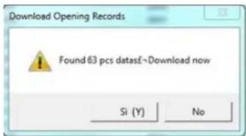
text_image
Download Opening Records Found 63 pcs datasE→Download now Si (Y) NoFigura 3 Figura 4
text_image
Operate Setting Query Read Open Print Preview Printer setup Save Save as Data File Edit ID Date Time Unlock Method 01 5/15/2015 15:59 admin 02 5/15/2015 15:58 client 03 5/15/2015 15:57 admin 04 5/15/2015 15:46 client 05 5/15/2015 15:45 admin 06 5/15/2015 15:44 client 07 5/15/2015 15:43 admin 08 5/15/2015 15:43 admin 09 5/15/2015 15:42 client 010 5/15/2015 15:34 client 011 5/15/2015 15:33 admin 012 5/15/2015 15:32 admin 013 8/6/2012 05:32 client 014 8/6/2012 05:14 client 015 8/2/2012 23:32 client 016 7/27/2012 09:06 client 017 7/7/2012 05:42 client 018 7/7/2012 05:41 client 019 7/1/2012 00:22 client 020 7/1/2012 00:20 admin 021 7/1/2012 00:06 client 022 7/1/2012 00:05 clientFigura
FRANÇAIS

AVERTISSEMENT
DIMENSIONS HORS TOUT
SAFE TOP OPEN
text_image
13 cm 40 cm 35 cmSAFE DRAWER
text_image
AWER 20 cm 8363 1 2 3 4 5 6 7 8 9 0 45 cm 40 cmCONTENU DE L'EMBALLAGE - SAFE TOP OPEN
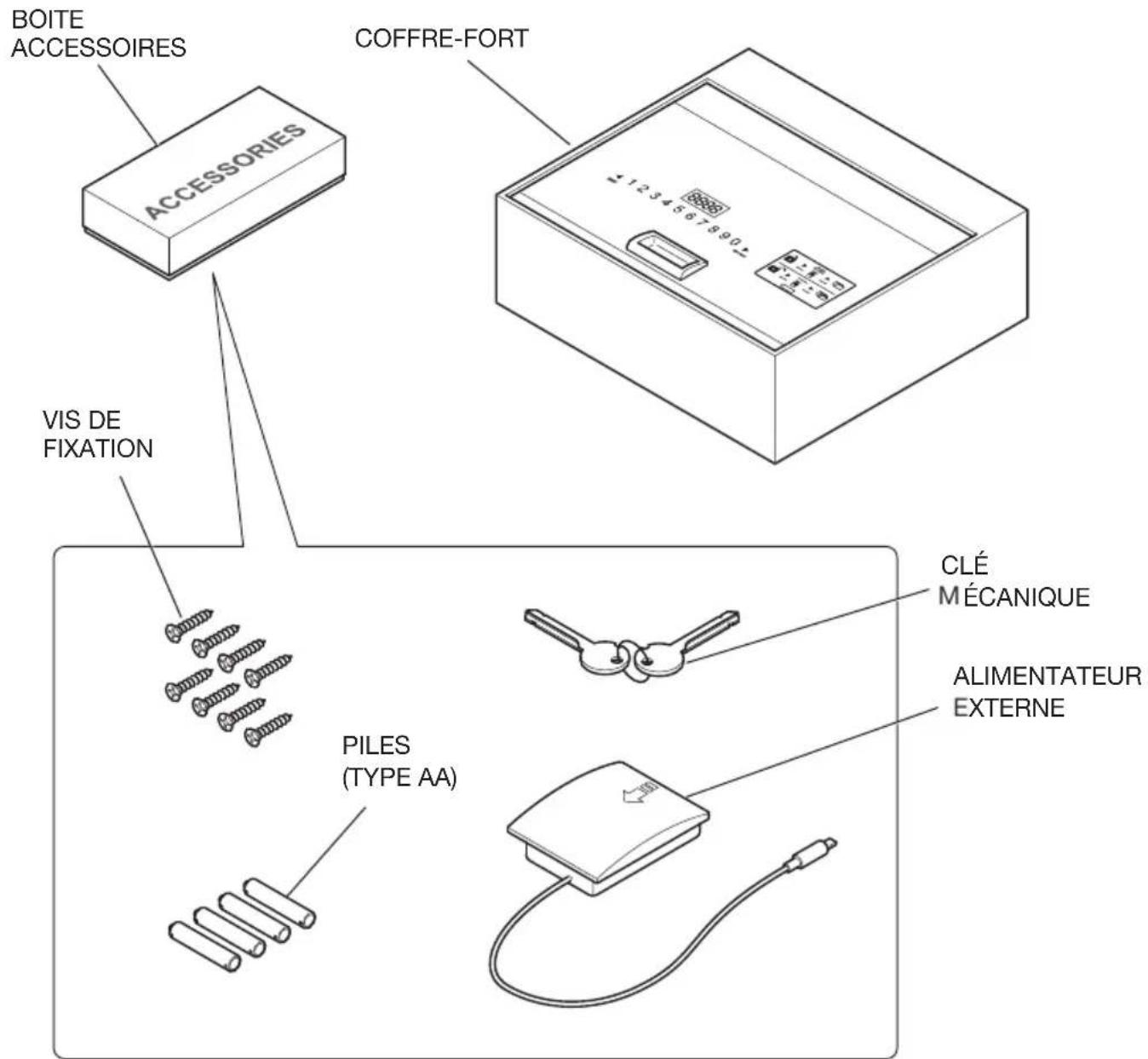
text_image
BOITE ACCESSOIRES COFFRE-FORT ACCESSORIES VIS DE FIXATION PILES (TYPE AA) CLÉ MÉCANIQUE ALIMENTATEUR EXTERNEPANNEAU DE CONTRÔLE
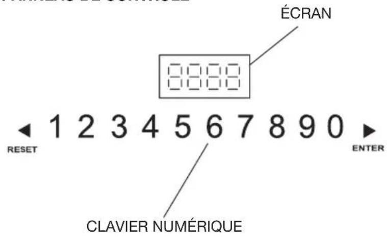
text_image
ÉCRAN 8888 1 2 3 4 5 6 7 8 9 0 ENTER RESET CLAVIER NUMÉRIQUEÉTIQUETTE INSTRUCTIONS
D'OUVERTURE ET FERMETURE
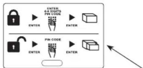
flowchart
graph TD
    A["Input"] --> B["4-4 Digits Pin Code"]
    B --> C["Enable"]
    D["Input"] --> E["4-4 Digits Pin Code"]
    E --> F["Enable"]
    G["Enable"] --> H["4-4 Digits Pin Code"]
    H --> I["Enable"]
    J["Enable"] --> K["4-4 Digits Pin Code"]
    K --> L["Enable"]
PRISE D'ALIMENTATION EXTERNE PRISE USB DE DÉCHARGEMENT DONNÉES SOUS L'ÉTIQUETTE
FRANÇAIS
CONTENU DE L'EMBALLAGE - SAFE DRAWER
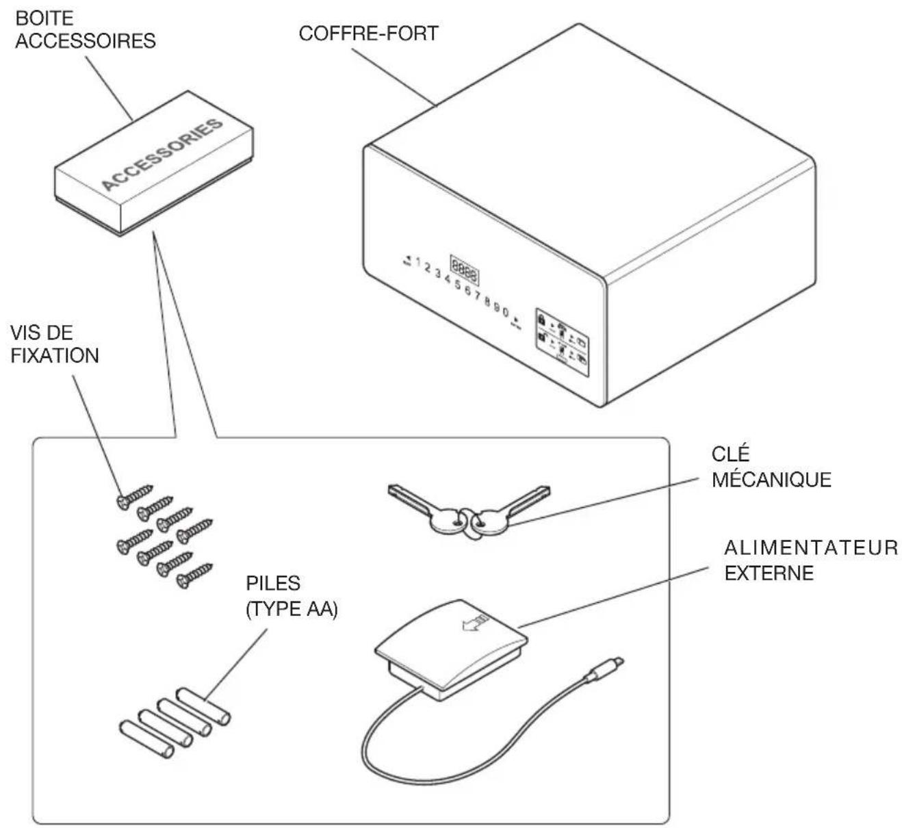
text_image
BOITE ACCESSOIRES ACCESSORIES COFFRE-FORT VIS DE FIXATION PILES (TYPE AA) CLÉ MÉCANIQUE ALIMENTATEUR EXTERNEPANNEAU DE CONTRÔLE
text_image
ÉCRAN 8888 1 2 3 4 5 6 7 8 9 0 ENTER RESET CLAVIER NUMÉRIQUEÉTIQUETTE INSTRUCTIONS
D'OUVERTURE ET FERMETURE
flowchart
graph TD
    A["Input"] --> B["4-4 Digits PIN CODE"]
    B --> C["Enable Button"]
    C --> D["Output"]
    E["Enable"] --> F["4-4 Digits PIN CODE"]
    F --> G["Enable Button"]
    G --> H["Output"]
PRISE D'ALIMENTATION EXTERNE PRISE USB DE DÉCHARGEMENT DONNÉES SOUS L'ÉTIQUETTE
INSTALLATION
text_image
LOGEMENT PILES
AVERTISSEMENT
text_image
DriverSetup The drive is successfully Pre-installed in advance! OKALLUMAGE ET EXTINCTION DE LA COMMANDE PORTABLE
Allumage
text_image
Hotel Safe Device was found in com3 OKFigure 1 Figure 2
text_image
Hotel Safe Device was not found 3! OK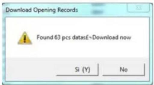
text_image
Download Opening Records Found 63 pcs datasE~Download now Si (Y) NoFigure 3 Figure 4
text_image
Operate Setting Query Read Open Print Preview Printer setup Save Save as Data File Exit ID Date Time Unlock Method 001 5/15/2015 15:59 admin 002 5/15/2015 15:58 client 003 5/15/2015 15:57 admin 004 5/15/2015 15:46 client 005 5/15/2015 15:45 admin 006 5/15/2015 15:44 client 007 5/15/2015 15:43 admin 008 5/15/2015 15:43 admin 009 5/15/2015 15:42 client 010 5/15/2015 15:34 client 011 5/15/2015 15:33 admin 012 5/15/2015 15:33 admin 013 8/6/2012 05:32 client 014 8/6/2012 05:14 client 015 8/2/2012 23:32 client 016 7/27/2012 90:06 client 017 7/7/2012 05:42 client 018 7/7/2012 05:41 client 019 7/1/2012 00:22 client 020 7/1/2012 00:20 admin 021 7/1/2012 00:06 client 022 7/1/2012 00:05 client Welcome: 1996 5/28/2015 2:50:50 PMFigure 5

HINWEIS
text_image
DriverSetup The drive is successfully Pre-installed in advance! OKtext_image
Hotel Safe Device was found in com3 OKtext_image
Hotel Safe Device was not found 3! OK