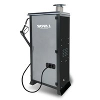
HHPV - Pressure washer Lavor - Free user manual and instructions
Find the device manual for free HHPV Lavor in PDF.


| Product type | Hot water high-pressure cleaner |
| Brand | Lavor |
| Model | HHPV |
| Power supply | 230-240 V single-phase or 400-415 V three-phase (depending on version) |
| Frequency | 50/60 Hz |
| Maximum water inlet pressure | 1 MPa (10 bar) |
| Maximum water inlet temperature | 40 °C |
| Minimum required water flow | 30 L/min |
| Outlet water temperature | Adjustable via thermostat |
| Fuel type | Diesel (gas oil) |
| Diesel tank capacity | Not specified |
| Detergent tank capacity | Not specified |
| Automatic shut-off system | Total Stop 24V (if included): engine stop after 15 s, complete shutdown after 20 min |
| Electrical protection | Thermal circuit breaker (single-phase) / magnetothermal switch (three-phase) |
| Gun safety device | Safety lock against accidental opening |
| Water inlet filter | Integrated filter to be cleaned periodically |
| Pump oil type | SAE 20/30 |
| Pump oil capacity | 0.7 kg |
| Usage | Professional, outdoor only |
| Accessories included | Gun, lance, nozzle, high-pressure hose |
| Main functions | High-pressure washing, hot water, detergent injection |
| Maintenance | Pump oil change (50h then 500h), water filter cleaning, boiler descaling |
| Safety | Total stop, gun safety lock, electrical overload protection |
| Warranty | 12 months minimum (depending on conditions) |
Frequently Asked Questions - HHPV Lavor
User questions about HHPV Lavor
0 question about this device. Answer the ones you know or ask your own.
Ask a new question about this device
Download the instructions for your Pressure washer in PDF format for free! Find your manual HHPV - Lavor and take your electronic device back in hand. On this page are published all the documents necessary for the use of your device. HHPV by Lavor.
USER MANUAL HHPV Lavor
natural_image
Exterior view of a black industrial enclosure with open door and internal compartments (no visible text or symbols)HHPV HHPX
2 Water temperature regulator
3 Internal switch
4 Burner switch
5 Detergent switch
6 High pressure water outlet
7 Water inlet + filter
8 Gun
9 Lance
10 High pressure hose
11 Rubber hose fitting
12 Nozzle
13 Detergent tank
14 Diesel tank
15 Control pilot lights (see control components)
16 Boiler rain guard
17 Pressure gauge
(FR)
natural_image
Close-up of a metallic mechanical component with a bolt and water droplets, labeled 'Fig. 2' (no readable text or symbols on the main subject)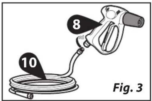
natural_image
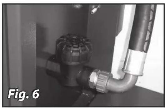
Close-up of a pipe fitting with a knob and fittings, labeled 'Fig. 6' (no other text or symbols visible)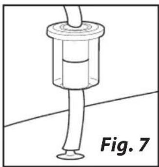
natural_image
Simple line drawing of a mechanical component with a cylindrical base and a cylindrical top, labeled 'Fig. 7' (no text or symbols on the diagram itself)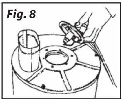
natural_image
Technical line drawing of a mechanical component with a hand holding a tool, labeled 'Fig. 8' (no text or symbols on the diagram itself)
natural_image
Line drawing of a mechanical device with a hand operating a wheel and a cup on the base (no text or symbols)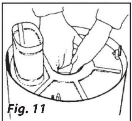
natural_image
Illustration of a hand pressing down on a cylindrical object on a circular base, labeled 'Fig. 11' (no text or symbols on the diagram itself)
natural_image
Simple line drawing of a rectangular object with two curved ends, labeled 'Fig. 12' (no text or symbols on the diagram itself)
natural_image
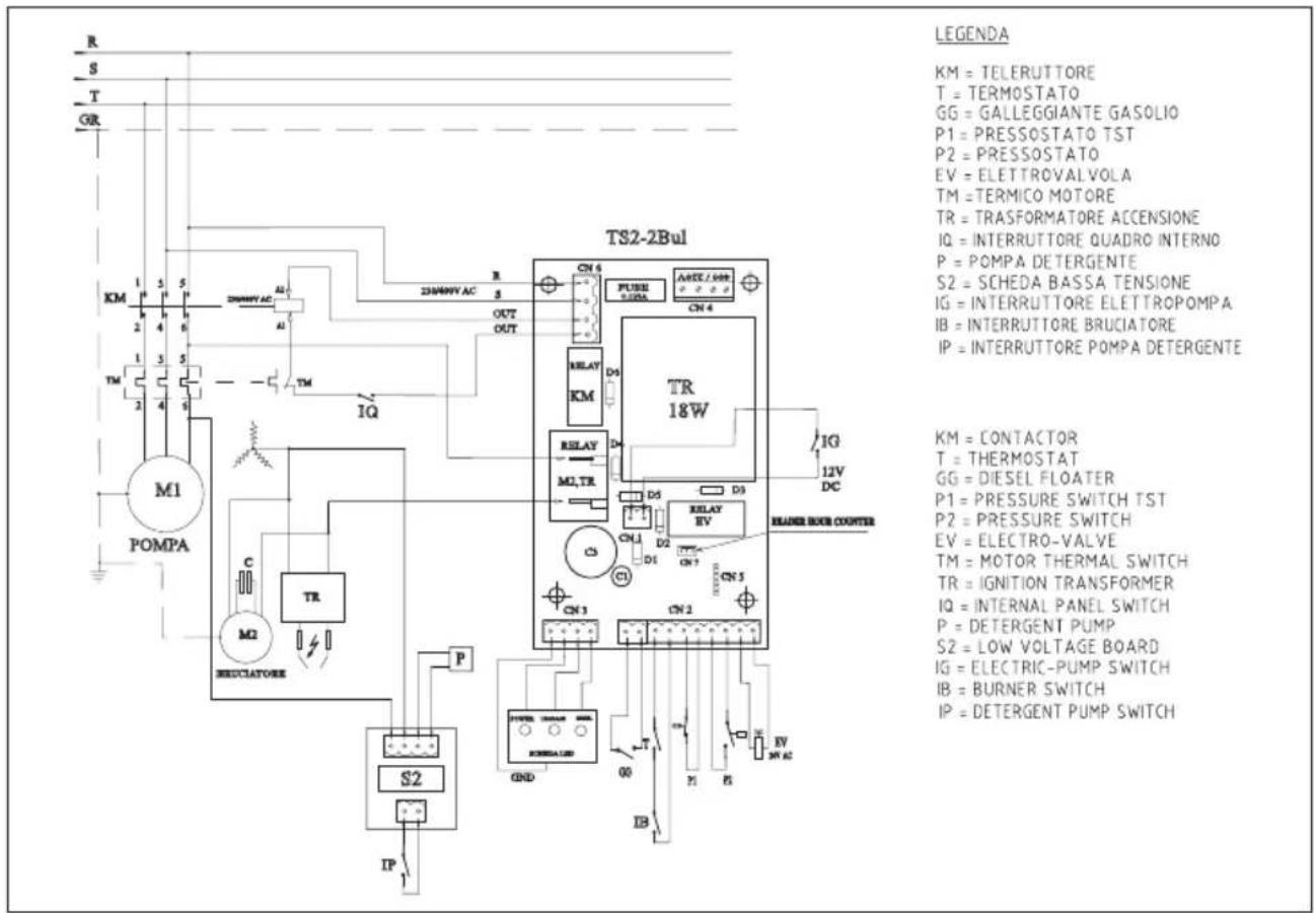
Illustration of hands pouring liquid from a pipe into a container (no text or symbols)> SCHEMA ELETTRICO • ELECTRIC DIAGRAM • SCHEMA ELECTRIQUE • ELEKTROSCHEMA • ESQUEMA ELÉCTRICO • ELEKTRICITEITSSCHEMA • HΛEKTPIKO ΔIΑΓΡΑΜΜΑ
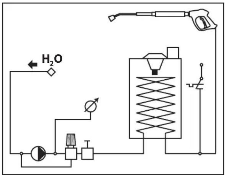
> SCHEMA IDRICO • WATER DIAGRAM • SCHEMA HYDRAULIQUE • WASSERUMLAUFSCHEMA • ESQUEMA HÍDRICO • WATERCHEMA • ΣΧΕΔΙΟ ΥΔΡΕΥΣΗΣ
flowchart
graph TD
    A["Hydraulic Pump"] --> B["Valve"]
    B --> C["Pressure Relief Valve"]
    C --> D["Pressure Gauge"]
    D --> E["Return Line"]
    F["H2O Input"] --> G["Flow Path"]
    G --> A
    style A fill:#f9f,stroke:#333
    style B fill:#ccf,stroke:#333
    style C fill:#cfc,stroke:#333
    style D fill:#fcc,stroke:#333
    style E fill:#cff,stroke:#333
OPTIONAL
• CRISTALLI DI POLIFOSFATO
• POLYPHOSPHATES/COMPOSITION
• POLYPOLIFOSFATO/COMPOSICIÓN
• POLYPHOSPHAT/KOMPOSITION
• POLIFOSFATO/COMPOSIZIONE
• POLIFOSFATEN/SAMENSTELLING
Titolo
P^2O^5 69,20%
Na^2O 30,05%
Pb 3ppm
As 0,3ppm
NaCL 30ppm
Na^2SO_4 71ppm
F 7ppm
Fe^2O^4 98ppm
Ca 140ppm
Zn 60ppm
Cu 5ppm
Cd 5ppm
IT
FILTRO DOSATORE DI SALI POLIFOSFATI IN CRI STALLI,
PER CALDAIE, A TRE VIE.
natural_image
Diagram showing a hand using a tool to lift a cylindrical component into a filter tank (no text or symbols present)THREE-WAY POLYPHOSPHATE SALT CRYSTALS DOSING FILTER, FOR WATER HEATERS.
non PROPORTIONAL filter for WATER HEATER
8 bar MAX. WORKING PRESSURE:
36 bar MAX.BURSTING PRESSURE:
45°C WORKING TEMPERATURE:
Salts Dosing Filter for Water heaters, inhibits the formation of lime scale for all the inlet water. Dosing unit consisting of: Top piece with three I/2" brass inserts, I/2" plug, transparent SAN basin, provided with tube complete with 80 micron mesh and diffuser disk. The basin can hold the polyphosphate salt crystals. The
Salts Dosing Filter for Water heaters is effective on 100% of the water used. Also protects the water inlet solenoid valves of the electric household appliance. The duration of the polyphosphate salts is directly correlated to the conditions of the water and the using frequency. It is advisable to top up the polyphosphate salt crystals when their level in the Salts Dosing device drops to half. Change the polyphosphate salt crystals at least twice a year. After topping up the level, tighten the basin to the head all the way. Jars of polyphosphate salt crystals are available at our sales outlets.
WARNING!
The following points are very important:
- handle the filter with care. do not knock. if the filter is dropped, replace. the impact may cause micro cracks.
- use the filter with water temperatures between 5^ c and 40^ c.
- do not expose the filter to direct sunlight for long periods.
- protect the filter from freezing and low temperatures.
- do not use to filter compressed air or gas.
- do not apply any lubricant whatsoever to the o-ring seals.
- do not use the filter with acid, chemical or solvent solutions.
- if the filters are installed in systems subject to water hammering, protect with suitable safety valves.
- use only a sponge and running water for cleaning the container; avoid using detergents, solvents and alcohol; clean the container every time the salt crystals are replaced.
RECHARGE STEPS :
1 - leave the diffusion pipe (grid) inside the filter, well fitted to its bottom; then fill with crystals of polyphosphate salt as far as the level reaches almost the top of the container (fill until the level reaches 1-2 cm from the border)
2 - check the gasket o-ring, ensuring that it is pro perly placed in its seat
3 - screw the lid on the container, paying attention to center the diffusion pipe (grid)
Final disposal of the product must be done in accordance with the legislation in force regarding the matter.
CRYSTALS OF POLYPHOSPHATE
The use of polyphosphate in drinking water is allowed only with proportional dosing devices that satisfy the regulations in force (Dir EEC 80/778).
FR
FILTRE DISTRIBUTEUR TROIS VOIES DE SEL POLYPHOSPHATES EN CRISTAUX,POUR CHAUDIE RES A EAU
natural_image
Simple line drawing of a hand holding a curved tube with a circular arrow above it (no text or symbols)3.

4.
natural_image
Simple line drawing of a mechanical component with dashed internal lines and an arrow indicating direction (no text or symbols)
natural_image
Three-step illustration of a hand holding a rectangular object, showing progressive shading and movement (no text or symbols)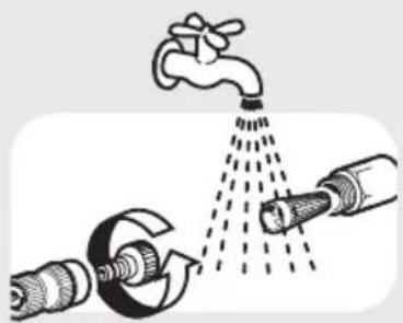
natural_image
Illustration of a faucet spraying water onto a pipe (no text or symbols)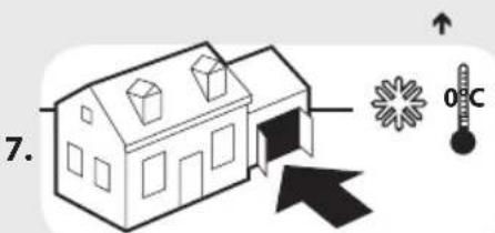
> SIMBOLI

ATTENZIONE!
PROGRAMMA MANUTENZIONI PROGRAMMATE
It is important to be careful on safety grounds.

ANT
> GENERAL INFORMATION
- This appliance's performance a userfriendliness make it suitable for PRO-FESSIONAL use.
- The appliance can be used for washing surfaces outdoors, whenever pressurised water is required to remove dirt.
- With special optional accessories, it can be used for foaming and sandingblasting, and for washing with a rotary brush for application to the gun.
> SAFETY PRECAUTIONS
• CAUTION! It is important to be careful on safety grounds.
- WARNING: This appliance is for outdoor use only.
- WARNING: Always disconnect the electricity and water supplies on completion of every job.
- WARNING: Never use the appliance if the electrical cable or important parts of the appliance are damaged, e.g. safety devices, high pressure hose, gun, etc.
- WARNING: This appliance has been designed for use with the detergent provided or the detergent specified by the manufacturer, such as a neutral shampoo based on biodegradable anionic surface active detergents. The use of other detergents or chemicals may put the appliance's safety at risk.
- WARNING: Never use the appliance with people in the vicinity, unless they are wearing protective clothing.
- WARNING: Do not direct the nozzle toward mechanical parts containing lubri-
cant grease, as the grease will dissolve and spread over the surrounding ground. Vehicle tyres/tyre valves may only be cleaned from a minimum distance of 30 cm, otherwise the vehicle tyre/tyre valve could be damaged by the high-pressure jet. The first indication of this is a discoloration of the tyre. Damaged vehicle tyres/tyre valves can be deadly dangerous.
- WARNING: High pressure jets may be dangerous if improperly used. Jets must never be pointed at people, animals, life electrical equipment or the appliance itself.
- WARNING: The hoses, accessories and high pressure couplings are important for the appliance's safety. Use only hoses, accessories and couplings recommended by the manufacturer (it is extremely important to protect these components against damage by avoiding their improper use and protecting them against bending, knocks and scratches).
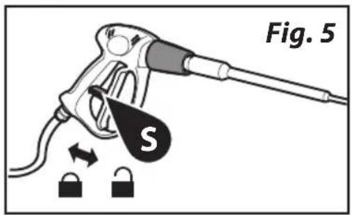
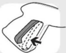
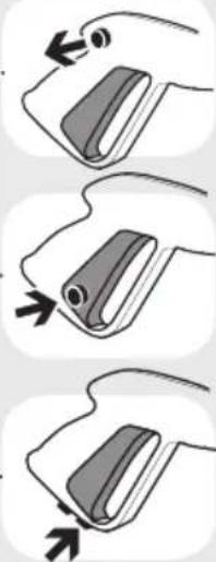
- WARNING: the gun is fitted with a safety catch. Whenever use of the machine is interrupted it is important to operate the safety catch to prevent accidental activation of the jet.
- Never point the jet at yourself or others to clean clothing or footwear.
- Never allow children or untrained people to use the appliance.
- Safety features: gun equipped with safety locking device, appliance equipped with (Class I) overload cutout, pump equipped with by-pass valve or shutdown device.
- The safety button on the gun is not there to lock the lever during operation, but to prevent its accidental operation.
- WARNING: Appliances not equipped with T.S. – Total Stop System: must not be left in operation for more than 2 minutes with the gun released. The recycled water heats up considerably, seriously damaging the pump.
- WARNING: Appliances equipped with T.S. – Total Stop System: these appliances should not be left in standby for more than 5 minutes.
- WARNING: Switch the appliance off completely (master switch on OFF) whenever it
is left unattended.
- WARNING: Every machine is tested in its operating conditions, so it is normal for a few drops of water to be left inside it.
- WARNING: Take care not damage the electric cable. Have a damaged power cord replaced immediately by an authorized service point or an electrical specialist.
- WARNING: Appliance with fluid under pressure. Keep a firm hold on the gun and be prepared to take the kickback pressure. Only use the high pressure nozzle provided with the appliance.
- WARNING: The high pressure hose is designed and produced to withstand high pressures. To avoid damage, it must be handled with special care. Misuse may lead to premature breakages or damage and cause the loss of warranty cover.
- WARNING: The appliance is not to be used by children or persons with reduced physical, sensory or mental capabilities, or lack of experience and knowledge, unless they have been given supervision or instruction.
- WARNING: Children being supervised not to play with the appliance.
- WARNING: Never start the high-pressure cleaner without first completely unwinding the high-pressure hose.
- WARNING: When winding and unwinding the pipe take care not to cause the high-pressure cleaner to overturn.
- WARNING: Before unwinding or winding the hose, switch the machine off and release the pressure in the hose itself (switching off).
> WATER SUPPLY
Water supply connection
Caution - Danger!
Only clean or filtered water should be used for intake. The delivery of the water intake tap should be equal to the double of the maximum pump range.
- Minimum delivery rate: 30 l/min.
- Maximum intake water temperature: 40°C
- Max inlet water pressure: 1Mpa
Place the cleaner as close to the water supply system as possible.
Water supply from the water main
- Connect a supply hose (not included) to the water inlet of the unit (ref. 1, pos. 7) and to the water supply (max. pressure 10 bar).
- Connect high pressure hose to the machine connection (ref. 1, pos. 6) and turn on the water tap.
The cleaner can be connected directly to the mains drinking water supply hose is fitted with a backflow preventer valve as per current regulations in force.
Make sure that the hose is at least ∅ 13 mm and that it is reinforced.
Failure to comply with the above conditions causes serious mechanical damage to the pump and the loss of warranty cover.
> HIGH PRESSURE HOSE
- WARNING: The high pressure hose is designed and produced to withstand high pressures. To avoid damage, it must be handled with special care.
Misuse may lead to premature breakages or damage and cause the loss of warranty cover. (See illustrations).
> ELECTRICITY SUPPLY
- The appliance's electrical connection must comply with the IEC 364 standard.
Before connecting the appliance, make sure that the nameplate data are the same as those of the electrical mains and that the socket is protected by a differential security breaker with tripping sensitivity below 0.03 A - 30 ms. - If the appliance's plug is not compatible with the socket, have the socket replaced with another of suitable type by professionally qualified staff.
- Never use the appliance in ambient temperatures below 0^ C if it is equipped with a PVC (H VV-F) cable.
- WARNING: Inadequate extension cords can be dangerous.
- If an extension lead is used, the plug and socket must be watertight and the cable
must have the dimensions shown in the table below.
| 230-240V 400-415V | |
| 3G 2,5 mm ^2 | 4G 2,5 mm ^2 |
| max 20 m max 30 m | |

Total Stop 24V (if fitted)
Machines equipped with delayed, low-voltage Total Stop with intelligent switch-off:
When the machine is working, by releasing the gun lever, after approximately 15 seconds the motor stops automatically to prevent component wear during the pump by-pass phase (motor in stand-by). By pressing the gun lever the motor starts automatically.
- WARNING: do not leave the stand-by mode active for more than 5 minutes.
If the machine remains in stand-by mode for more than 20 minutes, it switches off automatically and completely: in fact, by pressing the gun lever the machine does NOT start working.
For this reason, if you need to start the machine it is necessary to set the switch to (0) "OFF" and then to (1) "ON".
At the end of the operation, set the switch to "OFF".
Activate hand spray gun until device is pressure less.
PRESSURE REGULATOR:
If the appliance is equipped with a pressure regulator:
- when the pressure is set to minimum the T.S. may not trigger. Therefore, do not allow the appliance to function in by-pass for more than 1 minute.
- do not act on the gun lever too frequently (this may cause a malfunction).
> SUITABLE USE OF THE MACHINE
The performances of the machine are suitable for a professional use. Structural technologies have been studied to assure high reliability and safety levels, and long life. It is absolutely forbidden to use the machine in potentially explosive environments or areas.
The working temperature must range between +5^ and +50^ C. It is forbidden to carry out any modification to the structure and to any elements of the machine.
CORRECT USE OF THE MACHINE
- The cleaner must be placed on a firm, stable surface and must be horizontal.
- In case of operation indoors, adequate ventilation and gas venting must be assured.
- Whenever using the high-pressure cleaner, users are urged to hold the gun in the correct position, with one hand on the grip and the other on the spray rod.
- The water jet must never be pointed at the electrical cables or at the machine.
> INSTALLATION AND START-UP
INSTALLATION
The equipment must be installed on a sturdy, perfectly flat surface. Fasten to the floor with 4 steel wedges ∅ 1 (see ref. 2).
The floor must be suitable for this kind of fastening.
1 ^ST START-UP
When starting up for the first time or after a long period out of use, connect the intake line only for a few minutes so that any dirt is vented from the delivery outlet.
ELECTRICAL CONNECTION
Check that the mains voltage is the same as that of your machine, indicated on the technical data plate. Your electrical system must be constructed by qualified technicians capable of working in accordance with the requirements of the regulations in force (earth connection, fuses, differential security breaker, etc).
The connection to the mains must be carried out by qualified personnel.
Connect a supply cable whose diameter is suitable for the power used by the equipment (see Technical Data).
Connect the ground cable together with the other ground cables located inside the electric box.
In case of failure to comply with one of the
regulations stated above, the manufacturer declines all responsibility for the staff and provides no warranty.
FILLING UP WITH FUEL
Fill the tank with the fuel indicated on the technical data plate (Diesel, ref. 1, pos. 14).
Avoid that the tank is empty when the machine is running in order not to damage the fuel pump.
- Incorrect fuel shall not used as they as provide hazard.
Fill up the detergent tank with the suggested products, suitable for the kind of washing to be carried out (ref. 1, pos. 13).
- CAUTION: Make use only of liquid detergent, do not absolutely use acid or too much alkaline products. We suggest you to make use of our products, which have been studied for the use with washer machines.
START-UP
Switch on the machine by pressing the switch (ref. 1, pos.1) and leave it to run for a few minutes to eliminate any dirt and air bubbles from the water circuit, then switch it off, connect the high pressure line to the spray gun (ref. 3) and fit the spray rod (ref. 4). Make sure that the detergent regulator is in the closed position.
When the machine is running again, check that the jet is even; otherwise, clean the nozzle to remove any dirt. Wait a few seconds for the operating pressure to be reached, then operate the gun for two or three short bursts.
To wash with hot water, press the switch (ref. 1, pos. 4) and turn the thermostat (ref. 1, pos. 2) to the desired temperature setting. To mix detergent or disinfectant to the water jet, adjust the quantity on the detergent pump or the control cock (if any).
> LANCE ASSEMBLY
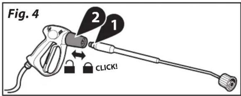
To fit the lance to the gun, it is sufficient to insert the threaded end of the lance (ref. 4, pos. 1) into the hole on the gun (ref. 4, pos. 2); then screw the lance as shown by the arrow (A) until the connection is tight.
> DETERGENT SUCTION
The detergent is automatically aspirated when you press the detergent switch (fig. 1, pos. 5).
• CAUTION: Make use only of liquid detergent, do not absolutely use acid or too much alkaline products. We suggest you to make use of our products, which have been studied for the use with washer machines.
> CONTROL COMPONENTS
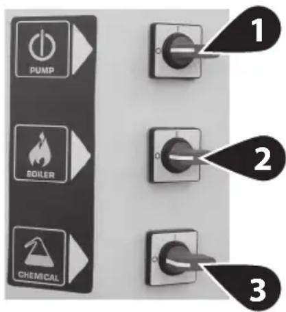
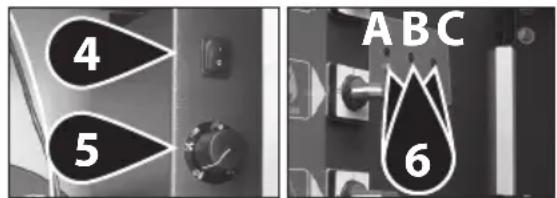
CONTROL SWITCHES
1 Motor pump switch
2 Burner switch
3 Detergent switch
4 Internal switch
5 Water temperature controller
6 Pilot lights
4 - position ON: enables the external controls
- position OFF: disables the external con-
trols.
6 A: Motor pump ON green pilot light
B: Leak pilot light
- flashes when the pistol lever is repeatedly operated in a short time or when a leak occurs in the high pressure circuit.
Remove the leak, referring to an authorized service centre.
- remains ON when the machine is left in stand-by for over 20 minutes. Switch on and off the motor pump switch.
C: Burner switch
- flashes when the gasoil tank is empty; the burner is stopped. Refuel.
- remains ON when the burner switches on.
> GUN SAFETY DEVICE
Whenever the machine has to be stopped, it is important to engage the safety catch (S, ref. 5) on the gun so that it cannot be operated accidentally.
> DESCALING
The descaling procedure must be carried out periodically with specific products. The interval depends on the hardness of the water. This operation should be carried out by our after-sales service, since the descaling product may cause wear of components. Comply with the regulations in force when disposing of the descaling agent.
• Liquid softener tank (if any)
Fill the softener tank with our products (in all cases, with non corrosive products). The dispensing rate is set at a medium value; the After Sales Services will be able to adapt the setting to local conditions.
> MAINTENANCE
SCHEDULED MAINTENANCE PLAN Visit website www.lavorservice.com and download the scheduled maintenance plan.
IMPORTANT: Before doing any work on the cleaner, discharge the pressure and disconnect the electricity and water supplies.
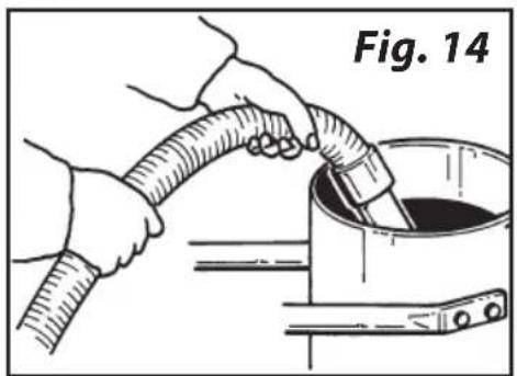
Check the oil level periodically. The oil must be changed for the first time after 50 working hours, with subsequent changes every 500 hours. SAE 20/30 oil is recommended - Oil capacity 0,7 Kg
CHECKING THE WATER INTAKE FILTER
Inspect and clean the water intake filter (ref. 6) on the intake union periodically. This is important to prevent fouling which may impair operation of the pump.
REPLACING THE SPRAY ROD NOZZLE
Replace the nozzle when the pressure drops below the normal values.
ELECTRIC MOTOR
If the motor malfunctions, it cuts out. Wait 5-10 minutes before restarting. If the problem persists, refer to the "TROUBLESHOOTING" section. If you are still unable to eliminate the problem, stop using the machine and contact an Authorized Service Centre.
ELECTRICAL CORD
- WARNING: Take care not damage the electric cable. Have a damaged power cord replaced immediately by an authorized service point or an electrical specialist.
CLEANING THE FUEL FILTER
Check the fuel filter (ref. 7) periodically and replace if it has deteriorated or is excessively dirty.
> ELECTRIC DIAGRAM
See illustrations, page 6.
> WATER DIAGRAM
See illustrations, page 6.
> TROUBLESHOOTING
Before doing any work on the machine, discon-
nect the electricity and water supplies and discharge the pressure. Proceed systematically to identify faults following the chart below; if you are still unable to eliminate the problem, call in the Authorized After-Sales Service.
| Fault | When the main switch is turned on the machine does not start |
| Cause • Plug not properly connected.• Connection panel fuses are burnt out. | |
| Repair • Carefully check the plug and the electric cable.• Check them and replace them. |
| Fault | The motor hums but does not start |
| Cause • | A phase is missing (in three phase models).Lows voltage.High pressure pump is blocked. |
| Repair • | Contact an authorised service centre.Contact an authorised service centre.Contact an authorised service centre. |
| Fault | The motor stops suddenly or after a while |
| Cause • | The motor-protecting switch is on because of insufficient mains voltage. |
| Repair • Check the value of the mains voltage.• Contact an authorised service centre. | |
| Fault | When the lance is turned on pressure values decrease and increase |
| Cause • | The nozzle is either clogged or deformed.Either boiler coil or lance are clogged with limestone. |
| Repair • Either clean it or replace it.Descaling. | |
| Fault | To much vibrations at the delivery |
| Cause • | The valve are worn out or dirty. |
| Repair • Check and/or replace. | |
| Fault | The pump does not reach the fixed pressures |
| Cause • The pump sucks air.• The valves are worn out.• The setting valve area is worn out.• The nozzle is unsuitable or worn out.• The seals are worn out. | |
| Repair • Check the suction pipes.• Check and/or replace.• Contact an authorised service centre.• Contact an authorised service centre. | |
| Fault Irregular pressure fluctuations | |
| Cause • The suction and/or delivery valves are worn out. Presence of foreign matters in the valves, which generate bad functioning. Air suction. The seals are worn out. | |
| Repair • Check and/or replace.• Check and clean the replace.• Check the suction pipe.• Check and/or replace the seals. |
| Fault Pressure leakage | |
| Cause • The nozzle is worn out. The suction and/or delivery valves are broken or down. Presence of foreign matters in the valves, which generate the valves bad functioning. The setting valve area is worn out. The seals are worn out. | |
| Repair • Replace the nozzle. Check and/or replace the valves. Check and clean the valves. Check and/or replace the setting valve area. Replace the seals. |
| Fault Noisiness | |
| Cause • Air suction. | The suction and/or delivery valve springs are broken or down.Foreign matters in the suction and delivery valves.The bearings are worn out.Extreme liquid temperature. |
| Repair • Check the suction pipes. | Replace the valve springs.Check and clean the suction and delivery valves.Replace the bearings.Reduce the liquid temperature. |
| Fault Water is in the oil | |
| Cause • | The O-ring casing is worn out.High moisture in the air.The seals are completely worn out. |
| Repair • Check and/or replace the O-ring.Replace the oil with double frequency in respect of the one suggested.Replace the seals. | |
| Fault | Filtrations of water from the drains between casing and head |
| Cause • The seals are worn out.• The piston is worn out.• The O-ring of the piston cap is worn out. | |
| Repair • Replace the seals.• Replace the piston.• Replace the seal. | |
| Fault | Filtrations of oil from the drains between head and casing |
| Cause • | O-ring seals of casing are worn out. |
| Repair • Replace the seals. | |
| Fault | Turning on the burner switch the boiler does not start |
| Cause • No fuel. Fuel filter is clogged.Fuel pump is either blocked or burnt out.Damaged thermostat.Ignition spark insufficient or totally lacking.The space among the electrodes is not correct.Burn out fuse. |
| Repair • Check the level in the tank and check whether the rigid suction pipe is clean.Replace the line filter.Replace it.Replace it.Contact an authorised service centre.Check the positioning.Replace it. |
| Fault Water is not hot enough | |
| Cause • Poor boiler performance. • Boiler coil clogged with limestone. | |
| Repair • Clean burner nozzle filter. • Clean fuel filter. • Check diesel pump pressure • Descaling. |
| Fault | Too much smoke from the chimney |
| Cause • Combustion is not correct.• Impurities or water in the fuel. | |
| Repair • Clean fuel filter.• Clean the boiler.• Empty the tank and clean it carefully.• Clean fuel filter as well. | |
| Fault Insufficient detergent suction |
| Cause • No detergent in the tank.Incrusted injector.Either coil or tube or lance are clogged. |
| Repair • Fill the detergent tank.Clean it.Either cleaning or descaling. |
> REPAIRS - SPARE PARTS
For any problems not mentioned in this manual, or if the machine breaks down, you are urged to contact an Authorized After-Sales Service for the relative repair or for any replacement of components with original spare parts. Use exclusively original replacement parts.
> BOILER CLEANING
- ATTENTION: For all maintenance of the boiler, of the high pressure pump and of the machine, it is necessary to address to qualified personnel or to an authorized assistance center.
The boiler cleaning must be periodically executed every 180 ÷ 200 hours of working proceeding as follows:
Carefully remove the nozzle holder flange and the electrodes holder (boiler head, ref. 8).
Clean with compressed air the nozzle filter and check the electrodes position. (ref. 9).
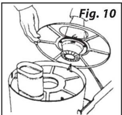
Remove the boiler cap unscrewing the 3 nuts, clean the deflector (ref. 10).
Manually take away the interior cap (ref. 11).
Unscrewing the locking nuts (ref. 12) and take the boiler coil out.
Clean the coil by an iron brush (ref. 13).
Suck the residuums from the boiler (ref. 14).
Replace every parts doing the operations in the inverse way.
Please note. The general checking and combustion regulation must be periodically
executed by specialized personnel as prescribed by the law.
> WARRANTY CONDITIONS
All our machines are subjected to strict tests and are covered against manufacturing defects in accordance with applicable regulations (minimum 12 months). The warranty is effective from the date of purchase. If your high pressure washer or accessories are handed in for repair, a copy of the receipt must be enclosed.
Guarantee repairs are being made on the following conditions: - That defects are attributable to flaws or defects in materials or workmanship. - That the directions of this instruction manual have been thoroughly observed. - That repair has not been carried out or attempted by other than authorized service staff. - That only original accessories have been applied. - That the product has not been exposed to abuse such as knocks, bumps or frost. - That only water without any impurities has been used. - That the high pressure washer has not been used for rental nor used commercially in any other way.
The following are not included in the warranty: - Parts subject to normal wear. - The high-pressure tube and optional accessories. - Accidental damage, caused by transport, neglect or inadequate treatment, incorrect or improper use and installation failing to comply with the indications in the instruction manual. - The warranty shall not cover any cleaning operations to which the operative components may be subjected.
Repairs under this guarantee include replacement of defective parts, exclusive of packing and postage/carriage. The warranty shall not cover replacement of the machine or extension of the guarantee resulting from a breakdown. The manufacturer declines all responsibility for damage to persons or property caused by bad installation or incorrect use of the machine.
WARNING! Failures, such as clogged nozzles, valves and mechanism blocked due to limestones, damaged pressure cleaner accessories (like kinked high pressure hose) and/or appliances normally working without any defects ARE NOT COVERED BY THE WARRANTY.
> DISPOSAL (WEE)

As the owner of electrical or electronic equipment, the law (in accordance with the EU Directive 2012/19/EU on waste electrical and electronic equipment and rational laws of the EU Member States that implemented this Directive) prohibits you disposing of this product or its electrical /ronic accessories as municipal solid waste obliges you to make use of the appropri- waste collection facilities. The product can disposed of by returning it to the distribu- then a new product is purchased. The new product must be equivalent to that being dis- d of. Disposing of the product in the envi- ment can cause great harm to the environ- itself and human health.
The symbol in the figure indicates the urban waste containers and it is strictly prohibited to dispose of the equipment in these containers. Non-compliance with the regulationis spulated in the Directive 2012/19/EU and the decrees implemented in the various EU Member States is administratively punishable.
• SYMBOLES

ATTENTION!
REPLACEMENT DE LA BUSE DE LA LANCE
> CONDITIONS DE GARANTIE
www.lavorservice.com
LwA 89dB(A) K (uncertainty) 2dB (A)
LwA 91dB(A)
• Livello pressione acustica
- Acoustic pressure
• Niveau de pression acoustique
• Schalldrückpegel
• Nivel de ruido
• Geluidsdrukniveau
• Nível da pressão acústica
Livello di potenza sonora misurato
EN Acoustic power measured
FR Niveau du puissance sonore mesuré
DE Abgemesstes Schalleistungsniveau
ES Nivel de potencia acústica mesurado
NL Geluidsdrukniveau LwA gemeten
PT Nível de potencia acústica mensurada
Livello di potenza sonora garantito
EN Acoustic power granted
FR Niveau du puissance sonore garanti
DE Garantiertes Schalleistungsniveau
ES Nivel de potencia acústica garantido
NL Geluidsdrukniveau LwA gegarandeerd
PT Nível de potencia acústica garantida
LwA 89dB(A) K (uncertainty) 2dB (A)
LwA 91dB(A)
• Geluidsdrukniveau
EN Acoustic pressure
Acoustic power granted
- HHPV HHPX
- (FR)
- > SCHEMA ELETTRICO • ELECTRIC DIAGRAM • SCHEMA ELECTRIQUE • ELEKTROSCHEMA • ESQUEMA ELÉCTRICO • ELEKTRICITEITSSCHEMA • HΛEKTPIKO ΔIΑΓΡΑΜΜΑ
- > SCHEMA IDRICO • WATER DIAGRAM • SCHEMA HYDRAULIQUE • WASSERUMLAUFSCHEMA • ESQUEMA HÍDRICO • WATERCHEMA • ΣΧΕΔΙΟ ΥΔΡΕΥΣΗΣ
- OPTIONAL
- FILTRO DOSATORE DI SALI POLIFOSFATI IN CRI STALLI,
- THREE-WAY POLYPHOSPHATE SALT CRYSTALS DOSING FILTER, FOR WATER HEATERS.
- non PROPORTIONAL filter for WATER HEATER
- WARNING!
- RECHARGE STEPS :
- CRYSTALS OF POLYPHOSPHATE
- FR
- FILTRE DISTRIBUTEUR TROIS VOIES DE SEL POLYPHOSPHATES EN CRISTAUX,POUR CHAUDIE RES A EAU
- > SIMBOLI
- ATTENZIONE!
- PROGRAMMA MANUTENZIONI PROGRAMMATE
- > GENERAL INFORMATION
- > SAFETY PRECAUTIONS
- > WATER SUPPLY
- Water supply connection
- Caution - Danger!
- Water supply from the water main
- > HIGH PRESSURE HOSE
- > ELECTRICITY SUPPLY
- Total Stop 24V (if fitted)
- PRESSURE REGULATOR:
- > SUITABLE USE OF THE MACHINE
- CORRECT USE OF THE MACHINE
- > INSTALLATION AND START-UP
- INSTALLATION
- ST START-UP
- ELECTRICAL CONNECTION
- FILLING UP WITH FUEL
- START-UP
- > LANCE ASSEMBLY
- > DETERGENT SUCTION
- > CONTROL COMPONENTS
- CONTROL SWITCHES
- > GUN SAFETY DEVICE
- > DESCALING
- > MAINTENANCE
- CHECKING THE WATER INTAKE FILTER
- REPLACING THE SPRAY ROD NOZZLE
- ELECTRIC MOTOR
- ELECTRICAL CORD
- CLEANING THE FUEL FILTER
- > ELECTRIC DIAGRAM
- > WATER DIAGRAM
- > TROUBLESHOOTING
- > REPAIRS - SPARE PARTS
- > BOILER CLEANING
- > WARRANTY CONDITIONS
- > DISPOSAL (WEE)
- • SYMBOLES
- ATTENTION!
- REPLACEMENT DE LA BUSE DE LA LANCE
- > CONDITIONS DE GARANTIE
- LwA 89dB(A) K (uncertainty) 2dB (A)
- LwA 91dB(A)
Brand : Lavor
Model : HHPV
Category : Pressure washer