LITE PRO 1510LP - Pressure washer Lavor - Free user manual and instructions
Find the device manual for free LITE PRO 1510LP Lavor in PDF.


| Product Type | High Pressure Washer |
| Brand | Lavor |
| Model | LITE PRO 1510LP |
| Tension d'alimentation | 230 V - 50 Hz |
| Power Consumption | 2.9 kW |
| Recommended Fuse | 16 A |
| Maximum Pressure | 150 bar (15 MPa / 2176 psi) |
| Maximum Flow Rate | 600 l/h |
| Max. Feed Water Temperature | 60 °C |
| Min. Feed Water Temperature | 5 °C |
| Dimensions (L x W x H) | 460 x 200 x 325 mm |
| Weight | 27 kg |
| Sound Pressure Level | 82.2 dB(A) |
| Sound Power Level | 96 dB(A) |
| Hand-Arm Vibration | 2.3 m/s² |
| Safety Device: Automatic Stop (Total-Stop) | Yes, when the gun is closed (pressure > 20 bar) |
| Safety Device: Amperometric Cut-off | Yes |
| Safety Device: Limiting/Regulating Valve | Yes |
| Safety Device: Gun Trigger Lock | Yes |
| Maintenance: Water Inlet Filter | Weekly cleaning |
| Maintenance: Pump Oil Level | Monthly check via indicator |
| Included Accessories | High pressure hose, gun, lance tube, detergent suction kit, nozzle cleaning tip |
| Options | BA backflow preventer, sandblasting lance, drain cleaning nozzle, rotary lance, foam lance |
Frequently Asked Questions - LITE PRO 1510LP Lavor
User questions about LITE PRO 1510LP Lavor
0 question about this device. Answer the ones you know or ask your own.
Ask a new question about this device
Download the instructions for your Pressure washer in PDF format for free! Find your manual LITE PRO 1510LP - Lavor and take your electronic device back in hand. On this page are published all the documents necessary for the use of your device. LITE PRO 1510LP by Lavor.
USER MANUAL LITE PRO 1510LP Lavor
IT • IDROPULITRICI ELETTRICHE AD ACQUA FREDDA
natural_image
Industrial pressure pump with motor, pressure gauges, and hose (no visible text or symbols)LITE 1510 XP
natural_image
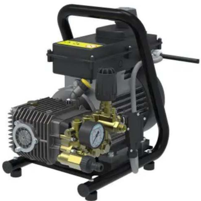
Industrial pressure pump with black housing and yellow internal components (no visible text or symbols)LITE PRO 1510 LP


natural_image
Close-up of a mechanical pressure pump assembly with orange tool and brass fittings (no visible text or symbols)

CARATTERISTICHE E DATI TECNICI
(*) Measurements taken in compliance with EN 60335-2-79
The characteristics and specifications are guidelines only. The manufacturer reserves the right to make all modifications to the equipment deemed necessary.
IDENTIFICATION OF COMPONENTS
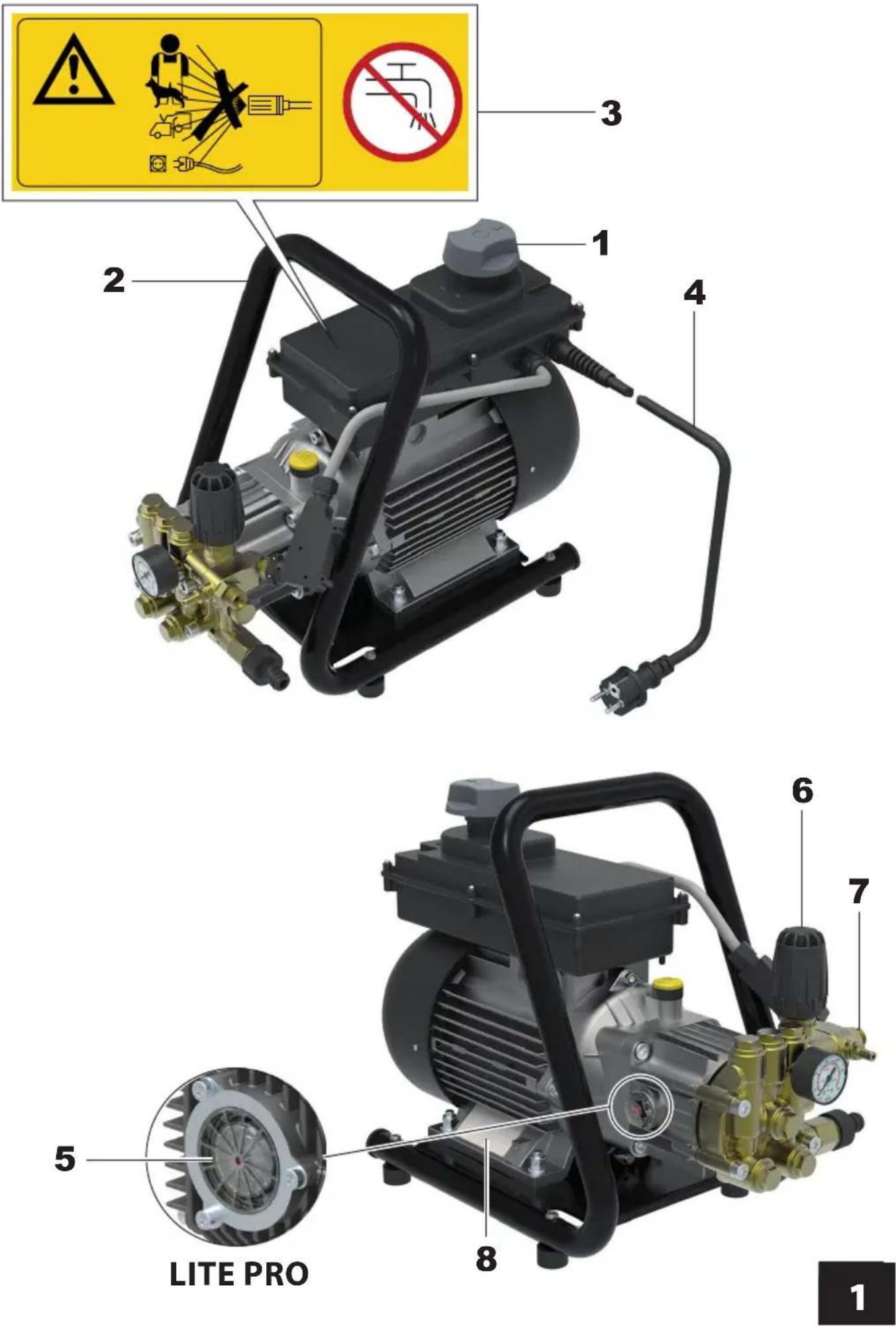
Refer to figures 1, 2, 3, 4 and 5.
- TMaster switch
- Transport grip
- Warning plate. Informs about residual risks: not to be used to wash people, animals, electrical apparatus and the high-pressure cleaner itself. Warns that the machine is unsuitable for connecting up to the drinking water mains (to connect up to the water mains, a BA type mains disconnector will be required which can be purchased from your dealer).
- Power cable
- Oil level indicator [LITE PRO]
- Pressure adjustment knob
- Water outlet connection
- Identification plate. Shows the serial number and main technical specifications.
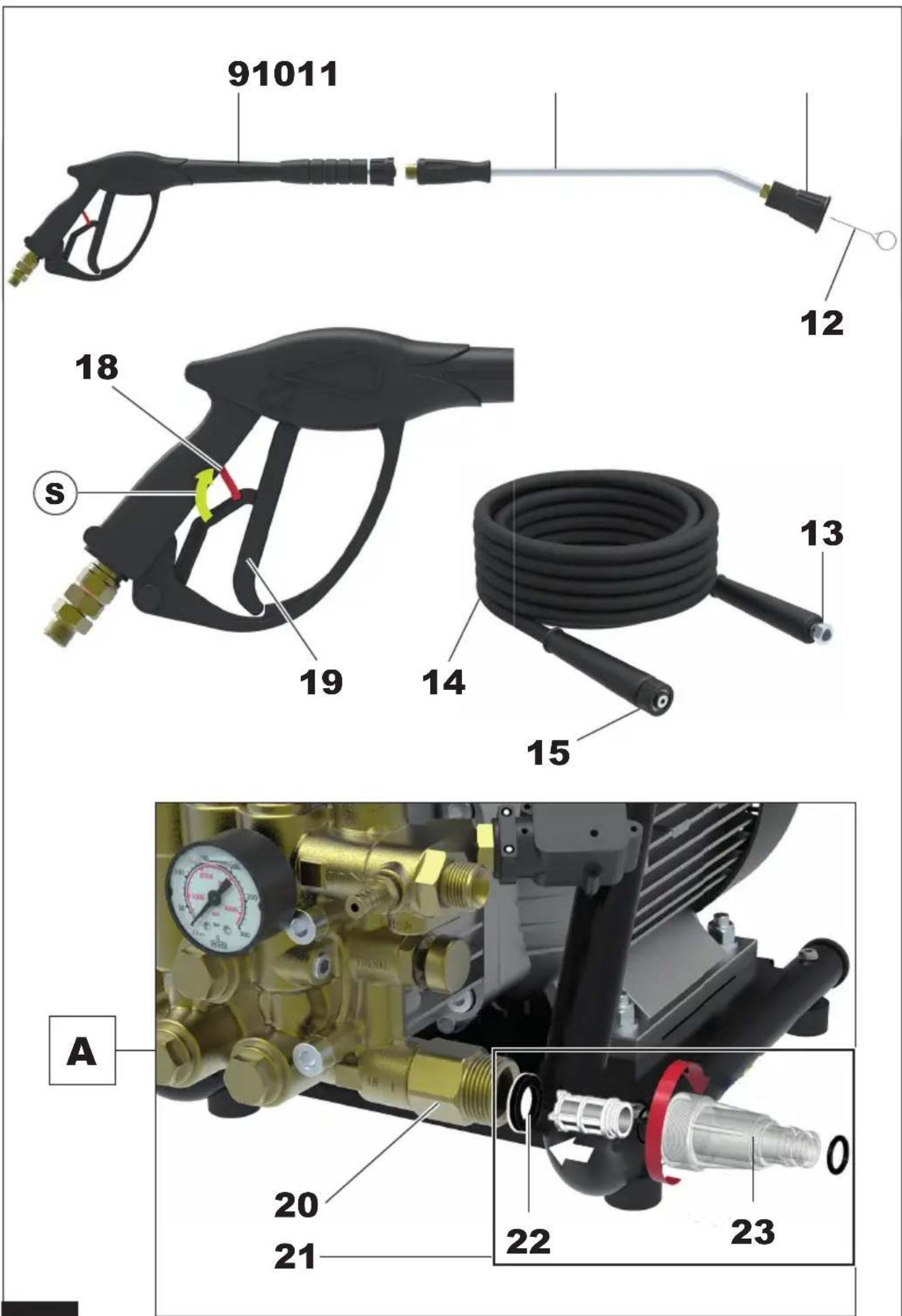
- Spray gun
- Lance hose
-
Nozzle holder head
-
Nozzle cleaning pin
- High-pressure hose connection
- High-pressure hose
- High-pressure hose quick coupling
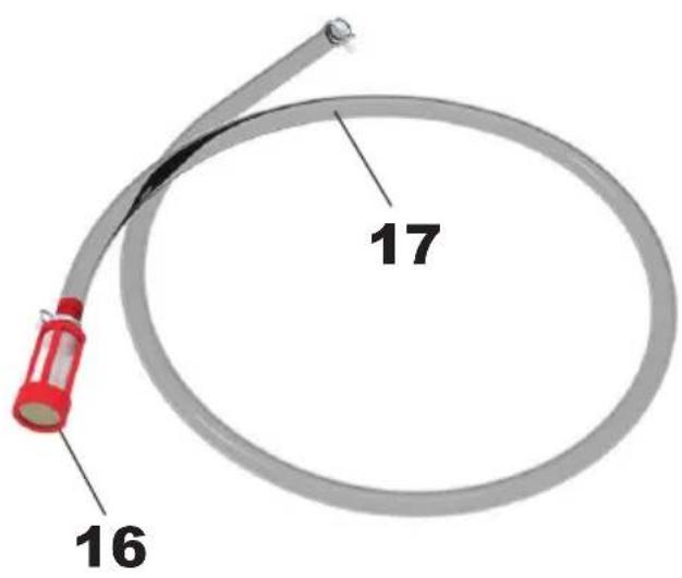
- External detergent suction hose filter
- External detergent suction hose
- Spray gun lever safety stop
- Spray gun lever
- Water inlet connection
- Water inlet filter
- Water inlet quick-fit connection seal
- Water inlet quick-fit connection
- External tank detergent suction coupling
- Elastic clamp for fastening the detergent suction hose
- BA type water mains disconnector (not supplied)
SAFETY DEVICES
- Ampere cut-out protection device.
This device stops the high-pressure cleaner operation in the event of excessive power absorption. If it trips, proceed as follows:
- move the master switch (1) to "0" position and remove the plug from the power socket;
- press the spray gun lever (19), so as to release any residual pressure;
- wait 10÷15 minutes for the high-pressure cleaner to cool down;
- make sure the instructions for connection to the power supply are complied with (refer to the INSTRUCTION MANUAL - SAFETY PRECAUTIONS), with special reference to the extension used;
- fit the plug back in the socket and repeat the start procedure described in the paragraph "OPERATION".
- Pressure unloader/regulation valve.
Valve suitably set by the Manufacturer, which permits regulating the operating pressure by means of the knob (6) and which allows the pumped fluid to return to pump suction, preventing the occurrence of hazardous pressures when the spray gun is closed or whenever an attempt is made to set pressure values above max. allowed pressure.
- Spray gun lever lock device.
Safety stop (18) which allows locking the lever (19) of the spray gun (9) in closed position, thus preventing accidental operation (fig. 2, position S).
STANDARD FITTINGS
Make sure the following are contained in the purchased product pack:
• high-pressure cleaner;
• high-pressure delivery hose with quick coupling;
- spray gun;
- lance hose;
- suction connection kit;
• external detergent suction hose kit;
- instruction manual - safety precautions;
- instruction manual - operation and maintenance;
- warranty certificate;
• after-sales centre booklet;
• EC declaration of conformity;
- nozzle cleaning pin.
In case of problems, contact your dealer or an authorised after-sales centre.
OPTIONAL ACCESSORIES
The standard fittings of the high-pressure cleaner can be integrated with the following range of accessories:
- BA type water mains disconnector: mandatory for connecting up to the drinking water mains.
- sandblasting lance: designed to clean surfaces, eliminating rust, paint, scale, etc.;
- drain cleaning kit: designed to unblock pipes and ducts;
- rotating-nozzle lance: designed to remove resistant dirt;
- foam lance: designed for more effective detergent distribution;
- lances and nozzles of various types.
INSTALLATION - FITTING ACCESSORIES
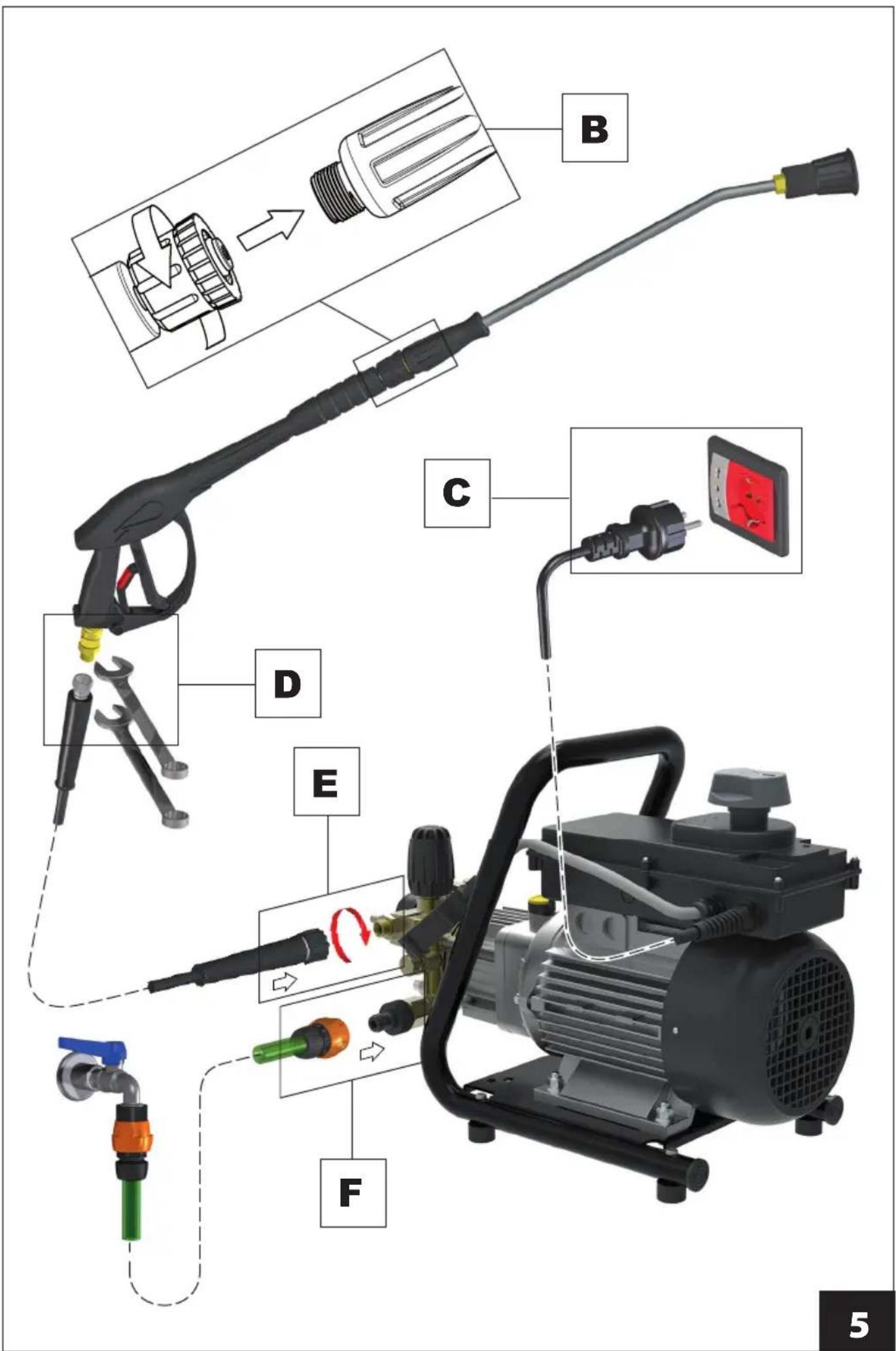
- Connect the quick coupling (15) of the hose (14) to the water outlet connection (7), screw down and secure. Operation E in fig. 6.
- Screw up the connection (13) of the high-pressure hose to the thread of the spray gun (9) and tighten well using two 22 mm fixed wrenches (not supplied). Operation D in fig. 6.
- Fit the filter (21) in the water inlet connection (20). Fit the seal (22) in the water inlet quick-fit connection (23) and screw up to the connection (20). Operation A in fig. 2.
OPERATION - PRELIMINARY ACTIVITIES
- Move the high-pressure cleaner to work position.
• Completely unwind the high-pressure hose (14). - Attach a supply pipe to the water inlet's quick connection (23) using a normal garden connector. Operation F in fig. 6.
- Open the water supply tap and make sure this is not dripping;
- if the connection is made to the drinking water mains, a BA type water mains disconnector (26) must be used, in conformity with EN 12729 standard, and available from your dealer (fig. 5). With regard to its use, refer to the relative instruction manual;
- in case of supply from a water tank, introduce the suction hose inside the tank and make sure the vertical distance between the water level and the pump is no more than 1.5 m (4.9 ft). Operation G in fig. 5.
- Make sure the master switch (1) is on "0" position and insert the plug. Operation C in fig. 6.
- Move the master switch (1) to position "1".
- Press the spray gun lever (19) and wait for a continuous jet of water to come out;
- Move the master switch (1) to "0" position and connect the lance hose (10) to the spray gun (9), tightening well. operation B in fig. 6.
STANDARD OPERATION (HIGH PRESSURE)
- Make sure the nozzle holder head (11) is not in the detergent dispensing position (refer to "OPERATION WITH DETERGENT" paragraph).
- Start the high-pressure cleaner again moving the master switch (1) to position "1".
- Press the gun spray lever (19), making sure the spray of the nozzle is even and this is not dripping.
- If necessary, adjust the pressure by turning the knob (6). Turn clockwise to increase pressure, anticlockwise to decrease it.
OPERATION WITH DETERGENT
The detergents recommended by the Manufacturer are over 90% biodegradable.
For instructions on how to use them, refer to the indications on the label of the detergent pack.
- Move the master switch (1) to "0" position.
- Insert the detergent hose (17) in the connection (24) on the pump head, loosening the elastic clamp (25) using pliers as shown in fig. 3.
- Introduce the other end of the hose (17) including the filter (16) into the external tank, which will already have been prepared with the detergent with the required dilution. In this case as well, follow the suggestions relating to dosage shown on the label of the detergent pack.
- Operate on the nozzle holder head (11) as shown in fig. 3 - position A.
- Start the high-pressure cleaner again, moving the master switch (1) to position "1" and operate the lever (19): suction and mixing occur automatically as the water flows through.
- To stop the supply of detergent and restore high-pressure operation, stop the high-pressure cleaner moving the master switch (1) to "0" position and operate on the head (11) as shown in fig. 3 - position B.
STOPPING OPERATION
- With operating pressures above 20 bar / 290 psi, the high-pressure cleaner automatically stops by releasing the spray gun lever (19), through the Total-Stop device. It starts operating again when pressing the spray gun lever.
STOP
- Completely close the water supply tap (or remove the suction hose from the water tank).
- Empty the water from the high-pressure cleaner, allowing this to operate for a few seconds with the spray gun lever (19) pressed.
- Move the master switch (1) to "0" position.
- Remove the plug from the power socket.
- Eliminate any residual pressure in the high-pressure hose (14), by keeping the spray gun lever (19) pressed for a few seconds.
- Wait for the high-pressure cleaner to cool down.
DECOMMISSIONING
- Re-wind the high-pressure hose (14) carefully, avoiding any folds.
- Re-wind the power cable (4) carefully.
- Store the high-pressure cleaner in a dry and clean place, making sure not to damage the power cable and the high-pressure hose.
ROUTINE MAINTENANCE
Perform the operations described in the "STOP" paragraph, following the chart shown below.
| MAINTENANCE SCHEDULE | JOB |
| After every use | Check the power cable, high-pressure hose, connections, spray gun and lance hose. If any of these is damaged, do not use the high-pressure cleaner and contact a Skilled Technician. |
| WeeklyClean the water inlet filter (21). | Unscrew the quick-fit connection (23) and take out the filter (21). Generally speaking, to clean this all that need be done is pass the filter under a jet of running water or blow on it with compressed air. In the most difficult cases, use an anti-scale product or replace the filter. To buy spares contact an authorised after-sales centre. Fit the filter back on and screw the quick-fit connection back on. |
| MonthlyClean the nozzle. | Generally speaking, to clean the nozzle, it is enough to pass the pin (12) provided through the nozzle hole. If this is not successful, change the nozzle. Buy this from an authorised after-sales centre. The nozzle can be changed using a 14 mm wrench (not supplied).Clean the detergent suction filter (16).Generally speaking, to clean the filter, all you need do is pass it under a jet of running water or blow it with compressed air. In the most difficult cases, use an anti-scale product or replace it. Only buy spares from authorised after-sales centres.Check the pump oil level [LITE PRO].Use the indicator (5) (fig. 1). If topping up is required, contact a Skilled Technician. |
SPECIAL MAINTENANCE
Special maintenance jobs must only be performed by a Skilled Technician, following the table below (indicative data).
| MAINTENANCE SCHEDULE | JOB | |
| Every 200 hours • Check the pump (water) hydraulic circuit. • Check the pump fastening. | ||
| Every 500 hours • Pump oil change.• Check the pump suction/delivery valves.• Check the tightness of the pump screws. | • Check the pump regulation valve.• Check the safety devices. | |
TROUBLESHOOTING
PROBLEMS CAUSES REMEDIES
| When the switch (1) is moved to position “1”, the high-pressure cleaner does not start. | Tripping of system cutout device to which the high-pressure cleaner is connected (fuse, RCCB, etc.). | Reset the cutout device.IN CASE THIS TRIPS AGAIN, DO NOT USE THE HIGH-PRESSURE CLEANER AND CONTACT A SKILLED TECHNICIAN. |
| The plug is not properly fitted. Disconnect the plug and fit it back correctly. | ||
PROBLEMS CAUSES REMEDIES
| The high-pressure cleaner vibrates a lot and is noisy. | Water inlet filter (21) dirty. Follow | the indications of the “ROUTINE MAINTENANCE” paragraph. |
| Suction of air. Check the integrity of the suction circuit. | ||
| Not enough water supply or too much priming depth. | Make sure the tap is completely open and that the water mains flow or priming depth are in conformity with the indications of the paragraph “OPERATION - PRELIMINARY ACTIVITIES” fig. 5 - Operation G. | |
| The high-pressure cleaner fails to reach maximum pressure. | Unloader/regulation valve set at a lower value than the maximum one. | Turn the knob (6) clockwise. |
| Nozzle holder head (11) in low-pressure mode (fig. 3 - Position A). | Refer to fig. 3 - Position B. | |
| Worn nozzle. Replace the nozzle as indicated in the “ROUTINE MAINTENANCE” paragraph. | ||
| Not enough water supply or too much priming depth. | Make sure the tap is completely open and that the water mains flow or priming depth are in conformity with the indications of the paragraph “OPERATION - PRELIMINARY ACTIVITIES” fig. 5 - Operation G. | |
| Faulty operation of the BA type water mains disconnector | See table in relative instruction manual. | |
| Low detergent suction Nozzle holder head (11) not in low-pressure mode (fig. 3 - Position B). | Refer to fig. 3 - Position A. | |
| Detergent suction filter (16) clogged. | Follow the indications of the “ROUTINE MAINTENANCE” paragraph. | |
| Detergent too viscous. Use a detergent recommended by the Manufacturer, and dilute in accordance with plate instructions. | ||
| No water comes out of the nozzle. | No water. Make sure the water mains tap is completely open or the suction hose can prime. | |
| Faulty operation of the BA type water mains disconnector. | See table in relative instruction manual. | |
| Too much suctioning depth. Make sure the priming depth is in conformity with the indications of the paragraph “OPERATION - PRELIMINARY ACTIVITIES” fig. 5 - Operation G. | ||
| Water nozzle clogged. Clean and/or replace the nozzle as indicated in the “ROUTINE MAINTENANCE” paragraph. | ||
| The high-pressure cleaner stops during operation. | Tripping of system cutout device to which the high-pressure cleaner is connected (fuse, RCCB, etc.). | Reset the cutout device. IN CASE THIS TRIPS AGAIN, DO NOT USE THE HIGH-PRESSURE CLEANER AND CONTACT A SKILLED TECHNICIAN. |
| Tripping of the ampere cut-out protection device. | Follow the indications of the “SAFETY DEVICES” paragraph. | |
| The high-pressure cleaner starts again spontaneously. | Leaking and/or dripping in the delivery circuit. | Check the integrity of the delivery circuit. |
| When the master switch (1) is turned, the motor hums but does not start. | Electrical system and/or extension inadequate. | Make sure the power line connection instructions have been followed (see the INSTRUCTION MANUAL - SAFETY PRECAUTIONS), with special reference to the extension used. |
FONCTIONNEMENT AVEC DÉTERGENT
PROBLÈMES CAUSES SOLUTIONS
PROBLÈMES CAUSES SOLUTIONS
VOLITELNÉ PŘÍSLUŠENSTVÍ
INSTALACE - MONTÁŽ PŘÍSLUŠENSTVÍ
KONSERWACJA NADZWYCZAJNA
- IT • IDROPULITRICI ELETTRICHE AD ACQUA FREDDA
- CARATTERISTICHE E DATI TECNICI
- IDENTIFICATION OF COMPONENTS
- Refer to figures 1, 2, 3, 4 and 5.
- SAFETY DEVICES
- - Ampere cut-out protection device.
- - Pressure unloader/regulation valve.
- - Spray gun lever lock device.
- STANDARD FITTINGS
- OPTIONAL ACCESSORIES
- INSTALLATION - FITTING ACCESSORIES
- OPERATION - PRELIMINARY ACTIVITIES
- STANDARD OPERATION (HIGH PRESSURE)
- OPERATION WITH DETERGENT
- STOPPING OPERATION
- STOP
- DECOMMISSIONING
- ROUTINE MAINTENANCE
- SPECIAL MAINTENANCE
- TROUBLESHOOTING
- FONCTIONNEMENT AVEC DÉTERGENT
- VOLITELNÉ PŘÍSLUŠENSTVÍ
- INSTALACE - MONTÁŽ PŘÍSLUŠENSTVÍ
- KONSERWACJA NADZWYCZAJNA
Brand : Lavor
Model : LITE PRO 1510LP
Category : Pressure washer