S-MTM 220 - Welding machine Stamos - Free user manual and instructions
Find the device manual for free S-MTM 220 Stamos in PDF.


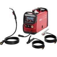
| Product type | Multifunction welding machine MIG/MAG, TIG, MMA |
| Brand | Stamos |
| Model | S-MTM 220 |
| Input voltage | 230 V ~ 50 Hz single-phase |
| MIG current range | 30 - 220 A |
| TIG current range | 10 - 220 A |
| MMA current range | 10 - 220 A |
| Open circuit voltage | 59 V |
| MIG duty cycle | 60 % at 220 A, 100 % at 170 A |
| TIG duty cycle | 60 % at 220 A, 100 % at 170 A |
| MMA duty cycle | 60 % at 220 A, 100 % at 170 A |
| Efficiency | 93 % (MOSFET technology) |
| Shielding gas | Argon (for TIG) |
| Gasless welding | Possible with flux-cored wire (reverse polarity) |
| Protection class | IP21 |
| Cooling | Fans |
| Technology | MOSFET |
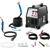
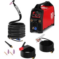
| Supplied accessories | Ground cable, electrode holder, TIG torch WP-26 (nozzles no. 5/6/7, collets 1.6/2.4/3.2 mm, tungsten electrode), MIG torch MB15AK (contact tips 0.8/0.9 mm), welding helmet, slag hammer, wire brush |
| Maintenance | Regularly check cables and connections, clean ventilation openings |
| Safety | Thermal overload protection, fault/overload indicator, many safety instructions (helmet, gloves, clothing, avoid damp contact) |
| Repairability | Spare parts available from the manufacturer |
Frequently Asked Questions - S-MTM 220 Stamos
User questions about S-MTM 220 Stamos
0 question about this device. Answer the ones you know or ask your own.
Ask a new question about this device
Download the instructions for your Welding machine in PDF format for free! Find your manual S-MTM 220 - Stamos and take your electronic device back in hand. On this page are published all the documents necessary for the use of your device. S-MTM 220 by Stamos.
USER MANUAL S-MTM 220 Stamos
Rev. 06.05.2022 Rev. 06.05.2022
WIG:
If you have doubts on connecting and operating with this device, please contact the manufacturer. The user must read this manual carefully before first use of the device.
MIG/MAG
The welding equipment for manual arc welding with automatic wire feed allows the joining of metal parts through a melting process of the edges to be joined and the filler metal. Melting is caused by the arc, which is formed between the material to be welded and the metal wire continuously emerging from the end of the burner. Metal wire serves as a filler material for the connection of the parts. Higher welding current allows welding of bigger plates. For damages resulting from failure to comply with these instructions, no liability is accepted.
The tungsten inert gas welding technology (TIG welding) comes from the U.S., where it became known in 1936 as argon welding. Only after the second World War II was it introduced in Germany. In English-speaking countries this method is called TIG, after the English word for tungsten. The method offers several interesting advantages over other fusion welding processes. For example, it is universally applicable: if a metallic material is at all suitable for welding, then it can be processed with this procedure. Additionally it is also a very „clean“ process, which produces very little pollution and little splashes and, when used correctly, guarantees a high quality welded joint. A particular advantage of TIG welding is also the fact that compared to other methods employing a consumable electrode, the addition of a filler material and the current are not linked.
Therefore the welder has control over the power:
- it may be optimally matched to the welding task and it is only necessary to add as much filler as is currently required. This makes the process particularly suitable for welding root passes and for welding in forced positions.
- due to the relatively low and small-scale heat input there is little tendency for the workpieces to warp during welding.
• these advantages have caused the process to be particularly suitable for welding of air planes and space vehicles, construction elements used in nuclear installations and installation components and equipment for chemical plants.
MMA
MANUAL ARC WELDING
Manual arc welding, briefly called MMA (Manual Metal Arc Welding), is one of the oldest electric welding procedures used for metallic materials, which is still used today. In 1891 Nikolai Gavrilovich Slawjanow replaced the carbon electrodes commonly used in his time for arc welding by a metal rod that was both the arc carrier and filler metal. Since the first rod electrodes were not coated, the weld itself was not protected from oxidation. Therefore these electrodes were difficult to weld. The electric arc burning between an electrode and the workpiece is used as the heat source for welding.
The high temperature of the arc melts the material in the welding area. The rod electrode simultaneously melts off acting as a filler material to form the weld bead. Both AC and DC currents can be used to power the process. Rod electrodes are used as filler material in arc welding. For each welding type there are appropriate electrodes, e.g. for build-up welding and joint welding. Information concerning the nature, characteristics and application of an electrode is provided by the brief label, which is printed on each electrode package. The gases produced by the melting of the electrode coating are used to stabilise the arc and separate the liquid metal transfer in the arc from the influences of the surrounding air and to reduce the burning of alloy components. Apart from that the melted coating also produces slag. This liquid is lighter than liquid steel and is washed onto the weld. This enables a slow cooling process and thus lower shrinkage stress. The anode (positive pole) is heated by electron bombardment and positive metal ions flow from there to the workpiece. Therefore consumable electrodes are mostly used as anodes with the workpiece material acting as a negative pole. In TIG welding the electrode has a negative pole in order to keep the degree of removal low. Arc welding is used in the construction industry (bridge supports) but also in precision engineering. The following rule applies regardless of application: The thinner the material, the more expensive the equipment. Due to low current levels (necessary not to burn through materials under 1 mm wall thickness), a significantly more complex control process is required.
GENERAL SAFETY
If you have doubts on connecting and operating with this device, please contact the manufacturer. The user must read this manual carefully before first use of the device.
DUTY CYCLE
Duty cycle is a welding equipment specification which defines the number of minutes, within a 10 minute period, during which a given welder can safely produce a particular welding current. For example, a 200 amp welder with a 60% duty cycle must be „rested“ for at least 4 minutes after 6 minutes of continuous welding with 200 amp..
WORK AREA PRECAUTIONS
- Keep your work area clean and well lit. Cluttered benches and dark areas invite accidents.
- Do not operate power tools in explosive atmospheres, such as in the presence of flammable liquids, gases, or dust. Power tools create sparks which may ignite the dust or fumes.
- Keep bystanders, children, and visitors away while operating a power tool. Dis-tractions can cause you to lose control. Protect others in the work area from debris such as chips and sparks. Provide barriers or shields as needed.
EN
EN
ELECTRICAL SAFETY
- Grounded tools must be plugged into an outlet properly installed and grounded in accordance with all codes and ordinances. Never remove the grounding prong or modify the plug in any way. Do not use any adapter plugs. Check with a qualified electrician if you are in doubt whether the outlet is properly grounded. If the tool should electrically malfunction or break down, grounding provides a low resistance path to carry electricity away from the user.
- Double insulated tools are equipped with a polarized plug (one blade is wi der than the other). This plug will fit in a polarized outlet only one way. If the plug does not fit fully in the outlet, reverse the plug. If it still does not fit, contact a qualified electrician to install a polarized outlet. Do not change the plug in any way. Double insulation eliminates the need for the three wire grounded power cord and grounded power supply system.
- Avoid body contact with grounded surfaces such as pipes, radiators, ranges, and refrigerators. There is an increased risk of electric shock if your body is grounded.
- Do not expose power tools to rain or wet conditions. Water entering a power tool will increase the risk of electric shock.
- Do not abuse the Power Cord. Never use the Power Cord to carry the tool or pull the Plug from an outlet. Keep the Power Cord away from heat, oil, sharp edges, or moving parts. Replace damaged Power Cords immediately. Damaged Power Cords increase the risk of electric shock.
- When operating a power tool outside, sue an outdoor extension cord mar- ker "WA" or "W". These extension cords are rated for outdoor use, and reduce the risk of electric shock.
PERSONAL SAFETY
- Stay alert. Watch what you are doing, and use common sense when operating a power tool. Do not use a power tool while tired or under the influence of drugs, alcohol, or medication. A moment of inattention while operating power tools may result in serious personal injury.
- Dress properly. Do not wear loose clothing or jewelry. Contain long hair. Keep your hair, clothing, and gloves away from moving parts. Loose clothes, jewelry, or long hair can be caught in moving parts.
- Avoid accidental staring. Be sure the Power Switch is off before plugging in. Carrying power tools with your finger on the Power Switch, or plugging in power tools with the Power Switch on, invites accidents.
- Remove adjusting keys or wrenches before turning the power tool on. A wrench or a key that is left attached to a rotating part of the power tool may result in personal injury.
- Do not overreach. Keep proper footing and balance at all times. Proper footing and balance enables better control of the power tool in unexpected situations.
- Use safety equipment. Always wear eye protection. Dust mask, non-skid safety shoes, hard hat, or hearing protection must be used for appropriate conditions.
TOOL USE AND CARE
- Use clamps (not included) or other practical ways to secure and support the workpiece to a stable platform. Holding the work piece by hand ro against your body is unstable and may lead to loss of control.
- Do not force the tool. Use the correct tool for your application. The correct tool will do the job better and safer at the rate for which it is designed.
- Do not use the power tool if the Power Switch does not turn it on or off. Any tool that cannot be controlled with the Power Switch is dangerous and must be replaced.
- Disconnect the Power Cord Plug from the power source before making any adjustments, changing accessories, or storing the tool. Such preventive safety measures reduce the risk of starting the tool accidentally.
- Store idle tools out of reach of children and other untrained persons. Tools are dangerous in the hands of untrained users.
- Maintain tools with care. Keep cutting tools maintained and clean. Properly maintained tools are less likely to bind and are easier to control. Do not use a damaged tool. Tag damaged tools "Do not use" until repaired
- Check for misalignment or binding of moving parts, breakage of parts, and any other condition that may affect the tool's operation. If damaged, have the tool serviced before using. Many accidents are caused by poorly maintained tools.
- Use only accessories that are recommended by the manufacturer for your model. Accessories that may be suitable for one tool may become hazardous when used on another tool.
SERVICE
- Tool service must be performed only by qualified repair personnel. Service or maintenance performed by unqualified personnel could result in a risk of injury.
- When servicing a tool, use only identical replacement parts. Use of unauthorized parts or failure to follow maintenance instructions may create a risk of electric shock or injury.
SPECIFIC SAFETY RULES
I. Maintain labels and nameplates on the tool. These carry important information. If unreadable or missing, contact our service team for a replacement.
2. Always wear the approved safety impact eye goggles and heavy work gloves when suing the tool. Using personal safety devices reduce the risk for injury. Safety impact eye goggles and heavy work gloves are available from Harbor Freight Tools.
3. Maintain a safe working environment. Keep the work area well lit. Make sure there is adequate surrounding workspace. Always keep the work area free of obstructions, grease, oil, trash, and other debris. Do not use a power tool in areas near flammable chemicals, dusts, and vapors. Do not use this product in a damp or wet location.
4. Avoid unintentional starting. Make sure you are prepared to begin work before turning on the tool.
EN
EN
- Never leave the tool unattended when it is plugged into an electrical outlet. Turn off the tool, and unplug it from its electrical outlet before leaving.
- Always unplug the tool from its electrical outlet before performing and inspection, maintenance, or cleaning procedures.
- Prevent eye injury and burns. Wearing and using the approved personal safety clothing and safety devices reduce the risk for injury.
a. Wear the approved safety impact eye goggles with a welding helmet fea- turing at least a number 10 shade lens rating.
b. Leather leggings, fire resistant shoes or boots should be worn when using this product. Do not wear pants with cuffs, shirts with open pockets, or any clothing that can catch and hold molten metal or sparks.
c. Keep clothing free of grease, oil, solvents, or any flammable substances. Wear dry, insulating gloves and protective clothing.
d. Wear an approved head covering to protect the head and neck. Use aprons, cape, sleeves, shoulder covers, and bibs designed and approved for welding and cutting procedures.
e. When welding/cutting overhead or in confined spaces, wear flame resistant ear plugs or ear muffs to keep sparks out of ears.
- Prevent accidental fires. Remove any combustible material from the work area. a. When possible, move the work to a location well away from combustible protect the combustibles with a cover made of fire resistant material.
b. Remove or make safe all combustible materials for a radius of 35 feet (10 meters) around the work area. Use a fire resistant material to cover or block all open doorways, windows, cracks, and other openings.
c. Enclose the work area with portable fire resistant screens. Protect combustible walls, ceilings, floors, etc., from sparks and heat with fire resistant covers. d. If working on a metal wall, ceiling, etc., prevent ignition of combustibles on the other side by mobbing the combustibles to a safe location. If relocation of combustibles is not possible, designate someone to serve as a fire watch, equipped with a fire extinguisher, during the welding process and for at least one half hour after the welding is completed.
e. Do not weld or cut on materials having a combustible coating or combustible internal structure, as in walls or ceilings, without an approved method for eliminating the hazard.
f. Do not dispose of hot slag in containers holding combustible materials.
g. After welding or cutting, make a thorough examination for evidence of fire. Be aware that easily visible smoke or flame may not be present for some time after the fire has started. Do not weld or cut in atmospheres containing h. Dangerously reactive or flammable gases, vapors, liquids, and dust.
i. Provide adequate ventilation in work areas to prevent accumulation of flammable gases, vapors, and dust. Do not apply heat to a container that has held an unknown substance or a combustible material whose contents, when heated, can produce flammable or explosive vapors. Clean and purge containers before applying heat. Vent closed containers., including castings, before preheating, welding, or cutting.
WARNING
INHALATION HAZARD: WELDING AND PLASMA CUTTING PRODU-CE TOXIC FUMES.
Exposure to welding or cutting exhaust fumes can increase the risk of developing certain cancers, such as cancer of the larynx and lung cancer. Also, some diseases that may be linked to exposure to welding or plasma cutting exhaust fumes are:
a. Early onset of Parkinson's Disease
b. Heart disease
c. Ulcers
d. Damage to the reproductive organs
e. Inflammation of the small intestine or stomach
f. Kidney damage
g. Respiratory diseases such as emphysema, bronchitis, or pneumonia
Use natural or forced air ventilation and wear a respirator approved by NIOSH to protect against the fumes produced to reduce the risk of developing the above illnesses.
-
Avoid overexposure to fumes and gases. Always keep your head out of the fumes. Do not breathe the fumes. Use enough ventilation or exhaust, or both, to keep fumes and gases from your breathing zone and general area.
-
Where ventilation is questionable, have a qualified technician take an air sampling to determine the need for corrective measures. Use mechanical ventilation to improve air quality. If engineering controls are not feasible, use an approved respirator.
• Work in a confined area only if it is well ventilated, or while wearing an airsupplied respirator. - Follow OSHA guidelines for Permissible Exposure Limits (PEL's) for various fumes and gases.
- Follow the American Conference of Governmental Industrial Hygienists recommendations for Threshold Limit Values (TLV's) for fumes and gases.
- Have a recognized specialist in Industrial Hygiene or Environmental Services check the operation and air quality and make recommendations for the specific welding or cutting situation.
- Always keep hoses away from welding/cutting spot. Examine all hoses and cables for cuts, burns, or worn areas before each use. If any damaged areas are found, replace the hoses or cables immediately.
- Read and understand all instructions and safety precautions as outlined in the manufacturer's Manual for the material you will weld or cut.
- Proper cylinder care. Secure cylinders to a cart, wall, or post, to prevent them from falling. All cylinders should be used and stored in an upright position. Never drop or strike a cylinder. Do not use cylinders that have been dented. Cylinder caps should be used when moving or storing cylinders. Empty cylinders should be kept in specified areas and clearly marked "empty."
- Never use oil or grease on any inlet connector, outlet connector, or cylinder valves.
EN
- Use only supplied Torch on this Inverter Air Plasma Cutter. Using components from other systems may cause personal injury and damage components within.
- People with pacemakers should consult their physician(s) before using this product. Electromagnetic fields in close proximity to a heart pacemaker could cause interference to, or failure of the pacemaker.
- USE PROPER EXTENSION CORD. Make sure your extension cord is in good condition. When using an extension cord, be sure to sue one heavy enough to carry the current your product will draw. An undersized cord will cause a drop in line voltage resulting in loss of power and overheating. A 50 foot extension cord must be at least 12 gauges in diameter, and a 100 foot extension cord must be at least 10 gauges in diameter. If in doubt, use the next heavier gauge. The smaller the gauge number, the heavier the cord.
CHECKING PACKAGING UPON CONSIGNMENT
When you received the goods proceed with opening the packaging if there are no signs of damage. If there are signs of damage on packaging please send a detailed list and report of all damage to the goods to your local representative within 3 days after delivering.
Disposing of packaging
The various items used for packaging (cardboard, plastic straps, polyurethane foam) should be conserved, so that the device can be sent back to the service centre in best conditions in case of problem.
SETTING THE DEVICE
Setting the welder must be carried out in accordance with the following rules:
- The operator must have free access to the device as well as its connections and controls.
- It is forbidden to set the device in small rooms. It is important that the room must be equipped with good ventilation system, it should be clean and without dust.
- The device with wiring can not be obstacle on the passage and can not reduce the work area of other workers.
- The device can be placed only on a flat surface. The gas cylinders must be properly protected.
SUPPLIED EQUIPMENT:
Cable with mass clamp.
MMA welding cable with electrode holder.
TIG welding cable WP-26 along with accessories:
Collets: 1.6 mm / 2.4 mm / 3.2 mm.
Ceramic nozzles no 5, 6, 7.
Long cap.
Tungsten.
MIG welding cable MB15AK along with contact tips 0.8 mm and 0.9 mm.
Gas hose.
Mask.
Hammer.
Brush.
EN


CERTIFICATES –welder has been manufactured in accordance with CE and RoHS certificates. It guarantees long life time and high quality of the device.
The welder uses MOSFET technology. This technology (as no other) ensures the highest efficiency. In comparison to the current consumption amount we gather over-proportional power amount. This results in the efficiency of 93%! Welding current is very stable and it ensures perfect fusion weld. Thanks to the MOSFET technology, the machine is light and compact.

Standard supply voltage = the welder is supplied by 230 V voltage from the single-phase socket (230V +/- 10%).

INERT GAS = for WIG / TIG welding it is necessary to use inert gas (e.g. argon).

FANS = very efficient fans ensure the optimal heat release during the welder operation.
INSTALLATION AND CONNECTION
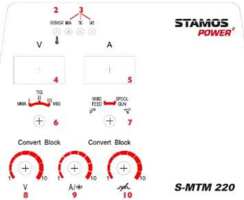
User panel:


EN
EN
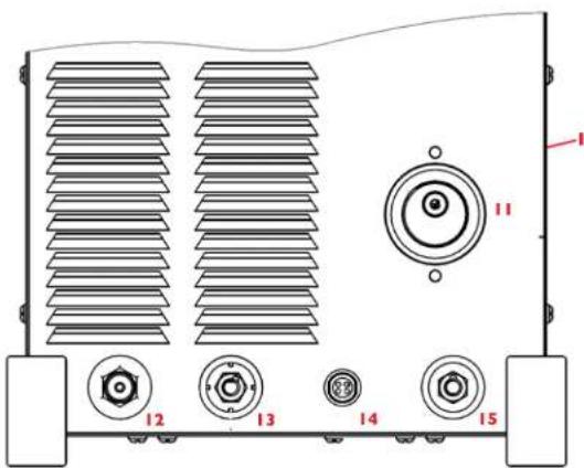
| No. | Description |
| 1. | Main switch (at the back of the device) |
| 2. | Overloading / failure |
| 3. | Power and working state indicator (MMA,TIG,MIG) |
| 4. | Welding voltage (V) |
| 5. | Welding current (A) |
| 6. | The working state of welding machine selection (MMA,TIG,MIG) |
| 7. | Welding torch (push wire and pull wire) selection |
| 8. | Welding voltage adjustment: When welding, it is used for the regulating the welding voltage. It is valid in the MIG welding state, but it's invalid in the TIG and MMA welding state. |
| 9. | Welding current adjustment: TIG / MMA. Feed wire speed: MIG welding state. |
| 10. | Arc welding feature adjustment – inductance adjustment – only MIG welding state |
| 11. | Welding torch EURO type socket. |
| 12. | Integrated gas-electric output: connect with the TIG welding torch (polarity -) |
| 13. | Quick connector socket: welding machine output (-) |
| 14. | Four core socket: It is used for controlling the output of welding machine – TIG or spool gun |
| 15. | Quick connector socket: welding machine output (+) |
CONNECTION DIAGRAM
MIG/MAG:
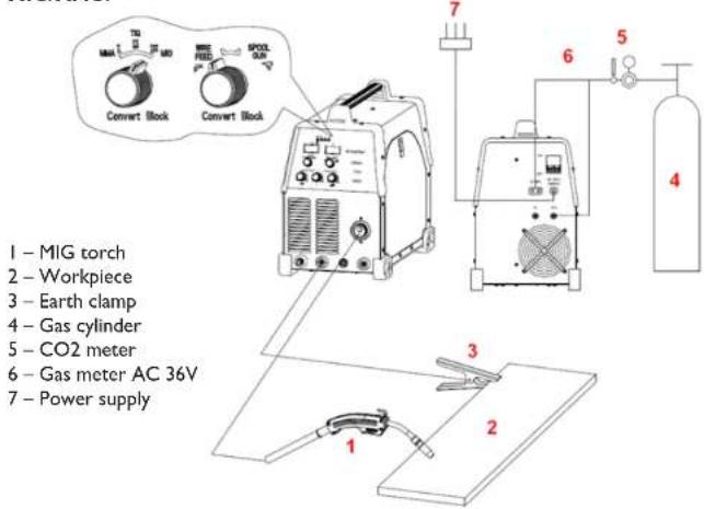
FLUX (FCAW (Flux-Cored Arc Welding)):
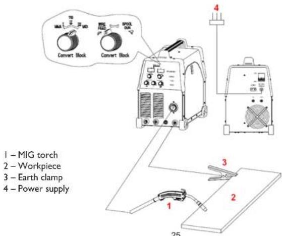
EN
EN
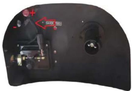
NOTE: FLUX (FCAW (Flux-Cored Arc Welding)) requires a change of the polarization inside the welder. Picture below is showing standard connection when using MIG/MAG welding with solid wire. In order to use the device for welding with FLUX wire, the connection should be swapped, connecting the cable to the clamp marked with (-):
MIG/MAG WITH USING THE SPOOL GUN:
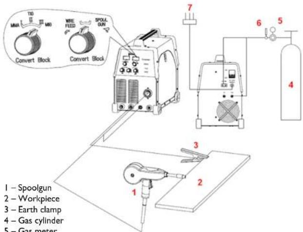
I - Spoolgun
2 - Workpiece
3 - Earth clamp
4 - Gas cylinder
5 - Gas meter
6 - Gas meter AC 36V
7 - Power supply
26
Rev. 06.05.2022 Rev. 06.05.2022
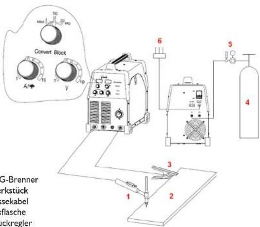
TIG WELDING:
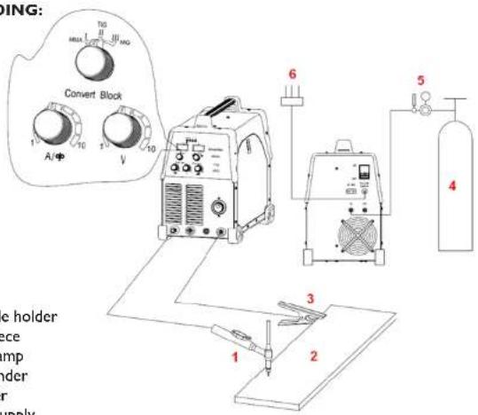
I - Electrode holder
2 - Workpiece
3 - Earth clamp
4 - Gas cylinder
5 - Ar meter
6 - Power supply
MMA WELDING:
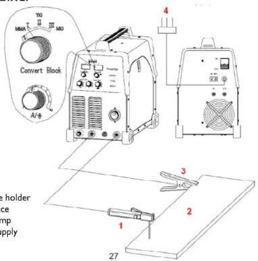
I - Electrode holder
2 - Workpiece
3 - Earth clamp
4 - Power supply
EN
EN
TECHNICAL DATA
| Model S-MTM 220 | ||
| Rated Input Voltage 230V | ||
| No-Load Loss 50W | ||
| Efficiency 0.8 | ||
| Power Factor 0.73 | ||
| No-load output voltage 59V | ||
| MIG Rated Input Current 31.5 | ||
| Output Voltage adjustment Range 14-25 | ||
| Output Current Range 30-220 | ||
| Load Duty Cycle | ||
| Current for the Load Duty Cycle 100% | ||
| TIG | Rated Input Current 23.7 | |
| Output Current Range 10-220 | ||
| Load Duty Cycle | 60% | |
| Current for the Load Duty Cycle 100% | 170 | |
| MMA | Rated Input Current 36.3 | |
| Output Current Range 10-220 | ||
| Load Duty Cycle | 60% | |
| Current for the Load Duty Cycle 100% | 170 | |
| Protection Class | IP21 | |
| Cooling method | ventilator | |
The TIG-welding is very sensitive about the surface (which is to be welded) contamination. For this reason, before welding you have to remove rests of paints and greases as well as the oxidized layer from the surface which will be welded.
DCTIG-welding
- Connect the gas hose to the gas to welder supply socket.
- Connect the gas hose to the welding gun and to the argon supply (to the gun) socket.
- Connect weld piece to the mass clamp in welder, outlet (+).
- Connect the welding handle plug to the arc and argon control rod.
Gas test: Check the connection of the electric supply and switch on the voltage.
Open the valve (regulator) of bottle with argon and switch on flow meter. Gun switch-key has to be pressed and you have to select an appropriate gas flow. The inflow switch-key has to be released and the gas inflow
2829
Rev. 06.05.2022 Rev. 06.05.2022
will be automatically stopped after several seconds. In case of using the high frequency ignition, the wolframic electrode has to be retracted 2-3 mm from the weld piece. Next, after switching on the switch-key, the arc will be triggered. The switch off will result in the reduction of electric current intensity and the arc will no longer be active. The blowing shaft can not decay before the electric arc switch off. Gas must cool down the fusion weld as it will not become oxidized. After finishing the welding process, you have to switch off the argon supply button on the bottle and the welder supply. Pulling the electric supply plug when the electric supply switch is on is prohibited.
Manual welding with the electrode
- Connect the E-Hand conduit to the negative pole (-).
- Set the current intensity regulator at the proper intensity (the impulse current intensity regulator is in lower position). Select current in accordance with empirical formula: l = 40d , where d is the electrode diameter.
• Positive and negative connection during the welding process. - The welder has to be connected to the electric supply socket and turn main switch on. The control lamp will light.
- It is necessary to bring the attention to the relative intensity of welding current and the relative welder's make-time.
• The overloading may result in damages. You can avoid this. - After finishing the device operation, it is necessary to leave the device for cooling and then – switch off the supply.
MIG/MAG welding
Please install the items in the order shown. Pay attention to the proper arrangement of the elements as shown in the pictures. The device is not operational yet. Open the gas flow at a pressure of 5-7 l/min. Protect the gas outlet against gusts of wind. Also note the following: The first stages of the current controller are used for welding thin metal sheets and the next stages are used for thicker walls. With each operation of the switch the wire feed speed should also be adjusted. If a drop is formed at the end of the welding wire while welding, the wire feed speed has to be increased; however if it can be felt as the wire presses against the hose bundle, the speed has to be reduced. Always use tongs to move the parts that have just been welded and to remove encrustations at the end of the burner, as these elements are very hot. Once the arc is ignited keep the hose bundle at an angle of about 30 degrees vertically.
WEEKLY MAINTENANCE
Check if the room ventilation works properly.
CZ
CZ
NÁVOD K OBSLUZE
VŠEOBECNÉ BEZPEČNOSTNÍ POKYNY
3839
Rev. 06.05.2022 Rev. 06.05.2022
Rev. 06.05.2022 Rev. 06.05.2022
TECHNICKÉ ÚDAJE
Sans raccord de gaz (FLUX) (FCAW (Flux-Cored Arc Welding)) :

Rev. 06.05.2022 Rev. 06.05.2022
FR
FR
DÉTAILS TECHNIQUES
6465
Rev. 06.05.2022 Rev. 06.05.2022
Rev. 06.05.2022 Rev. 06.05.2022
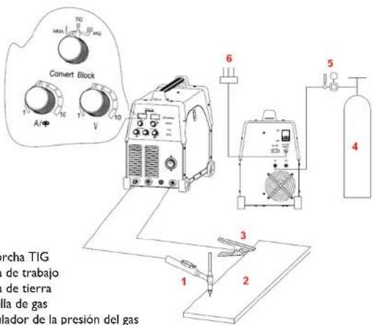
WIG:
For the disposal of the device please consider and act according to the national and local rules and regulations.
CONTACT
expondo Polska sp. z o.o. sp. k.
- MIG/MAG
- MMA
- MANUAL ARC WELDING
- GENERAL SAFETY
- DUTY CYCLE
- WORK AREA PRECAUTIONS
- EN
- ELECTRICAL SAFETY
- PERSONAL SAFETY
- TOOL USE AND CARE
- SERVICE
- SPECIFIC SAFETY RULES
- WARNING
- INHALATION HAZARD: WELDING AND PLASMA CUTTING PRODU-CE TOXIC FUMES
- CHECKING PACKAGING UPON CONSIGNMENT
- DISPOSING OF PACKAGING
- SETTING THE DEVICE
- SUPPLIED EQUIPMENT
- INSTALLATION AND CONNECTION
- 26
- DCTIG-WELDING
- MANUAL WELDING WITH THE ELECTRODE
- MIG/MAG WELDING
- WEEKLY MAINTENANCE
- CZ
- NÁVOD K OBSLUZE
- VŠEOBECNÉ BEZPEČNOSTNÍ POKYNY
- CONTACT
Brand : Stamos
Model : S-MTM 220
Category : Welding machine