VDV-907 - Intercom m-e - Free user manual and instructions
Find the device manual for free VDV-907 m-e in PDF.


User questions about VDV-907 m-e
0 question about this device. Answer the ones you know or ask your own.
Ask a new question about this device
Download the instructions for your Intercom in PDF format for free! Find your manual VDV-907 - m-e and take your electronic device back in hand. On this page are published all the documents necessary for the use of your device. VDV-907 by m-e.
USER MANUAL VDV-907 m-e
User Interface in talk mode 35
User Interface Settings 36
SCOPE OF DELIVERY 37
LEGEND 37
User interlace (UI) 38
INSTALLATION (FIG. 2A+B) 38
COMMISSIONING 39
Power supply connection 39
INSERTING MICROSDCARDS39
INITIALISATION /RESET 40
OPERATION 40
BASIC FUNCTIONS 40
Ringing 40
Standby mode 40
Door release button (sensor touch) 40
Mute key (sensortouch) 40
Activate screen 41
ADVANCED FUNCTIONS 41
Light 41
Arrow symbol Right and Left 41
Alarm symbol 41
Volume + and 41
Murekey 61
Carmera button 41
PICTURE MEMORY AND SETTINGS 42
Switching on the screen 42
Changing the name of the outdoor unit: 42
Switching between outdoor units 42
Picture memory 42
Settings 12
Setting the language 43
Setting the basic volume (B2) 43
Setting the time and date 43
Basic settings 43
Setting the meody 43
Help menu 44
Picture Settings 44
ConnectWLAN 44
Information about the indoor unit 45
Delet ing all pictures 45
Reset 45
Coding the Bell receiver 45
TABLE OF CONTENTS
Setting the melody of the radio chime 45
Coding the CUVEO receiver 49
Changing the coding 46
TECHNICAL DATA 46
NOTES 46
Cleaning and care 46
Legal principles 45
SAFETY NOTES 47
2 YEAR LIMITED GUARANTEE 47
VDV-907 | ENGLISH

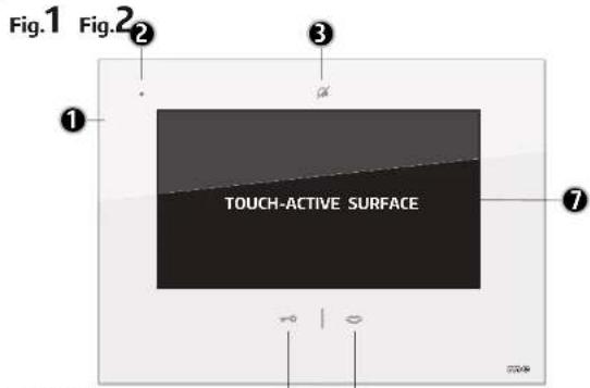
1-VDV907
2=Microphone
3 - Silence button (sensortouch)
4 - Door release button (sensortouch)
5 = Talk button (sensortouch)
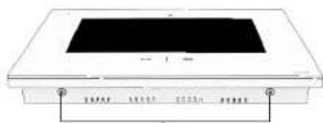
6 = Housing screws
7 = Touch-active surface
B = MicroSD slot 2 photos
9 = MicroSD slot 1 ring tones
6
31
VISTUS
ENGLISH VDV-907
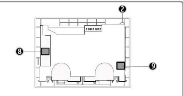
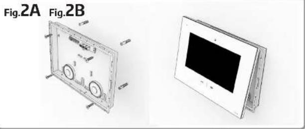
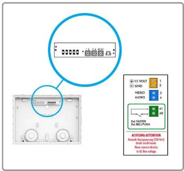
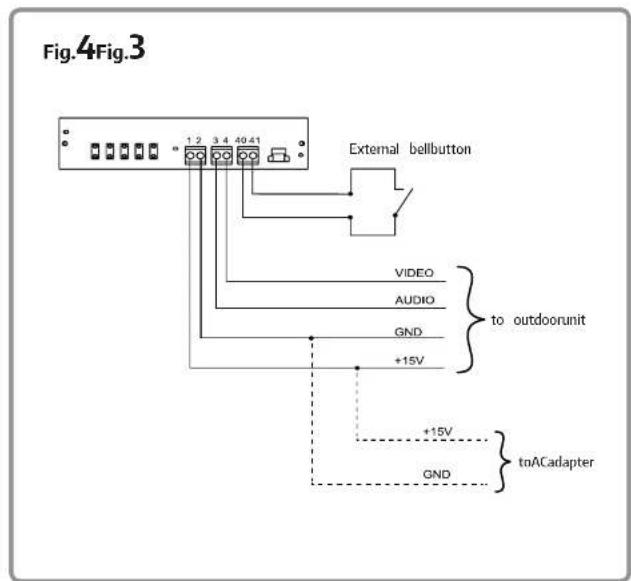
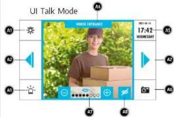
Fig.A USER INTERFACE (UI)
UI Picture Memory and Settings
User Interface in talk mode
A1-Lightkey
A2 - Shift keys
A3 = Alarm key
A4 = Name of outdoor unit
A5 = Time / date display
A6 = Photo button
A7 = Voicevolume
A8=Muteburton
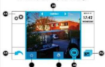
A9 = Change outdoor unit name
A10=Settings
ATI = Back button
A12 - Picture memory key
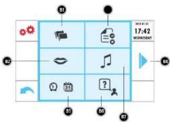
Fig.B
UI Settings Page 1
User Interface Settings
B1 = Language
B2-Speech volume
B3-Time/ date
B4 = Previous page
BS = Basic settings
B6 Next page
B7=Melodyindoorunit
B8
B9 = Picture settings
BIO = WLAN settings
B11 = Information
B12 = Delete all photos
B13 - Factory settings
B14 = Radio chime melody

VDV-907 indoor unit
forvideo door intercom systems
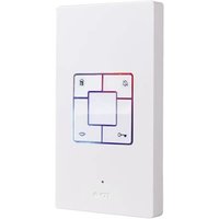
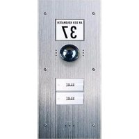
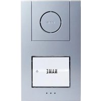
Thank you for purchasing this video indoor unit with integrated picture memory and WIAN function. This indoor unit can be combined with all components from the VISTA-DOOR and VISTUS door intercom systems.
When the bell is rung at the connected outdoor unit, the indoor unit plays the set ringing melody and the visitor can be seen on the monitor. Furthermore, 3 photos are automatically saved.
You can speak to the visitor at the indoor unit and also open the door (if a door opener is connected).
If the VDV-907 is connected via WLAN, a connection to your smartphone can also be established. Atwww.vistasmart.de you will find more information on how to install the app and integrate the VDV-907.
This indoor unit has two card slots for microSD cards (max. 32GB). Audio files can be stored on a microSD card in
slot 1 (8), which can then be used as a ringtone. For the picture storage function, another microSD card is required in slot 2 (9). No memory cards are included in the scope of delivery.
SCOPE OF DELIVERY
- Indoor unit with 7^ screen diagonal
- Mounting material
- Operating and installation instructions
-Drilling template
LEGEND
1-VDV907
2=Microphone
3 - Silence button (sensortouch)
4 = Door release button (sensortouch)
5 = Talk button (sensortouch)
6 = Housing screws
7 = Touch-active surface
B=MicroSD slot 2 photos
9 = MicroSD slot 1 ring tones
User interface(UL)
A1 = Light key
A2 = Shift keys
A3 - Alarm key
A4 = Name of outdoor unit
A5 = Time / date display
A6-Photo button
A7 = Voice volume
A8 = Mute button
A9 = Change outdoor unit name
A10 = Setting
A11 = Back button
A12 = Picture memory key
B1 = Language
B2 = Speech volume
B3 = Time / date
B4 = Previous page
B5 = Basic settings
B6 = Next page
B7-Melodyindoorunit
B8 = Help
B9 = Picture settings
B10 = WLAN settings
B11 = Information
B12 = Delete all photos
B13 = Factory settings
B14 - Radio chime melody
- Find a suitable place to install the indoor unit and run the cables to it.
- Remove the two screws (f6) on the indoor unit and lift off the front cover of the indoor unit.
- There are two plastic retaining lugs in the centre of the sides of the indoor unit. Carefully pull off the front cover.
- There is a hole in the top of the housing below the connection terminals for inserting the cables into the housing.
- You can use the bottom of the housing as a drilling template, align it with a spint level just at the point on the wall where the indoor unit is to be mounted.
- Mark the holes on the wall with a suitable pencil, then drill the holes (0 6 mm) at the marks.
- Insert one of the plugs supplied into each hole.
- Lead the connection cable throughthe hole in the housing base of the indoor unit and screw the housing base to the wall with four screws.
- Connect the cables as shown in the connection diagram (Fig. 4).
NOTE. Do not cut the cables too short. There are lugs in the bottom of the enclosure where the cables can be wound up.
- Place the front cover with the monitor on the edge of the housing base from above and press it down. The latching hooks on the sides must lock into place.
NOTE: Insulate unused cables with insulating tape to avoid short circuits.
- Screwthe front cover back on with the two screws (6).
COMMISSIONING
Powersupplyconnection
The power supply can be connected to either the indoor or outdoor unit. It is also possible to feed in the power supply at a star point, e.g. if all signal lines have been laid from the fuse boxto the outdoor and indoor units. The power supply must then be connected in parallel with groundGND and +15VAfter all components have been mounted and
connected, switch on the operating voltage. Depending on the type of installation, plug the power supply unit into a suitable socket or switch on the circuit breakerto which the DIN rail power supply unit is connected.
INSERTING MICROSDCARDS
Open the indoor unit and carefully place it with the monitor facing downwards on a soft cloth to avoid scratching the glass. Slide the microSD cards into the corresponding slots, with the contact surfaces off the microSD cards facing the circuit board. The slots are equipped with a spring-loaded mechanism that works like a biro. Push the card into the slot until you hear a soft click and the card is locked in place. To remove the cards, gently press them into the card slot and then slowly reduce the pressure. Be careful that the microSD cards do not fly out of the slot due to the spring pressure.
INITIALISATION/RESET
To initialise the system, you must ring once at the outdoor unit (if there are several outdoor units, you must ring once at each outdoor unit). For a reset, disconnect the power supply for approx. 1 minute and then carry out the initialisation again.
NOTE: Before carrying out any work on the system, switch off the operating voltage again! Each time the unit has been without power, the initialisation must be carried out again.
OPERATION
BASIC FUNCTIONS
(TOUCH keys outside the display)
Ringing
Press the bell button of the outdoor unit. The indoor unit plays a ring tone. If a radio chime has been taught-in, it also plays a melody. For more information, read the section 'Programming the BELL receiver'. The indoor unit also saves 3 photos in quick
succession if a microSD card is inserted in card slot 2.
Talk button (sensortouch)
Touch the talk key to activate voice transmission.
Standby mode
If you touch the talk button while the call is active, the indoor unit switches back to standby mode.
Door release button (sensor touch)
Touch the door release button during the call to activate the door opener (if connected).
Mute key (sensortouch)
Touch the mute keyto mute the ring tone. The symbol rights up permanently in red or flashes as long as muting is active. To unmute the ringtone, touch the mute button again.
NOTE: While the mute function is active, the radio signal to a remote-controlled radio chime is not deactivated, i.e. it continues to ring. Mute the BELL receivers if necessary.
Activate screen
Touching the Talk button in standby activates the screen and the voice connection, and the live picture of the outdoor unit is also displayed.
ADVANCED FUNCTIONS
(TOUCH buttons on the screen when ringing or the talk button has been pressed)
Light
Using this button, a receiverfrom the CUVEDO series can be used to switch a light, for example. For more information, see 'Teaching the CUVEDO receiver'.

Arrowsymbol Right and Left
If a second outdoor unit or an additional camera is connected in parallel, the two buttons can be used to switch to the next or previous outdoor unit/camera.
Alarm symbol
If this button is touched during an active call, an alarm signal sounds at the outdoor unit. Touching the button again or ending the call deactivates the alarm tone.
Volume + and -
Touching the ^+ button increases the speech volume, touching the ^- button decreases the speech volume.


NOTE: This setting is only temporary and is reset to the basic volume after the call is ended (see Basic volume setting).

Mute key
If the mute button is pressed during the call, the microphone of the indoor unit is deactivated and the visitor can no longer hearyou. To be able to speak with the visitor again, touch the button once more. If no mute button is displayed, it has been deactivated in the settings menu.

Camera button
If a microSD card for photos is inserted in the indoor unit, a photo can be saved via this button at any time while the picture is active. To do this, simply tap this symbol.

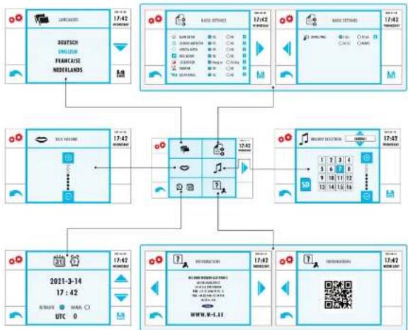
On pages 48 50 you will find an overview of the structure of the OSD (On Screen Display).

Switching on the screen
If the indoor unit is in standby, you can switch it on by touching the black screen area. The camera picture is then displayed, the voice connection to the outdoor unit is not activated here, but the sound from the outdoor unit can be heard.
Once the screen has been activated, the image memory (onlyif an SD card has been inserted), the settings menu and the intercom function are available. Touch the back arrow at the bottom left to switch the indoor unit to standby mode.
Changing the name of the outdoor unit Once the indoor unit has been activated by touching the screen, you can change the name of the outdoor unit to suit your preferences. To do this, simply touch the name of the outdoor unit (AS) and then enter the desired name. Confirm the entered name with the Enter key.
can switch between them by tapping on the arrows next to the name of the outdoor unit.

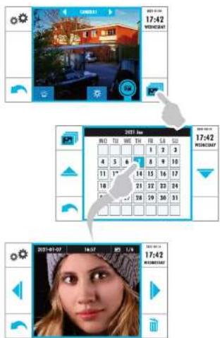
Picture memory
Touch the photo symbol at the bottom right to view the contents of the picture memory on the SD card. The following screen displays a calendar with days on which pictures were taken highlighted in colour: Touch the corresponding dayto view all pictures taken on the selected day. Use the arrow keys to the right and left of the picture to switch to the next or previous picture.

Individual pictures can be deleted by touching the button with the dustbin symbol. The image displayed in each case is deleted without confirmation when the dustbin symbol is touched. If you want to delete all stored pictures at once, see the item "Delete all photos".

Settings
You can access the settings menu if you have switched on the screen bytouching it and then touch the button with the cogwheels.

Setting the language
Touch the flag symbol to access the language selection menu. Touch the desired language there and then save the setting by touching the save symbol. The heading of this menu is immediately displayed in the selected language if the saving was successful. Use the back arrow to return to the settings menu.
Setting the basic volume (B2)
Touch the mouth symbol to set the basic volume. The + button increases the volume, the - button decreases it. The filled dots show you how high the volume is set. The volume is saved automatically. Use the back arrow to return to the settings menu.
Touch the clock/ calendar symbol to enter the settings menu for date and time. Touch the field you want to set (the active field turns blue). You can then use the arrows on the right to change the value. You can set the time and date automatically, which requires a WLAN connection with Internet access, or manually. The UTC (Universal Time, Coordinated) setting should be "0" in manual clock mode.
NOTE: If the time is set to automatic and the UTC is set to 0, the correct time zone is determined automatically. If a different UTC is set, it will always be used. In this case, it is necessary to set the daylight saving time manually. After you have set the date and time, tap the save symbol at the bottom right. You can then exit the menu using the back arrow.

Basic settings
In the basic settings you can determine which control icons should be visible on the main screen and which functions should be active. Tap the info button to the right of each setting to get a description. This settings menu is divided into two pages. You can switch between the pages using the buttons with the arrow (right or left).

NOTE Changes must be saved on each page by trapping the save icon.

Setting the melody
Touch the note symbol to enter the ringtone setting menu. If an SD card with tones stored on it is inserted, the SD card symbol is highlighted in blue and tapping on the "i" plays the first ring tone stored on the SD card. If no
files are stored on the SD card or if no SD card is inserted, the symbol is grey and the internally stored ringstones can be selected automatically via the number field. The volume of the ring tone can be adjusted via the "..." and "..." keys.

NOTE: Audio data in wave or mp3 format can be stored on the microSD card.
It is possible to assign an individual ring tone to each connected outdoor unit. In this way, it is possible to distinguish where the ringing was from the ringing tone. The name offthe outdoor unit forwhich the ring tone is currently set is shown in the upper part of the menu. Use the arrow keys above and below to switch between the outdoor units.

Help menu
Touch the Help button. Here you will find our contact information as well as the QR code for connecting to the app.

Picture Settings
Touch the picture settings icon to adjust the brightness, colour saturation and contrast of the live picture displayed.

Connect WLAN
Tap the WLAN symbol to connect to a nearby WLAN. In the following menu, all nearby WLAN access points are displayed. Tap on yourWLAN and enter the WLAN key. Confirm the key by tapping the Enter key. Wait a short time. If you mistyped the WLAN key, the indoor unit indicates that the connection is not successful and jumps back to the input screen forthe Wlan key and you can check your entry and change it if necessary.
If the indoor unit indicates that the connection is successful, the name of your WLAN is displayed in green at the top.
NOTE: It is not possible to set the network manually. DHCP is always used.
To access the intercom with your smartphone, you need the Vistasmart or Alvisi app. Call up the website https://www.vistasmart.de with your smartphone and select the VDV 907 indoor unit.

On the next page you will find the links to the Android and iOS app, as well as further information on operating the app.

Information about the indoor unit
Touch the information symbol. The operating voltage of the indoor unit is displayed here in volts. It should be between 15V and 15.5V. The IP address of the indoor unit is also displayed.
Deleting all pictures
Touch the dustbin symbol if you want to delete all saved pictures. Touch the green highlighted field there and confirm the following dialogue with 'Old' to delete all pictures or touch 'Cancel' to cancel the deletion process.

RESET Reset
Touch Reset to resetthe indoor unit to factory settings, e.g. if you have forgotten the access data forthe app.
Touch the green button and confirm the reset by tapping OK in the following dialogue. Please note that photos are not deleted by a reset.


Coding the BELL receiver
Tap on the BELL symbol to access the settings menu for the radio chime. Put the receiver into learning mode by pressing the code button until the receiver beeps briefly and then tap one off the letters on the monitor. The receiverplays a melody and is ready to be learned.

Setting the melody of the radio
Tap on the BELL symbol to enter the settings menu forthe radio chime.There you have the option of deactivating the integrated radio module and changing the melody of the radio chime. Tap on a letter, the taught-in radio chime plays the corresponding melody.This melody is immediately saved and you can exit this menu using the back arrow.

Coding the CUVEO receiver
Put the receiver in the learning mode (press the button on the receiver until the LED on the receiverflashes) and activate the monitor by tapping on the touch-active surface, then tap on the light symbol. If the light symbol is not displayed, check whether it is activated in the basic settings (BS).

VISTUS
Changing the coding of the radio protocol (CUVEO and BELL) If the CUVEO receiver and/or the BELL receiver activate for no reason, another transmit- ter in the vicinity could be transmitting the same code. To change the code, proceed as follows: The monitor must be in standby. Hold a finger on the mute button approx. 7 seconds) until the keyand mouth symbols light up.
Then all receivers (CUVEO and BELL) must be released.
TECHNICAL DATA
Operating voltage: 15Volt DC
Power consumption: 270 ± 50mA
Frequency WLAN: 2.4GHz; <100mW
Frequency BELL: 434MHz; <10mW
Temperature range: 0-50°C
Max. humidity: 85%
Screen diagonal: 178mm
Monitor resolution: 1024x600
Dimensions: 220x160x28mm (W x H x D)
NOTES
Exposure to strong static, electric or high frequency fields (discharges, mobile phones, radio equipment, mobile phones, microwaves) may impair the function of the equipment (the appliance).
Cleaning and care
Disconnect mains operated units from the mains (pull out the plug) before cleaning. The surface of the housing can be cleaned with a soft cloth moistened with soapwater. Do not use abrasive cleaners or chemicals. Loosen dust deposits on ventilation slots only with a brush and, if necessary, vacuum with a Hoover. Do not hold the suction nozzle directly against the unit.
Legal principles
- As the operator or user of the video door unit, please observe the regulations and legal principles of your country for the use of surveillance devices with regard to personal rights and data protection.
-
In many countries, video images and/or speech may only be transmitted after a visitor has rung the doorbell.
-
mount the camera in such a way thatthe detection range is limited exclusively to the immediate entrance area.
- The unit has an integrated visitor history. Visitors are archived directly in the unit with their picture, date and time. Use this function in accordance with the relevant country-specific legal regulations applicable at the installation site (obligation to notify / archiving). 5.
- If necessary, draw attention to the existence of the unit in a suitable manner.
The warranty will be null and void in case of damages arising from violations of these operating instructions. We are not liable for consequential damages!
We accept no liability for material damages or injuries arising from inappropriate use or violation of the safety instructions. In such cases all warranty claims are null and void.
For reasons of safety and licensing (CE), unauthorised conversion and/or modification of the product is prohibited. Do not take the product apart!
Do not leave packaging material lying about since plastic foils and pockets and polystyrene parts etc. could be lethal toys for children.
The device is suitable only for dry interior rooms (not bathrooms and other moist places). Do not allow the device to get moist or wet.
Handle the product with care - it is sensitive to bumps, knocks or falls even from low heights.
2 YEAR LIMITED GUARANTEE
Fortwo years afterthe date of purchase, the defect-free condition of the product model and its materials is guaranteed. This guaran tee is only valid when the device is used as intended and is subject to regular maintenance checks. The scope of this guarantee is limited
to the repair or reinstallation of any part of the device, and is only valid if no unauthorised modifications or attempted repairs have been undertaken. Customer statutory rights are not affected by this guarantee.
Please note!
No claim can be made under guarantee in the following circumstances:
- Operational malfunction
- Fault through other radio installation (i.e. mobile operation)
- Unauthorised modifications / actions
Mechanical damage - Moisture damage
No proof of guarantee (purchase receipt)
Claims under warranty will be invalidated in the event of damage caused by non-compliance with the operating instructions. We do not accept any responsibility for consequential damage. No liability will be accepted for material damage or personal injury caused by inappropriate operation or failure to observe the safety instructions. In such cases, the guarantee will be rendered void.
Liabilitylimitation
The manufacturer is not liable for loss or damage of any kind including incidental or consequential damage which is the direct or indirect result of a fault to this product.
These operating instructions are published by
in GbHmodenectrnns
An den Kolonaten 37
2510 Bad Zwischenahrn, Germany
The operating instructions reflect the current technical specifications at time of print. We reserve the right to change the technical or physical specifications.
VDV-907
ENGLISH
VISTA
DOOR
GB
VISTUS
ENGLISH | VDV-907
USER INTERFACE
Structure I
USER INTERFACE
Structure II
49
USER INTERFACE
Structure III
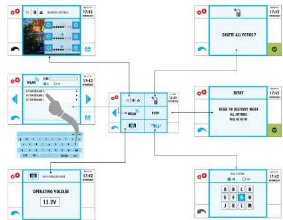
TABLE DES MATIÈRES
FIGURES 55
Interface utiliseu (U) 53
INITIALISATION/RESET 64
FONCTIONNEMENT 64
LES FONCTIONS DE BASE 64
Appeler 64
Bouton de conversation (captur tactile)64
Mode veille 64
B7 = Mélodie station intérieure
B8=Aide
6=Vis de boitier
7 - Surface tactile active
8 = Emplacement microSD 2 (photos)
9 = Emplacement microSD 1 (sonneries)
INITIALISATION/RESET
User Interface: Installingen
B1 = Language
B2-Speech volume
B3-Time date
B4 = Previous page
B5 = Basic settings
B6 = Next page
B7 = Melody indoor unit
B8
B9 = Picture settings
B10 = WLAN settings
B11 = Information
B12 = Delete all photos
B13 - Factory settings
B14 = Radio chime melody
LEVERINGSOMVANG
Binnenstation met 17,8 cm (7") schermdiagonal
- Montagematerialia
- Bedienings-en installment-instructions