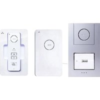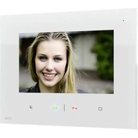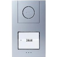
VISTUS AD ALU-410 - Intercom m-e - Free user manual and instructions
Find the device manual for free VISTUS AD ALU-410 m-e in PDF.


User questions about VISTUS AD ALU-410 m-e
0 question about this device. Answer the ones you know or ask your own.
Ask a new question about this device
Download the instructions for your Intercom in PDF format for free! Find your manual VISTUS AD ALU-410 - m-e and take your electronic device back in hand. On this page are published all the documents necessary for the use of your device. VISTUS AD ALU-410 by m-e.
USER MANUAL VISTUS AD ALU-410 m-e
text_image
2 NAME 1 NAME 2 NAME 3 3 6 4 5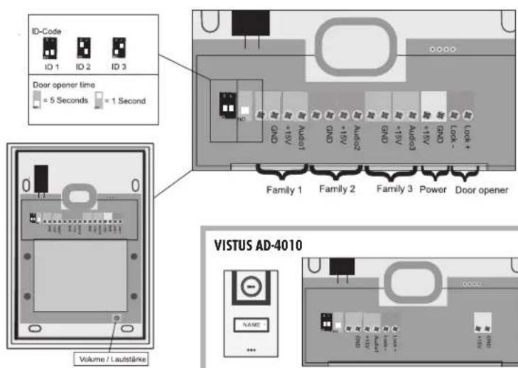
text_image
ID-Code ID 1 ID 2 ID 3 Door opener time = 5 Seconds = 1 Second Family 1 Family 2 Family 3 Power Door opener VISTUS AD-4010 NAME Volume / Lautstärke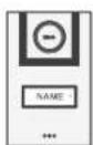
text_image
D20 D21 D22 D23 D24 D25 D26 D27 D28 D29 D30 D31 D32 D33 D34 D35 D36 D37 D38 D39 D40 D41 D42 D43 D44 D45 D46 D47 D48 D49 D50 D51 D52 D53 D54 D55 D56 D57 D58 D59 D60 D61 D62 D63 D64 D65 D66 D67 D68 D69 D70 D71 D72 D73 D74 D75 D76 D77 D78 D79 D80INNENSTATION • INDOOR STATION • BOÎTIER INTÉRIEUR • BINNENSTATION
B
Abb. B
DIAGRAM B
ILLUSTRATION B
AFBEELDING B
text_image
③ ④ ⑤ ⑦ ⑥ ⑮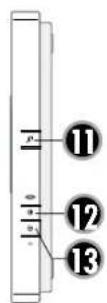
natural_image
Front view of a rectangular electronic device with mounting holes and a central circular component (no text or symbols)INNENSTATION • INDOOR STATION • BOÎTIER INTÉRIEUR • BINNENSTATION
C Abb. C DIAGRAM C ILLUSTRATION C AFBEELDING C
text_image
Bell-Volume Speaker 1 1 +/- GND GND +/- Audio GND +/- Audio +/- GND GND +/- Audio GND +/- Audio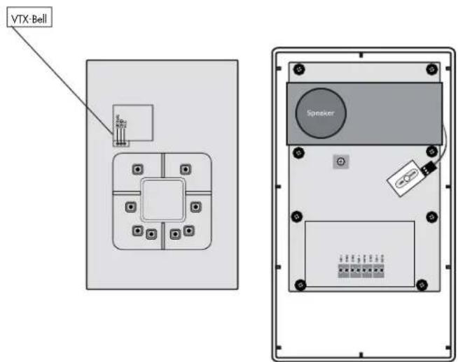
text_image
VTX-Bell SpeakerDE
EINLEITUNG
B. 4= Schlüsseltaste
B. 5=Mikrofon
lips 窗 音 +
B. 6= Sprechtaste
B. 7= Interntaste
B.11= Melodie
B.12= Lautstärke +
B.13= Lautstärke -
VISTUS AD-4020: 71 mm x 25 mm
VISTUS AD-4030: 71 mm x 15mm
ID2 = Schalter 1 "on", Schalter 2 "off"
ID3 = Schalter 1 "off", Schalter 2 "on"
text_image
MIXP NAME 3 NAME 2 NAME 1 ...VISTUS BOOK COMMUNICATION
DEUTSCH | VISTUS AD
natural_image
Simple diagram of a square with internal grid and directional arrows, no text or symbols present.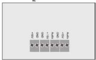
text_image
MAY - MAY + MAY - MAY MAY - MAY MAY - MAY MAY - MAY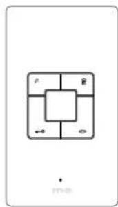
natural_image
Simple diagram of a square with internal grid and directional arrows, no text or symbols present.A
Abb. A
DIAGRAM A
ILLUSTRATION A
AFBEELDING A
AUSSENSTATION • OUTDOOR STATION • BOÎTIER EXTÉRIEUR • BUITENSTATION
text_image
2 NAME 1 NAME 2 NAME 3 3 6 4 5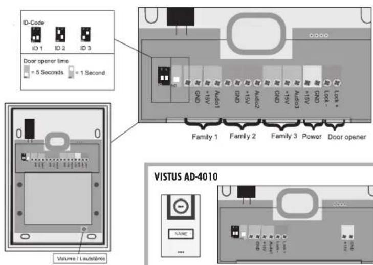
text_image
ID-Code ID 1 ID 2 ID 3 Door opener time = 5 Seconds = 1 Second Family 1 Family 2 Family 3 Power Door opener VISTUS AD-4010 NAME Volume / Lautstärke
text_image
DND USB Audio Line MOSINNENSTATION • INDOOR STATION • BOÎTIER INTÉRIEUR • BINNENSTATION
B
Abb. B
DIAGRAM B
ILLUSTRATION B
AFBEELDING B
text_image
③ ④ ⑤ ⑦ ⑥ ⑮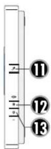
natural_image
Front view of a rectangular electronic device with mounting holes and a central circular component (no text or symbols)INNENSTATION • INDOOR STATION • BOÎTIER INTÉRIEUR • BINNENSTATION
C Abb. C DIAGRAM C ILLUSTRATION C AFBEELDING C
text_image
Bell-Volume Speaker +15V GND GND +15V Audio GND +15V Audio +15V GND GND +15V Audio GND +15V Audio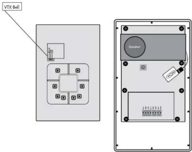
text_image
VTX-Bell SpeakerGB
INTRODUCTION
Thank you for choosing the VISTUS Video intercom system. You have purchased a high quality system.

The assembly should be carried out by a specialist.
Care Information
Wipe the casing with a slightly damp cloth. Do not use aggressive cleaning materials.
Legend
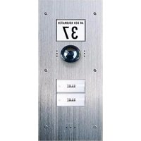
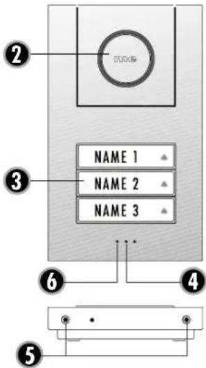
Outdoor station
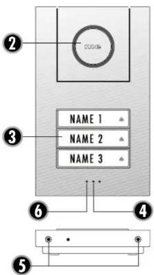
A.2= Loudspeaker
A.3= Nameplates /Bell button
A.4= Microphone
A.5=Casing screws
A.6= Brightness sensor
∅
lips 窗 music + - -
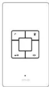
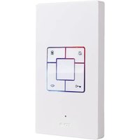
Indoor station
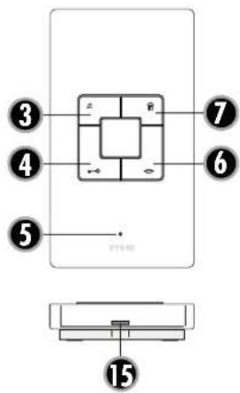
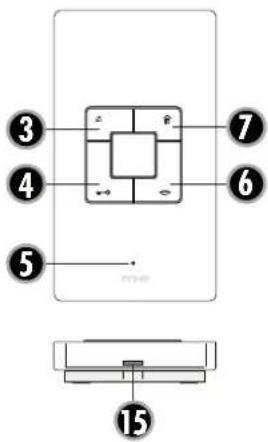
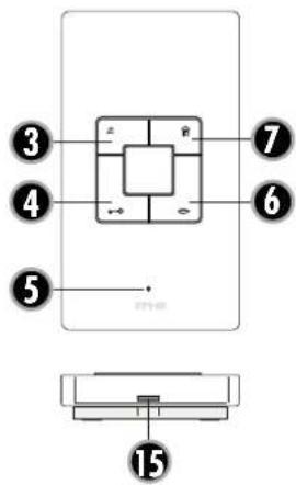
B. 3=Mute button
B. 4= Key button
B. 5= Microphone
B. 6 = Talk button
B. 7= Internal button
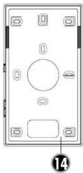
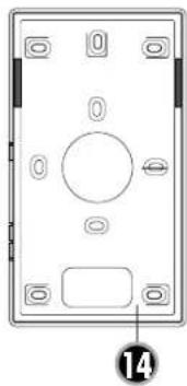
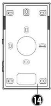
B.14=Casing back
B.15= Snap fastener
C.1 = PCB screws
♪ ⊕ -
B.11= Melody
B.12= Volume +
B.13=Volume -
Scope of delivery VISTUS AD-4010
1x Outdoor station with one bell button
1x Indoor station
1x Power supply ST-1000
1x Assembly materials
Scope of delivery VISTUS AD-4020
1x Outdoor station with two bell buttons
2x Indoor station
1x Power supply ST-1000
1x Assembly materials
Scope of delivery VISTUS AD-4030
1x Outdoor station with three bell buttons
3x Indoor station
1x Power supply ST-1000
1x Assembly materials
Scope of delivery VISTUS AD-400
1x Indoor station
1x Assembly materials
Scope of delivery VISTUS AD-410/AD ALU-410
1x Outdoor station with one bell button
1x Assembly materials
Scope of delivery VISTUS AD-420/AD ALU-420
1x Outdoor station with two bell buttons
1x Assembly materials
Scope of delivery VISTUS AD-430/AD ALU-430
1x Outdoor station with three bell buttons
1x Assembly materials
PREPARING FOR INSTALLATION
The following lines are required:
Single-family house: 3 lines from the outdoor unit to the indoor unit and 2 lines from the outdoor unit to the door opener.
Two- and three-family house: Here 3 lines are required per bell button from the outdoor unit into each residential unit as well as 2 lines from the outdoor unit to the door opener.

NOTE: A wiring plan can be found in the affix.
Up to four indoor units can be connected in parallel per residential unit. The connection can be laid as
- Serial connections (from indoor station to indoor station) or as
- Radial connections (parallel) from one central point (distribution box).
The wiring plan in the affix is base on a radial wiring system as this is preferable.
The lines should be laid in such a way that each is fed out of the wall directly behind the corresponding outdoor/indoor unit.
ASSEMBLY OF THE OUTDOOR STATION
The door intercom point is designed for surface mounting.
Preparation
When removing the front cover ensure that the nameplate does not fall out and become damaged.
Also take care of the cable in the loudspeaker, which is attached in the front part of the casing.
- Remove the two screws in order to be able to open the casing on the outdoor station. The casing is also fitted with notches and projections that connect the upper and lower parts of the casing. Thus a certain amount of force is necessary in order to separate the casing parts.
- Position the drilling template for the outdoor station in a level location at the intended assembly location (a spirit level is helpful for this) and attach it with sticky tape.
- Use the drilling template to drill the attachment holes with a 6mm drill and insert a dowel into each hole.
- Now remove the drilling template.
- Feed the lines through the large hole in the outdoor station and secure them with 4 screws.
- Connect the line in accordance with the wiring plan.
Adjusting the nameplate
The nameplate comprises two transparent plastic parts that are connected with 2 or 4 small screws.
- Remove all screws from the nameplate and take the plate apart. The foil for the name can be found between the plastic parts.
- Write on the foil with a smudge proof felt tip pen or print a nameplate* using a PC and printer.
- Loy the complete nameplate (foil) between the two plastic parts and screw them back together.
* Size of the nameplate:
VISTUS AD-4010: 71 mm x 50 mm
VISTUS AD-4020: 71 mm x 25 mm
VISTUS AD-4030: 71 mm x 15mm
- Replace the nameplate in the front cover before re-attaching the front cover to the outdoor station. You can attach a strip of sticky tape over the nameplate and the casing to ensure that the nameplate does not fall out during assembly.

Note: Remove the sticky tape from the casing immediately following installation in order to prevent damage to the front cover!
- Screw the front cover on using both casing screws. Please ensure that the screws are not tilted as this can damage the thread in the lower section of the casing.
ASSEMBLY OF THE INDOOR STATION
The installation height of the Indoor stations can be selected freely according to your circumstances.
- The casing on the indoor station is kept together with notches and projections. To separate the lower section from the front section, press a small slotted screwdriver against the snap fastener (B.15) on the bottom side.
- Use the lower section of the casing as an aid to mark the drill holes. Make sure that you hold the lower section in a horizontal position for this step.

NOTE: The lower casing section on the indoor station can also be attached to a hollow wall box. The corresponding attachment holes are located around the line feed hole. If this does not provide enough hold then drill more holes and use them to also screw the indoor station in place.
- Drill the attachment holes with a 6 mm drill and insert one dowel in each hole.
- Feed the lines through the feed hole in the lower casing part designed for this purpose and screw this down.
- Attach the lines in accordance with the wiring plan and replace the front casing section onto the lower casing section. Make sure that it clicks correctly into place.
CONNECTION
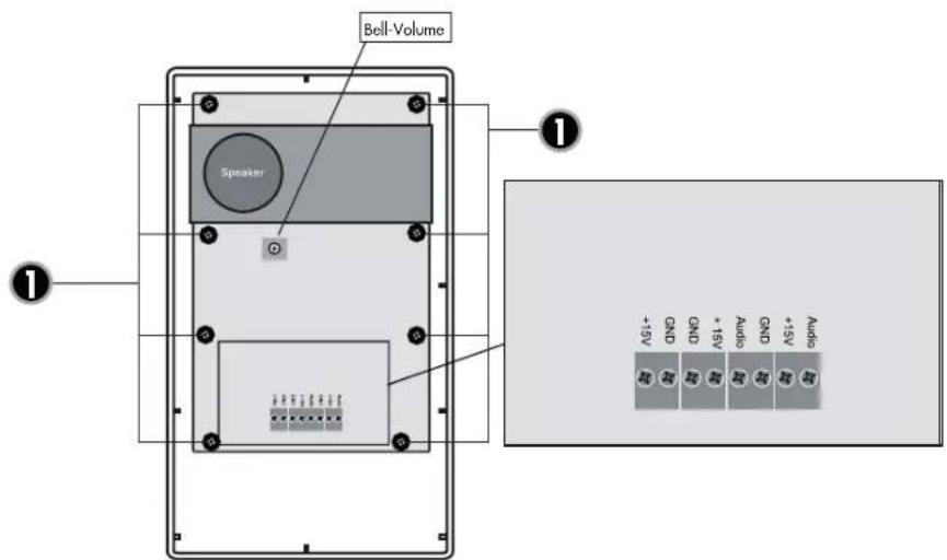
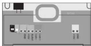
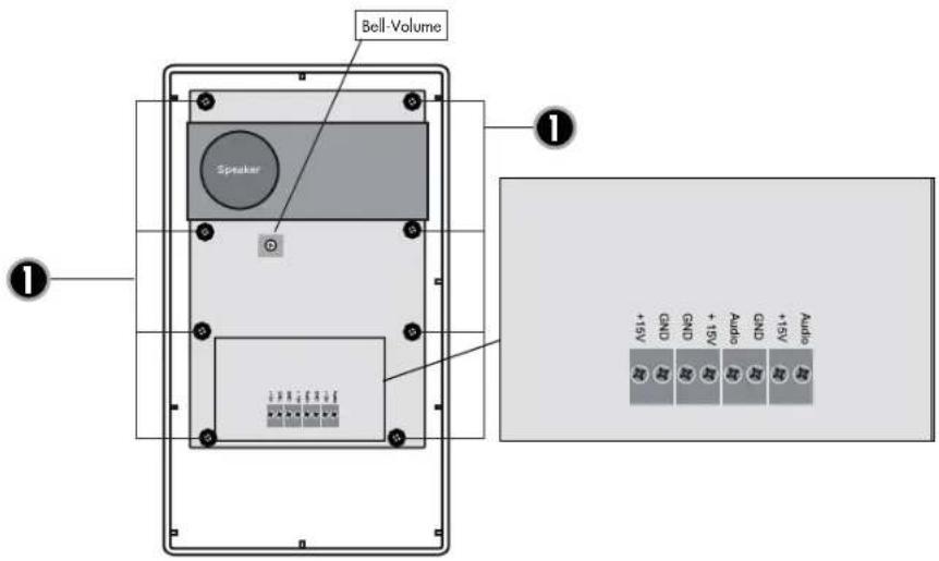
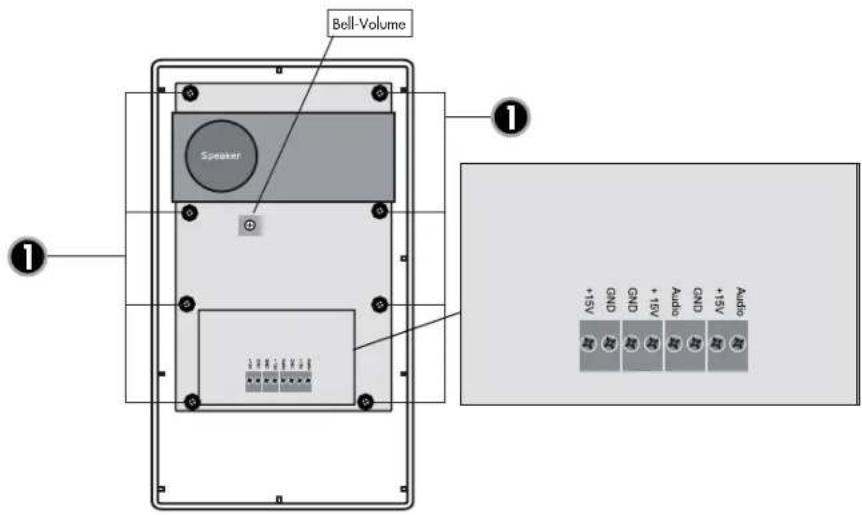
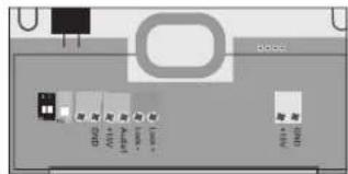
An exact description of where the individual connections and terminals are located can be found in the figures. The recommended wiring can be seen in the corresponding wiring plan in the affix.
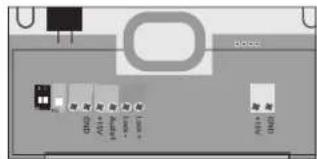
Connect the lines to the audio, +15V and GND on the outdoor station. These terminals are also present on the indoor stations and need to be connected to one another 1:1.

Note on the 2-family version: One four-pole connection terminal is present in each residential unit. The connection terminals are numbered. Connection terminal 1 is for the lower and connection terminal 2 is for the upper bell button.

Note on the 3-family version: One four-pole connection terminal is present in each residential unit. The connection terminals are numbered. Connection terminal 1 is for the lower, connection terminal 2 is for the middle and connection terminal 3 is for the upper bell button.
Connecting the door opener
The door opener is connected directly to the outdoor station with two lines (Figure A, 'Door opener'). No additional power supply is necessary in order to control the door opener. The door opener must be designed for 12 volt DC voltage and may not require more than 0.9A of power. In the event that the door opener needs to be correctly polarised then both connection terminals must be marked 'lock +' and 'lock -'.

Note: In order to prevent a door opening by tampering of the outdoor station, we recommend the installation of the separately available security door opener module SDO-10, which is mounted in the service entrance box. The SDO-10 is also suitable for motor locking systems and offers several adjustable door opening times and an auto-door-open function.
Connecting the power supply
The power supply can be connected to either the indoor or the outdoor station. Separate spring clips are present for this purpose.
It is also possible to connect the power supply directly to the signal line e.g. from the fuse box to the outdoor and indoor units. The power supply unit then needs to be connection with the ground (GND) and +15V. Open power supply unit can supply up to 8 units with power.
Connecting a floor button
Any floor button that is present (normal closing contact) is connected in parallel to the terminals 'audio' and 'GND'.

On the 2- and 3-family versions please note that the correct audio line is used (Audio1 and GND for family 1, Audio2 and GND for family 2 and Audio3 and GND for family 3).

Note: If a floor button is connected then an unchangeable ring tone is played when the floor button is activated. This ring tone is fixed and is not included in the 'normal' tones/melodies to make it easy to differentiate.
Connecting the wireless expansion model VTX-BELL
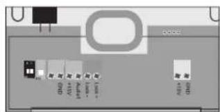
The VTX-BELL can be used to send the bell signal wirelessly to the receiver in the BELL series (currently BELL 200 RX, BELL 210 USB and BELL 220 RX). The wireless module will be attached to the 3-pole plug inside the indoor station (Figures C). For more information please see the VTX-BELL instructions.
The plug for the VTX-Bell transmitter is located on the front of the main PCB. To install the transmitter, unscrew the PCB from the housing. Remove the eight screws which connect the PCB to the housing (Fig. C No. 1). Then remove the PCB and turn it over. A 3-pin plug is located at the top of the PCB. It is labelled with Signal, GND and VCC. Attach the
transmitter connecting cable to the plug so that yellow is connected to Signal, black to GND and red to VCC. Turn the PCB over again and route the cable to the back of the PCB as shown in Fig. 2 B. Make sure that the cable is not squeezed at any point. Screw the PCB back on using the eight screws.
Now connect the transmitter to the cable and fix it in place with a piece of adhesive tape.
Alternatively, the VTX-Bell can also be attached directly to the plug, however the button for selecting the bell tone on the VTX-Bell will no longer be easily accessible.
POSSIBLE SETTINGS ON THE OUTDOOR STATION
The outdoor station has the following possibilities of adjusting the system to your personal circumstances:
Volume on the outdoor station
The potentiometer (Figure A, Volume / Lautstärke') is used to set the speaking volume on the outdoor station. For full volume turn the potentiometer carefully in a clockwise connection until it stops and turn it back a little. Turning the potentiometer in an anti-clockwise direction reduces the volume.
ID code
If several outdoor stations are used in parallel (e.g. on the gate and on the house), the DIP switch is used to set the ID code (Figure A, 'ID-CODE').
ID1 = Switch 1 'on', Switch 2 'on'
ID2 = Switch 1 'on', Switch 2 'off'
ID3 = Switch 1 'off', Switch 2 'on'
Door opener time
The DIP switch (Figure A, 'Door opener time') is used to set how long the door opener should be activated for. The possible settings are 1 second or 5 seconds. 5 seconds is the factory setting and works for most standard door openers.
Switch 'off' corresponds to an opening time of 1 second.
Switch 'on' corresponds to an opening time of 5 seconds.
POSSIBLE SETTINGS ON THE INDOOR STATION
The following settings are possible on the indoor station to adjust the system to your personal circumstances:
Ring tone volume
The potentiometer (Figure C 'Bell Volume') is used to set the ring tone volume on the indoor station. For full volume turn the potentiometer carefully counter-clockwise until it stops. Turning the potentiometer clockwise reduces the volume.
∅
Deactivate ring tone/melody (e.g. during the night)
The ring tone/melody can be deactivated, e.g. in order to prevent disturbance during the night. Either press the mute button on the indoor unit once briefly. The LED below the mute button lights up red as a reminder that the melody is deactivated. To activate the melody again press the mute button again briefly. When the red LED goes out the melody has been re-activated.
The optical signal (surround light on the talk and door opener button) remains active, even then the ring tone/melody is deactivated and still rings. The red LED flashes if the bell is rung while the mute is activated.
i
NOTE: If the VTX-BELL module is used then this will also be deactivated in the silent mode, i.e. the connected receivers will not give a signal either.
A
IMPORTANT: The indoor station needs to be activated for the following settings (e.g. by pressing the talk button). Otherwise it is not possible to set the talk/volume, and melody.
[Non-Text]
Speaking volume
The two side buttons (B. 12 and 13) can be used to set the speaking volume in several steps. Button 12 is used to increase the volume and button 13 to reduce it.
[NO TEXT]
Melody selection
The next melody is played every time you press the 🎨 button (B/C.11). The last melody to be played is automatically stored.
OPERATION (as door intercom system)
- Press the bell button.
- The stored ring tone will play on the corresponding indoor station(s)
- Accept the conversation on the indoor unit by pressing briefly on the talk button (→)
- Accept the conversation on the indoor unit by pressing briefly on the talk button (→)
-
- If a door opener is connection then you can activate it by briefly pressing the door opener button (→)The bell button will light green for the duration of the door opener as confirmation.
- Press the talk button ( ) briefly in order to switch the system back to standby operation.
i
Note: If a floor button is connected then an unchangeable ring tone is played when the floor button is activated. This ring tone is fixed and is not included in the 'normal' tones/melodies to make it easy to differentiate.
图
OPERATION (as internal house intercom)
All indoor units that are connected to the same bell button can also be used as an internal intercom.
- Press the internal button (B. 7) on the indoor station from which you wish to reach another indoor station. All the connected indoor station will ring. No image will be shown.
- To accept the conversation on one of the other connected indoor stations you need to briefly press the talk button there (B. 6).
- The talk button needs to be pressed briefly on one of the two indoor stations in order to end the conversation.
i
Note: It is not possible to set different ring tones for internal and external calls.
Technical data:
Outdoor station
Operating voltage: 15V DC
Standby power: <0.5W
Connection for door opener: \~12V DC, max. 0.9 A
Bell button illumination: automatic via CDS sensor
Indoor station
Operating voltage: 15V DC
Standby power: <0.5W
NOTES
The functionality of the unit can be affected by the influence of strong static, electrical or high frequency fields (discharging, mobile phones, radios, microwaves).
NAME
[NO TEXT]
Cleaning and maintenance
Always disconnect mains powered units from the mains supply before cleaning (disconnect the plug). The unit housing can be cleaned using a soapy soft cloth. Do not use any abrasive materials or chemicals. Remove dust build-up from ventilation slits using a brush and clean up using a vacuum cleaner. Do not hold the vacuum cleaner nozzle directly against the unit.
SAFETY INSTRUCTION
In the event of damage to the housing, connectors, power cables or isolation shielding, switch off the device immediately and disconnect from the mains power. ELECTRIC SHOCK - DANGER OF LOSS OF LIFE. (Unplug the mains connector from the socket!). Damage should be repaired immediately by a specialist!

Do not take the product apart! There is a danger of lethal electric shock!

Never carry out repairs yourself!
For reasons of safety and licensing (CE), unauthorised conversion and / or modification of the product is prohibited.
The design of the product complies with protection class 1. Only a standard mains socket (230V\~/50Hz) of the public mains supply may be used to power the device. Devices powered by mains voltage must be kept away from children. Please therefore be particularly careful in the presence of children.
Do not leave packaging material lying about since plastic foils and pockets and polystyrene parts etc. could be lethal toys for children. The interior unit is suitable only for dry interior rooms (not bathrooms and other moist places). Do not allow the devices to get moist or wet. There is a danger of lethal electric shock!
Please consult a specialist should you have doubts regarding the method of operation, the safety, or the connections of the device.

Handle the product with care - it is sensitive to bumps, knocks or falls even from low heights.
WARRANTY
2 years warranty from date of purchasing, on base of correct using.
The producer is not responsible for consequential damages which are effected directly or indirectly from this item.
The warranty will be null and void in case of damages arising from violations of these operating instructions. We are not liable for consequential damages!
We accept no liability for material damages or injuries arising from inappropriate use or violation of the safety instructions. In such cases all warranty claims are null and void!
GB
These operating instruction are published by m-e GmbH modern-electronics, An den Kolonaten 37, 26160 Bad Zwischenahn/Germany
The operating instructions reflect the current technical specifications at time of print. We reserve the right to change the technical or physical specifications.
A
Abb. A
DIAGRAM A
ILLUSTRATION A
AFBEELDING A
AUSSENSTATION • OUTDOOR STATION • BOÎTIER EXTÉRIEUR • BUITENSTATION
text_image
2 NAME 1 ▲ NAME 2 ▲ NAME 3 ▲ 3 6 4 5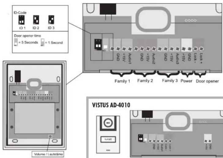
text_image
ID-Code ID 1 ID 2 ID 3 Door opener time = 5 Seconds = 1 Second Family 1 Family 2 Family 3 Power Door opener VISTUS AD-4010 NAME Volume / Autstärke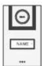
text_image
0000 电源 电源 电源 电源 电源 电源 + 15A + 15A + 15A + 15A + 15A + 15A + 15A + 15A + 15A + 15A + 15A + 15A + 15A + 15A + 15A + 15A + 15A + 2000 + 2000 + 2000 + 2000 + 2000 + 2000 + 2000 + 2000 + 2000 + 2000 + 2000 + 2000 + 2000 + 2000 + 2000 + - - - - - - - - - - - - - - - - - - - - - - - - - - - - - - - - - - - - - - - - - - - - - - - - - - - - - - - - - - - - - - - - - - - - - - - - - - - - - - - - - - - - - - - - - - - - - - - - -INNENSTATION • INDOOR STATION • BOÎTIER INTÉRIEUR • BINNENSTATION
natural_image
Front view of a rectangular electronic device with mounting holes and a central circular component (no text or symbols)FR
INNENSTATION • INDOOR STATION • BOÎTIER INTÉRIEUR • BINNENSTATION
C Abb. C DIAGRAM C ILLUSTRATION C AFBEELDING C
text_image
Bell-Volume Speaker +15V GND GND +15V Audio GND +15V Audio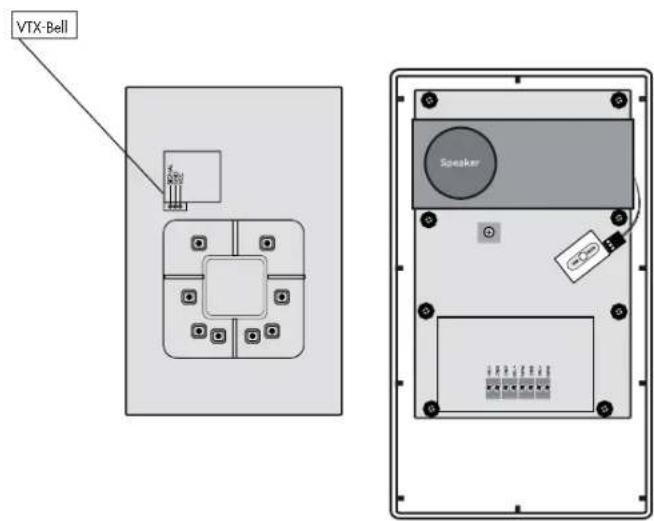
text_image
VTX-Bell SpeakerINTRODUCTION
B. 6 = touche de conversation
The image is too blurry to recognize any text content.
B. 7 = touche de communication interne
♪
B.11 = sonnerie
⊕
B.12 = volume +
-
B.13 = volume -
VISTUS AD-4020: 71 mm x 25 mm
VISTUS AD-4030: 71 mm x 15mm
Alimentation: 15 V CC
text_image
ID-Code ID 1 ID 2 ID 3 Door opener time = 5 Seconds = 1 Second Family 1 Family 2 Family 3 Power Door opener VISTUS AD-4010 NAME Volume / Lautstärke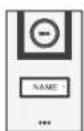
text_image
GPIO USB +10V +10V +10V +10VINNENSTATION • INDOOR STATION • BOÎTIER INTÉRIEUR • BINNENSTATION
B
Abb. B
DIAGRAM B
ILLUSTRATION B
AFBEELDING B
text_image
③ ④ ⑤ ⑦ ⑥ ⑮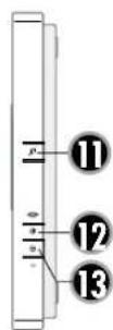
natural_image
Front view of a rectangular electronic device with mounting holes and a central circular component (no text or symbols)INNENSTATION • INDOOR STATION • BOÎTIER INTÉRIEUR • BINNENSTATION

Abb. C
DIAGRAM C
ILLUSTRATION C
AFBEELDING C

text_image
Bell-Volume Speaker 1 +1V GND GND +1V Audio GND +1V Audio 1 1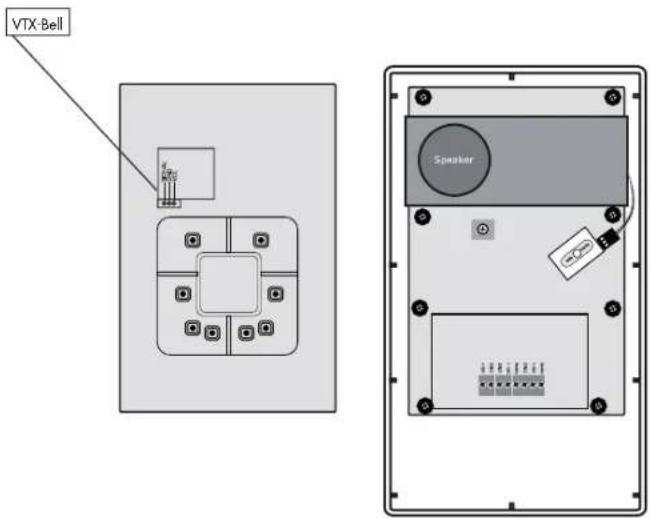
text_image
VTX-Bell SpeakerNL
INLEIDING
VISTUS AD-4020: 71 mm x 25 mm VISTUS AD-4030: 71 mm x 15mm
text_image
NAME 3 NAME 2 NAME 1
STUS

text_image
| VISTUS ADnatural_image
Simple diagram of a square grid with directional arrows and symbols, no readable text or labels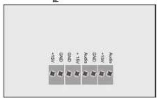
text_image
AV+- CHD CHD AV+- SPN CHD AV+ AR AR AR AR AR AR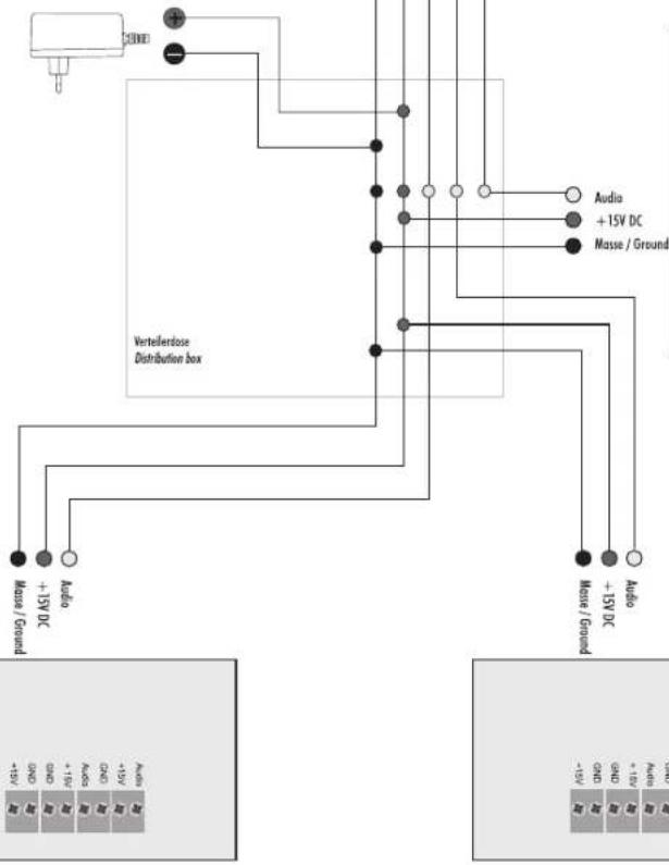
text_image
Vertelderdose Distribution box Audio +15V DC Audio +15V DC Masse / Ground Audio +15V DC Audio +15V DC Masse / Ground Masse / Ground Masse / Ground Masse / Ground Masse / Ground Masse / Ground Masse / Ground Masse / Ground Masse / Ground Masse / Ground Masse / Ground Masse / Ground Masse / Ground Masse / Ground Masse / Ground Masse / Ground Masse / Ground Masse / Ground Masse / Ground Masse / Ground Masse / GND Masse / GND Masse / GND Masse / GND Masse / GND Masse / GND Masse / GND Masse / GND Masse / GND Masse / GND Masse / GND Masse / GND Masse / GND Masse / GND Masse / GND Masse / GND Masse / GND Masse/ GND Masse/ GND Masse/ GND Masse/ GND Masse/ GND Masse/ GND Masse/ GND Masse/ GND Masse/ GND Masse/ GND Masse/ GND Masse/ GND Masse/ GND Masse/ GND Masse/ GND Masse/ GND Masse/ GND N30000000000000000000000000000000000000000000000000000000000000000000000000000000000000000000000000000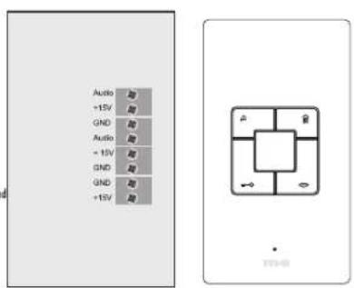
text_image
Audio +15V GND Audio - 15V GND GND +15V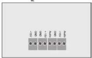
text_image
GND GND + GW GND GND + GW +W +W +W