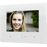
VDV-807 - Intercom m-e - Free user manual and instructions
Find the device manual for free VDV-807 m-e in PDF.


| Product type | Indoor video intercom |
| Brand | m-e |
| Model | VDV-807 |
| Screen size | 17.8 cm (7 inches) |
| Screen resolution | 1024 x 600 pixels |
| Power supply | 15 V DC |
| Power consumption | 270 ± 50 mA |
| Operating temperature | 0 to +50 °C |
| Maximum ambient humidity | 85 % |
| Radio frequency | 433 MHz (<10 mW) |
| Main functions | Doorbell, intercom, door opening, camera switching, alarm, intercom between indoor units |
| Ringtone type | Internal and customizable melodies via SD card (MP3/WAV files, max 16) |
| Memory | Micro SD card up to 32 GB (FAT32 format) |
| Built-in radio | Compatible with BELL and FG series radio doorbells (modifiable coding) |
| Buttons and controls | Microphone, screen, door opening, intercom, standby, volume, melody, alarm/intercom, minus, plus, menu |
| Installation | Wall mounting with drilling template, 4 screws, wired connection |
| Cleaning and maintenance | Damp cloth with soapy lotion, no abrasive products; dust the grilles with a brush |
| Safety | Disconnect before cleaning, do not disassemble, use in dry environment, avoid moisture |
| Warranty | 2 years limited (excluding order error, batteries, radio interference, mechanical damage, moisture) |
| Package contents | Indoor unit with screen, mounting hardware, user and installation manual, drilling template |
Frequently Asked Questions - VDV-807 m-e
User questions about VDV-807 m-e
0 question about this device. Answer the ones you know or ask your own.
Ask a new question about this device
Download the instructions for your Intercom in PDF format for free! Find your manual VDV-807 - m-e and take your electronic device back in hand. On this page are published all the documents necessary for the use of your device. VDV-807 by m-e.
USER MANUAL VDV-807 m-e
2A
2B
3
DE
4
DE
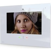
Thank you for purchasing this video internal unit. It can be combined with all components from the VISTADOOR and VISTUS systems. When the linked external unit is rung, the internal unit plays the set bell tone and the visitor can be seen on the monitor. You can then speak with the visitor and also open the door (provided a door opener is linked).
CONTENTS
Internal unit with 17.8 cm (7") screen size
Fixings
Operating and installation instructions
Drilling template
Key
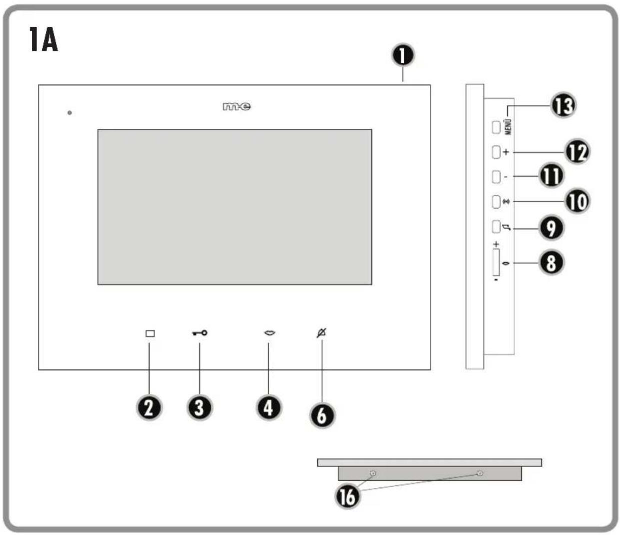
1 = Microphone
□ 2 = Monitor button
3 = Door opener button
4 = Voice button
∅ 6 = Sleep button
— 8 = Voice volume adjuster
♪ 9 = Bell tone button
3 10 = Alarm/intercom button
- 11 = Minus button
+ 12 = Plus button
13 = Menu button
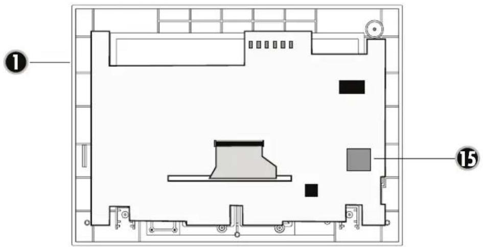
15 = Slot for micro SD card
16 = Housing screws
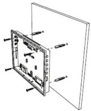
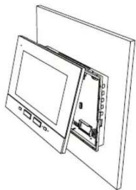
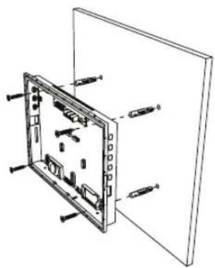
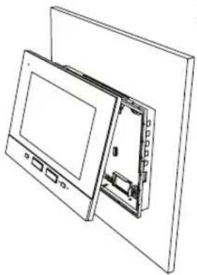
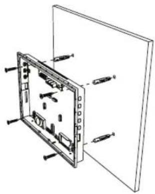
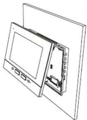
INSTALLATION (Fig. 2a+b)
- Identify a suitable place to fit the internal unit and lay all the cables needed to this point.
- Remove the two screws (16) from the internal unit and lift the front cover off the unit.
- There are two attachment clips at the centre of the sides of the internal unit. Carefully pull off the front cover.
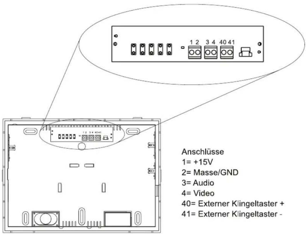
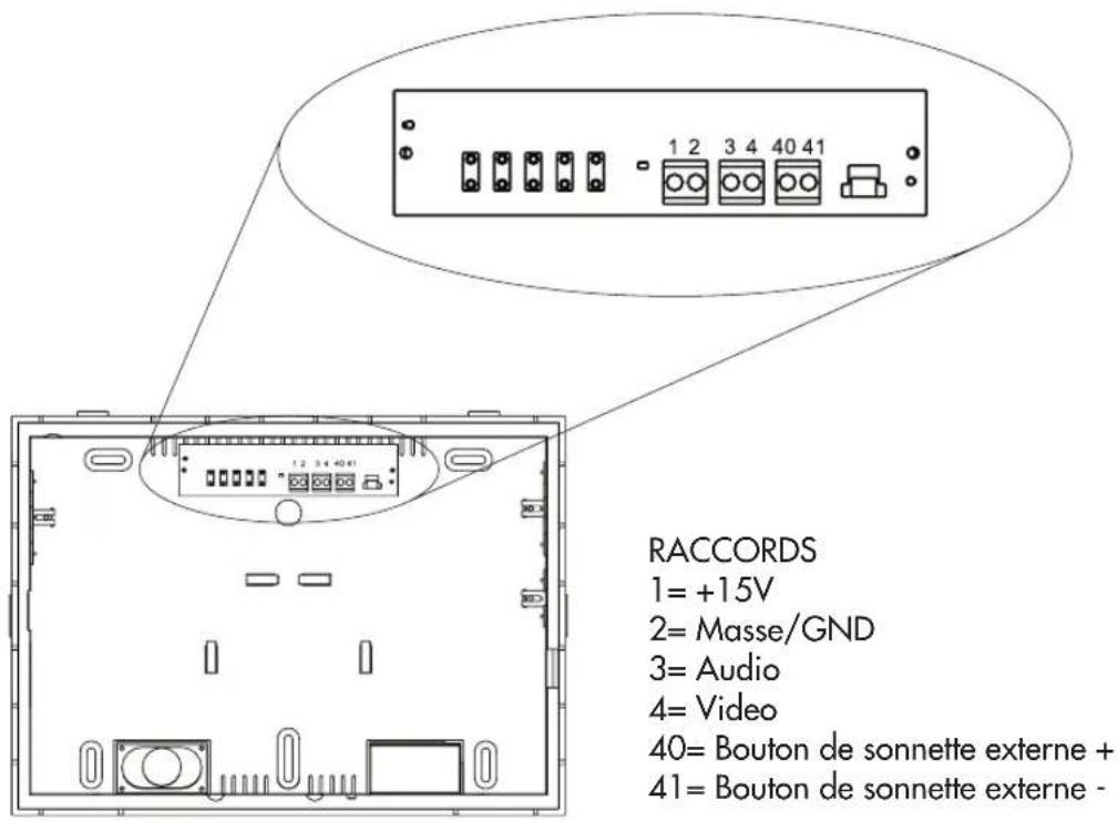
- For cable entry into the housing, the latter has a hole in it at the top below the connection terminals.
- Use a spirit level to correctly align the supplied drilling template at the point on the wall where the internal unit is to be fitted. Alternatively, the back of the internal unit housing can be used to mark the drill holes.
- Fix the drilling template in position with adhesive tape and drill the four marked holes ( 6 mm).
- Take the drilling template off and insert one of the plugs supplied in each of the holes.
- Feed the connecting cable through the hole in the bottom of the internal unit housing and screw the housing to the wall using the four screws.
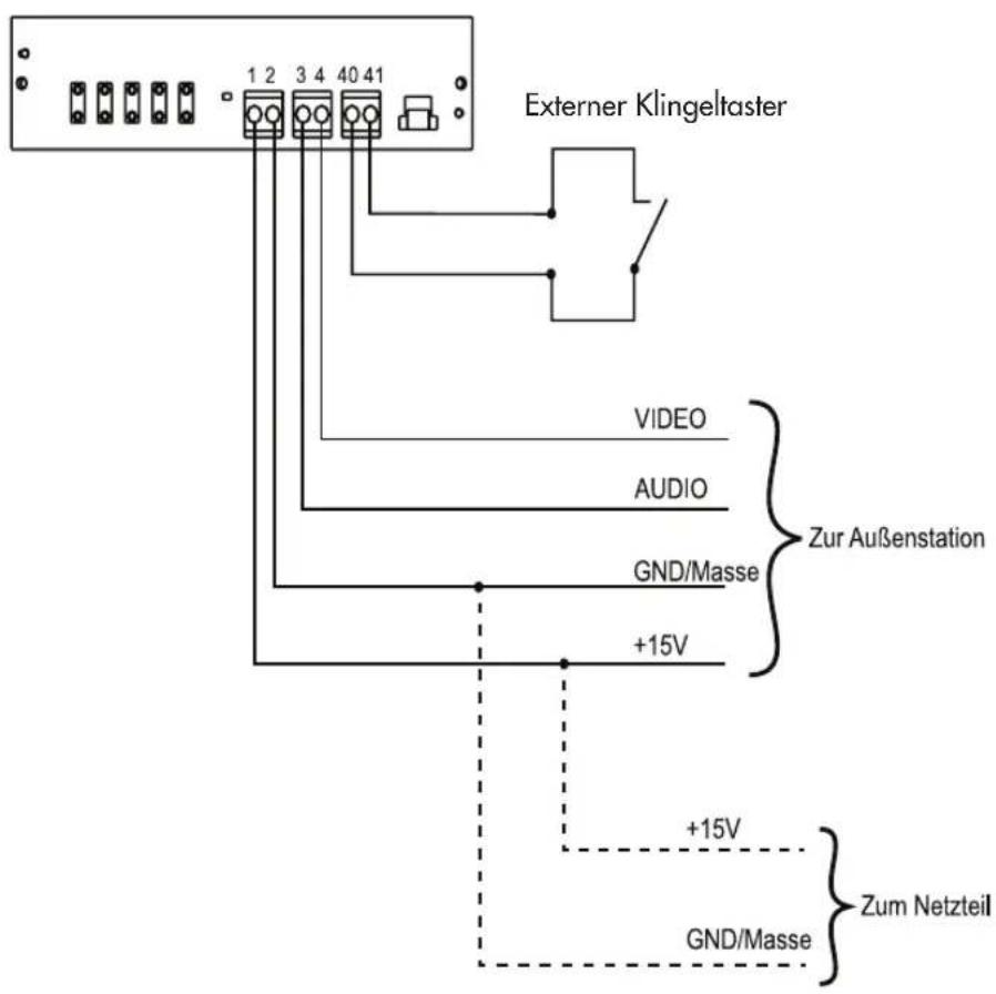
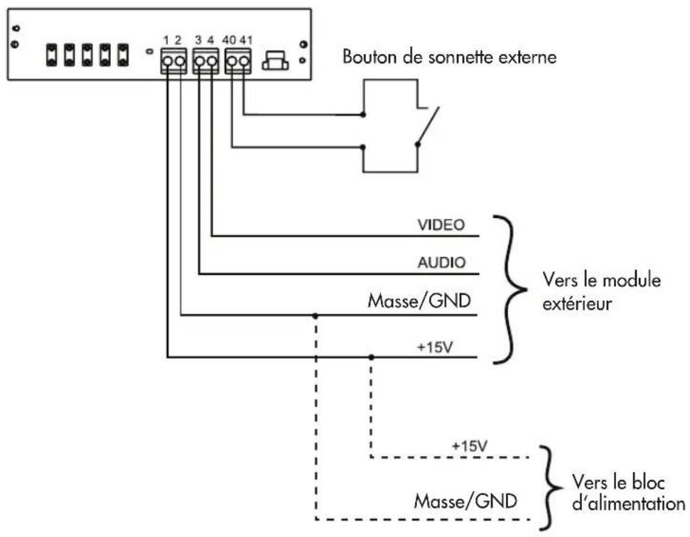
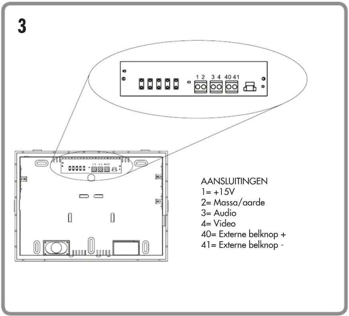
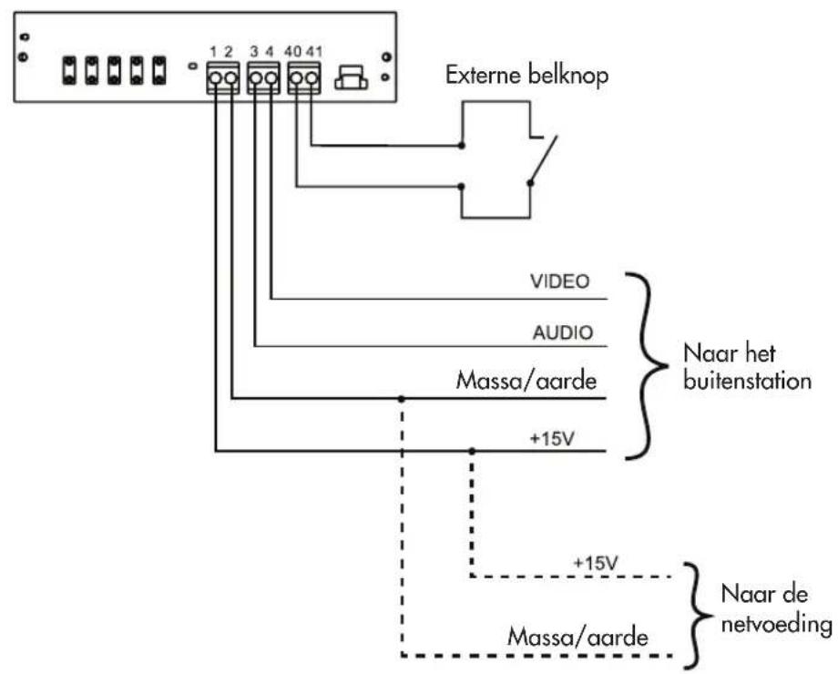
- Connect the cables as shown in the wiring diagram (Fig. 4).
NOTE: Do not cut the cables too short. There are clips in the bottom of the housing that the cable can be wound around.
- Attach the front cover with the monitor. Make sure that the attachment clips engage properly.

NOTE: Also make sure that any bare wires do not touch the PCB shielding; ideally the wires should be as short as possible.
- Screw the front cover back on using the two screws (16).
STARTUP
Connecting the power supply
The power supply can be connected to the internal or external unit, as preferred.
The power supply can also be fed in at a star point, if all the signal cables have been laid from the fuse box to the external and internal units, for instance. The power supply unit should then be connected in parallel to ground/GND and +15 V. Once all the components have been fitted and connected, switch on the operating voltage. Depending on the type of installation, either plug the mains adapter into a suitable socket or switch on the circuit breaker that is connected to the DIN rail power supply unit. Ring the external unit once to initialise the system (if multiple external units are installed, each external unit must be rung once).

NOTE: Switch the operating voltage off again before carrying out any work on the system!
OPERATION
Ringing the external unit sounds the bell tone on the internal unit, and the visitor is displayed on the monitor. In addition, the integrated radio module sends a signal to connected doorbell receivers of the BELL and FG series (if available).
Press the voice button (4) to establish voice communication. Having spoken to the visitor, you can open the door (if a door opener is linked) by pressing the door opener button (3) or end the conversation by pressing the voice button again. This returns the internal unit to standby mode.
If multiple external units and/or additional cameras are linked, you can switch to the other external units/additional cameras by pressing the monitor button (2). This can be done at any time, even if the bell has not been rung.
Voice communication is not possible while the image from an additional camera is active.
Pressing the voice button twice returns the internal unit to standby mode. If a button is not pressed, the monitor switches off automatically after approximately 60 seconds.
SYSTEM FUNCTIONS
Ringing
If the bell push on the external unit is pressed, the internal unit emits the bell tone that has been set, and the luminous surrounds of the voice button and door opener button on the internal unit flash for approximately 60 seconds. The monitor
is also activated during this time and the image from the external camera can be seen.
Voice communication
Press the voice button once. The luminous surround of the voice button lights up blue while voice communication is active.
To terminate voice communication, press the voice button again. You can re-establish voice communication at any time. The bell does not need to be rung first. Simply press the voice button again.
- Door opening
A linked door opener is activated for approximately 6 seconds or 1 second by briefly pressing the door opener button (see instructions for the external unit used). You do not have to hold the door opener button down. Confirmation is provided by a double beep sound at the external and internal unit, and the name tag lights up green for the time the door opener is activated.
The door opener can be activated if:
- The bell has been rung (without having to establish voice communication first, within 60 seconds).
- The reply function is active.
Adjusting the voice volume
The voice volume adjuster (8) on the side of the internal unit allows you to freely adjust the volume of voice reception from the visitor.

Deactivating the bell tone (e.g. if night-time quiet is required) The bell tone can be deactivated. To do this, press the sleep button (6) of the internal unit once briefly. The LED (5) flashes red to remind you that the tone is deactivated. To reactivate the bell tone, press the sleep button briefly again. The LED will stop flashing and the bell tone is reactivated. The optical signal (luminous surrounds of the voice and door opener button) remains active even when the bell tone is deactivated and will continue to indicate the bell being rung.
NOTE: The integrated radio module is also deactivated in sleep mode, i.e. the connected receivers also do not emit a signal.
③ Activating the alarm tone
The external unit can emit an alarm tone (e.g. where someone is making a nuisance of themselves). To do this, press and hold down the alarm/intercom button (10) on the internal unit. The alarm tone will only be emitted if the button is pressed and held down within 60 seconds of the bell being rung, or if voice communication is established.
Intercom
If multiple internal units are connected together in parallel, these internal units can communicate with one another. When the alarm button is pressed in standby mode, all the internal units that are linked in parallel ring (all internal units of the same party). Voice communication is activated when the voice button is pressed on one of the ringing internal units. To terminate voice communication, press the voice button.

□ Activating monitor / switching between additional cameras
Using the monitor button (2), you can monitor the entrance area at any time without waiting for someone to press the bell push. The monitor can only be switched off by pressing the voice button twice or waiting approximately 60 seconds for the system to automatically return to standby mode.
NOTE: If an additional camera is connected (or multiple external units), it can also be activated using the monitor button. Pressing the monitor button once activates the camera of the external unit, pressing it a second time switches to the first additional camera, and pressing it a third time switches to the second additional camera. Once you flipped through all the cameras the image from the first camera is shown again.
Integrating a radio doorbell
To connect a radio doorbell from the BELL or FG series, set it to learning mode (see the instructions for the radio doorbell) and then press the bell button on the front-door station once.
NOTE: It is also possible to teach the radio doorbell directly via the indoor unit. To do this, call up the OSD with the menu button, switch to the last item there and then press the plus or minus button. This also triggers the radio module.
SETTINGS
The following options are available at the indoor unit to adjust the system to your personal circumstances:
IMPORTANT: For the following setting options, the monitor of the indoor unit must be activated (e.g. by pressing the screen button). Otherwise, no adjustment of speech volume, brightness, contrast, colour saturation and melody is possible.
OSD settings
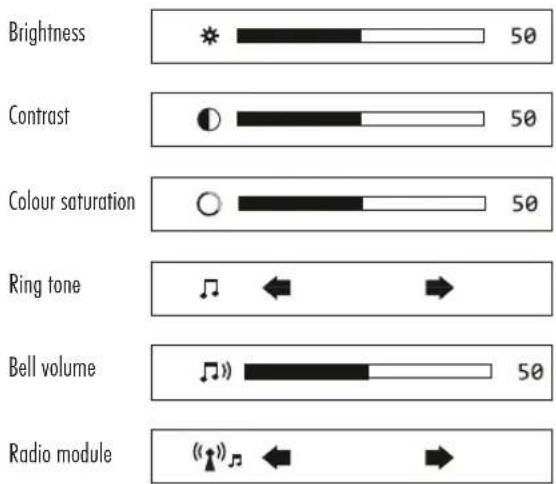
The following settings are made via the on-screen display (OSD). To call up the OSD, briefly press the menu button (13) on the indoor unit. Each additional short press of the menu button advances one menu item. The respective value can be adjusted via the plus and minus keys (12 and 11). The values are saved automatically. The OSD switches off automatically 6 seconds after the last key is pressed.
Own melody on memory card (max. 32 GB)
This intercom allows you to select your own ringtones, which you can save in MP3 or WAV format on a micro SD card. The memory card must be formatted with FAT32. You save your ringtones directly on the SD card (without using folders), a maximum of 16 different ringtones can be saved on the SD card. Insert the SD card prepared in this way into the SD card slot (15) of the indoor station. The ringtones on the memory card replace the internal ringtones. If the memory card is removed again, the internal melodies are available again.
Radio module
Use this setting to change the ringing melody of a connected radio doorbell receiver from the BELL or FG series.
Changing the coding of the internal radio module
In the event of an overlap with other radio doorbells in the neighbourhood, the transmitted code can be changed. To do this, press and hold the Alarm/Intercom button (10) for 5 seconds; a successful code change is indicated by an acoustic signal. After this procedure, the radio doorbell must be reset and relearned (see instructions for the radio doorbell).
TECHNICAL DATA
Operating voltage: 15 V DC
Power consumption: 270 ± 50 mA
Temperature range: 0 to +50°C
Maximum air humidity: 85%
Screen size: 178mm (7")

GB
Monitor resolution: 1024x600
Dimensions: 220 x 160 x 28 mm (wxhxd)
Frequency: 433 MHz; <10mW
NOTES
The functionality of the unit can be affected by the influence of strong static, electrical or high frequency fields (discharging, mobile phones, radios, microwaves).
Cleaning and maintenance
Always disconnect mains powered units from the mains supply before cleaning (disconnect the plug). The unit housing can be cleaned using a soapy soft cloth. Do not use any abrasive materials or chemicals. Remove dust build-up from ventilation slits using a brush and clean up using a vacuum cleaner. Do not hold the vacuum cleaner nozzle directly against the unit.

SAFETY NOTES
The warranty will be null and void in case of damages arising from violations of these operating instructions. We are not liable for consequential damages!
We accept no liability for material damages or injuries arising from inappropriate use or violation of the safety instructions. In such cases all warranty claims are null and void! For reasons of safety and licensing (CE), unauthorised conversion and/or modification of the product is prohibited.
22


Do not take the product apart! There is a danger of lethal electric shock!
Do not leave packaging material lying about since plastic foils and pockets and polystyrene parts etc. could be lethal toys for children.
The device is suitable only for dry interior rooms (not bathrooms and other moist places). Do not allow the device to get moist or wet. There is a danger of lethal electric shock!
In industrial institutions, the accident prevention regulations of the Association of Commercial Professional Associations for electrical installations and equipment must be observed. Please consult a specialist should you have doubts regarding the method of operation, the safety, or the connections of the device.
Handle the product with care - it is sensitive to bumps, knocks or falls even from low heights.
2 YEAR LIMITED GUARANTEE
For two years after the date of purchase, the defect-free condition of the product model and its materials is guaranteed. This guarantee is only valid when the device is used as intended and is subject to regular maintenance checks. The scope of this guarantee is limited to the repair or reinstallation of any part of the device, and is only valid if no unauthorised modifications or attempted repairs have been undertaken. Customer statutory rights are not affected by this guarantee.

Please note!
No claim can be made under guarantee in the following circumstances:
• Operational malfunction
• Empty batteries or faulty accumulator
- Erroneous coding/channel selection
- Fault through other radio installation
(i.e. mobile operation)
• Unauthorised modifications / actions
- Mechanical damage
- Moisture damage
• No proof of guarantee (purchase receipt)
Claims under warranty will be invalidated in the event of damage caused by non-compliance with the operating instructions. We do not accept any responsibility for consequential damage! No liability will be accepted for material damage or personal injury caused by inappropriate operation or failure to observe the safety instructions. In such cases, the guarantee will be rendered void.
Liability limitation
The manufacturer is not liable for loss or damage of any kind including incidental or consequential damage which is the direct or indirect result of a fault to this product.
These operating instruction are published by m-e GmbH modern-electronics, An den Kolonaten 37, 26160 Bad Zwischenahn/Germany
The operating instructions reflect the current technical specifications at time of print. We reserve the right to change the technical or physical specifications.
1B
2A
2B
3
4
Dimensions: 220x160x28mm
2A
2B
4
- CONTENTS
- KEY
- INSTALLATION (FIG. 2A+B)
- STARTUP
- CONNECTING THE POWER SUPPLY
- OPERATION
- SYSTEM FUNCTIONS
- RINGING
- VOICE COMMUNICATION
- DOOR OPENING
- THE DOOR OPENER CAN BE ACTIVATED IF
- ADJUSTING THE VOICE VOLUME
- ③ ACTIVATING THE ALARM TONE
- INTERCOM
- ACTIVATING MONITOR / SWITCHING BETWEEN ADDITIONAL CAMERAS
- INTEGRATING A RADIO DOORBELL
- SETTINGS
- OSD SETTINGS
- OWN MELODY ON MEMORY CARD (MAX. 32 GB)
- RADIO MODULE
- CHANGING THE CODING OF THE INTERNAL RADIO MODULE
- TECHNICAL DATA
- NOTES
- CLEANING AND MAINTENANCE
- SAFETY NOTES
- DO NOT TAKE THE PRODUCT APART! THERE IS A DANGER OF LETHAL ELECTRIC SHOCK
- 2 YEAR LIMITED GUARANTEE
- PLEASE NOTE
- LIABILITY LIMITATION
Brand : m-e
Model : VDV-807
Category : Intercom