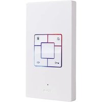
ADB-40 - Intercom m-e - Free user manual and instructions
Find the device manual for free ADB-40 m-e in PDF.


| Product type | Video intercom with screen |
| Brand | m-e |
| Model | ADB-40 |
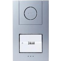
| Outdoor station dimensions | 114 × 195 × 25 mm + lens |
| Indoor station dimensions | 220 × 164 × 22 mm |
| Power supply | 15 V DC, min. 1 A |
| Outdoor station temperature range | -20 °C to +50 °C |
| Indoor station temperature range | 0 °C to +50 °C |
| Outdoor station protection rating | IP44 (protection against splashing water) |
| Compatible electric strike | 12 V DC, 1 A max |
| Display | Screen with brightness, contrast and saturation adjustments |
| Main functions | Audio/video communication, door opening, silent mode, ringtone change |
| Station coding | DIP switches for 1 or 2 family configuration |
| Connection | Bus (line+ and line-), star or daisy-chain wiring |
| Optional module | VTX-BELL for wireless ringtone extension |
| Maintenance | Clean with a damp cloth and soapy lotion; avoid abrasive products |
| Safety instructions | Disconnect before cleaning; do not repair yourself; avoid humidity |
| Warranty | 2 years limited (excluding ordering error, batteries, radio interference, mechanical damage) |
Frequently Asked Questions - ADB-40 m-e
User questions about ADB-40 m-e
0 question about this device. Answer the ones you know or ask your own.
Ask a new question about this device
Download the instructions for your Intercom in PDF format for free! Find your manual ADB-40 - m-e and take your electronic device back in hand. On this page are published all the documents necessary for the use of your device. ADB-40 by m-e.
USER MANUAL ADB-40 m-e
Thank you for purchasing the Easy2Wire intercom system. You have acquired a high-quality system with a stainless steel cover. The stainless steel covers are made carefully by hand and therefore have individual characteristics that should be considered a mark of quality.

Notes on the care of stainless steel
Never clean the stainless steel surfaces with commercial cleaning products as these are too aggressive. Please only clean them with stainless steel cleaner or care spray. If this is not available use only clear water. Failure to observe this care tip can lead to discoloration or in the worst case to rust damage.
PACKAGE CONTENTS
VDB-6170
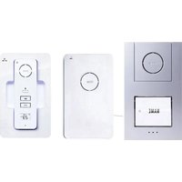
1x One-family outdoor station
1x Indoor station
1x Mounting materials
1x Operating and assembly instructions
VDB-6270
1x Two-family outdoor station
2x Indoor station
1x Mounting materials
1x Operating and assembly instructions
VDB-70
1x Indoor station
1x Mounting materials
1x Operating and assembly instructions
LEGEND
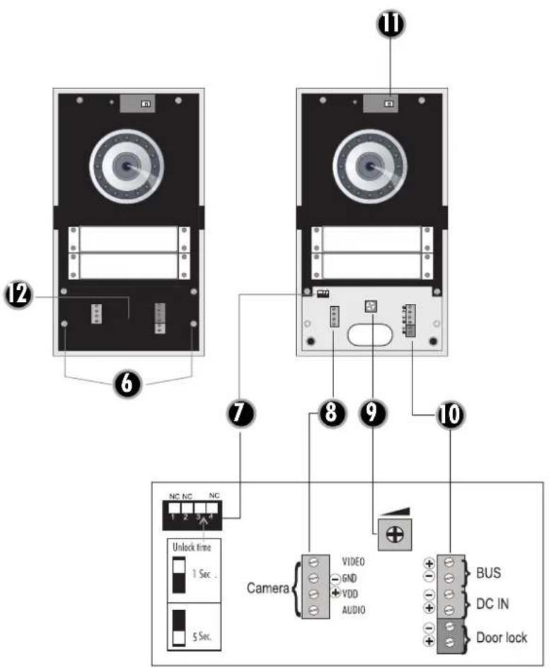
A. 1 Microphone
A. 2 Brightness sensor
A. 3 Camera
A. 4 Ringer button(s)
A. 5 Casing screws
A. 6 Screws for terminal cover
A. 7 DIP switch for opening time of door opener
A. 8 Terminal for external camera
A. 9 Volume potentiometer
A. 10 Terminal for BUS, voltage and door opener connections
A. 11 Connection plug for microphone
A. 12 Terminal cover
Indoor station
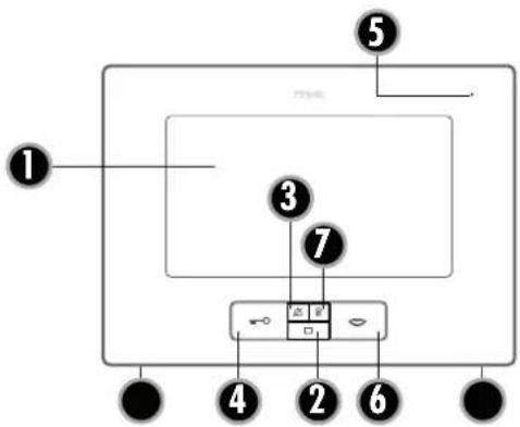
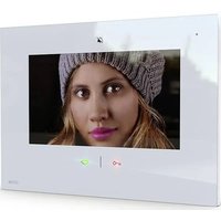
B. 1 Screen
B. 2 Screen button
B. 3 Mute button
B. 4 Door opener button
B. 5 Microphone
B. 6 Talk button
B.7 Internal button
M B.8Menu button
B. 9OSD + button
B. 10 OSD - button
B. 11 Melody
B. 12 Volume +
B. 13 Volume -
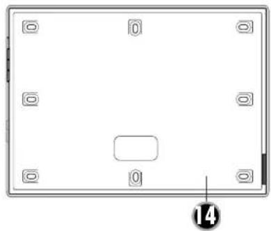
B. 14 Back of casing
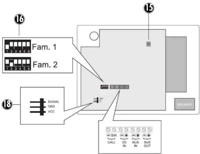
B. 15 Potentiometer for ringer volume
B. 16 DIP switch for encoding
B. 17 Casing screws
B. 18 Connection for VTX-BELL
INSTALLATION
The following wires are required
2 wires from the outdoor station to the indoor station(s) and 2 wires from the outdoor station to the door opener. The lines can either be laid radially or station-to-station. There are two 2-pole terminals in the indoor station for the BUS line (line + and line -), input and output, for a station-to-station connection. For radial wiring the BUS line is only connected to the input. The supply voltage is either connected to one indoor station or to the outdoor station. There should not be a double feed. Ensure correct poling on all connections.
Connecting a door opener
The door opener is connected directly to the outdoor station with two lines. No additional power supply is necessary to control the door opener. The door opener must be designed for 12-volt direct voltage and may not require more than 1 A current. Some door openers require correct poling.
Connecting the radio extension module VTX-BELL
The VTX-BELL can be used to transfer the bell signal by radio to the recipient of the BELL series (currently BELL 200 RX, BELL 210 USB and BELL 220 RX). The radio module is attached to the 3-pole plug (B.18) inside the indoor station. You need the short 3-pole extension that is included in the VTX-BELL.

IMPORTANT: Please only connect the mains power supply to the power once the system has been fully mounted. Otherwise short-circuiting can occur during installation, which can destroy the apparatus in the worst case.

NOTE: The outdoor station is splash proof in accordance with IP 44. In heavy rain, particularly in conjunction with high winds, it is still possible for water to penetrate the casing. We therefore recommend only mounting the station in a protected outdoor area. If it is not possible to mount the station in a protected indoor area then weather protection should be fitted over the outdoor station.
OUTDOOR STATION
Preparation
Please make sure that the nameplates do not fall out when you remove the front cover as this could damage them.
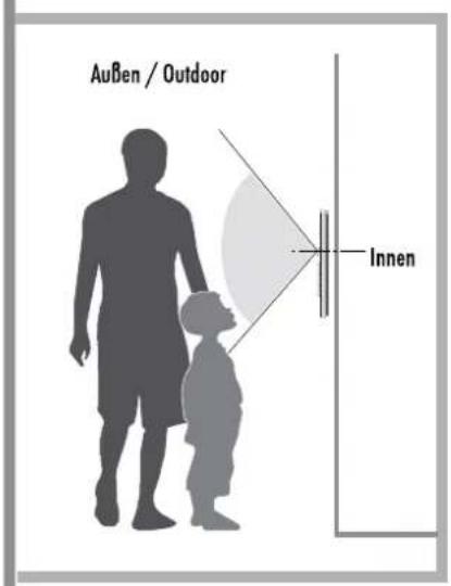
The camera should be mounted at a height of approx. 1.5m - 1.6m (middle of the camera).
- Remove both lower screws (A.5) using a suitable screwdriver (Torx T10).
- Hold the bottom of the front cover with your thumb and index finger and pull it forwards slightly. Then lift it upwards slightly. Make sure that you do not rip off the microphone cable. The microphone cable is connected to the electronics with a plug and can be separated easily by pulling it out.
- Remove the terminal cover by removing both screws (4.6) and then removing the terminal cover.
- Look for a suitable place to mount the outdoor unit and lay all the necessary wires to this location.

Note: Please ensure that the wall at the mounting location is straight and level.
- Use the casing to draw the mounting holes on the wall. A spirit level is useful to check that the outdoor station is mounted straight.
- Drill the 4 holes that you have drawn with a 6mm drill and insert one of the included dowels into each hole.
-
Feed the connection wire through the wire feed and screw the back part of the casing to the wall.
-
Connect the wire that you have laid to the terminal.
Adjusting the nameplate
The nameplate comprises two transparent plastic parts that are connected with 2 small screws.
- Remove both screws and take the nameplate apart. The foil for inscription is between the two plastic parts.
- Write on the foil with a smear-resistant felt pen or print a nameplate using a PC and printer (you can use normal paper but printable foil from stationery shop is better suited).
- Place the inscribed nameplate (foil) between the two plastic parts and screw them back together.

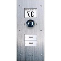
*Size of the nameplate:
VDB-6170: 71mm× 34mm
VDB-6270: 71mm× 15mm
- Insert the nameplates into the outdoor station and fix with a strip of sticky tape.
- Insert the microphone cable back into the socket and replace the front cover onto the outdoor station from above and at an angle. Please ensure you do not crush the microphone cable. The projections on the back cover must fit into the notches on the front cover.
- Then slide the front cover carefully over the outdoor station and screw the two fixing screws (A.5) back into the casing.
ASSEMBLY OF THE INDOOR STATION
You can select the mounting height for the indoor station according to your circumstances.

- The casing on the indoor station is screwed together with two screws (B.17) and is kept together with projections and notches. To separate the back section from the front section remove both screws and the back section can then be simply removed.
- Use the back section of the casing as an aid to draw the drill holes. Make sure that you place the back section in a straight line.
- Drill the mounting holes with a 6mm drill and insert one dowel into each hole.
- Feed the wires through the correct insertion hole in the back section of the casing and screw this.
- Connect the wires in accordance with the wiring plan and place the front casing section on the back casing section. Make sure that it clicks into place correctly.
- Screw the casing back together with the two screws (B.17).
SETTINGS ON THE IN- AND OUTDOOR STATIONS
ENCODING (Indoor station)
There are DIP switches (B.16) on the indoor station for encoding. Each indoor station needs to be set to the correct code. If one party has several indoor stations then the encoding must be the same for all indoor stations belonging to the party.
One-family version
DIP switch 1 ON", all others OFF"
2-family version
Indoor station(s) for family 1
DIP switch 1 ON", all others OFF"
Indoor station(s) for family 2
DIP switch 2 "ON", all others "OFF"

NOTE: If two or more indoor stations are connected then DIP switch 6 must be switched to "ON" on the last indoor station.
CONVERSATION VOLUME (outdoor station)
The conversation volume on the outdoor station is set using the potentiometer (A.9). For full volume turn the potentiometer carefully in a clockwise direction to its limit and then turn it back a little. Turn it in an anti-clockwise direction to reduce the volume.
CONVERSATION VOLUME (indoor station)
You can set the conversation volume on the indoor station in several stages using the two buttons B.12 and B.13 on the side.
RINGER VOLUME (indoor station)
The ringer volume on the indoor station is set using the potentiometer (B.15). For full volume turn the potentiometer carefully in a clockwise direction to its limit and then turn it back a little. Turn it in an anticlockwise direction to reduce the volume.
CHANGING THE RING TONE (indoor station)
The ring tone can be changed using button B.11. Press the talk button (B.6) to activate the indoor station. Then press on the melody button (B.11) and a melody will play. Keep pressing the melody button until the desired ring tone plays. To confirm the melody press the talk button. The set melody is then saved. If the system is disconnected from the mains the melody will be set back to the factory setting.
DEACTIVATING THE RINGER MELODY
(e.g. during the night)
It is possible to deactivate the ringer melody, e.g. in order not to be disturbed at night. To do this, press the mute button (B.3) on the indoor unit down once, briefly. The LED on the mute button lights up red to remind you that the melody is deactivated. To re-activate the melody press the mute button briefly again. The red LED will go out and the melody is reactivated.
The optical signal (the illuminated frame on the talk and door opener button) remains active even when the ringer melody is deactivated and continues to light up when the bell is rung. The red LED also flashes if the bell is rung while muted.

NOTE: If the VTX-BELL module is used then this is also deactivated in quiet mode, i.e. the connected receiver also does not emit a signal.
Brightness
Press the menu button (B.8) on the indoor station once and the OSD will display 'Bright'. The brightness can now be increased using the button (B.9) and reduced using the button (B.10).
Contrast
Press the menu button (B.8) twice on the indoor station and the OSD will display 'Contrast'. The contrast can now be increased using the button (B.9) and reduced using the button (B10).
Colour saturation
Press the menu button (B.8) three times on the indoor station and the OSD will display 'Color'. The colour saturation can now be increased using the button (B.9) and reduced using the button (B10).
INITIAL OPERATION
Connect the mains power supply unit to the 230V network once all the components are connected and encoded. Then ring the bell once in order to initialise the system. This initialisation needs to be carried out each time the system is disconnected from the mains.
OPERATION

-
Press the ringer button (A.4).
-
The set melody will sound at the corresponding indoor station(s).
-
Accept the conversation at the indoor station by briefly pressing on the talk button (B.6).
-
If a door opener is connected you can activate the door opener by pressing briefly on the door opener button (B.4).
- Press the talk button again briefly in order to switch the system back to standby.
TECHNICAL DATA
Outdoor station
Power consumption: 130 ± 50 ~mA
Temperature range: -20 to +50^
Dimensions: 114 × 195 × 25 mm + lens
Door opener connection: 12 volt DC/1 A max.
Splash-proof in accordance with IP 44
Indoor station
Supply voltage: 15 Volt DC / min. 1 A
Power consumption: 130 ± 50 ~mA
Temperature range: 0 to +50^
Dimensions: 220 × 164 × 22 ~mm

NOTES
The functionality of the unit can be affected by the influence of strong static, electrical or high frequency fields (discharging, mobile phones, radios, microwaves).
Cleaning and maintenance
Always disconnect mains powered units from the mains supply before cleaning (disconnect the plug). The unit housing can be cleaned using a soapy soft cloth. Do not use any abrasive materials or chemicals.
Remove dust build-up from ventilation slits using a brush and clean up using a vacuum cleaner. Do not hold the vacuum cleaner nozzle directly against the unit.

SAFETY INSTRUCTION
In the event of damage to the housing, connectors, power cables or isolation shielding, switch off the device immediately and disconnect from the mains power. ELECTRIC SHOCK - DANGER OF LOSS OF LIFE. (Unplug the mains connector from the socket!). Damage should be repaired immediately by a specialist!

Never carry out repairs yourself!
For reasons of safety and licensing (CE), unauthorised conversion and / or modification of the product is prohibited.
Do not leave packaging material lying about since plastic foils and pockets and polystyrene parts etc. could be lethal toys for children.
The interior unit is suitable only for dry interior rooms (not bathrooms and other moist places). Do not allow the devices to get moist or wet.
In industrial institutions, the accident prevention regulations of the Association of Commercial Professional Associations for electrical installations and equipment must be observed. Please consult a specialist should you have doubts regarding the method of operation, the safety, or the connections of the device.
Handle the product with care - it is sensitive to bumps, knocks or falls even from low heights.
2 YEAR LIMITED GUARANTEE
For two years after the date of purchase, the defect-free condition of the product model and its materials is guaranteed. This guarantee is only valid when the device is used as intended and is subject to regular maintenance checks. The scope of this guarantee is limited to the repair or reinstallation of any part of the device, and is only valid if no unauthorised modifications or attempted repairs have been undertaken. Customer statutory rights are not affected by this guarantee.

Please note!
No claim can be made under guarantee in the following circumstances:
- Operational malfunction
- Empty batteries or faulty accumulator
- Fault through other radio installation (i.e. mobile operation)
- Unauthorised modifications / actions
Mechanical damage - Moisture damage
No proof of guarantee (purchase receipt)
Claims under warranty will be invalidated in the event of damage caused by non-compliance with the operating instructions. We do not accept any responsibility for consequential damage! No liability will be accepted for material damage or personal injury caused by inappropriate operation or failure to observe the safety instructions. In such cases, the guarantee will be rendered void.
Liability limitation
The manufacturer is not liable for loss or damage of any kind including incidental or consequential damage which is the direct or indirect result of a fault to this product.
GB
These operating instruction are published by
m-e GmbH modern-electronics,
The operating instructions reflect the current technical specifications at time of print. We reserve the right to change the technical or physical specifications.
Abb.A DIAGRAM A ILLUSTRATION A AFBEELDING A

A
AUSSENSTATION - OUTDOOR STATION - BOTTIER EXTERIEUR - BUITENSTATION
74 INNENSTATION · INDOOR STATION · BOITIER INTERIEUR · BINNENSTATION

Abb. B
DIAGRAM B
ILLUSTRATION B
AFBEELDING B

INTRODUCTION
SYSTÉME D'INTERPHONE VIDEO Easy2Wire
VOLUME VOCAL (station interieure)
Consummation: 130± 50mA
Consummation: 130 ± 50 ~mA
CODERING (binnenstuation)
- Notes on the care of stainless steel
- PACKAGE CONTENTS
- VDB-6170
- VDB-6270
- VDB-70
- LEGEND
- Indoor station
- INSTALLATION
- The following wires are required
- Connecting a door opener
- Connecting the radio extension module VTX-BELL
- OUTDOOR STATION
- Preparation
- Adjusting the nameplate
- ASSEMBLY OF THE INDOOR STATION
- SETTINGS ON THE IN- AND OUTDOOR STATIONS
- ENCODING (Indoor station)
- One-family version
- 2-family version
- CONVERSATION VOLUME (outdoor station)
- CONVERSATION VOLUME (indoor station)
- RINGER VOLUME (indoor station)
- CHANGING THE RING TONE (indoor station)
- DEACTIVATING THE RINGER MELODY
- (e.g. during the night)
- Brightness
- Contrast
- Colour saturation
- INITIAL OPERATION
- OPERATION
- TECHNICAL DATA
- NOTES
- SAFETY INSTRUCTION
- Never carry out repairs yourself!
- YEAR LIMITED GUARANTEE
- Please note!
- Liability limitation
- GB
- AUSSENSTATION - OUTDOOR STATION - BOTTIER EXTERIEUR - BUITENSTATION
- INNENSTATION · INDOOR STATION · BOITIER INTERIEUR · BINNENSTATION
- INTRODUCTION
- SYSTÉME D'INTERPHONE VIDEO Easy2Wire
- VOLUME VOCAL (station interieure)
- CODERING (binnenstuation)
Brand : m-e
Model : ADB-40
Category : Intercom