
PAR-MINI-STR - Toys IBIZA SOUND - Free user manual and instructions
Find the device manual for free PAR-MINI-STR IBIZA SOUND in PDF.

User questions about PAR-MINI-STR IBIZA SOUND
0 question about this device. Answer the ones you know or ask your own.
Ask a new question about this device
Download the instructions for your Toys in PDF format for free! Find your manual PAR-MINI-STR - IBIZA SOUND and take your electronic device back in hand. On this page are published all the documents necessary for the use of your device. PAR-MINI-STR by IBIZA SOUND.
USER MANUAL PAR-MINI-STR IBIZA SOUND
4-IN-1 RGBW LED PAR CAN
WITH SMD LED STROBE
Ref.
PAR-MINI-STR

natural_image
Black photo of a modern laser headlamp with three red LED lights and a remote control unit (no text or symbols visible)MANUAL
4-IN-1 RGBW LED PAR CAN WITH SMD LED STROBE
INSTRUCTION MANUAL
EXPLANATION OF SYMBOLS ON THE SILKSCREEN
The triangle containing a lightning symbol is used to indicate whenever your health is at risk (due to electrocution, for example).
An exclamation mark in a triangle indicates particular risks in handling or operating the appliance.
UK CA The unit complies with UK standards
For indoor use only
☐ Protection class II. Requires no earth connection
Minimum distance between the appliance and other objects
Don't stare into the light beam

CAUTION DO NOT OPEN THE HOUSING SHOCK HAZARD
IMPORTANT SAFETY INSTRUCTIONS AND DANGER WARNINGS
- Please read these instructions carefully, they include important information about the installation, usage and maintenance of this product.
- Please keep this User Guide for future reference. If you sell the unit to another user, be sure that he also receives this instruction booklet.
- Always make sure that you are connecting to the proper voltage, and that the line voltage you are connecting to is not higher than that stated on the decal or rear panel of the fixture.
• This product is intended for indoor use only! - To prevent risk of fire or shock, do not expose fixture to rain or moisture. Make sure there are no flammable materials close to the unit while operating.
- The unit must be installed in a location with adequate ventilation, at least 20in (50cm) from adjacent surfaces. Be sure that no ventilation slots are blocked.
• Always disconnect from power source before servicing. - Secure fixture to fastening device using a safety chain. Never carry the fixture solely by its head. Use its carrying handles.
- Maximum ambient temperature (Ta) is 104° F (40°C). Do not operate the fixture at temperatures higher than this.
- In the event of a serious operating problem, stop using the unit immediately. Never try to repair the unit by yourself. Repairs carried out by unskilled people can lead to damage or malfunction. Please contact the nearest authorized technical assistance center. Always use the same type of spare parts.
- Don't connect the device to a dimmer pack.
• Make sure the power cord is never crimped or damaged. - Never disconnect the power cord by pulling or tugging on the cord.
- Avoid direct eye exposure to the light source while it is on.
- The lamps are not replaceable. If they are damaged, the whole unit must be discarded
- The product is for decorative purposes only and not suitable as a household room illumination.
- DISCONNECT DEVICE: Where the MAINS plug or an appliance coupler is used as the disconnect device, the disconnect device shall remain readily operable.
INSTALLATION
The unit should be mounted via its screw holes on the bracket. Always ensure that the unit is firmly fixed to avoid vibration and slipping while operating. Always ensure that the structure to which you are attaching the unit is secure and is able to support a weight of 10 times of the unit's weight.
FIXTURE LINKING
You will need a serial data link to run light shows of one or more fixtures using a DMX-512 controller or to run synchronized shows on two or more fixtures set to a master/slave operating mode. The combined number of channels required by all fixtures on a serial data link determines the number of fixtures that the data link can support.
Important: Fixtures on a serial/data link must be daisy chained in one single line.
CABLE CONNECTORS
Cabling must have a male XLR connector on one end and a female XLR connector on the other end.
DMX CONNECTOR CONFIGURATION
Termination reduces signal errors. To avoid signal transmission problems and interference, it is always advisable to connect a DMX signal terminator.
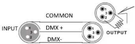
Resistance 120 ohm 1/4w between pin 2 (DMX-) and pin 3 (DMX+) of the last fixture.
CAUTION
Do not allow contact between the common and the
fixture's chassis ground. Grounding the common can cause a ground loop, and your fixture may perform erratically. Test cables with an ohm meter to check correct polarity and to make sure the pins are not grounded or shorted to the shield or each other.
SETTING UP A DMX SERIAL DATA LINK
-
Connect the (male) 3 pin connector side of the DMX cable to the output (female) 3 pin connector of the controller.
-
Connect the end of the cable coming from the controller which will have a (female) 3 pin connector to the input connector of the next fixture consisting of a (male) 3 pin connector.
-
Then, proceed to connect from the output as stated above to the input of the following fixture and so on.
MASTER/SLAVE FIXTURE LINKING
-
Connect the (male) 3 pin connector of the DMX cable to the output (female) 3 pin connector of the first fixture.
-
Connect the end of the cable coming from the first fixture which will have a (female) 3 pin connector to the input connector of the next fixture consisting of a (male) 3 pin connector. Then, proceed to connect from the output as stated above to the input of the following fixture and so on
-
Often, the set up for Master-Slave and Stand-alone operation requires that the first fixture in the chain be initialized for this purpose via either settings in the control panel or DIP-switches. Secondarily, the fixtures that follow may also require a slave setting. Please consult the "Operating Instructions" section in this manual for complete instructions for this type of setup and configuration.
HOW TO CONTROL THE UNIT
Access control panel functions using the four panel buttons located directly underneath the LCD Display.
| Button Function | |
| MENU | press MENU key to enter into the submenus. Press MENU again to leave the sub-menu. If no key is pressed during 30 seconds, the unit will go back to MENU display automatically |
| UP press UP key to increase the displayed values. Keep pressed to increase the values quickly | |
| DOWN | press DOWN key to decrease the displayed values. Keep pressed to decrease the values quickly |
| ENTER | in normal status, this button has no function. In edit mode, press ENTER to enter into the sub-menu |
All functions and operations can be controlled manually on display without DMX controller.
Enter into menu by pressing the MENU button and select the menu item via the up and down keys. Press the ENTER button to confirm your choice. Increase or decrease the value via the UP/DOWN keys. Press ENTER to confirm and exit the menu.
LCD DISPLAY
MODE MENU FUNCTION
| A001~A511 A001~A511 DMX Mode / Jump Strobe | ||
| Au** | Au 1~Au15 Fixed Color, 1~15 means 4 color mixing ( see details below | |
| FF** | FF 1~FF99 Jump Change, Value +, Color change speed + | |
| CC** CC 1~CC99 Gradual Change, Value +, Color change speed + | ||
| EE** EE 1~EE99 Pulse Change, Value +, Color change speed + | ||
| F*** F001~F009 No Strobe | ||
| F010~F255 Value +, Strobe speed + | ||
| AuTo AuTo | Auto Mode, Replay FF**, CC**, EE**, F*** | |
| Soud | Soud | Sound Mode 1 |
| VOL1~VOL9 | Press ENTER "VOL"STROBE, "1~9" means Sound Sensitivity, Value +, Sensitivity + | |
AU \*\* COLOR CHANGE TABLE
| Color | 1 | 2 | 3 | 4 | 5 | 6 | 7 | 8 | 9 | 10 | 11 | 12 | 13 | 14 | 15 |
| R | ON | ON | ON | ON | ON | ON | ON | ON | |||||||
| G | ON | ON | ON | ON | ON | ON | ON | ON | |||||||
| B | ON | ON | ON | ON | ON | ON | ON | ON | |||||||
| W | ON | ON | ON | ON | ON | ON | ON | ON |
Marked with "ON" means the color is ON, blank spaces mean "OFF".
SET DMX ADDRESS CODE:
- Enter into the menu by pressing the MENU button. Select d001 via the up and down keys and press ENTER. Modify the value via the up and down keys. Press ENTER to save and exit, or press the MENU button to exit without saving.
- Enter into menu by pressing the MENU button, select among a variety of operating codes via the UP/DOWN keys. Press ENTER to save and run or MENU to leave the menu and return to the operating modes.
DMX CHANNELS
| CH | VALUE | FUNCTION |
| 1 | 0~255 Master dimmer | |
| 2 | 0~255 R dimmer | |
| 3 | 0~255 G dimmer | |
| 4 | 0~255 B dimmer | |
| 5 | 0~255 W dimmer | |
| 0~255 Strobe function selection | ||
| 6 | 0~99 Par & Strobe Light flash at the same time | |
| 100~199 | Par Light flash | |
| 200~255 | Strobe Light flash | |
| 7 | 0~9 | No Strobe |
| 10~255 | Value +, Strobe speed - | |
| 0~50 Manual Mode, Available from CH1-CH7 | ||
| 51~100 | Jump change, Same as 'FF*' mode, CH6 adjust speed | |
| 8 | 101~150 | Gradual change, Same as 'CC*' mode, CH6 adjust speed |
| 151~200 | Pulse change, Same as 'EE*' mode, CH6 adjust speed | |
| 201~250 | Auto Mode | |
| 251~255 | Sound Mode | |
REMOTE CONTROL
- ON/OFF
- Automatic mode
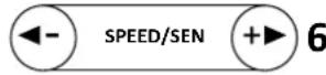
- Music controlled modes
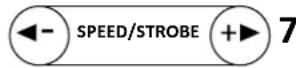
- Strobe mode
- Selection of one of the built-in programs
- Setting of sensitivity and speed of the music controlled mode
- Setting of sensitivity and speed of the strobe mode
IR REMOTE CONTROLLER
Please operate the remote control within a distance of 6m and 30° between the remote and the appliance. Aim the remote at the sensor. Remove all obstacles between the remote and the sensor.
The remote control might not work properly if the sensor is exposed to strong sunshine.
If the remote control doesn't work properly, please check the batteries.
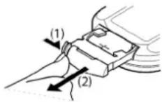
INSTALLING THE BATTERIES IN THE REMOTE CONTROL
- Place the remote face down on a flat surface.
- Push the compartment cover into the direction of the arrow.
- Slide the battery compartment open.
- Remove the old battery and install the new one (CR2032) with the plus (+) symbol facing up.
• Gently slide the battery compartment closed. It locks automatically.


RECOMMENDATIONS FOR BATTERIES

This symbol indicates that used batteries should not be disposed of with household waste but deposed correctly in accordance with your local regulations..
Batteries shall not be exposed to excessive heat such as sunshine, fire or the like.
When the internal batteries are not to be used, remove them to avoid damage caused by battery leakage or corrosion.
ATTENTION: Danger of explosion if battery is incorrectly placed. Only replace by the same or equivalent type.
WARNING : Do not swallow the battery. Danger of chemical burns. Keep new and old batteries out of the reach of children.
If the battery compartment doesn't close properly, stop using the product and keep it out of the reach of children.
If you are in doubt whether the batteries have been swallowed or introduced into any other part of the body, contact immediately a doctor.
FIXTURE CLEANING
The cleaning of internal and external optical lenses and/or mirrors must be carried out periodically to optimize light output. Cleaning frequency depends on the environment in which the fixture operates: damp, smoky or particularly dirty surrounding can cause greater accumulation of dirt on the unit's optics.
Clean with soft cloth using normal glass cleaning fluid. Always dry the parts carefully. Clean the external optics at least every 20 days. Clean the internal optics at least every 30/60 days.
SPECIFICATIONS:
Input voltage: 100-240V\~50/60Hz
Consumption....15W
Channels 8
LED: 3 x 4W RGBW LED 4-in-1; 18x 0.5W white SMD 5730 LED
Function: DMX512, Auto-run, Sound active, remote control
Dimensions 125 x 125 x 125mm
Weight: 600g

Electric products must not be put into household waste. Please bring them to a recycling centre. Ask your local authorities or your dealer about the way to proceed.
PROJECTEUR PAR A LED RGBW 4-EN-1 AVEC STROBOSCOPE A LED SMD
MANUEL D'UTILISATION
EXPLICATION DES SYMBOLES
LED: 3 LED RGBW 4W 4-in-1; 18 LED SMD 0.5W blanches 5730LED
Dimensions: 125 x 125 x 125mm
Poids: 0,6 kg

AU ** FARBWECHSELTABELLE
| Farbe | 1 | 2 | 3 | 4 | 5 | 6 | 7 | 8 | 9 | 10 | 11 | 12 | 13 | 14 | 15 | ||||||||||
| R | ON | ON | ON | ON | ON | ON | ON | ON | |||||||||||||||||
| G | ON | ON | ON | ON | ON | ON | ON | ON | |||||||||||||||||
| B | ON | ON | ON | ON | ON | ON | ON | ON | ON | ||||||||||||||||
| W | ON | ON | ON | ON | ON | ON | ON | ON | ON |
4-IN-1 RGBW LED PAR CAN MET SMD LED STROBE
HANDLEIDING
VERKLARING VAN DE TEKENS
LED: 3 x 4W RGBW LED 4-in-1; 18x 0.5W white SMD 5730 LED
LED: 3 x 4W RGBW LED 4-in-1; 18x 0.5W Blanco SMD 5730 LED
MANUAL DE INSTRUCTIUNI
EXPLICAREA SEMNELOR
| Culoare 1 2 3 4 5 6 7 8 9 10 11 12 13 14 15 | |||||||||||||||
| R | ON | ON | ON | ON | ON | ON | ON | ON | |||||||
| G | ON | ON | ON | ON | ON | ON | ON | ON | |||||||
| B | ON | ON | ON | ON | ON | ON | ON | ON | |||||||
| W | ON | ON | ON | ON | ON | ON | ON | ON | |||||||
LED: 3 x 4W RGBW LED 4-u-1; 18x 0,5W bijela SMD 5730 LED
Funkcija:......DMX512, automatsko pokretanje, aktivan zvuk, daljinski upravljač
Dimenzije: 125 × 125 × 125
Težina: 0,6kg

Električni proizvodi ne smiju se odlagati u kućni otpad. Molimo vas da ih odnesete u centar za reciklažu. Raspitajte se kod lokalnih vlasti ili kod prodavača o načinu na koji trebate postupiti..
PAR CAN LED RGBW 4 IN 1 CON STROBO LED SMD
| Colore | 1 | 2 | 3 | 4 | 5 | 6 | 7 | 8 | 9 | 10 | 11 | 12 | 13 | 14 | 15 |
| R | ON | ON | ON | ON | ON | ON | ON | ON | |||||||
| G | ON | ON | ON | ON | ON | ON | ON | ON | |||||||
| B | ON | ON | ON | ON | ON | ON | ON | ON | |||||||
| W | ON | ON | ON | ON | ON | ON | ON | ON |
4-IN-1 RGBW LED PAR CAN WITH SMD LED STROBE
MANUAL DE INSTRUÇÕES
Resistance 120 ohm 1/4w between pin 2 (DMX-) and pin 3 (DMX+) of the last fixture.
CUIDADO

Download the manual in other languages

Any question or problem?
Contact us via facebook

IBIZALIGHTSOUND
Follow us on Instagram

Assembled in PRC • Designed by LOTRONIC S.A. •
Rue F. Englert 17·Bt 2·B-1480 Tubize
https://ibizashop.eu/

- 4-IN-1 RGBW LED PAR CAN
- WITH SMD LED STROBE
- Ref.
- PAR-MINI-STR
- MANUAL
- 4-IN-1 RGBW LED PAR CAN WITH SMD LED STROBE
- INSTRUCTION MANUAL
- EXPLANATION OF SYMBOLS ON THE SILKSCREEN
- CAUTION DO NOT OPEN THE HOUSING SHOCK HAZARD
- IMPORTANT SAFETY INSTRUCTIONS AND DANGER WARNINGS
- INSTALLATION
- FIXTURE LINKING
- CABLE CONNECTORS
- DMX CONNECTOR CONFIGURATION
- CAUTION
- SETTING UP A DMX SERIAL DATA LINK
- MASTER/SLAVE FIXTURE LINKING
- HOW TO CONTROL THE UNIT
- LCD DISPLAY
- AU \*\* COLOR CHANGE TABLE
- SET DMX ADDRESS CODE:
- DMX CHANNELS
- REMOTE CONTROL
- IR REMOTE CONTROLLER
- INSTALLING THE BATTERIES IN THE REMOTE CONTROL
- RECOMMENDATIONS FOR BATTERIES
- FIXTURE CLEANING
- SPECIFICATIONS:
- PROJECTEUR PAR A LED RGBW 4-EN-1 AVEC STROBOSCOPE A LED SMD
- MANUEL D'UTILISATION
- EXPLICATION DES SYMBOLES
- 4-IN-1 RGBW LED PAR CAN MET SMD LED STROBE
- HANDLEIDING
- VERKLARING VAN DE TEKENS
- MANUAL DE INSTRUCTIUNI
- EXPLICAREA SEMNELOR
- PAR CAN LED RGBW 4 IN 1 CON STROBO LED SMD
- MANUAL DE INSTRUÇÕES
- CUIDADO
Brand : IBIZA SOUND
Model : PAR-MINI-STR
Category : Toys