
UB002G - Blower MAKITA - Free user manual and instructions
Find the device manual for free UB002G MAKITA in PDF.

| Product type | Cordless blower / vacuum |
| Brand | Makita |
| Model | UB002G |
| Total length | 516 mm (with nozzle and battery BL4040) |
| Net weight | 1.3 kg (without accessories); 2.0 – 3.5 kg (depending on accessories and battery) |
| Rated voltage | 36 V – 40 V DC max. |
| Airflow (without nozzles) | 0 – 3.6 m³/min |
| Air speed (average) | 0 – 81 m/s |
| Air speed (max.) | 0 – 99 m/s |
| Sound pressure level (blowing) | 84 dB(A) (EN62841-1) |
| Sound power level (blowing) | 92 dB(A) (EN62841-1) |
| Sound pressure level (vacuuming) | 87 dB(A) (EN62841-1) |
| Vibration (blowing/vacuuming) | ≤ 2.5 m/s² |
| Compatible batteries | BL4020, BL4025, BL4040, BL4040F, BL4050F, BL4080F (recommended: BL4020, BL4025, BL4040, BL4040F) |
| Compatible chargers | DC40RA, DC40RB, DC40RC, DC40WA, BCC01, BCC02 |
| Main functions | Blowing and vacuuming |
| Speed adjustment | 3-position lever (1 low, 2 medium, 3 high) |
| Included accessories | Nozzle (blowing); other optional accessories (garden nozzle, dust bag, etc.) |
| Maintenance and cleaning | Wipe with a dry or soapy water-dampened cloth; do not use solvents |
| Safety | Safety goggles, ear protection, non-slip shoes recommended |
| Warranty | Makita warranty voided if using non-original batteries |
Frequently Asked Questions - UB002G MAKITA
User questions about UB002G MAKITA
0 question about this device. Answer the ones you know or ask your own.
Ask a new question about this device
Download the instructions for your Blower in PDF format for free! Find your manual UB002G - MAKITA and take your electronic device back in hand. On this page are published all the documents necessary for the use of your device. UB002G by MAKITA.
USER MANUAL UB002G MAKITA
natural_image
Line drawing of a mechanical device with a long cylindrical shaft and circular housing (no text or symbols)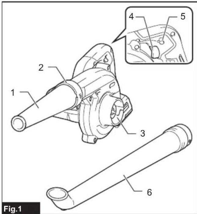
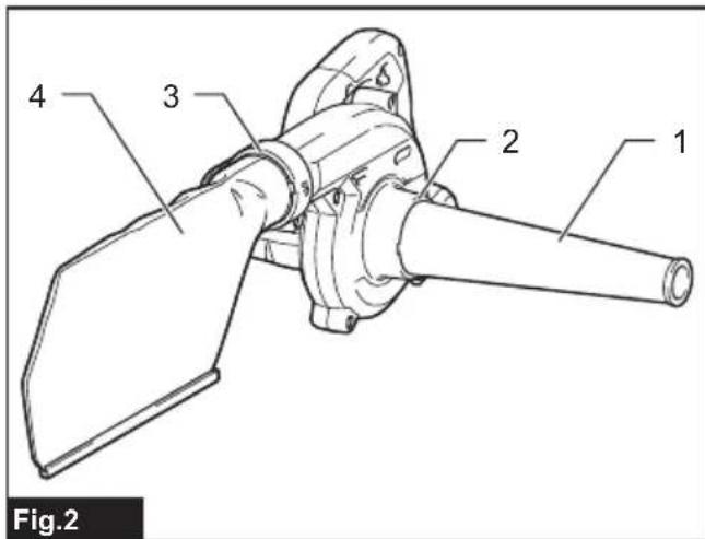
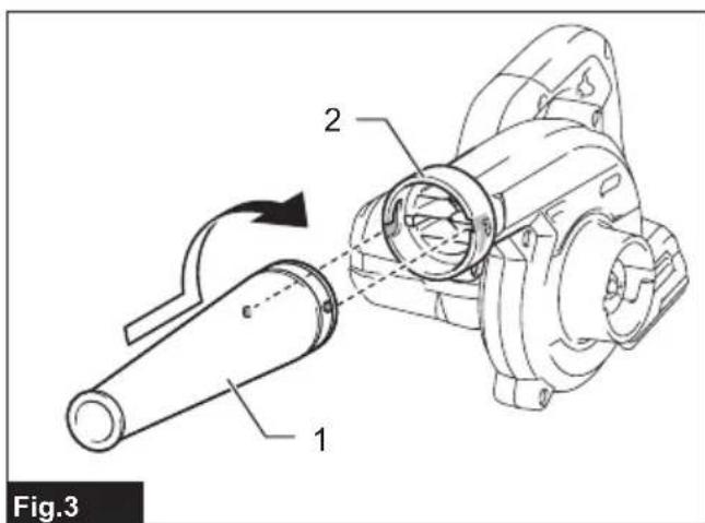
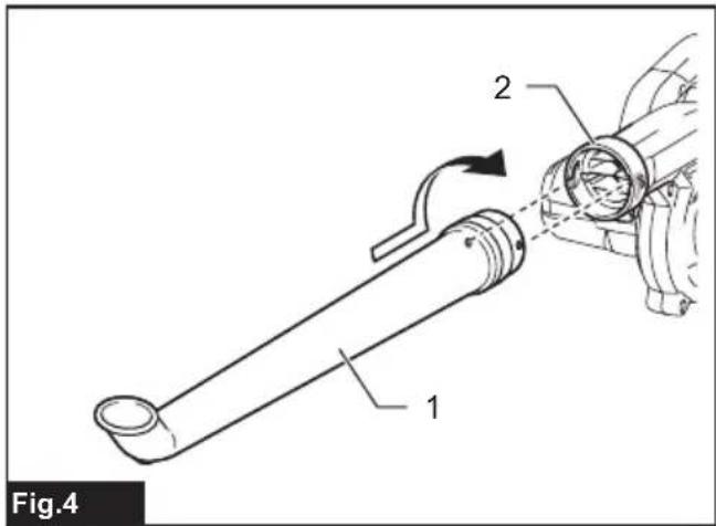
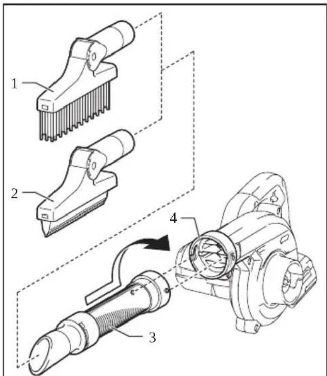
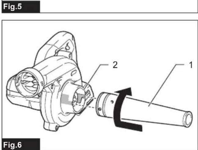
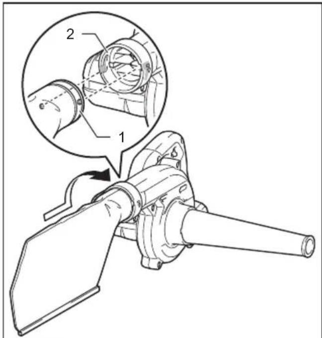
Fig.7
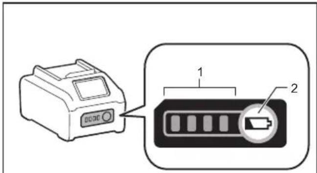
Fig.10
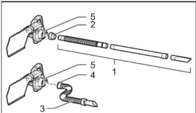
Fig.8
natural_image
Two identical line drawings of a printer with labeled parts, shown from different angles (no text or symbols present)Fig.9
natural_image
Line drawing of a person using a handheld device (no text or symbols)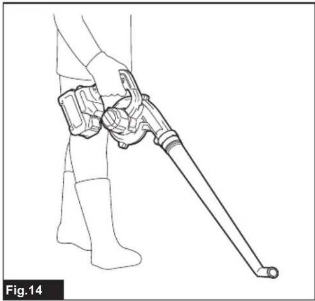
natural_image
Line drawing of a person holding a long-handled tool, no text or symbols present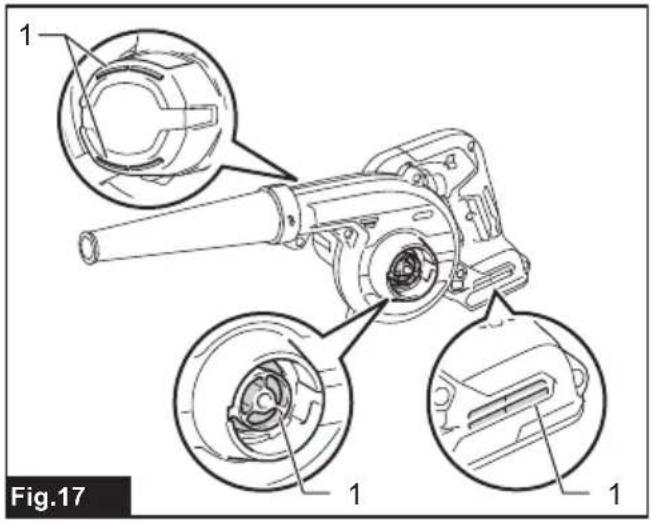
natural_image
Line drawing of a person using a manual power tool on a workbench (no text or symbols)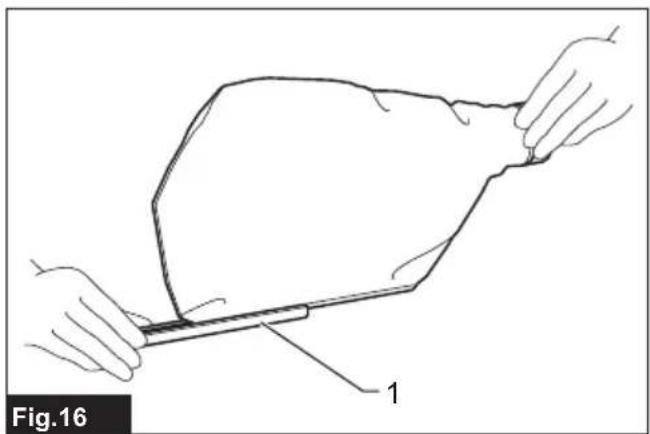
natural_image
Line drawing of a hand holding a tool over a flat object, labeled 'Fig.16' (no text or symbols on the diagram itself)SPECIFICATIONS
| Model: UB002G | ||
| Capacities Air volume | ^1 | 0 - 3.6 m^3/min |
| Air speed (average) ^2 | 0 - 81 m/s | |
| Air speed (max.) ^2 | 0 - 99 m/s | |
| Overall length ^3 | 516 mm | |
| Rated voltage D.C. 36 V - 40 V max | ||
| Net weight | ^4 | 1.3 kg |
| ^5 | 2.0 - 3.5 kg | |
^1 Without nozzles
^2 With nozzle
^*3 With nozzle and battery cartridge BL4040, and without dust bag
*4 Weight without any optional accessories and battery cartridge(s)
^5 The weight may differ depending on the attachment(s), including the battery cartridge. The lightest and heaviest combination are shown in the table.
- Due to our continuing program of research and development, the specifications herein are subject to change without notice.
- Specifications may differ from country to country.
Applicable battery cartridge and charger
| Battery cartridge BL4020* / BL4025* / BL4040* / BL4040F* / BL4050F / BL4080F | *: Recommended battery |
| Charger DC40RA / DC40RB / DC40RC / DC40WA / BCC01 / BCC02 |
- Some of the battery cartridges and chargers listed above may not be available depending on your region of residence.

WARNING: Only use the battery cartridges and chargers listed above. Use of any other battery cartridges and chargers may cause injury and/or fire.
Symbols
The followings show the symbols which may be used for the equipment. Be sure that you understand their meaning before use.


Ni-MH Li-ion
A representative battery applicable to this product.
Only for EU countries
Due to the presence of hazardous components in the equipment, waste electrical and electronic equipment, accumulators and batteries may have a negative impact on the environment and human health. Do not dispose of electrical and electronic appliances or batteries with household waste!
In accordance with the European Directive on waste electrical and electronic equipment and on accumulators and batteries and waste accumulators and batteries, as well as their adaptation to national law, waste electrical equipment, batteries and accumulators should be stored separately and delivered to a separate collection point for municipal waste, operating in accordance with the regulations on environmental protection.
This is indicated by the symbol of the crossed-out wheeled bin placed on the equipment.

Guaranteed sound power level according to EU Outdoor Noise Directive.

Sound power level according to Australia NSW Noise Control Regulation.
Intended use
The machine is intended for blowing and vacuuming.
Noise
The typical A-weighted noise level determined according to EN62841-1:
With nozzle
Work mode: operation without load (blowing)
Sound pressure level ( L_pA ): 84 dB (A)
Sound power level ( L_WA ): 92 dB (A)
Uncertainty (K): 3 dB (A)
With nozzle
Work mode: operation without load (vacuuming)
Sound pressure level ( L_pA ): 87 dB(A)
Sound power level ( L_WA ): 95 dB (A)
Uncertainty (K): 3 dB(A)
The typical A-weighted noise level determined according to EN IEC 62841-4-6:
With garden nozzle
Work mode: operation without load (blowing)
Sound pressure level ( L_pA ): 81 dB (A)
Uncertainty (K) : 3 dB(A)
Sound power level ( L_WA ): 91 dB (A)
Uncertainty (K): 2.0 dB (A)
NOTE: The declared noise emission value(s) has been measured in accordance with a standard test method and may be used for comparing one tool with another.
NOTE: The declared noise emission value(s) may also be used in a preliminary assessment of exposure.
WARNING: Wear ear protection.
⚠ WARNING: The noise emission during actual use of the power tool can differ from the declared value(s) depending on the ways in which the tool is used especially what kind of workpiece is processed.
⚠ WARNING: Be sure to identify safety measures to protect the operator that are based on an estimation of exposure in the actual conditions of use (taking account of all parts of the operating cycle such as the times when the tool is switched off and when it is running idle in addition to the trigger time).
Vibration
The vibration total value (tri-axial vector sum) determined according to EN62841-1:
With nozzle
Work mode: operation without load (blowing)
Vibration emission ( a_h ): 2.5 m/s ^2 or less
Uncertainty (K) : 1.5 m/s ^4
With nozzle
Work mode: operation without load (vacuuming)
Vibration emission (ah): 2.5 m/s ^2 or less
Uncertainty (K) : 1.5 m/s ^2
The vibration total value (tri-axial vector sum) determined according to EN IEC 62841-4-6:
With garden nozzle
Work mode: operation without load (blowing)
Vibration emission (ah): 2.5 m/s ^2 or less
Uncertainty (K) : 1.5 m/s²
NOTE: The declared vibration total value(s) has been measured in accordance with a standard test method and may be used for comparing one tool with another.
NOTE: The declared vibration total value(s) may also be used in a preliminary assessment of exposure.
⚠ WARNING: The vibration emission during actual use of the power tool can differ from the declared value(s) depending on the ways in which the tool is used especially what kind of workpiece is processed.
WARNING: Be sure to identify safety measures to protect the operator that are based on an estimation of exposure in the actual conditions of use (taking account of all parts of the operating cycle such as the times when the tool is switched off and when it is running idle in addition to the trigger time).
Declarations of Conformity
For European countries only
The Declarations of conformity are included in Annex A to this instruction manual.
SAFETY WARNINGS
General power tool safety warnings
⚠ WARNING Read all safety warnings, instructions, illustrations and specifications provided with this power tool. Failure to follow all instructions listed below may result in electric shock, fire and/or serious injury.
Save all warnings and instructions for future reference.
The term "power tool" in the warnings refers to your mains-operated (corded) power tool or battery-operated (cordless) power tool.
Cordless garden blower/vacuum safety warnings
-
Do not use the machine in bad weather conditions, especially when there is a risk of lightning. This decreases the risk of being struck by lightning.
-
Check the debris collector frequently for wear or deterioration. A worn or damaged debris collector may increase the risk of personal injury.
-
Wear eye protection and ear protection. Adequate protective equipment will reduce the risk of personal injury.
-
While operating the machine, always wear non-slip and protective footwear. Do not operate the machine when barefoot or wearing open sandals. This reduces the risk of injury to the feet.
-
Do not wear loose fitting clothing or articles such as scarves, strings, chains, ties, etc., that could get drawn into the air inlets. Tie back or cover long hair to make sure it does not get drawn into the air inlets. If any of these items are drawn into the air inlets, it can increase the risk of personal injury.
-
Keep bystanders away while operating the machine. Thrown debris can increase the risk of personal injury.
-
Do not use in vacuum mode without the debris collector in place. Thrown objects can increase the risk of personal injury.
-
Never point the blower nozzle in the direction of people or pets or in the direction of windows. Use extra caution when blowing debris near solid objects, such as trees, automobiles and walls that can cause debris to ricochet. Thrown objects can damage property and increase the risk of personal injury.
-
Do not use the machine to pick up or blow anything that is burning or smoking, such as cigarettes, matches or hot ashes. These ignition sources may increase the risk of fire.
-
Do not vacuum water or other liquids or immerse any part of the machine in liquid. Water entering the machine may increase the risk of electric shock.
-
Do not vacuum stones, gravel, metal or broken glass. The fan wheel can get damaged and may increase the risk of personal injury.
-
Do not touch the fan while still in motion. Turn off the machine and wait until the fan stops before removing any part that may give access to the fan. This reduces the risk of injury from moving parts.
-
When clearing jammed material or servicing the machine, make sure the power switch is off. Unexpected starting of the machine while clearing jammed material or servicing may result in serious personal injury.
-
Incoming foreign substance may block the air channels and laden air flows. Remove any obstacles in the air path if the blowing/vacuuming performance is being affected.
-
Always wear gloves during operation. Avoid operating the machine with your bare hands. This reduces the risk of injury to the hands and fingers.
-
Use this machine at ground level, not on ladders or any unstable support.
-
When the machine strikes a hard object or if there appears to be excessive vibration, inspect the machine for damage.
-
Always make sure that the ventilation openings are kept clear of debris.
-
Clean the machine before storage.
SAVE THESE INSTRUCTIONS.
WARNING: DO NOT let comfort or familiarity with product (gained from repeated use) replace strict adherence to safety rules for the subject product.
MISUSE or failure to follow the safety rules stated in this instruction manual may cause serious personal injury.
Important safety instructions for battery cartridge
-
Before using battery cartridge, read all instructions and cautionary markings on (1) battery charger, (2) battery, and (3) product using battery.
-
Do not disassemble or tamper with the battery cartridge. It may result in a fire, excessive heat, or explosion.
-
If operating time has become excessively shorter, stop operating immediately. It may result in a risk of overheating, possible burns and even an explosion.
-
If electrolyte gets into your eyes, rinse them out with clear water and seek medical attention right away. It may result in loss of your eyesight.
-
Do not short the battery cartridge:
(1) Do not touch the terminals with any conductive material.
(2) Avoid storing battery cartridge in a container with other metal objects such as nails, coins, etc.
(3) Do not expose battery cartridge to water or rain.
A battery short can cause a large current flow, overheating, possible burns and even a breakdown.
-
Do not store and use the tool and battery cartridge in locations where the temperature may reach or exceed 50 °C (122 °F).
-
Do not incinerate the battery cartridge even if it is severely damaged or is completely worn out. The battery cartridge can explode in a fire.
-
Do not nail, cut, crush, throw, drop the battery cartridge, or hit against a hard object to the battery cartridge. Such conduct may result in a fire, excessive heat, or explosion.
-
Do not use a damaged battery.
-
The contained lithium-ion batteries are subject to the Dangerous Goods Legislation requirements.
For commercial transports e.g. by third parties, forwarding agents, special requirement on packaging and labeling must be observed.
For preparation of the item being shipped, consulting an expert for hazardous material is required. Please also observe possibly more detailed national regulations.
Tape or mask off open contacts and pack up the battery in such a manner that it cannot move around in the packaging.
- When disposing the battery cartridge, remove it from the tool and dispose of it in a safe place. Follow your local regulations relating to disposal of battery.
- Use the batteries only with the products specified by Makita. Installing the batteries to non-compliant products may result in a fire, excessive heat, explosion, or leak of electrolyte.
- If the tool is not used for a long period of time, the battery must be removed from the tool.
- During and after use, the battery cartridge may take on heat which can cause burns or low temperature burns. Pay attention to the handling of hot battery cartridges.
- Do not touch the terminal of the tool immediately after use as it may get hot enough to cause burns.
- Do not allow chips, dust, or soil stuck into the terminals, holes, and grooves of the battery cartridge. It may cause heating, catching fire, burst and malfunction of the tool or battery cartridge, resulting in burns or personal injury.
- Unless the tool supports the use near high-voltage electrical power lines, do not use the battery cartridge near high-voltage electrical power lines. It may result in a malfunction or breakdown of the tool or battery cartridge.
- Keep the battery away from children.
SAVE THESE INSTRUCTIONS.
CAUTION: Only use genuine Makita batteries.
Use of non-genuine Makita batteries, or batteries that have been altered, may result in the battery bursting causing fires, personal injury and damage. It will also void the Makita warranty for the Makita tool and charger.
Tips for maintaining maximum battery life
- Charge the battery cartridge before completely discharged. Always stop tool operation and charge the battery cartridge when you notice less tool power.
- Never recharge a fully charged battery cartridge. Overcharging shortens the battery service life.
- Charge the battery cartridge with room temperature at 10 °C - 40 °C (50 °F - 104 °F). Let a hot battery cartridge cool down before charging it.
- When not using the battery cartridge, remove it from the tool or the charger.
- Charge the battery cartridge if you do not use it for a long period (more than six months).
PARTS DESCRIPTION
Blowing components
▶ Fig.1
| 1 Nozzle 2 Blower outlet | |||
| 3 Suction inlet 4 Switch trigger | |||
| 5 | Speed adjusting lever | 6 | Garden nozzle * |
* Optional accessory
Vacuuming components
▶ Fig.2
| 1 N | bzzle 2 Suction inlet | ||
| 3 B | ower outlet 4 Dust bag * |
* Optional accessory
ASSEMBLY
CAUTION: Always be sure that the machine is switched off and the battery cartridge is removed before carrying out any work on the machine.
Blower assembly
Installing and removing nozzle
Align the protrusions on the nozzle with the grooves on the blowing outlet. Insert the nozzle into the outlet opening. Then turn the nozzle to lock it into place.
▶ Fig.3: 1. Nozzle 2. Blower outlet
To remove the nozzle, perform the installation procedure in reverse.
Installing and removing garden nozzle
Optional accessory
Align the protrusions on the garden nozzle with the grooves on the blowing outlet. Insert the garden nozzle into the outlet opening. Then turn the garden nozzle to lock it into place.
▶ Fig.4: 1. Garden nozzle 2. Blower outlet
To remove the garden nozzle, perform the installation procedure in reverse.
Installing and removing brush/wiper nozzles
Optional accessory
Attach the brush nozzle or wiper nozzle to an expandable flexible hose. Insert the end joint of the expandable hose into the blower outlet, and then turn the joint to lock the hose into place.
▶ Fig.5: 1. Brush nozzle 2. Wiper nozzle 3. Expandable flexible hose 4. Blower outlet
To remove the set of nozzle and hose, perform the installation procedure in reverse.
Installing and removing long nozzle
Optional accessory
Install the long nozzle in the same way as the nozzle. To remove the long nozzle, perform the installation procedure in reverse.
Installing and removing tapered nozzle
Optional accessory
Attach the tapered nozzle to the nozzle first, and then install the nozzle to the blower. To remove the tapered nozzle, perform the installation procedure in reverse.
Vacuum assembly
Installing and removing nozzle
Align the protrusions on the nozzle with the grooves on the suction inlet. Insert the nozzle into the inlet opening. Then turn the nozzle to lock it into place.
▶ Fig.6: 1. Nozzle 2. Suction inlet
To remove the nozzle, perform the installation procedure in reverse.
Installing and removing dust bag
Optional accessory
Align the protrusions on the dust bag inlet with the grooves on the blower outlet. Insert the inlet of the dust bag into the blower outlet opening. Then turn the dust bag inlet to lock the dust bag into place.
▶ Fig.7: 1. Dust bag inlet 2. Blower outlet
To remove the dust bag, perform the installation procedure in reverse.
Installing and removing flexible hose sets
Optional accessory
Select a flexible hose set suitable for your application. Assemble a set of flexible hose, pipe and nozzle together, then attach it to the suction inlet of the blower using the joint in the same way as the nozzle assembly. For an expandable flexible hose set, insert the end joint of the hose into the suction inlet of the blower, and then turn the joint to lock the hose into place.
▶ Fig.8: 1. Set of flexible hose, pipe, and nozzle
-
Joint 3. Expandable flexible hose set
-
End joint 5. Suction inlet
To remove the flexible hose sets, perform the installation procedure in reverse.
FUNCTIONAL DESCRIPTION
CAUTION: Always be sure that the machine is switched off and the battery cartridge is removed before adjusting or checking function on the machine.
Installing or removing battery cartridge
CAUTION: Always switch off the machine before installing or removing of the battery cartridge.
CAUTION: Hold the machine and the battery cartridge firmly when installing or removing battery cartridge. Failure to hold the machine and the battery cartridge firmly may cause them to slip off your hands and result in damage to the machine and battery cartridge and a personal injury.
CAUTION: Always install the battery cartridge fully until the red indicator cannot be seen. If not, it may accidentally fall out of the machine, causing injury to you or someone around you.
⚠️ CAUTION: Do not install the battery cartridge forcibly. If the cartridge does not slide in easily, it is not being inserted correctly.
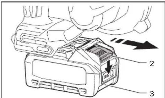
To install the battery cartridge, align the tongue on the battery cartridge with the groove in the housing and slip it into place. Insert it all the way until it locks in place with a little click. If you can see the red indicator as shown in the figure, it is not locked completely.
To remove the battery cartridge, slide it from the machine while sliding the button on the front of the cartridge.
▶ Fig.9: 1. Red indicator 2. Button 3. Battery cartridge
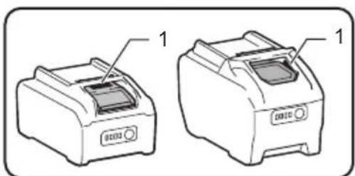
Indicating the remaining battery capacity
Press the check button on the battery cartridge to indicate the remaining battery capacity. The indicator lamps light up for a few seconds.
▶ Fig.10: 1. Indicator lamps 2. Check button
| Indicator lamps Remaining | capacity | ||
| Lighted Off | Blinking | ||
| 75% to 100% | |||
| 50% to 75% | |||
| 25% to 50% | |||
| 0% to 25% | |||
 | Charge the battery. | ||
  | The battery may have malfunctioned. | ||
NOTE: Depending on the conditions of use and the ambient temperature, the indication may differ slightly from the actual capacity.
NOTE: The first (far left) indicator lamp will blink when the battery protection system works.
Machine/battery protection system
The machine is equipped with a machine/battery protection system. This system automatically cuts off power to the motor to extend machine and battery life. The machine will automatically stop during operation if the machine or battery is placed under one of the following conditions:
Overload protection
When the machine or battery is operated in a manner that causes it to draw an abnormally high current, the machine automatically stops. In this situation, switch off the machine and stop the application that caused the machine to become overloaded. Then switch on the machine to restart.
Overheat protection
When the machine or battery is overheated, the machine stops automatically. In this case, let the machine and battery cool before turning the machine on again.
Overdischarge protection
When the battery capacity is not enough, the machine stops automatically. In this case, remove the battery from the machine and charge the battery.
Protections against other causes
Protection system is also designed for other causes that could damage the machine and allows the machine to stop automatically. Take all the following steps to clear the causes, when the machine has been brought to a temporary halt or stop in operation.
- Turn the machine off, and then turn it on again to restart.
- Charge the battery(ies) or replace it/them with recharged battery(ies).
- Let the machine and battery(ies) cool down.
If no improvement can be found by restoring protection system, then contact your local Makita Service Center.
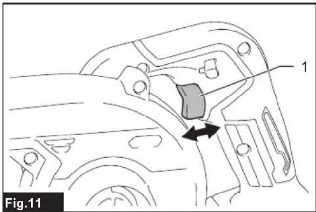
Switch action
WARNING: Before installing the battery cartridge into the machine, always check to see that the switch trigger actuates properly and returns to the "OFF" position when released.
Pull the switch trigger to start the machine. The speed increases as you squeeze the switch trigger harder. Release the switch trigger to stop.
▶ Fig.11: 1. Switch trigger
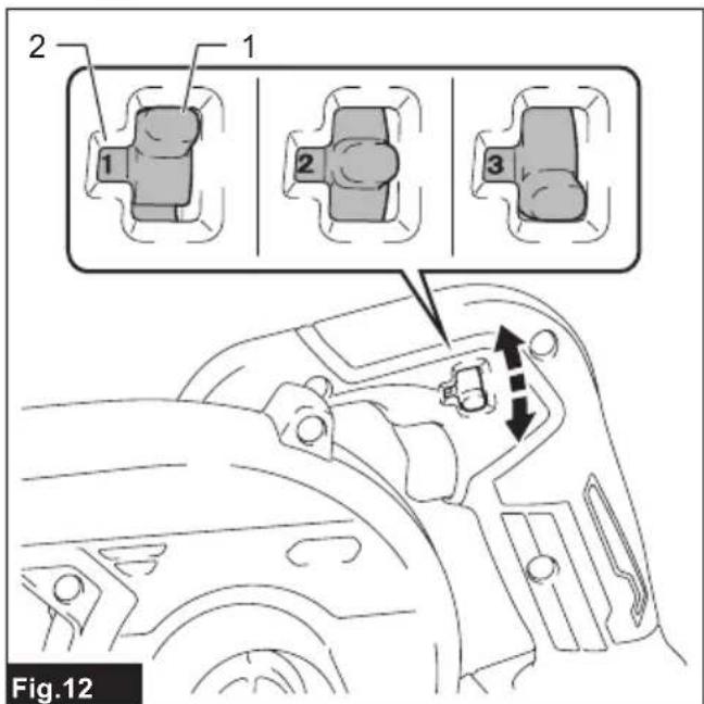
Speed adjusting lever
The speed can be changed by moving the speed adjusting lever to a given number setting from 1 to 3. Higher speed is obtained when you lower the lever to display the number "3" on the speed indicator window. Push the lever up to display the number "1" for lower speed.
Refer to the speed settings table as follows. Be sure that the speed adjusting lever is set to the correct position before operation.
▶ Fig.12: 1. Speed adjusting lever 2. Speed indicator window
Speed settings table
| Number Speed | |
| 3 High | |
| 2 Medium | |
| 1 Low |
NOTICE: When moving the speed adjusting lever, be sure to completely release the switch trigger. Otherwise, the machine may be damaged.
Accidental re-start preventive function
Even if you install the battery cartridge while pulling the switch trigger, the machine does not start. To start the machine, first release the switch trigger, and then pull the switch trigger again.
OPERATION
CAUTION: Do not place the machine on the ground while it is switched on. Sand or dust may enter from suction inlet and cause a malfunction or personal injury.
Blowing operation
CAUTION: When performing the blower operation, be sure to remove the dust bag from the machine, and attach the nozzle in place for blowing.
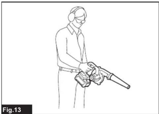
Hold the machine firmly with a hand and perform the blowing operation by moving it around slowly. When blowing
around building, big stone or vehicle, direct the nozzle away from them. When performing an operation in a corner, start from the corner and then move to wide area.
Blowing with nozzle
▶ Fig.13
Blowing with garden nozzle (optional accessory)
▶ Fig.14
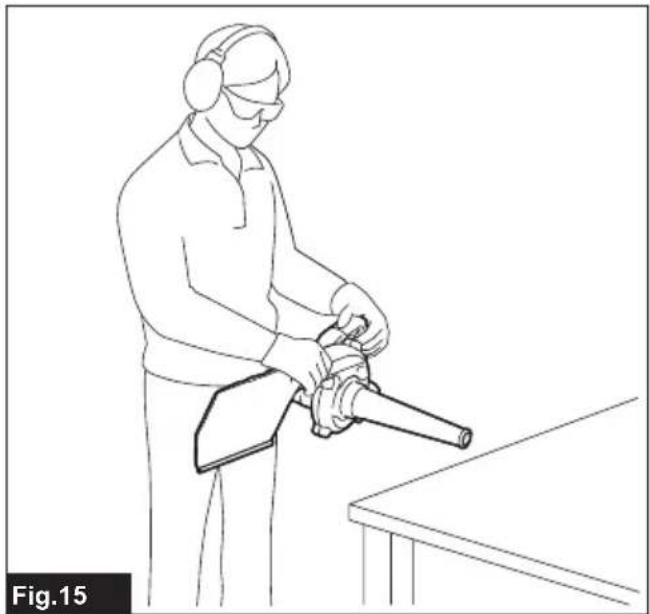
Vacuuming operation
⚠️CAUTION: When performing the vacuuming operation, be sure to attach the dust bag and nozzle in place to the machine.
⚠️CAUTION: Check the dust bag frequently for wear or deterioration.
⚠️CAUTION: Be sure to fasten the fastener of the dust bag before operating the machine.
⚠️CAUTION: Always switch off the machine before opening or fastening the fastener of the dust bag.
NOTICE: When performing the vacuuming operation, do not use the garden nozzle. The materials sucked may be clogged, and cause a malfunction of the machine.
NOTICE: Do not allow wet materials, such as wet leaves, and foreign materials, such as large wood chips, metals, glass, pebbles, etc., to be sucked into the machine. Otherwise, a malfunction may occur.
NOTICE: Empty the dust bag before it becomes full. Otherwise, a malfunction may occur.
* Dust bag and garden nozzle are available as optional accessories.
Hold the machine with both hands. While operating the machine, adjust the switch trigger so that the suction force is appropriate for the work location and conditions.
▶ Fig.15
Empty the dust bag before it becomes full by removing the dust bag from the machine, and then removing the fastener.
⚠️ CAUTION: Always be sure that the machine is switched off and the battery cartridge is removed before attempting to perform inspection or maintenance.
To maintain product SAFETY and RELIABILITY, repairs, any other maintenance or adjustment should be performed by Makita Authorized or Factory Service Centers, always using Makita replacement parts.
Cleaning the machine
Clean the machine by wiping off dust with a dry cloth or one dipped in soapy water and wrung out.
NOTICE: Never use gasoline, benzine, thinner, alcohol or the like. Discoloration, deformation or cracks may result.
Remove dust or dirt from the suction inlets.
▶ Fig.17: 1. Suction inlet
TROUBLESHOOTING
Before asking for repairs, conduct your own inspection first. If you find a problem that is not explained in the manual, do not attempt to dismantle the machine. Instead, ask Makita Authorized Service Centers, always using Makita replacement parts for repairs.
| State of abnormality Probable cause | (malfunction) Remedy | |
| Motor does not run. Battery cartridge is | not installed. Install the battery cartridge. | |
| Battery problem (under voltage) Recharge | the battery. If recharging is not effective, replace battery. | |
| The drive system does not work correctly. | Ask your local authorized service center for repair. | |
| Motor stops running after a little use. | Battery's charge level is low. | Recharge the battery. If recharging is not effective, replace battery. |
| Overheating. Stop using the machine to allow it to cool down. | ||
| The machine does not reach the maximum speed. | Battery is installed improperly. Install the | battery cartridge as described in this manual. |
| Battery power is dropping. Recharge the | battery. If recharging is not effective, replace battery. | |
| The drive system does not work correctly. | Ask your local authorized service center for repair. | |
| Abnormal vibration: ⇒ stop the machine immediately! | The drive system does not work correctly. | Ask your local authorized service center for repair. |
| Motor cannot stop: ⇒ Remove the battery immediately! | Electric or electronic malfunction. Remove | the battery and ask your local authorized service center for repair. |
OPTIONAL ACCESSORIES
⚠️CAUTION: These accessories or attachments are recommended for use with your Makita product specified in this manual. The use of any other accessories or attachments might present a risk of injury to persons. Only use accessory or attachment for its stated purpose.
If you need any assistance for more details regarding these accessories, ask your local Makita Service Center.
- Nozzle
- Garden nozzle
- Dust bag
- Long nozzle
- Brush nozzle
- Wiper nozzle
- Tapered nozzle set
- Flexible hose set
- Makita genuine battery and charger
NOTE: Some items in the list may be included in the product package as standard accessories. They may differ from country to country.
SPÉCIFICATIONS
▶ Fig.11: 1. Gâchette
Incertezza (K): 2,0 dB (A)
⚠ WAARSCHUWING: Draag gehoorbescherming.
VEILIGHEIDSWAAR- SCHUWINGEN
OPTIONELE ACCESSOIRES

- Symbols
- Intended use
- Noise
- With nozzle
- With garden nozzle
- Vibration
- Declarations of Conformity
- For European countries only
- SAFETY WARNINGS
- General power tool safety warnings
- Save all warnings and instructions for future reference.
- Cordless garden blower/vacuum safety warnings
- SAVE THESE INSTRUCTIONS.
- Important safety instructions for battery cartridge
- Tips for maintaining maximum battery life
- PARTS DESCRIPTION
- ASSEMBLY
- Blower assembly
- Installing and removing nozzle
- Installing and removing garden nozzle
- Optional accessory
- Installing and removing brush/wiper nozzles
- Installing and removing long nozzle
- Installing and removing tapered nozzle
- Vacuum assembly
- Installing and removing dust bag
- Installing and removing flexible hose sets
- FUNCTIONAL DESCRIPTION
- Installing or removing battery cartridge
- Indicating the remaining battery capacity
- Machine/battery protection system
- Overload protection
- Overheat protection
- Overdischarge protection
- Protections against other causes
- Switch action
- Speed adjusting lever
- Accidental re-start preventive function
- OPERATION
- Blowing operation
- Blowing with nozzle
- Vacuuming operation
- Cleaning the machine
- TROUBLESHOOTING
- OPTIONAL ACCESSORIES
- ⚠ WAARSCHUWING: Draag gehoorbescherming.
- VEILIGHEIDSWAAR- SCHUWINGEN
- OPTIONELE ACCESSOIRES
Brand : MAKITA
Model : UB002G
Category : Blower