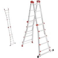
M80 - Ladder HAILO - Free user manual and instructions
Find the device manual for free M80 HAILO in PDF.


| Product Type | Single-hinge articulated ladder |
| Brand | HAILO |
| Model | M80 |
| References | 7512-xxx (4x3 rungs), 7516-xxx (4x4), 7520-xxx (4x5), 7524-xxx (4x6) |
| Use | Professional and non-professional |
| Standard | EN 131-4 |
| Maximum load capacity | 150 kg |
| Main material | Aluminium |
| Weight | Depending on model, approx. 8 to 15 kg (see identification label) |
| Working dimensions (height) | Varies according to configuration and number of rungs (see table on pages 142-143 of the manual) |
| Possible configurations | Bilateral ladder, leaning ladder (single or sliding), staircase ladder |
| Safety mechanism | Safety hinge with lockable positions and lateral locking handles |
| Crossbar | Mandatory on models 7516, 7520, 7524 (mount before use) |
| Maintenance | Clean with a dry, clean cloth; do not use abrasive or aggressive products |
| Storage | Away from humidity, high temperatures and bad weather; store unfolded and locked |
| Transport | Retract the uprights and fold the ladder; secure firmly (e.g., on roof rack) |
| Spare parts | Contact HAILO: Daimlerstr. 8, 35708 Haiger, Germany - Tel. +49 (0) 2773 82-0 |
| Warranty | Void if unauthorized modification by the manufacturer |
Frequently Asked Questions - M80 HAILO
User questions about M80 HAILO
0 question about this device. Answer the ones you know or ask your own.
Ask a new question about this device
Download the instructions for your Ladder in PDF format for free! Find your manual M80 - HAILO and take your electronic device back in hand. On this page are published all the documents necessary for the use of your device. M80 by HAILO.
USER MANUAL M80 HAILO
natural_image
Three identical metal ladder structures arranged vertically on a platform, shown from different angles (no text or symbols)Gebrauchsanleitung
Eingelenkleitern
Instructions for use
Single-hinge joint ladders
Mode d'emploi
Échelles articulées
-Stehleiter A = Höhe
natural_image
Diagram of a ladder leaning against a surface with labeled points A and B (no text or symbols beyond labels)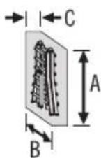

![3. "click" [C-3]](/content/2026/04/717002/images/95c344d7d461da289336e0e907c5f2454d1ac0955c2f0a38762250e19f864eec.jpg)
![[D] [A] [D] [A]](/content/2026/04/717002/images/a693867cc614c7227b893c555b53031b2169506ed76685824cad1be3e3e9e353.jpg)
![1. [D] [A] 3. "click"](/content/2026/04/717002/images/d466c15d1e0740d9f23e20b91088e9bf54a545ef5d6eac8e4fdaf3ff5aadd71c.jpg)
natural_image
Illustration showing a tree with ladder and a house with ladder, separated by a diagonal hatched background (no text or symbols)de
10. Gebrauchsdauer
Single-hinge joint ladder
Item no. 7512-xxx (4 x 3 rungs)
7516-xxx (4 x 4 rungs)
7520-xxx (4 x 5 rungs)
7524-xxx ( 4 x 6 rungs )
Table of Contents
- Introduction and explanation of symbols 16
- Intended use 18
- Product overview 18
- Scope of delivery 19
- Safety instructions 20
- Instructions for assembly ..... 23
- Assembly and operation 24
- Transport and storage 27
- Care, maintenance and preventive maintenance 28
- Service life 28
- Packaging and disposal 28
- Service and replacement parts .... 28
- Inspection plan 29
Dimension and weight table ..... 142
1. Introduction
These instructions describe the safe use of the single-hinge joint ladder, also referred to as “ladder” in the following text.

reasons, please read these
instructions for use carefully and save them for future reference.
These instructions for use are part of the ladder. When the ladder is passed on to another user, these instructions for use should be provided.
Explanation of symbols
The following signal words and graphical symbols are used in these instructions for use, on the ladder or on the packaging or on the insert.

WARNING
Notes on potentially dangerous situations. If these cannot be avoided, there is a risk of severe injuries or death.
NOTE
Notes on potentially dangerous situations that may lead to property damage.
Safety symbols are explained and described exclusively in the safety instructions chapter.
Other illustrations in these instructions for use are described directly next to the image.

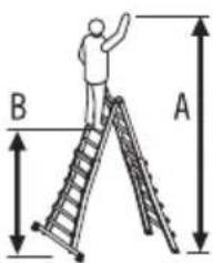
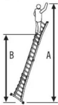
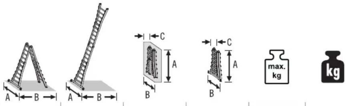
Number of ladder rungs
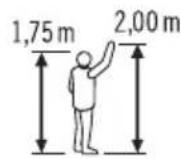
Reference person for body size and reaching height
A = highest possible reaching height
B = highest possible standing height
- Stepladder with sides extended to the maximum
- Single ladder with sides extended to the maximum
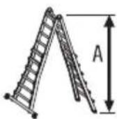
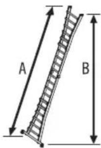
Dimensions of the
setup ladder
(sides extended to maximum)
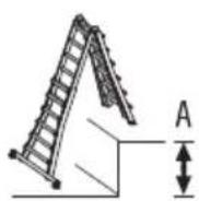
-Stepladder
A = Heigh
- Single ladder
A = Length of the ladder
B = Heigh
-Stepladder
(step adjustment)
A = maximum height compensation
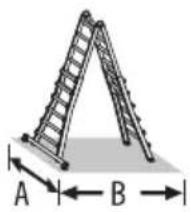
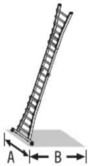

Dimensions of the
setup ladder
(sides extended to maximum)
-Stepladder
A = Width
B = Depth (support surface)
- Single ladder
A = Width
B = Depth (support surface)
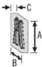
Dimensions of the
ladder collapsed
(Supplied state)
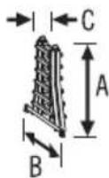
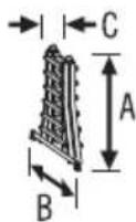
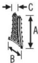
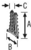
A = Length
B = Width
C = Depth
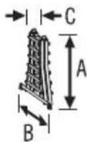
Dimensions of the
ladder collapsed
(Storage)
A = Length
B = Width
C = Depth
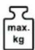
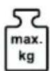
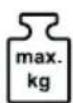
Highest possible
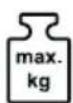
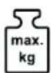
load capacity
Weight of the ladder
2. Intended use
This ladder is a moveable work tool that can be used in various locations.
With this ladder, small scale jobs can be carried out at heights at which use of other work tools is not commensurate.
This ladder may only be used as specified in these instructions for use. Any other use is considered as non-intended use and may lead to property damage or even to personal injury.
The ladder is not a toy.
The manufacturer or dealer shall not assume any liability for damage that has been caused by improper or incorrect use.
The user must always ensure that the ladder is suitable for the respective use; if necessary a risk assessment must be carried out in advance.
The legislation in the country of use must be complied with.
The standing step ladders comply with the requirements of the European standard EN 131-4. They are suitable for “professional use” and “non professional use”.


The highest possible load capacity of the ladder is 150 kg.
Modifications to the ladder that are not authorised by the manufacturer shall lead to termination of the guarantee and warranty.
3. Product overview
The single-hinge joint ladder M80 is a mobile, height-adjustable single ladder.
It offers a variable height adjustment by means of the extendable ladder rungs and can be very compactly collapsed for transport and storage.
The several ladder models differ from each other by the number of ladder rungs or an additional cross-bar for increased stability.
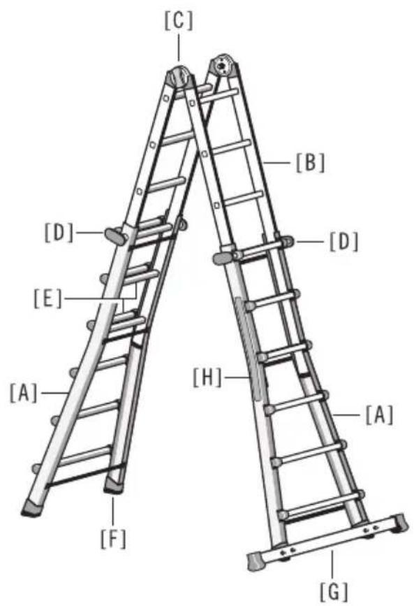
The technical information that is important for each type of ladder and information that is specific to each product are directly attached to the product on the ladder label [H].
[A] Extendable ladder leg
[B] Foldable ladder part
[C] Hinge joint
(safety joint with pre-set snap-in positions)
[D] Locking clamp
[E] ladder rung
[F] Ladder foot
[G] Crossbar with foot
[H] Ladder label
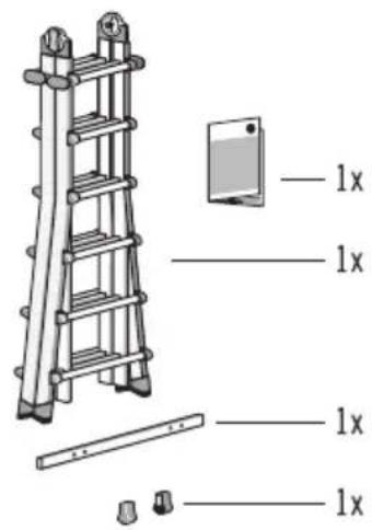
4. Scope of delivery
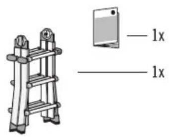
A) Single-hinge joint ladder 7512-XXX
1 x Instructions for use
1 x Single-hinge joint ladder
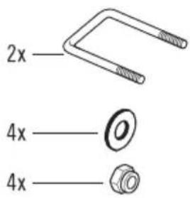
B) Single-hinge joint ladder 7516-XXX, 7520-XXX, 7524-XXX
1 x Instructions for use
1 x Single-hinge joint ladder
1 x Crossbar
1 x Set of feet for crossbar
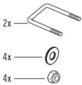
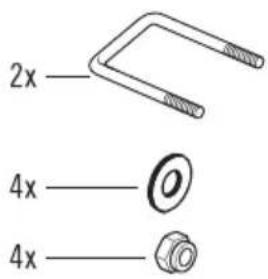
2 x U bolts M6
4 x M6 nut
4 x Washer
Check that the contents are complete and check for any possible transport damage before use.
Remove the packaging material.

WARNING
Risk of suffocation!
Packaging material is not a children's toy; there is a risk of suffocation if not handled properly.
- A)
B)
5. Safety instructions

WARNING
Danger of severe injuries!
In event of incorrect use or handling of the ladder, there are risks that may lead to severe injuries or even to death.
- There is inherently a risk of falling when using the ladder. All work with and on the ladder should therefore be carried out in such a way that a risk of falling is kept as low as possible.
- When using the ladder, there is also the risk of tipping over. Individuals can be injured and objects damaged due to the ladder tipping over. All work with and on the ladder should therefore be carried out in such a way that a risk of tipping over is kept as low as possible.
- The supplementary safety information symbols are meant to instruct the user of a ladder about what is necessary and what is not allowed for a safe use of a ladder in order to avoid accidents e.g. by falling from the ladder.
“Necessary” is indicated by a tick [ √ ] and “Not allowed” is indicated by an X [ ✗ ].

Inspect the ladder after delivery. Before every use visually check the ladder is not damaged and is safe to use. Do not use a damaged ladder.

Maximum total load.
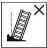
Do not use the ladder on a unlevel or unfirm base.
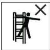
Do not overreach.

Do not erect the ladder on contaminated ground.

Maximum number of users.
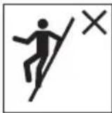
Do not ascend or descend unless you are facing the ladder.

Warning, fall from the ladder.

Refer to instruction manual/booklet.
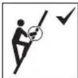
Keep a secure grip on the ladder when ascending and descending. Maintain a handhold whilst working from a ladder or take additional safety precautions if you cannot.
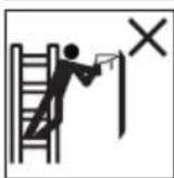
Avoid work that imposes a sideways load on ladders, such as side-on drilling through solid materials.
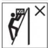
Do not carry equipment which is heavy or difficult to handle while using a ladder.
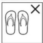
Do not wear unsuitable footwear when climbing a ladder.
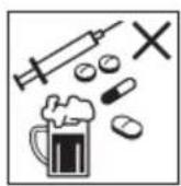
Do not use the ladder if you are not fit enough. Certain medical conditions or medication, alcohol or drug abuse could make ladder use unsafe.
Do not spend long periods on a ladder without regular breaks (tiredness is a risk).
Prevent damage of the ladder when transporting e.g. by fastening and ensure they are suitably placed to prevent damage.
Ensure the ladder is suitable for the task.
Do not use the ladder if contaminated, e.g. with wet paint, mud, oil or snow.
Do not use the ladder outside in adverse weather conditions, such as strong wind.
For professional use a risk assessment shall be carried out respecting the legislation in the country of use.
When positioning the ladder take into account risk of collision with the ladder e.g. from pedestrians, vehicles or doors.
Secure doors (not fire exits) and windows where possible in the work area.

Warning, electricity hazard.
Identify any electrical risks in the work area, such as overhead lines or other exposed electrical equipment and do not use the ladder where electrical risks occur.
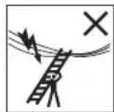
Use non-conductive ladders for unavoidable live electrical work.
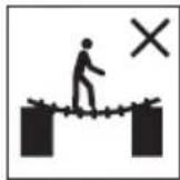
Do not use the ladder as a bridge.
Do not modify the ladder design.
Do not move a ladder while standing on it.
For outdoor use caution to the wind.
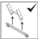
The crossbar must be installed before using the ladder.
(see 6. Instructions for assembly)


Ladder for "professional" and "non professional" use.
5. Safety instructions
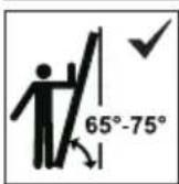
Leaning ladders with rungs shall be used at the correct angle.
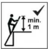
Ladders used for access to a higher level shall be extended at least 1 m above the landing point and secured, if necessary.
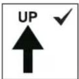
Only use the ladder in the direction indicated.
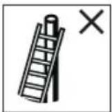
Do not lean the ladder against unsuitable surfaces.
Ladder shall never be moved from the top.
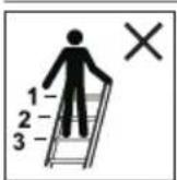
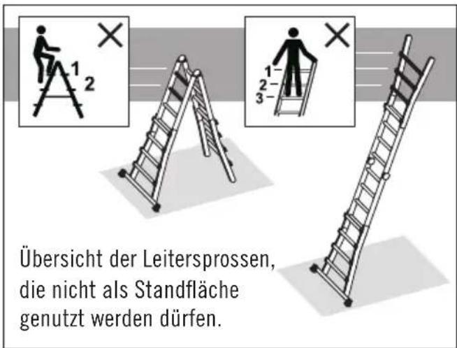
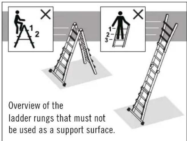
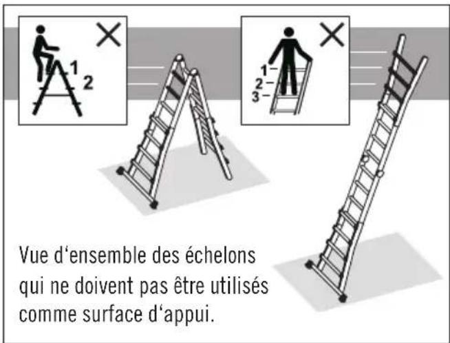
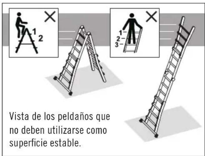
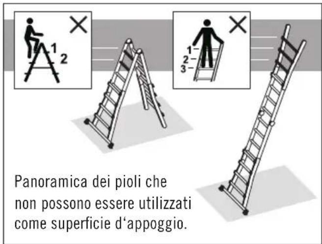
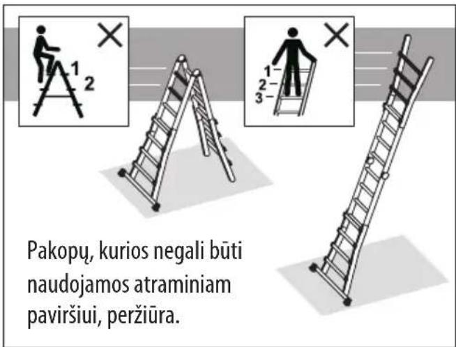
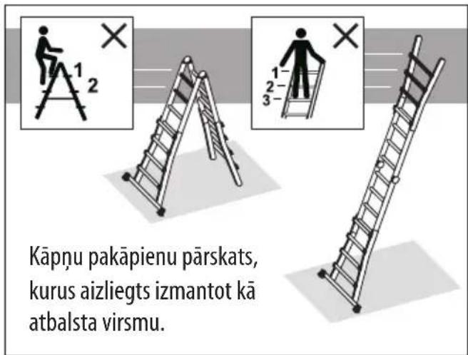
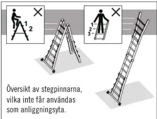
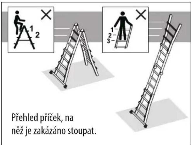
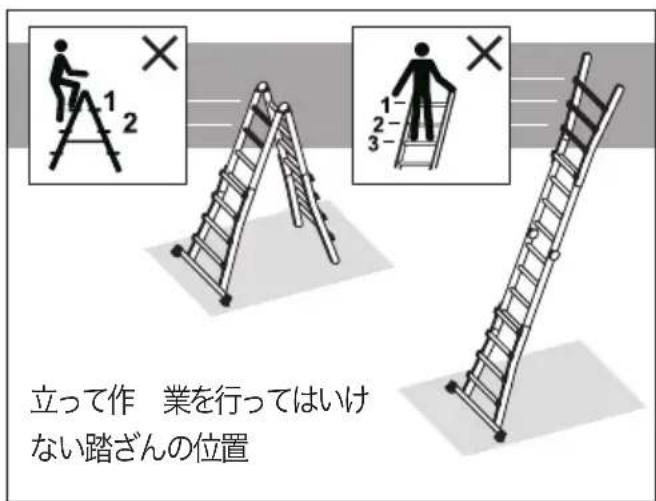
Do not stand on the top three steps/ rungs of a leaning ladder.
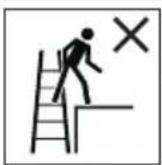
Do not step off the side of standing ladder onto another surface.

Open the ladder fully before use.
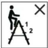
Do not stand on the top two steps/ rungs of a standing ladder without a platform and a hand/knee rail.
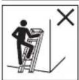
Standing ladders shall not be used as a leaning ladder.
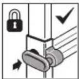
Before using, all locking clamps must be checked and completely engaged.
Single-jointed or multi-purpose ladders should be unfolded and folded together when they are lying on the floor and not in their position for use.

Make sure that the joints are locked.
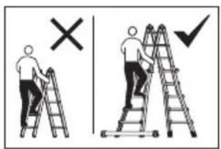
Single -hinge joint ladder (foldable ladder part) do not use without the extendable ladder sides.
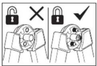
Only step on the ladder when it is locked. Locking pins can be seen on the inside of the safety joint.
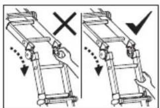
Danger of pinching! If handled without due care, fingers or hands can be pinched or trapped on parts of the housing.
6. Instructions for assembly
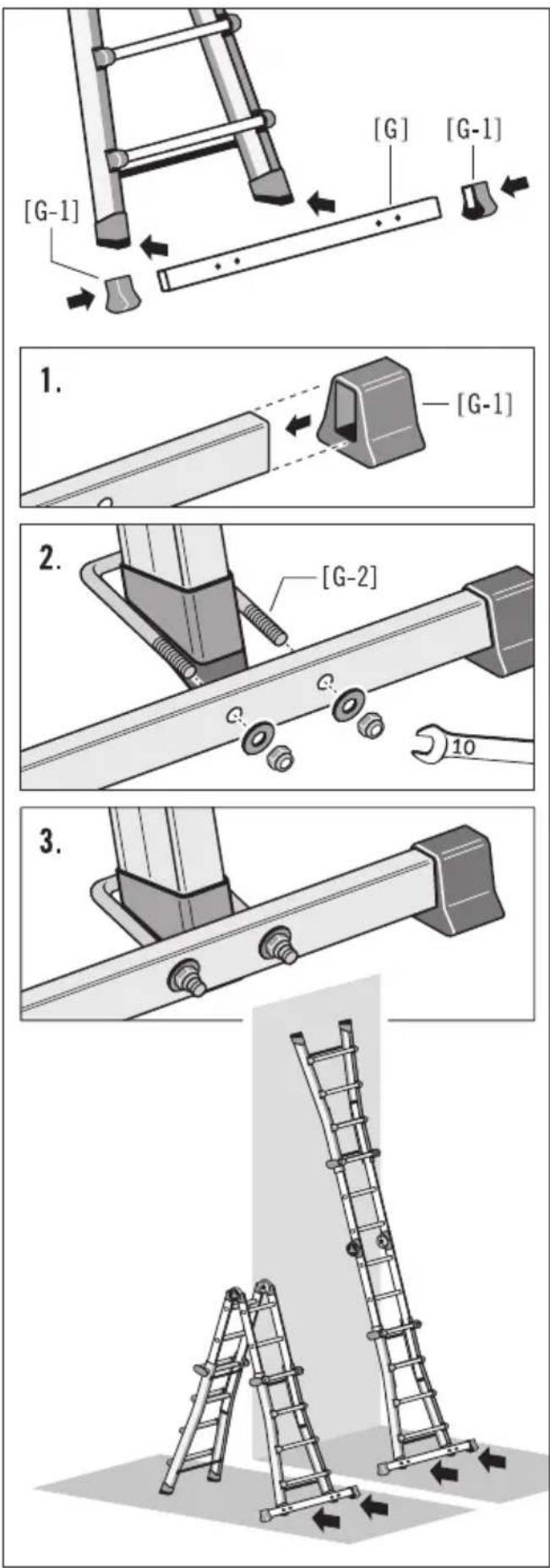
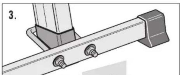
The single-hinge joint ladders art.-no. 7516-XXX, 7520-XXX and 7524-XXX are equipped with a crossbar that must be installed before using the ladder.
A spanner (spanner sizes 10) is required for assembly.
Attaching the feet:
- Push both feet [G-1] firmly onto the ends of the crossbar [G].
Install the crossbars:
The crossbar is attached to the feet of the extendable ladder sides.
- Position the U-bolt [G-2] and crossbar [G] at the base of the ladder side as shown.
- Then screw the crossbar tightly to both feet.

WARNING
Risk of serious injury as a result of the ladder tipping over!
Item no. 7516-xxx, 7520-xxx, 7524-xxx:
The ladders may only be used with the crossbar installed
7. Assembly and operation
After delivery and before each use examine the condition of the ladder, the function of all parts must be ensured.
NOTE
Caution, damage!
Always handle the ladder carefully.
Extend and collapse the ladder in a deliberate and careful way. If a rail is bent or damaged, the ladder can potentially be extended or collapsed only with difficulty or not at all.
7.1 Set-up options (schematic diagram)
The single-hinge joint ladder can be used as a single ladder and extension ladder and as a stepladder that can be climbed on both sides and as a stairway ladder.
The ladder is placed in the desired set-up position using two extendable ladder legs and a pair of snap-in hinge joints for locking and unlocking the ladder parts.
A - Stepladder with ladder legs extended
B - Stepladder with ladder legs inserted
C - Stepladder with step adjustment
D - Single ladder with legs inserted
E - Single ladder with legs extended
7.2 Adjusting for the step or single ladder
Using the hinge joint [C], the ladder is converted into either a stepladder or single ladder.
The foldable ladder part [B] is first unlocked and – after the ladder has been brought into the desired set-up position – locked again.
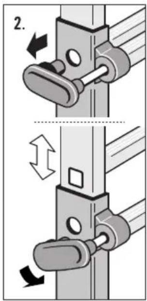
For adjusting one of the ladder parts, both of the safety joints on opposite sides of the ladder have to be activated.
Adjustment of the safety joint [C]:
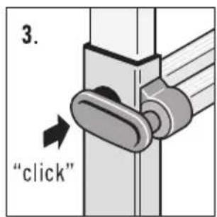
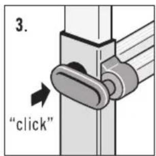
- Original position: the ladder is locked, and the clamp [C-3] is pushed in.
- Pull out the clamp [C-3] and place it on the safety joint by turning it slightly.
The locking opening is free, the ladder is unlocked and the ladder part [B] can now be adjusted into the desired position. - The ladder part [B] audibly clicks into place automatically. The ladder is locked, and the clamp [C-3] is pushed in.
7.3 Activating the extendable ladder legs
The ladder's height can be changed using the extendable sides [A].
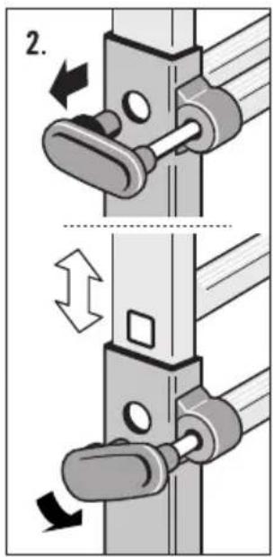
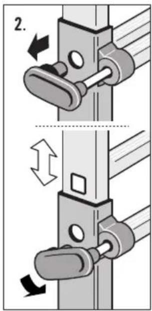
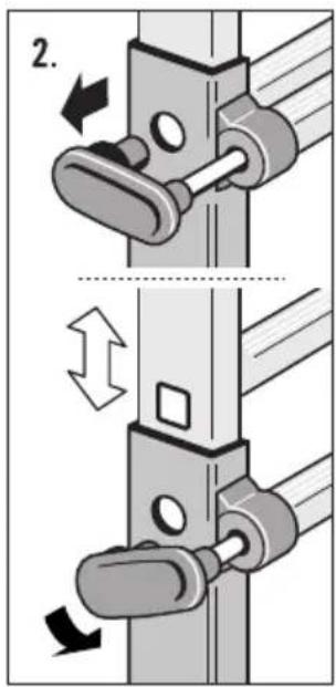
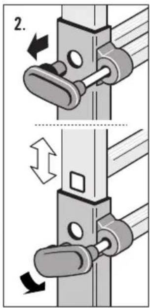
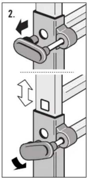
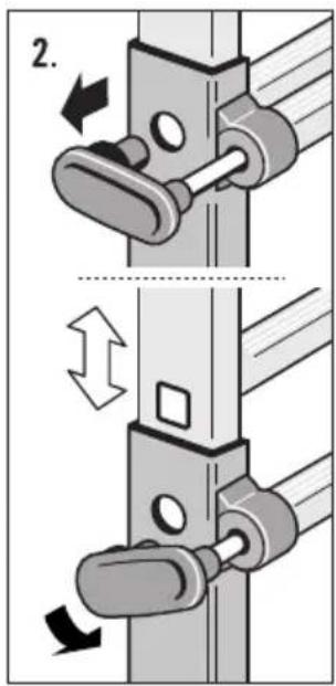
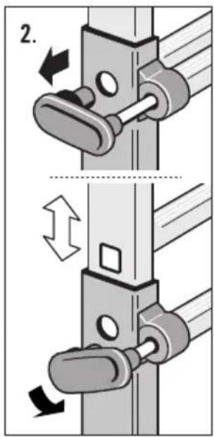
The extendable ladder sides are unlocked using the side locking clamps [D] and locked again after the ladder has been set up in position.
For adjusting one of the ladder parts, both locking clamps [D] have to be activated.
Adjusting the extendable ladder legs [A]:
- Original position: the locking clamp [D] is engaged.
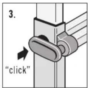
- Pull out the locking clamp [D] and place it on the ladder's side rail by turning it slightly. The locking opening is free, and the ladder is unlocked.
The extendable ladder leg [A] can now be moved into the desired position. - Then insert both locking clamps into the locking opening. The ladder is locked, and the locking clamp [D] is engaged.
This procedure is repeated once again to bring it into another set-up position.

en
7.2 7.3
![7524-XXX 7512-XXX 7516-XXX 7520-XXX 1. [C] [C-3] [C] [C-3]](/content/2026/04/717002/images/fc5dba61c6b65b188c32f4c7a23ef4fc49ac92c9575ce1c65b26d905729d3a57.jpg)
![2. [C-3] [B]](/content/2026/04/717002/images/08b6a71fd869e0ba25d0781d352403e1cf116cad3293c83e2eadae4f2b96ad62.jpg)
![3. "click" [C-3]](/content/2026/04/717002/images/6de48d6253a6ae8110691e01171b0a375186398b01dc450048458e8a0d261a65.jpg)
![[D] [A] [D] [A]](/content/2026/04/717002/images/9242cf8a2b543ff329b132039c084c8528262c95ff220061e2e61df656673b6b.jpg)
![1. [D] [A]](/content/2026/04/717002/images/c109a1c7620ab0f6718224f3bbdc79ac96f8eaa4894f4c08b930d5e469bb4f30.jpg)
7. Assembly and operation
7.4 Setting up and using the single-hinge joint ladder
A) Use as a stepladder:
The ladder must stand securely and firmly on the ground.
The hinge joints [C] and locking clamps [D] must be locked.
B) Use as a single ladder:
The ladder must stand securely on the ground and be leaning against a flat and secure surface.
The hinge joints [C] and locking clamps [D] must be locked.
Secure single ladders before using, e.g. tie down to ensure stability.
C) Storage:
The single-hinge joint ladder's individual elements can be folded together and pushed in for storage and transport.
The hinge joints [C] and locking clamps [D] must be locked.
![7.4 A) [C] [D] B) [D] [C] C) [C] [D]](/content/2026/04/717002/images/bdf56879ec58fc96fe008cddba568f651d4c76568d839d316e39a9e33071abca.jpg)
8. Transport and storage8. Transport and storage
NOTE
Caution, damage!
Incorrect handling of the ladder when transporting and storage may lead to damage to the ladder.
- The single-hinge joint ladder's individual elements can be folded together and pushed in for storage and transport.
The hinge joints [C] and locking clamps [D] must be locked.
- In order to avoid any damage, the ladder should be securely fastened (e.g., on roof carriers or in the car).
- Ladders should be stored in accordance with the producer's instructions.
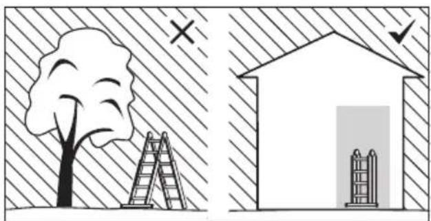
- Store the ladder away from areas where its condition could deteriorate more rapidly (e.g. dampness, excessive heat, or exposed to the elements).
- Ladders made of or using thermoplastic, thermo-setting plastic and reinforced plastic materials should be stored out of direct sunlight.
- Store the ladder in a position which helps it to remain straight (e.g. hung by the stiles on proper ladder brackets or laid on a flat clutter free surface).
- The ladder should be stored folded in a dry environment vertically or lying flat.
natural_image
Illustration showing a tree with ladder and a house with ladder, both under hatched background (no text or symbols)en
- Store the ladder where it cannot be damaged by vehicles, heavy objects, or contaminants?
- Store the ladder where it cannot cause a trip hazard or an obstruction?
- Store the ladder in such a way that it is protected from children at play and no person can be disabled by it
- Store the ladder securely where it cannot be easily used for criminal purposes.
- If the ladder is permanently positioned, make sure it is secured against unauthorized climbing (e.g. by children).
9. Care, maintenance and preventive maintenance
NOTE
Caution, damage!
Incorrect handling of the ladder during care and maintenance may lead to damage to the ladder.
- Care and maintenance of the ladder should insure its proper functioning. The ladder must be checked regularly for damages. The function of moving parts must be ensured.
- ALWAYS keep the ladder clean. Occasionally wipe the rails with a clean dry cloth. Paint and other ‘foreign matter’ can make extending and collapsing the ladder more difficult and should be removed immediately.
- Cleaning the ladder, especially of all moving parts, should occur immediately after use in the event of any visible soiling.
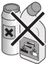
- Use only standard, water soluble cleaning agents. Do not use any aggressive scouring agents.
- Repairs and maintenance shall be carried out by a competent person and be in accordance with the producer's instructions.
NOTE: A competent person is someone who has the skills to carry out repairs or maintenance, e.g. by a training by the manufacturer.
- For repair and replacement of parts, e.g. feet, if necessary contact the producer or distributor.
10. Service life
When used for its intended purpose and regularly maintained, the ladder is a work tool that can be used for the long term.
11. Packaging and disposal

WARNING
Risk of suffocation!
Packaging material is not a children's toy; there is a risk of suffocation if not handled properly.
- If the ladder is scrapped, it must be disposed of in accordance with current legislations and regulations in the country of use.
- The product must not be disposed of in domestic waste.
- All components, including packaging must be sorted and separated accordingly.
- Aluminium is a high-grade material and should be put into the recycling system.
- Your municipality can give you detailed information about this.

12. Service and replacement parts
You can find these instructions for use on the internet at www.hailo.de.
You can obtain additional information about services and replacement parts directly from:
HAILO Werk • Daimlerstr. 8 • 35708 Haiger, Germany
Fon: +49 (0) 2773 82-0
Fax: +49 (0) 2773 82-1239
- There exists the risk of a fall due to damaged, defective or non-functional ladder units; there is also a risk of tipping over when using the ladder.
- Users of the ladder can sustain serious injuries during a fall.
-
Objects can likewise be damaged if the ladder tips over.
-
Regular inspection by a qualified person is required for commercial use.
- The contractor has to ensure that ladders are inspected recurrently for proper condition (visual and functional inspection).
For this purpose, the type, scope and time periods of the required inspections must be determined.
- The time intervals for the inspection will conform to the operating conditions, in particular the frequency of use and demands during use as well as the frequency and severity of established defects during the preceding inspections.
- The contractor also has to ensure that defective ladders are removed from use and stored in such a way that further use is not possible until proper maintenance or disposal takes place.
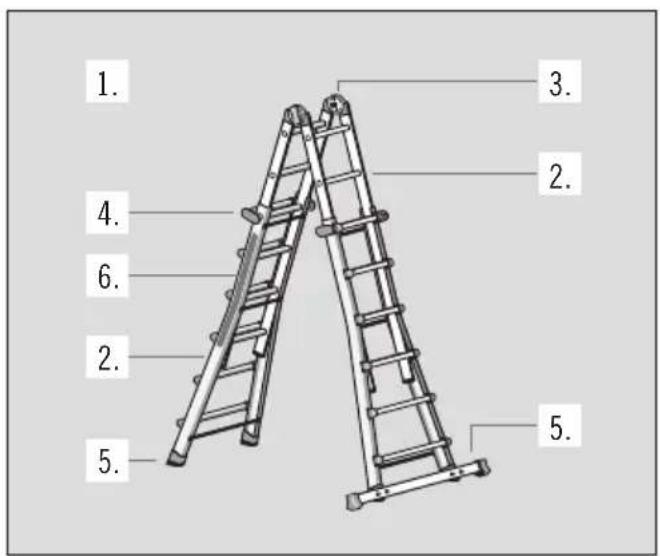
During the regular inspection of the ladder, inspection points 1-6 should be taken into account.
If any of the tested points cannot be fully satisfied, you should NOT use the ladder.
1. General inspection points
Are there any contaminants (e.g., dirt, mud, paint, oil or grease) on the ladder?
All fastenings (rivets, screws, bolts, etc.) must be completely present.
Are any fastenings possibly loose or corroded?
2. Ladder leg, foldable ladder part, ladder rung
Are the ladder side rails possibly bent, bowed, twisted, dented, cracked or corroded or rotten?
Check that the foldable ladder part/ladder legs around the fixing points for other components are in good condition.
All ladder rungs must be completely present.
Are ladder rungs possibly worn out, loose, corroded or damaged?
Inspect technical condition and functioning of the extendable ladder legs.
3.Hingejoints
Inspection of functionality, tightness and completeness as well as damage and corrosion. Is the hinge joint possibly damaged, loose or corroded?
4.Lockingclamp
Inspection of functionality, tightness and completeness as well as damage and corrosion. Are locking clamps possibly damaged, loose or corroded?
5.Crossbar,feet
Inspect crossbar and feet for tightness as well as damage and corrosion.
All ladder feet must be present.
Are any ladder feet loose, worn out or corroded?
6. Ladder labels
Are all labels present and perfectly legible?
natural_image
Diagram of a ladder leaning against a surface with labeled points A and B (no text or symbols beyond labels)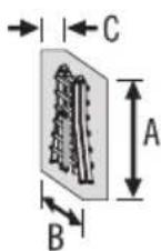

![3. "click" [C-3]](/content/2026/04/717002/images/162a437908c19eb129d5d50c540d8daa58fc2f35d74ea3327bc5e0a5fbc9c681.jpg)
![[D] [A] [D] [A]](/content/2026/04/717002/images/642233b1bf00f9eb3fa6637a92147bc8cf43977a116fe61fb66990b584747c97.jpg)
![1. [D] [A]](/content/2026/04/717002/images/d56ed4f50e49820f50083351d22ac09c0ca01768b334399d10023f546587ac01.jpg)
natural_image
Illustration showing a tree with ladder and a house with ladder, both under hatched shading (no text or symbols)natural_image
Diagram of a ladder leaning against a surface with labeled points A and B (no text or symbols beyond labels)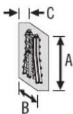

natural_image
Illustration showing a tree with ladder and a house with ladder, both under hatched background (no text or symbols)natural_image
Diagram of a ladder leaning against a surface with labeled points A and B (no text or symbols beyond labels)
![3. "click" [C-3]](/content/2026/04/717002/images/41ee5f5bdbfb449baf82e682b49a3f75c53c9436461af11274b52af2f5efe09c.jpg)
![[D] [A] [D] [A]](/content/2026/04/717002/images/62b8747e04cdde225466c39805e09db2f76398ae48f4003be84ceb52bb204842.jpg)
![1. [D] [A] 3. "click"](/content/2026/04/717002/images/a81c6d75ac66b4c7c2ee6b93b420681631ad553b84c9d2a731509c93b80b39c5.jpg)
7. Struttura e uso
natural_image
Illustration showing a tree with ladder and a house with ladder, both under hatched shading (no text or symbols)natural_image
Diagram of a ladder leaning against a surface with labeled points A and B (no text or symbols beyond labels)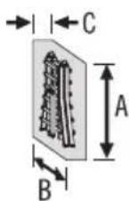
![3. "click" [C-3]](/content/2026/04/717002/images/cf79f74f35b99dff5c646e6f88b8ebe7554efebe63a1b0f173b01e9d82b8a6b3.jpg)
![[D] [A] [D] [A]](/content/2026/04/717002/images/c564bc17aec435b01748ead1ebae30e5000049601a70edfd719986b14a2ba687.jpg)
![1. [D] [A] 3. "click"](/content/2026/04/717002/images/8b20909cf19447a69a7f8f3b53579e899d4872f260e54e741acdfa83aa3d4628.jpg)
natural_image
Illustration showing a tree with ladder and a house with ladder, both under hatched background (no text or symbols)natural_image
Diagram of a ladder leaning against a surface with labeled points A and B (no text or symbols beyond labels)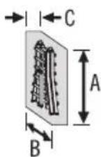
A = garums B = platums C = dzilums
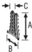
A = garums B = platums C = dzilums
![3. "click" [C-3]](/content/2026/04/717002/images/c01fa8952aedee572deb7238fe75920daef32dac404353661fc114fb0dcdb19b.jpg)
![[D] [A] [D] [A]](/content/2026/04/717002/images/cfc197a22dde3ce21dff41c56cdc0f7fa7b718344cde6bdcf7d9678e423d5d05.jpg)
![1. [D] [A]](/content/2026/04/717002/images/2c368b78caee0bb4618cf1c1e12fd2beefa69f0e345afd04d8aebcbaff7532f8.jpg)
natural_image
Illustration showing a tree with ladder and a house with ladder, separated by a diagonal hatched background (no text or symbols)natural_image
Diagram of a ladder leaning against a surface with labeled points A and B (no text or symbols beyond labels)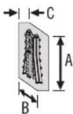
Art.nr. 7516-xxx, 7520-xxx, 7524-xxx:
![3. "click" [C-3]](/content/2026/04/717002/images/45d3a12526e7cd5d14df420a25cd9585afb53101904b009c1a43cd638080b4bb.jpg)
![[D] [A] [D] [A]](/content/2026/04/717002/images/df3db52f1a1a5912976567d8bfc672251c60d44c6385a851bcc3671195a5447c.jpg)
![1. [D] [A] 3. "click"](/content/2026/04/717002/images/903d7eb7959d502fc3eba32abb63e879cc250d10fd2100ca1366da243d2088cb.jpg)
natural_image
Illustration showing a tree with ladder and a house with ladder, both under hatched shading (no text or symbols)10. Livslängd
natural_image
Diagram of a ladder leaning against a surface with labeled points A and B (no text or symbols beyond labels)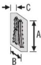

$$ C = h l o u b k a $$
$$ C = h l o u b k a $$
natural_image
Illustration showing a tree with ladder and a house with ladder, both under hatched shading (no text or symbols)7520-xxx (4 × 5 踏ざん)
7524-xxx (4 x 6 踏ざん)
目次
natural_image
Diagram of a ladder leaning against a surface with labeled points A and B (no text or symbols beyond labels)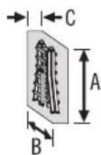

開いて立てた状 態での脚 立寸法
(脚柱が最大限に伸ばされた状態)
- 脚立
A = 幅
B = 奥行 (設置面)
- 梯子
A = 幅
B = 奥行 (設置面)
折り畳んだ状態での寸法 (納品状態)
A = さ
B = 幅
C = 行
折り畳んだ状態での寸法 (保管)
A = さ
B = 幅
C = 行
最大定格荷重
脚立重量
2. 使用用途
![2. [G-2] 10](/content/2026/04/717002/images/995a3cdf8878226009600203f3ac1b5b908cca0b48d8341d2b23acd230a0fbb2.jpg)
natural_image
Technical illustration of a metal bracket with bolts and a support structure (no text or symbols)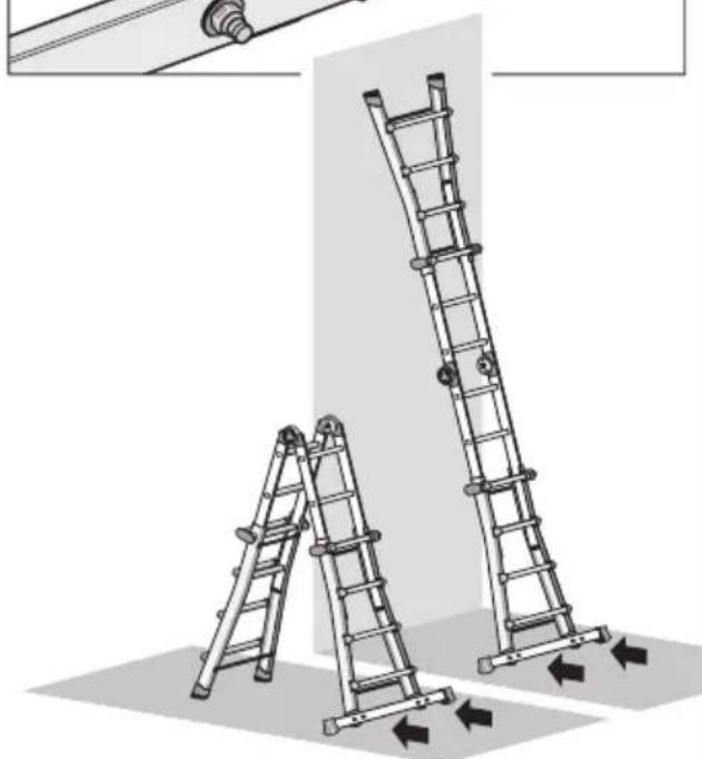
natural_image
Illustration of two metal ladders with directional arrows indicating movement or force (no text or symbols)7. セットアップ/操作
![3. "click" [C-3]](/content/2026/04/717002/images/d1418e5e11f14eb3f831ded04bea2462e10e7c8382f23c16a33632fdfaa78bc7.jpg)
![[D] [A] [D] [A]](/content/2026/04/717002/images/f74563338057eeca6cdcbe2af8c6eb5a18a957e1c64844861961c4271f367412.jpg)
![1. [D] [A] 3. "click"](/content/2026/04/717002/images/c047c799e3a5398797a3b6d1a4531c4a9d2a2622d0bab11943ef5ea524724f92.jpg)
7. セットアップ/操作
natural_image
Illustration showing a tree, ladder, and house with checkmarks (no text or symbols)| 7512-xxx | 4 x 3 | A = 8.89 ftB = 2.33 ft | A = 12.17 ftB = 5.61 ft | A = 4.43 ft | A = 9.02 ftB = 8.73 ft | A = 1.64 ft | |
| 7516-xxx | 4 x 4 | A = 10.50 ftB = 3.94 ft | A = 15.42 ftB = 8.86 ft | A = 6.07 ft | A = 12.40 ftB = 11.98 ft | A = 2.46 ft | |
| 7520-xxx | 4 x 5 | A = 12.14 ftB = 5.58 ft | A = 18.70 ftB = 12.14 ft | A = 7.71 ft | A = 15.91 ftB = 15.29 ft | A = 3.28 ft | |
| 7524-xxx | 4 x 6 | A = 13.81 ftB = 7.25 ft | A = 22.15 ftB = 15.58 ft | A = 9.35 ft | A = 19.23 ftB = 18.57 ft | A = 4.10 ft |
| A = 0,49 mB = 0,88 m | A = 0,49 mB = 0,78 m | A = 0,89 mB = 0,49 mC = 0,24 m | A = 0,89 mB = 0,49 mC = 0,24 m | max.150 kg | 9,05 kg | |
| A = 0,81 mB = 1,15 m | A = 0,81 mB = 1,04 m | A = 1,15 mB = 0,57 mC = 0,24 m | A = 1,15 mB = 0,81 mC = 0,27 m | max.150 kg | 12,65 kg | |
| A = 0,91 mB = 1,41 m | A = 0,91 mB = 1,32 m | A = 1,41 mB = 0,64 mC = 0,24 m | A = 1,41 mB = 0,91 mC = 0,27 m | max.150 kg | 15,16 kg | |
| A = 1,03 mB = 1,68 m | A = 1,03 mB = 1,57 m | A = 1,67 mB = 0,66 mC = 0,24 m | A = 1,67 mB = 1,03 mC = 0,27 m | max.150 kg | 19,50 kg |
| A = 1.61 ftB = 2.89 ft | A = 1.61 ftB = 2.56 ft | A = 2.92 ftB = 1.61 ftC = 0.79 ft | A = 2.92 ftB = 1.61 ftC = 0.79 ft | max.330 lbs | 19.95 lbs | |
| A = 2.66 ftB = 3.77 ft | A = 2.66 ftB = 3.41 ft | A = 3.77 ftB = 1.87 ftC = 0.79 ft | A = 3.77 ftB = 2.66 ftC = 0.89 ft | max.330 lbs | 27.89 lbs | |
| A = 2.99 ftB = 4.63 ft | A = 2.99 ftB = 4.33 ft | A = 4.63 ftB = 2.10 ftC = 0.79 ft | A = 4.63 ftB = 2.99 ftC = 0.89 ft | max.330 lbs | 33.42 lbs | |
| A = 3.38 ftB = 5.51 ft | A = 3.38 ftB = 5.15 ft | A = 5.48 ftB = 2.17 ftC = 0.79 ft | A = 5.48 ftB = 3.38 ftC = 0.89 ft | max.330 lbs | 42.99 lbs |
- Gebrauchsdauer
- Single-hinge joint ladder
- Table of Contents
- Introduction
- Explanation of symbols
- WARNING
- NOTE
- Intended use
- Product overview
- Scope of delivery
- Risk of suffocation!
- Safety instructions
- Danger of severe injuries!
- Instructions for assembly
- Attaching the feet:
- Install the crossbars:
- Assembly and operation
- Caution, damage!
- Set-up options (schematic diagram)
- Adjusting for the step or single ladder
- Activating the extendable ladder legs
- Setting up and using the single-hinge joint ladder
- A) Use as a stepladder:
- B) Use as a single ladder:
- C) Storage:
- Transport and storage8. Transport and storage
- Care, maintenance and preventive maintenance
- Service life
- Packaging and disposal
- Service and replacement parts
- General inspection points
- Ladder leg, foldable ladder part, ladder rung
- 3.Hingejoints
- 4.Lockingclamp
- 5.Crossbar,feet
- Ladder labels
- Struttura e uso
- Livslängd
- 目次
- 使用用途
- セットアップ/操作
Brand : HAILO
Model : M80
Category : Ladder