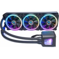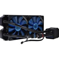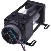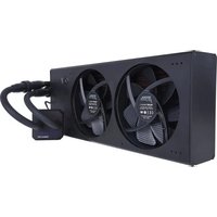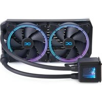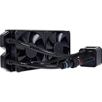
Eisbaer 240 - Computer cooling system Alphacool - Free user manual and instructions
Find the device manual for free Eisbaer 240 Alphacool in PDF.


User questions about Eisbaer 240 Alphacool
0 question about this device. Answer the ones you know or ask your own.
Ask a new question about this device
Download the instructions for your Computer cooling system in PDF format for free! Find your manual Eisbaer 240 - Alphacool and take your electronic device back in hand. On this page are published all the documents necessary for the use of your device. Eisbaer 240 by Alphacool.
USER MANUAL Eisbaer 240 Alphacool
natural_image
Technical line drawing of a mechanical fan assembly with coiled blades and mounting base (no text or symbols)EISBAER
V.4.004-01.2022
DEUTSCH....6
SAFETY INSTRUCTIONS....23
MOUNTING MATERIAL....24
TECHNICAL DETAILS 25
COOLER 25
PUMP 25
RADIATORS 26
QUICK COUPLING....26
MOUNTING THE RADIATOR....27
PUSHING FANS 27
SUCKING FANS 27
PREPARATION CPU....28
CPU COOLER ASSEMBLY 29
INTEL 1156 / 1155 / 1151 / 1150 / 1200 / 1700 .... 29
INTEL 2011 / 2011-3 / 2066....31
AMD AM3+ / AM3.... 33
AMD AM5 / AM4 35
CONNECTING FANS & PUMP....37
INITIAL START-UP....38
USING QUICK RELEASE CONNECTORS 38
FILLING UP COOLANT 39
FRANÇAIS 40
INSTRUCTIONS DE SECURITE....40
MATERIEL D'INSTALLATION....41
DETAILS TECHNIQUES 42
BLOC DE REFROIDISSEMENT 42
POMPE 42
RADIATEURS....43
RACCORDS RAPIDES 43
MONTAGE DE RADIATEUR....44
VENTILATEURS POUSSER.... 44
VENTILATEURS POMPER....44
PRÉPARATION CPU 45
INSTALLATION DE REFROIDISSEUR PROCESSEUR 46
INTEL 1156 / 1155 / 1151 / 1150 / 1200 / 1700 ....46
INTEL 2011 / 2011-3 / 2066....48
AMD AM3+ / AM3....50
AMD AM5 / AM4 52
BRANCHEMENT DES VENTILATEURS ET DE LA POMPE....54
MISE EN SERVICE 55
UTILISATION RACCORDS RAPIDES 55
REMLIR RESERVOIR 56
РУССКИЙ 57
text_image
67.30 66.00 66.00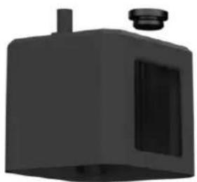
natural_image
3D rendered black mechanical component with a cylindrical top and rectangular cutout (no text or symbols)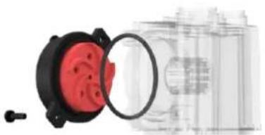
natural_image
Close-up of a red and black electrical socket with a magnified inset showing internal components (no text or symbols visible)PUMPE DC-LT 2
natural_image
Diagram of a mechanical assembly with multiple bolts and a circular component (no text or symbols)natural_image
3D rendering of a black square battery with orange top and side slots, showing a curved arrow indicating rotation (no text or symbols)natural_image
Three-step diagram showing a microchip with a yellow tape, a black pen inserted into a slot, and a blue tool inserted into a gray chip (no text or symbols)natural_image
3D CAD model of a mechanical flange component with mounting holes and internal channel (no text or symbols)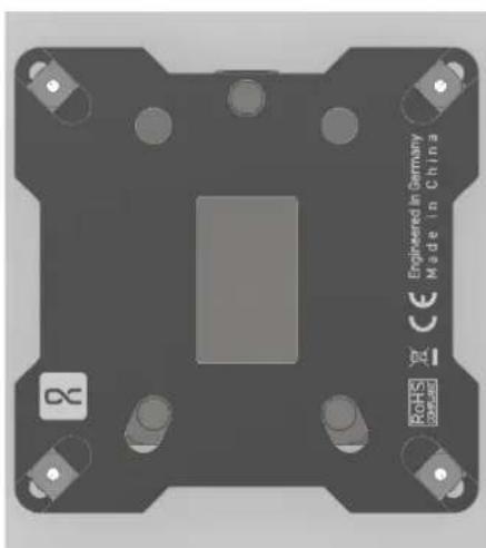
natural_image
Top-down view of a mechanical component with mounting holes and a central slot, labeled 'Engineered in Germany Made in China' (no other text or symbols visible)CPU - KÜHLERMONTAGE
INTEL 1156 / 1155 / 1151 / 1150 / 1200 / 1700
natural_image
3D diagram of a mechanical assembly with a central copper-colored component and two black brackets, connected by dashed lines (no text or symbols)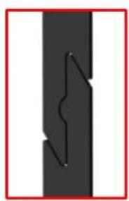
natural_image
Pure diagram of a vertical black bar with a zigzag line inside, no text or symbols presentnatural_image
3D rendering of a mechanical assembly with a central component and mounting base (no visible text or symbols)natural_image
3D mechanical assembly diagram showing a threaded bolt and bracket component with no visible text or symbolsnatural_image
3D rendering of a mechanical assembly with mounting base and cylindrical components (no visible text or symbols)
natural_image
3D rendering of a mechanical assembly with mounting base and clamping mechanism (no visible text or symbols)natural_image
3D mechanical assembly diagram showing a black housing with a brown base and blue dashed lines indicating alignment or connection points (no text or symbols)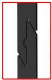
natural_image
Pure diagram of a vertical black bar with a zigzag line inside, no text or symbols presentnatural_image
3D rendering of a mechanical assembly with mounting base and internal components (no visible text or symbols)natural_image
Pure electrical connector wires without any text or symbolsnatural_image
Illustration of a chemical bottle pouring liquid into a conical flask on a base (no text or symbols visible)ENGLISH
SAFETY INSTRUCTIONS

READ THE SAFETY INSTRUCTIONS BEFORE STARTING THE INSTALLATION.

- Not suitable for children under 6 years. (contains small parts which could be swallowed).
- Do not run any cooling components without ensuring that cooling liquid is flowing through the cooling system. Coolers operated without coolant can become very hot. Caution: Burn Hazard!
- Coolers that have no coolant flowing through them can destroy the computer hardware. When switching on the hardware, always make sure that the pump is working.
- Please note when tightening the connectors or fittings, no tools such as screwdrivers, pliers, or wrenches should be used. All plastic products or metal threaded connections, which are linked with plastic parts, are easily over-loaded with tools. Cracking or other damages incurred in this way, as well as damage from leaking coolant, are not covered under the warranty!
- Use only connectors with a sealing o-ring. When using a sealing ring a firm tightening with the hand is enough. Your instruction manual will clearly refer to the use of tools in exceptional cases.
- If you have not done so yet, please check your hardware and cooling system (tightness, pump function and fans). This will minimize time spent searching for possible problems. ALPHACOOL INTERNATIONAL GMBH accepts no liability on the warranty of the manufacturer of the electronic components. The assembly of the cooling system takes place at your own risk.
- The screws should not be tightened too firmly. If you tighten the screws excessively, the knurled nuts can loosen and the cooler's uniform pressure is no longer guaranteed.
- Fasten the connections of your choice to the cooler. Do not use tools such as wrenches for fastening the connections. Connectors with 8mm long threads may stop the flow.
- We recommend a tightness test before assembling/installing the cooler. The water pressure in the water cooling loop can be at a maximum of 0.8 bar. DO NOT use tools on the connectors.
- Ensure that the cooler is touching all components to be cooled through thermal grease and thermal pads.
- Only use distilled water or ALPHACOOL CAPE KELVIN CATCHER in your cooling circuit. Damage caused by unsuitable coolant is not covered by the warranty!
Specified normal operation
All ALPHACOOL INTERNATIONAL GMBH cooling components are constructed and licensed for ALPHACOOL INTERNATIONAL GMBH computer construction parts. The warranty expires in case of misuse.
Warranty
- Data, designs, illustrations, technical data, weight, measurement and specifications, contained in folders, catalogues, circulars, announcements or price lists, have a purely informative character. We do not undertake warranty for the correctness of these data. As to the kind and the range of delivery, the data contained in the order and confirmation of order alone are decisive.
- If there is a lack of warrantor, you are entitled, on the basis of the legal regulations to require subsequent delivery, to withdraw from the contract or reduce the purchase price. If you are a consumer, the limitation period of warranty claims for the supplied commodity amounts to two years starting from receipt of goods ( § 13 BGB). If you are an entrepreneur, in accordance with legal conditions the limitation period amounts to only one year ( § 14 BGB).
- The warranty claim is valid only in combination with the original invoice, the sales slip or an ALPHACOOL confirmation on warranty claim.
- It is ALPHACOOL INTERNATIONAL GMBHs own discretionary authority to replace or repair the defective product or defective component. The replaced product or component changes into property of ALPHACOOL INTERNATIONAL GMBH.
- All warranty claims are accomplished by ALPHACOOL INTERNATIONAL GMBH or its authorized dealers. If the repair is carried out by a non-authorized or assigned person, ALPHACOOL INTERNATIONAL GMBH does not take over either costs or liability, unless the repair has been previously agreed upon with ALPHACOOL INTERNATIONAL GMBH.
- All costs resulting from refitting of the products are not taken over by ALPHACOOL INTERNATIONAL GMBH.
- ALPHACOOL INTERNATIONAL GMBHs warranty excludes the following points:
7.1. Regular controls maintenance and repair or the replacement of parts subject to regular wear and tear.
7.2. Improper manipulation or defects caused by incorrect installation.
7.3. Damages caused by storm, water, fire, overvoltage, acts of God, war, incorrect connection to the net, insufficient or incorrect ventilation or other reasons over which ALPHACOOL INTERNATIONAL GMBH has no influence.
7.4. Damages resulting from transportation or improper packaging.
- Consumer's rights are valid in the respective country; demands made to the salesman, as explained and laid down in the sales contract, will not be covered by this warranty. ALPHACOOL INTERNATIONAL GMBH, Its Branch Office and Distributors, are not responsible for direct or indirect damage or losses, as far as the
compelling legal regulations do not oppose it.
- ALPHACOOL INTERNATIONAL GMBH does not take over the warranty of the manufacturer of the electronic construction units and components. The assembly of the cooler takes place at your own risk.

Contact an authorized waste management company in your country. A waste removal with the municipal waste (unsorted garbage) or similar mechanisms for the collection of local wastes is not permissible!
MOUNTING MATERIAL
| RADIATOR & FANS |  number varies depending on the product version number varies depending on the product version |  memberiesndingtheductversion memberiesndingtheductversion | 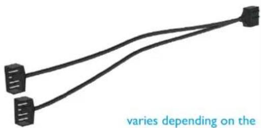 product version you purchased product version you purchased | |
| M3x5 | M3x30 | Y-adaptor 4-Pin PWM | ||
| EISBAER CPU COOLER | 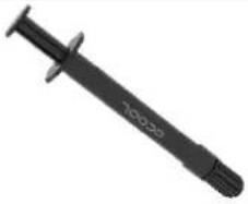 | 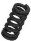 | 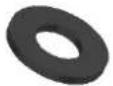 | |
| lx thermal grease | 4x springs | 4x 0.5 mm washers | ||
| AMD | 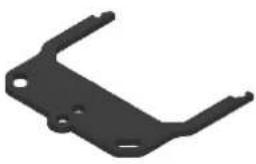 | 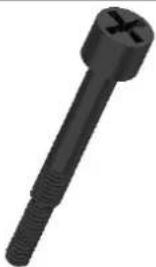 | 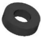 | |
| lx bracket set | 4x AMD screws | 4x 2.0 mm washers | ||
| INTEL | 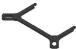 |  | 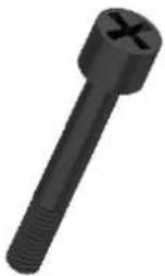 | 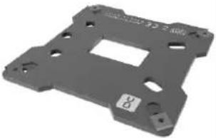 |
| lx bracket set | 4x 1150 screws | 4x 2011 screws | lx backplate | |
TECHNICAL DETAILS
COOLER Eisbaer
AMD: AM5 / AM4 / AM3+ / AM3
INTEL: 2011 / 2011-3 / 2066 / 1156 / 1155 / 1151 /
1150 / 1200 / 1700
Mounting kits for TR4 (Art. No.: 12875) & 2011-3 Narrow ILM (Art. No.: 12531) are available separately.
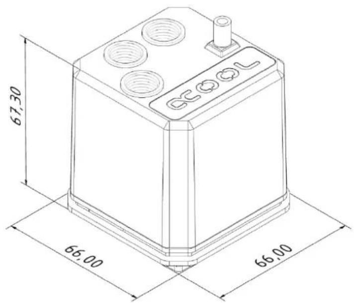
text_image
67,30 66.00 66.00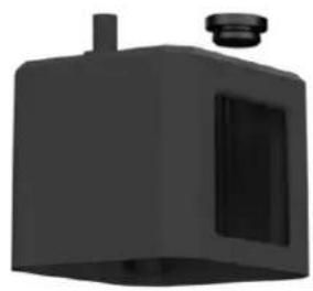
natural_image
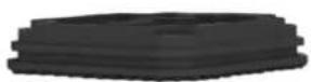
3D rendered image of a black industrial component with a cylindrical top and rectangular opening (no text or symbols)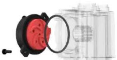
natural_image
Close-up of a red plastic electrical plug with a magnified inset showing internal components (no text or symbols visible)PUMP DC-LT 2
Power consumption: 4 W
Voltage: 12 V DC
Maximum flow rate: 75 l/h
Maximum head: 0,95 m
Power connector: 3-Pin
natural_image
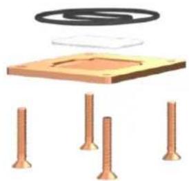
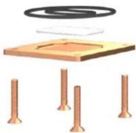
Diagram of a mechanical assembly with four bolts and a coil above a base plate (no text or symbols)RADIATORS NexXxos Series
Material: Copper
Model variants: XT45 120
dimension: 160 mm x 124 mm x 45 mm
ST30 140
dimension: 178 mm × 144 mm × 30 mm
ST30 240
dimension: 278 mm × 124 mm × 30 mm
ST30 280
dimension: 316 mm x 144 mm x 30 mm
ST30 360
dimension: 397 mm x 124 mm x 30 mm
ST30 420
dimension: 459 mm × 144 mm × 30 mm
QUICK COUPLING Compatibility: 11/8 mm tubes
Material: Nylon
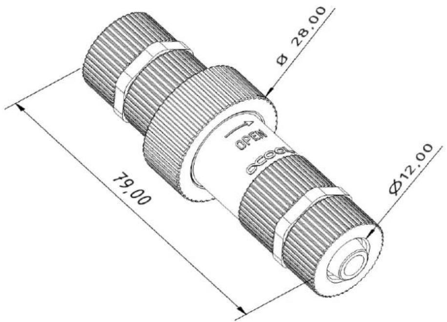
text_image
79.00 φ 28.00 OPEN φ12.00MOUNTING THE RADIATOR
PUSHING FANS
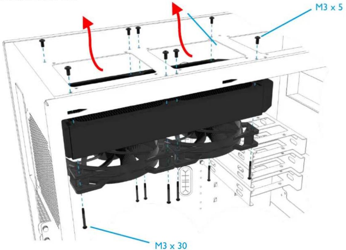
text_image
M3 x 5 M3 x 30SUCKING FANS
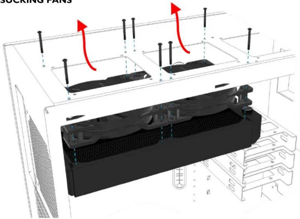
text_image
SCCKING PANSPREPARATION CPU
- Remove the protective film from the cooling plate.
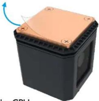
natural_image
3D rendering of a black rectangular electronic component with a copper-colored top and orange base, showing a blue arrow indicating rotation (no text or symbols)- Remove any remaining thermal paste from the CPU.
- Apply a pea-sized blob of thermal paste to the center of the CPU.
- Spread the paste using a spatula, or similar to an even, thin layer (< 0.5 mm layer thickness).
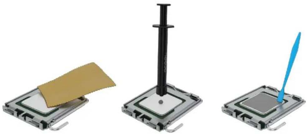
natural_image
Three-step diagram showing a microchip with a gold sheet, a black pen inserted into a square base, and a blue tool inserted into a gray chip (no text or symbols)- Remove the protective film from the adhesive strips of the included backplate. Please note the correct alignment of the backplate:
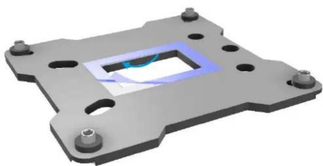
natural_image
3D CAD model of a mechanical flange component with mounting holes and a central internal cavity (no text or symbols)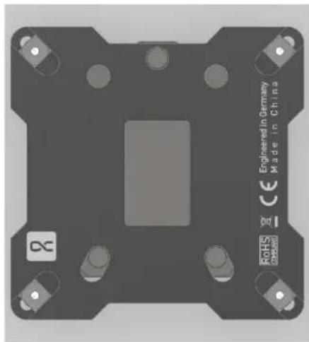
natural_image
Top-down view of a mechanical component with mounting holes and a central square cutout (no text or symbols visible)CPU COOLER ASSEMBLY
INTEL 1156 / 1155 / 1151 / 1150 / 1200 / 1700
- Select the appropriate bracket and screws.
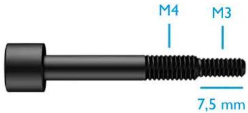
text_image
M4 M3 7,5 mm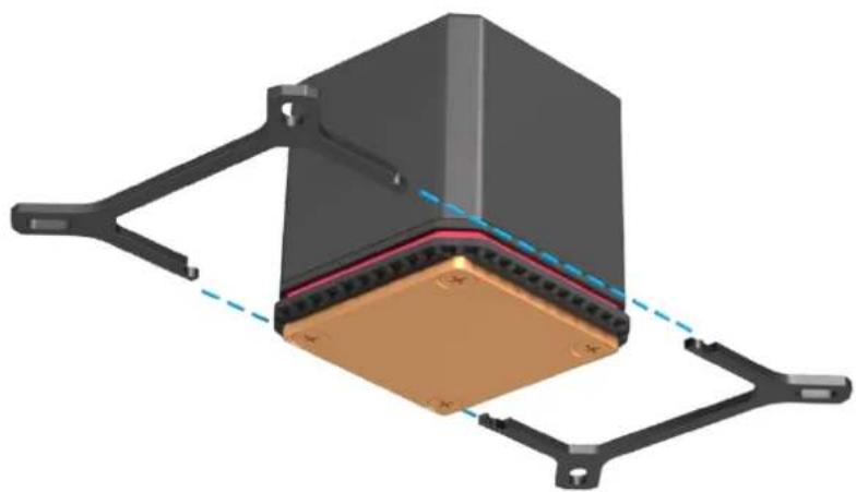
natural_image
3D mechanical assembly diagram showing a rectangular component with mounting brackets and a central copper-colored base, connected by dashed lines (no text or symbols)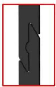
natural_image
Pure diagram of a vertical black bar with a zigzag line inside, no text or symbols present- Plug the bracket together as shown.
- Slide the compression springs and washers onto the screws and fix them to the bracket.
- Remove any remaining thermal paste from the CPU.
1156 / 1155 / 1151 / 1150 / 1200
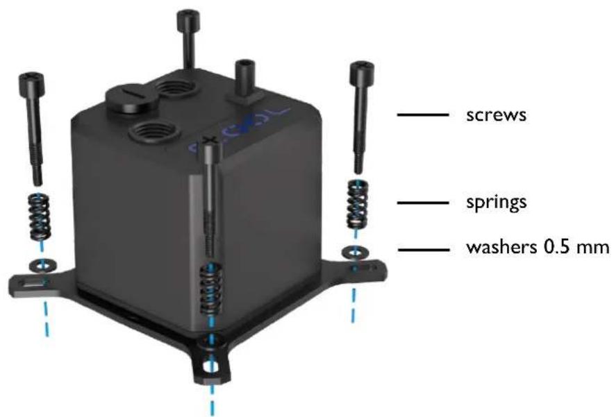
text_image
screws springs washers 0.5 mm1700
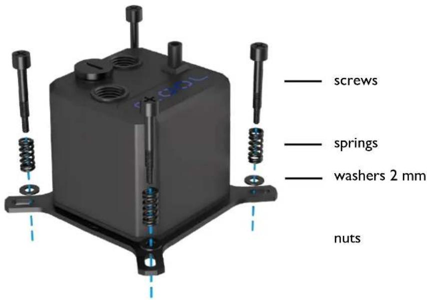
text_image
screws springs washers 2 mm nuts- Attach the cooler to the socket using the backplate. Tighten the screws crosswise, hand-tight.
- Make sure that the window is facing upwards (or that the Alphacool logo can be read from the front). This design ensures that the pump does not run dry.
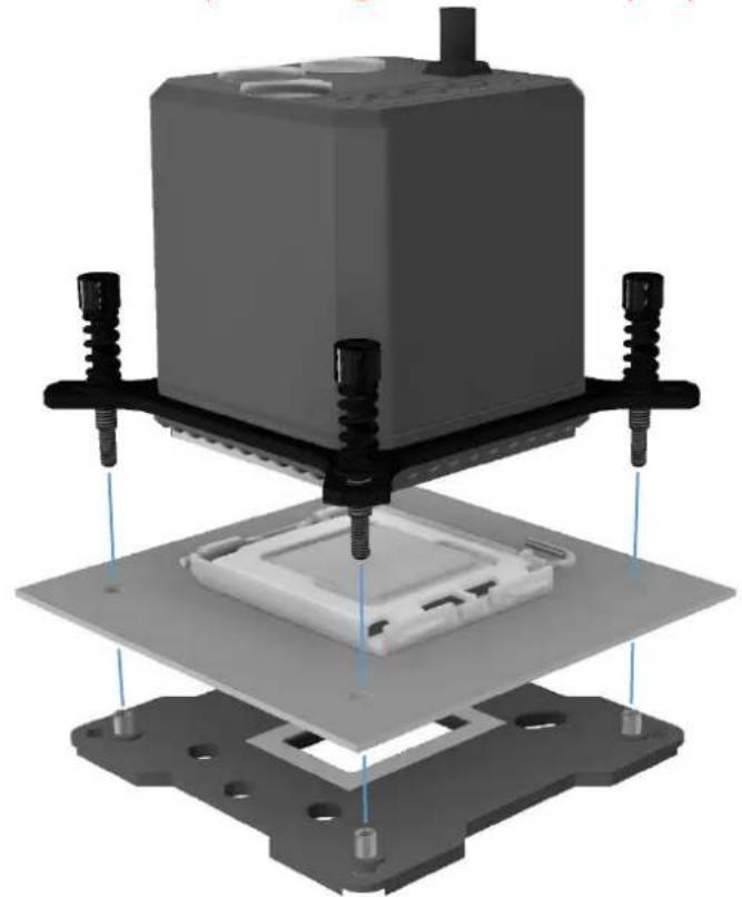
natural_image
3D rendering of a mechanical assembly with a central component and mounting base (no text or symbols visible)
Do not use tools.
Tighten only by hand!!
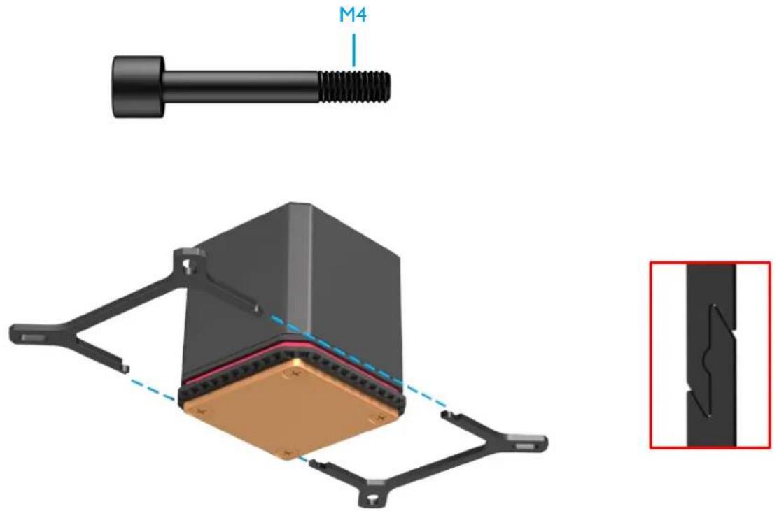
INTEL 2011 / 2011-3 / 2066
- Select the appropriate bracket and screws.
text_image
M4- Plug the bracket together as shown.
- Slide the compression springs and washers onto the screws and fix them to the bracket.
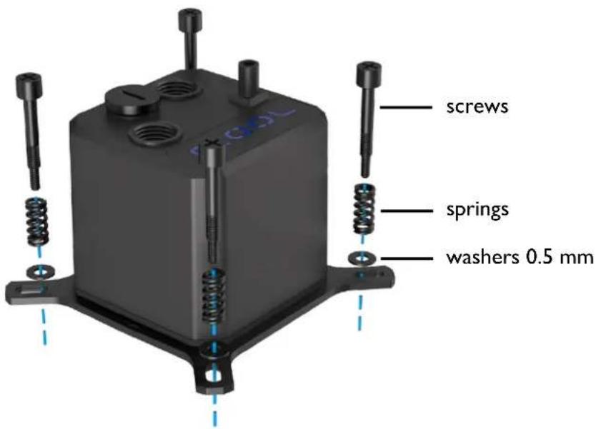
text_image
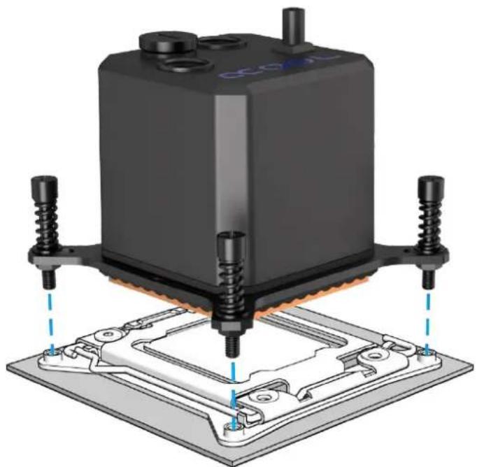
screws springs washers 0.5 mm- Attach the cooler to the socket as shown. Tighten the screws crosswise, hand-tight.
- Make sure that the window is facing upwards (or that the Alphacool logo can be read from the front). This design ensures that the pump does not run dry.
natural_image
3D rendering of a mechanical assembly with mounting base and screw fasteners (no visible text or symbols)
Do not use tools.
Tighten only by hand!!
Note: Some 2011/- 3 Socket motherboards have continuous threaded mounting holes in the base. In this case, do not tighten the screws more than 4 mm.
AMD AM3+ / AM3
- Select the appropriate bracket and screws.
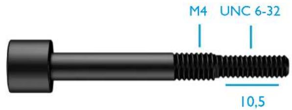
text_image
M4 UNC 6-32 10,5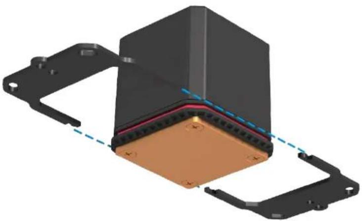
natural_image
3D mechanical assembly diagram showing a component with mounting flanges and a central copper-colored base (no text or symbols)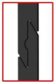
natural_image
Pure diagram of a vertical black bar with a zigzag line inside, no text or symbols present- Plug the bracket together as shown.
- Slide the compression springs and washers onto the screws and fix them to the bracket.
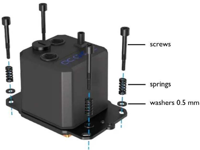
text_image
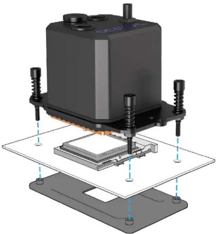
screws springs washers 0.5 mm- For the mounting on the socket you need the original backplate of the mainboard.
- Attach the cooler to the socket as shown. Tighten the screws crosswise hand-tight.
- Make sure that the window is facing upwards (or that the Alphacool logo can be read from the front). This design ensures that the pump does not run dry.
natural_image
3D diagram of a mechanical assembly with mounting base and internal components (no text or symbols)
Do not use tools.
Tighten only by hand!!
AMD AM4 / AM5
- Select the appropriate bracket and screws.
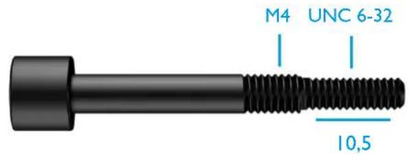
text_image
M4 UNC 6-32 10,5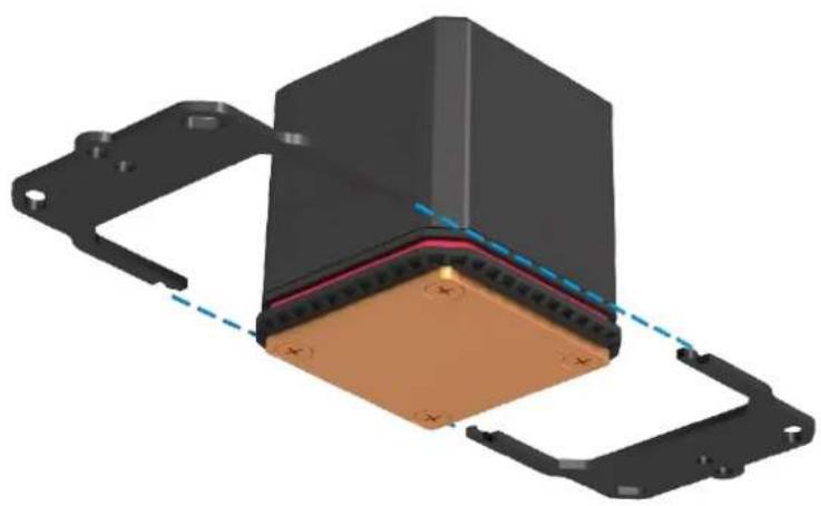
natural_image
3D mechanical assembly diagram showing a component with mounting flanges and a central copper-colored base (no text or symbols)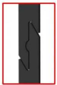
natural_image
Pure diagram of a vertical line with a zigzag arrow, no text or symbols present- Plug the bracket together as shown.
- Slide the compression springs and two different washers onto the screws and fix them to the bracket.
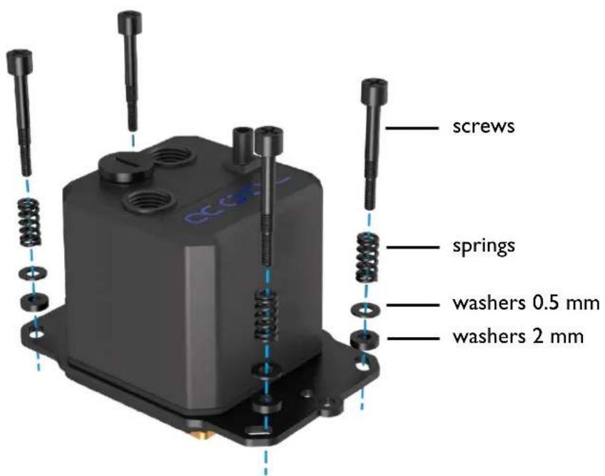
text_image
screws springs washers 0.5 mm washers 2 mm- For the mounting on the socket you need the original backplate of the mainboard.
- Attach the cooler to the socket as shown. Tighten the screws crosswise hand-tight.
- Make sure that the window is facing upwards (or that the Alphacool logo can be read from the front). This design ensures that the pump does not run dry.
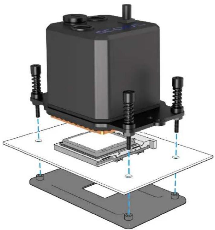
natural_image
3D rendering of a mechanical testing setup with a black block and layered components (no visible text or symbols)
Do not use tools.
Tighten only by hand!!
- Connect the fan cables with the included PWM adapter.
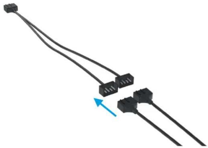
natural_image
Pure electrical connector wires without any text or symbols- Connect the PWM adapter and the 3-pin connector of the pump to your mainboard.
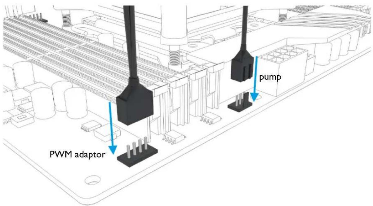
text_image
PWM adaptor pumpINITIAL START-UP
If your Eisbaer AiO is unusually loud during initial operation, tipping the entire PC case back and forth a little can help. The higher volume level of the pump occurs due to air bubbles in the closed system. These bubbles form during transport or due to movement during installation.
Double-check that the radiator is mounted above the water block. This setup helps de- aerate the system. After around 12 hours of operation any air in the system should be eliminated and the pump should run quietly as usual.
USING QUICK RELEASE CONNECTORS
The pre-installed quick-release fastener offers the possibility of expanding the Eisbaer loop quickly and easily. The connector is compatible with many other products from our range. Attention: 2 - 3 drops of water can escape when unscrewing the quick release mechanism – This is normal.
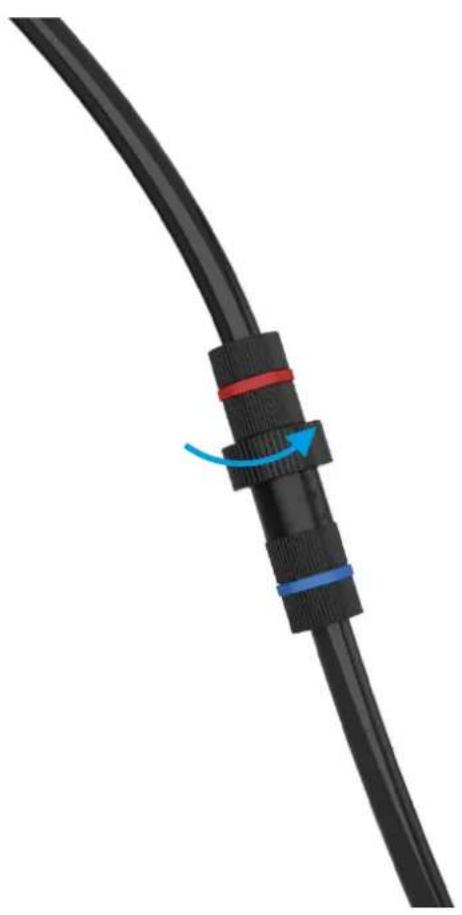
natural_image
Close-up of a black cable with red and blue connectors, showing a blue arrow indicating rotation (no text or symbols)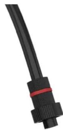
natural_image
Close-up of a black cable with red connectors (no text or symbols visible)WATER OUTLET
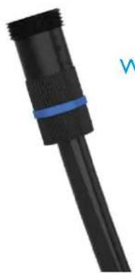
natural_image
Close-up of a black plastic cable with a blue strap, no visible text or symbolsWATER INLET
FILLING UP COOLANT
The Eisbaer All-in-One is prefilled and normally it is not necessary to top up the coolant. If you want to expand your circuit, e.g. with a GPX Eiswolf graphics card cooler, it is advisable to check the water level. If the pump is running unusually loud, liquid should be topped up urgently. We only recommend clear coolants from our own production (CKC or Eiswasser Crystal - no UV!) or pure distilled or osmosis filtered water.
A fillport on the cooler is provided for filling. We recommend using a funnel or a filling bottle:
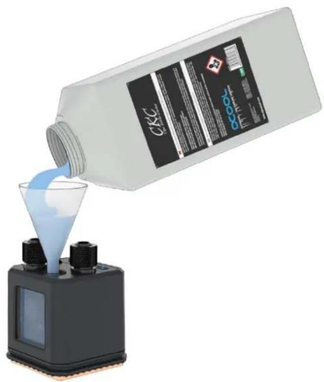
natural_image
Illustration of a CKC fuel being poured into a conical flask using a digital device (no text or symbols visible)FRANÇAIS
INSTRUCTIONS DE SECURITE

LISEZ LES INSTRUCTIONS DE SECURITE AVANT DE COMMENCER L'INSTALLATION.

text_image
67.30 66.00 66.00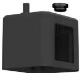
natural_image
3D rendering of a black industrial container with a side panel and top port (no text or symbols visible)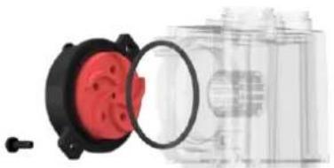
natural_image
Diagram of a mechanical component with red and black parts, showing a magnified view of a cylindrical part (no text or symbols present)POMPE DC-LT 2
Consommation : 4 W
Tension : 12 V DC
natural_image
Diagram of a mechanical assembly with four cylindrical pins and a top plate (no text or symbols)dimensions: 160 mm × 124 mm × 45 mm
ST30 140
dimensions: 178 mm × 144 mm × 30 mm
ST30 240
dimensions: 278 mm × 124 mm × 30 mm
ST30 280
dimensions: 316 mm × 144 mm × 30 mm
ST30 360
dimensions: 397 mm x 124 mm x 30 mm
ST30 420
dimensions: 459 mm × 144 mm × 30 mm
natural_image
3D rendering of a black rectangular battery with a square top and orange insulation, showing a curved arrow indicating rotation (no text or symbols)natural_image
Three-step diagram showing a microchip with a yellow tape, a black pen inserted into a square base, and a blue tool inserted into a chip (no text or symbols)natural_image
3D CAD model of a mechanical flange component with mounting holes and a central internal cavity (no text or symbols)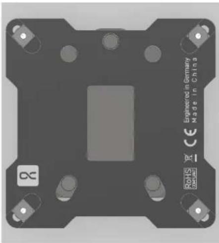
natural_image
Top-down view of a black industrial chip component with mounting holes and a central slot, labeled 'Engineered in Germany Made in China' (no other text or symbols visible)INSTALLATION DE REFROIDISSEUR PROCESSEUR
INTEL 1156 / 1155 / 1151 / 1150 / 1200 / 1700
natural_image
3D diagram of a mechanical assembly with a central copper-colored component and two black brackets, connected by dashed lines (no text or symbols)
natural_image
Pure diagram of a vertical line with a zigzag path, no text or symbols presentnatural_image
3D rendering of a mechanical assembly with a central component and mounting base (no text or symbols visible)natural_image
3D rendering of a mechanical assembly with threaded components and mounting base (no visible text or symbols)natural_image
3D mechanical assembly diagram showing a component with mounting flanges and a central base (no text or symbols)
natural_image
Pure diagram of a vertical black bar with a zigzag line inside, no text or symbols presentnatural_image
3D rendering of a mechanical assembly with mounting base and internal components (no visible text or symbols)natural_image
3D mechanical assembly diagram showing a component with mounting flanges and a central copper-colored base (no text or symbols)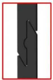
natural_image
Pure diagram of a vertical line with a zigzag arrow, no text or symbols presentnatural_image
3D rendering of a mechanical assembly with mounting base and internal components (no visible text or symbols)natural_image
Pure electrical connector diagram showing three black terminal blocks connected by wires, with a blue arrow indicating direction (no text or symbols)natural_image
Illustration of a bottle pouring liquid into a conical flask on a digital device (no text or symbols visible)text_image
67.30 66.00 66.00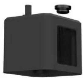
natural_image
3D rendering of a black industrial device with a cylindrical top and side panel (no text or symbols visible)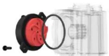
natural_image
Close-up of a red and black plastic component with a magnifying glass, next to a transparent cylindrical object (no visible text or symbols)ПОМПА DC-LT 2
natural_image
Diagram of a microelectromechanical assembly with four pins and a coil above (no text or symbols)natural_image
3D rendering of a black square battery with a copper-colored top and orange casing, showing a blue rotation arrow (no text or symbols)natural_image
Three-step diagram showing a microchip with a gold sheet, a black pen inserted into a square base, and a blue tool inserted into a small chip (no text or symbols)natural_image
3D CAD model of a mechanical bracket with mounting holes and a central internal cavity (no text or symbols)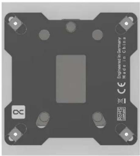
natural_image
3D rendering of a mechanical component with mounting holes and a central square cutout, labeled 'Engineered in Germany Made in China' (no other text or symbols visible)natural_image
3D rendering of a mechanical assembly with mounting brackets and a central component (no text or symbols visible)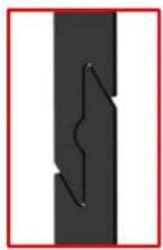
natural_image
Pure diagram of a vertical black bar with a zigzag line inside, no text or symbols presentnatural_image
3D rendering of a mechanical assembly with a black box and layered components (no text or symbols visible)natural_image
3D diagram of a mechanical assembly with a copper-colored base and black brackets, no visible text or symbols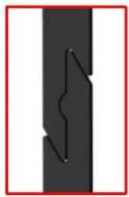
natural_image
Pure diagram of a lightning bolt inside a vertical black rectangle with white borders (no text or symbols)natural_image
3D mechanical component with multiple springs and mounting holes, no visible text or symbolsВинты
Нажимные пружины
natural_image
3D rendering of a mechanical assembly with mounting base and cylindrical components (no visible text or symbols)natural_image
3D mechanical assembly diagram showing a component with mounting flanges and a central copper-colored base (no text or symbols)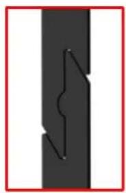
natural_image
Pure diagram of a vertical black bar with a zigzag line inside, no text or symbols presentnatural_image
3D rendering of a mechanical testing setup with a black block and base platform (no visible text or symbols)natural_image
3D mechanical assembly diagram showing a black housing with a copper-colored base and mounting brackets (no text or symbols)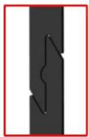
natural_image
Pure diagram of a vertical black bar with a zigzag line inside, no text or symbols presentnatural_image
3D rendering of a mechanical assembly with mounting base and internal components (no visible text or symbols)natural_image
Pure electrical connector diagram showing three black cable terminals connected by a blue arrow (no text or symbols)natural_image
Illustration of a chemical bottle pouring liquid into a conical flask (no text or symbols visible)日本語
安全上の注意

text_image
67.30 66.00 66.00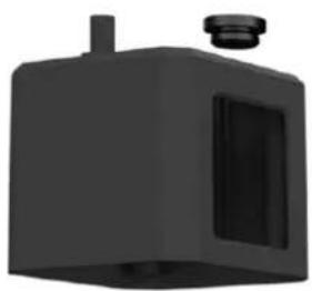
natural_image
3D rendered image of a black industrial component with a cylindrical top and side panel (no text or symbols)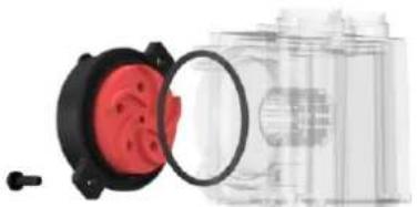
natural_image
Exploded view of a mechanical component with red and black parts, no visible text or symbolsポンプ DC-LT 2
消費電力:4 W
電圧: 12 V DC
最大流量:75 l/h
最大ヘッド:0,95 m
電源プラグ 3 ピン
natural_image
Diagram of a mechanical assembly with four cylindrical pins and a top plate, no text or symbols present.ラジェータ NexXxos シリーズ
材質:銅
モデルバリアント XT45 120
寸法: 160 mm × 124 mm × 45 mm
ST30 140
寸法:178 mm × 144 mm × 30 mm
ST30 240
寸法: 278 ~mm × 124 ~mm × 30 ~mm
ST30 280
寸法: 316 ~mm × 144 ~mm × 30 ~mm
ST30 360
寸法: 397 ~mm × 124 ~mm × 30 ~mm
ST30 420
寸法: 459 ~mm × 144 ~mm × 30 ~mm
natural_image
3D rendering of a black rectangular battery with a square top and orange casing, showing a blue arrow indicating rotation (no text or symbols)natural_image
Three 3D renderings of a microchip with a gold sheet, a black pen inserted vertically, and a blue tool inserted into a gray substrate (no text or symbols visible)natural_image
3D CAD model of a mechanical flange component with mounting holes and a central internal cavity (no text or symbols)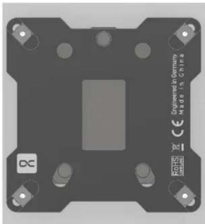
natural_image
3D rendering of a mechanical component with mounting holes and a central slot, labeled 'Engineered in Germany Made in China' (no other text or symbols visible)CPU クーラー取り付け
INTEL 1156 / 1155 / 1151 / 1150 / 1200 / 1700
text_image
M4 M3 7.5 mm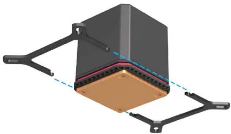
natural_image
3D mechanical assembly diagram showing a layered component with mounting brackets and a central copper-colored base (no text or symbols)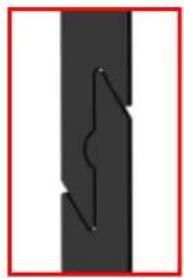
natural_image
Pure diagram of a vertical black bar with a zigzag line inside, no text or symbols presentnatural_image
3D rendering of a mechanical assembly with a black block and a gray base plate (no text or symbols visible)
工具を使わないでください。
手のみで締めてください!
INTEL 2011 / 2011-3 / 2066
natural_image
3D rendering of a mechanical assembly with mounting base and cylindrical components (no visible text or symbols)text_image
M4 UNC 6-32 10.5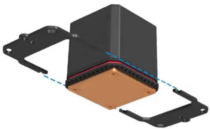
natural_image
3D rendering of a mechanical component with mounting flanges and a central copper-colored base (no text or symbols visible)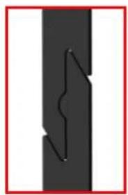
natural_image
Pure diagram of a vertical black bar with a zigzag line inside, no text or symbols presentnatural_image
3D rendering of a mechanical assembly with mounting base and clamping tool (no visible text or symbols)text_image
M4 UNC 6-32 10.5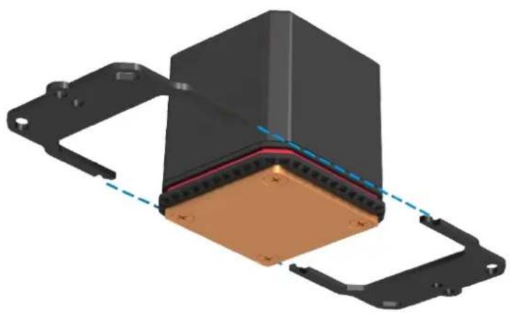
natural_image
3D rendering of a mechanical component with mounting flanges and a central copper-colored base (no text or symbols visible)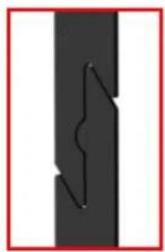
natural_image
Pure diagram of a vertical black bar with a zigzag line inside, no text or symbols presentnatural_image
3D rendering of a mechanical assembly with mounting base and internal components (no visible text or symbols)natural_image
Pure electrical connector diagram showing three black cable terminals connected by a blue arrow (no text or symbols)natural_image
Illustration of a C&C bottle pouring liquid into a funnel on a digital device (no text or symbols visible)OCOOL
https://www.alphacool.com
General Manager: Fabian Noelte