— Doorbells — Mode d'emploi PDF")
Video Doorbell Dual 2K (Wired) - Doorbells eufy - Free user manual and instructions
Find the device manual for free Video Doorbell Dual 2K (Wired) eufy in PDF.

| Product Type | Wired Video Doorbell |
| Brand | eufy |
| Model | TB200 (doorbell) / T8740 (electronic chime) |
| Video Resolution | 2K |
| Power Supply | 19V DC Power Adapter |
| Connectivity | 2.4 GHz Wi-Fi (via Eufy Security app) |
| Night Vision | Yes, with infrared LED |
| Audio | Doorbell with built-in electronic chime |
| App | Eufy Security (iOS and Android) |
| Installation | Wired, requires wall drilling for power cable routing |
| Recommended Mounting Height | 1.2 m from ground |
| Mounting Wedge | 15° included for angle adjustment |
| Compliance | Industry Canada CNR, Class B |
| RF Exposure Distance | Maintain a distance of 20 cm from body |
| Warranty | 12-month limited |
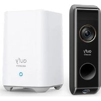
| Box Contents | Video doorbell, electronic chime, power adapter, mounting bracket, 15° mounting wedge, release pin, quick start guide, positioning card, screws |
| Compatibility | Does not work with existing chime |
| Connection Type | Screw terminals for power wire connection |
| Key Features | Live stream, doorbell notification, family sharing via app |
Frequently Asked Questions - Video Doorbell Dual 2K (Wired) eufy
User questions about Video Doorbell Dual 2K (Wired) eufy
0 question about this device. Answer the ones you know or ask your own.
Ask a new question about this device
Download the instructions for your Doorbells in PDF format for free! Find your manual Video Doorbell Dual 2K (Wired) - eufy and take your electronic device back in hand. On this page are published all the documents necessary for the use of your device. Video Doorbell Dual 2K (Wired) by eufy.
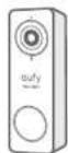
USER MANUAL Video Doorbell Dual 2K (Wired) eufy
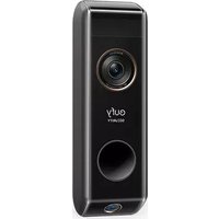
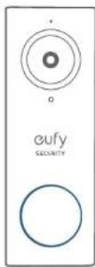
Video Doorbell 2K (Wired)
eufy SECURITY
natural_image
Line drawings of two eufy Security speakers, one with ventilation grille and the other with speaker tower (no text or symbols on devices)Anker Innovations Limited. All rights reserved.eufy Security and eufy Security Logo are trademarks of Anker Innovations Limited, registered in the United States and other countries. All other trademarks are the property of their respective owners.
51005002209 V02
English
Deutsch
Español
Français
Italiano
Nederlands
TABLE OF CONTENTS
What's Included
02
12
Running Wires through the Wall
How the System Works
03
13
Connecting the Wires
Getting Started
04
14
Hooking / Detaching the Doorbell
Setting Up the System
06
16
Powering on the Video Doorbell
Finding a Spot For Mounting
07
17
Notice
Installing the Mounting Bracket
||
105
Customer Service
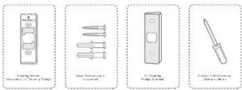
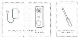
WHAT'S INCLUDED
For Video Doorbell Installation
Video Doorbell
2K (Wired)
Model: TB200
FCC ID: 2AOKB-T8200
IC: 23451-T8200
Screw Hole
Positioning Card
Mounting Bracket
(Attached to 15°
15° Mounting
Wedge (Optional)
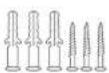
Screw Packs (Anchors are optional)

Doorbell
Detaching Pin
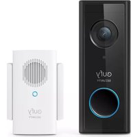
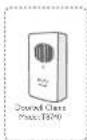
Doorbell Chime
Model: T8740

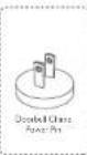
Doorbell Chime
Power Pin

Quick Start Guide

Indoor Power Adapter
Note:
• Doorbell chime power pin varies in different regions.
• Power adapter plug varies in different regions.
01 English English
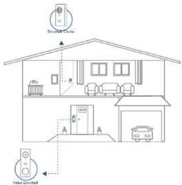
How the System Works
The video doorbell system includes 2 parts. One is the video doorbell at your porch. The other is the electronic chime plugged into an indoor power socket. The video doorbell is powered by the provided indoor power adapter, which requires the user to drill a hole in the external wall to run the power cord from indoors to outdoors.
The video doorbell doesn't work with the existing doorbell chime. Use the provided electronic chime instead. When someone rings the doorbell, people in the house will be notified.
Tips:
• To make the doorbell system work, running wires through the wall is required. You may need to hire a qualified electrician at your expense.
- The existing doorbell system is not compatible. If you have an existing doorbell button, remove it to avoid confusing visitors.
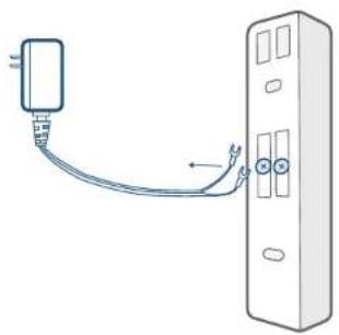
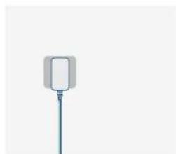
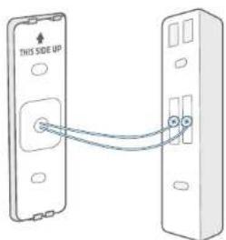
STEP I GETTING STARTED
Prepare the Video Doorbell for Installation
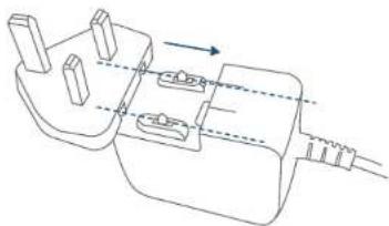
- Slide in the plug to the switching adapter until you hear a click.
natural_image
Technical line drawing of a mechanical component with internal parts and directional arrows (no text or symbols)- Connect the power adapter to the video doorbell.
03 English English
- Connect the provided power adapter to a power outlet preferably near the door. Wait for the video doorbell to power on.

- Align the doorbell chime power connector with the doorbell chime pin, and turn it clockwise until it locks in place.
STEP 2 SETTING UP THE SYSTEM
Set up the System
I. Download the Eufy Security App from the App Store or Google Play Store and install the App on your phone.


- Log into the Eufy Security App. Add your video doorbell (Wired) and scan the QR code for later installation process. QR code can be found on the back of the video doorbell and at the rear of the documentation box.
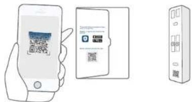
- Follow the on-screen instructions to connect the video doorbell to your home Wi-Fi, and complete the setup of the video doorbell. Then you can view live streams on the Eufy Security app. When you press the doorbell button, the provided electrical chime will sound a ringtone.
Note: If you want to share your video doorbell to your family members and let them operate the video doorbell via the Eufy Security App, go to Family & Guest from the App's side menu and follow the on-screen instructions to share your video doorbell.
05 English English
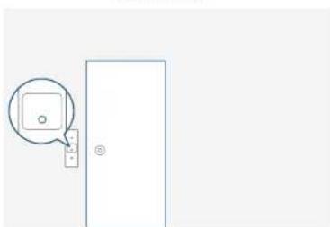
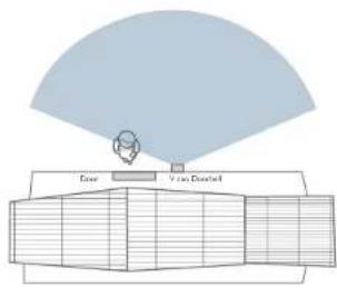
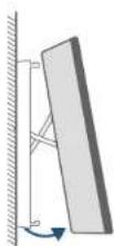
STEP 3 FINDING A SPOT FOR MOUNTING
Select Location and Height
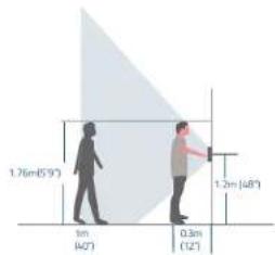
- Take the video doorbell outdoors with the power cord connected to it. It is safe to carry it around as the output is low voltage(19V DC).
- Try to find a location at your front door where you can get an ideal field of view on live stream. This is the location where you will mount the video doorbell. The recommended height for mounting is 48" (1.2 m) from the ground. If you want to place the doorbell close to a side wall, make sure the wall doesn't show up in the field of view. Installing the doorbell too close to a side wall will reflect IR light and make night vision blurry.
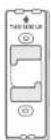
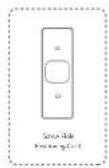
- Place the Screw Hole Positioning Card against the wall to mark the location for the power cord to run through the wall. Position the hole for the power cord to line up with the bottom half of the Positioning Card's square hole. Make sure this is where the wire will come out of.
What is required: Screw Hole Positioning Card
natural_image
Simple line drawing of a door with a speech bubble and a small icon, no text or symbols present.- Unplug the power adapter and detach the power adapter from the video doorbell.
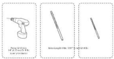
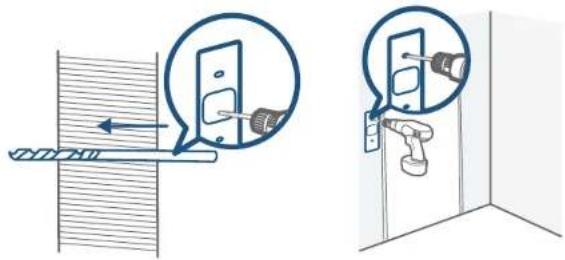
Drill Holes
- Drill a hole for the power cord to run through. Use a drill bit that is long enough to fully drill through the exterior wall.
2 Drill 2 holes to mount the mounting bracket. - If you are installing the mounting bracket on a wooden wall or board, DO NOT drill holes. You can screw in the wood directly.
- Anchors are needed if you are installing the mounting bracket on a wall that is made out of hard materials such as stucco, brick, or concrete.
- Drill on the screw hole positioning card with a 15/64" (6 mm) drill bit.
07 English English
What is required: Power Drill with 15/64" (6 mm) Drill Bit / Extra Long Drill Bit
Note:
- If you have problems with drilling holes yourself, have a qualified electrician do it. Make sure that you keep away from wires or pipes within the wall while drilling holes.
- If you have an existing doorbell button at the front door, remove it along with the wires to avoid confusing visitors by having 2 doorbells.
08
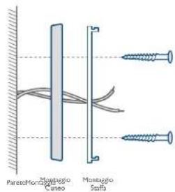
Use the 15° Mounting Wedge (Optional)
Use the 15^ mounting wedge as a supplementary mounting bracket if you wish to see more on a specific side.
Without 15° Mounting wedge
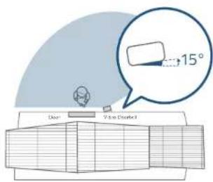
With 15 ^e Mounting wedge
09 English English
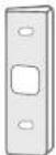
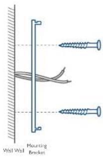
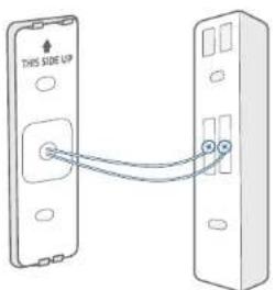
STEP 4 INSTALLING THE MOUNTING BRACKET
- Insert the two screws provided through the screw holes or through the 15^ mounting wedge (Install the mounting bracket to the 15^ mounting wedge in prior, using long screws).
- Fasten the screws into the wall tightly.
What is required: Mounting Bracket / Screw Packs / 15° Mounting Wedge (Optional) / Philips-Head Screwdriver
Without 15° Mounting Wedge
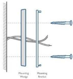
With 15° Mounting Wedge
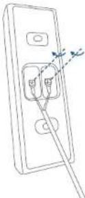
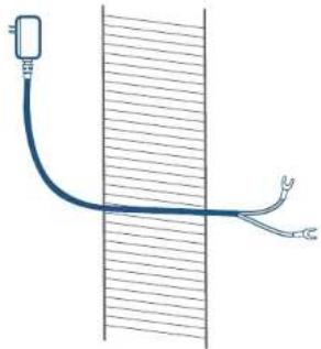
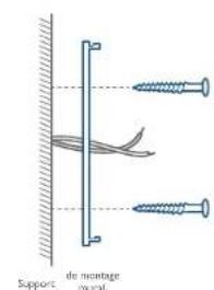
STEP 5 RUNNING WIRES THROUGH THE WALL
Run Wires through the Wall
I. Unplug the power adapter before running wires.
2. Unscrew the terminals on the back of the doorbell to detach the power cord.
natural_image
Diagram showing a cable being inserted into a device (no text or symbols present)- Slip down the grommet over the adapter wires.
- Run the power cord through the hole and carefully extend them outside.
natural_image
Diagram of a cable or wire penetration into a vertical channel, with no visible text or symbols.
• Make sure you have a qualified electrician run the wires if you are not comfortable with dealing with wires.
- Use the rubber plug or glue to fill the drill holes.
- Use the provided grommet to hold the wires into place. Make sure the wires are tucked neatly.
11 English English
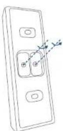
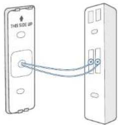
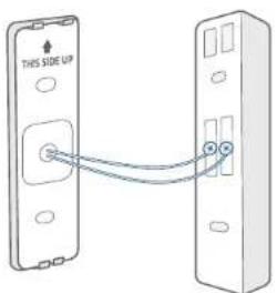
STEP 6 CONNECTING THE WIRES
Connect the Wires
Connect the wires to the two terminals at the back of the doorbell, then tighten the terminal screws. Wire can connect to any terminal.

- To prevent short-circuit, make sure the wires are not touching each other or crossing after connecting them to the terminals.
What is required: Power Adapter / Video doorbell / Philips-Head Screwdriver
13 English English
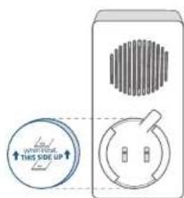
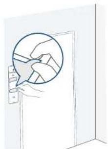
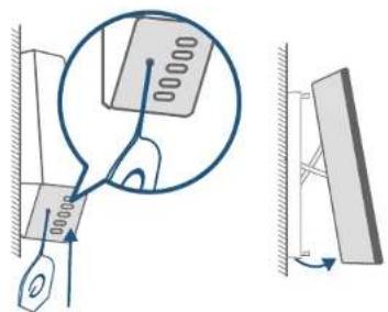
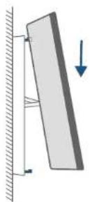
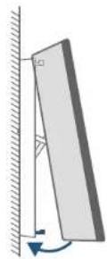
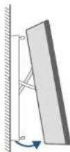
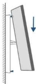
STEP 7 HOOKING / DETACHING THE DOORBELL
Hook the Doorbell on the Mounting Bracket
There are 2 thermal conductive pads on the mounting bracket. They're used to conduct heat from the video doorbell to the metal bracket.
I. Remove the films on the thermal conductive pads before you mount the doorbell.
2 Hook the doorbell on top of the mounting bracket.
3. Snap the doorbell bottom to the bracket and press it down until it clicks into place.
natural_image
Line drawing of a hand holding a door with a magnified inset showing hand positioning (no text or symbols)1
●
●

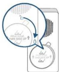
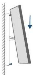
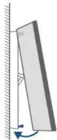
If the doorbell doesn't fit well, or you want to replace the doorbell, you can detach the doorbell.
Detach the Doorbell
- Use the doorbell detaching pin provided if you wish to detach the doorbell from the mounting bracket.
- Press and hold the hole on the bottom of the doorbell and then lift its bottom to take it off.
What is required: Doorbell detaching pin
natural_image
Diagram showing a mechanical linkage system with a magnified inset of a component (no text or symbols present)STEP 8 POWERING ON THE VIDEO DOORBELL
I. Plug the power adapter into the wall outlet indoors.
natural_image
Simple line drawing of a medical device with a vertical rod and rounded square body (no text or symbols)- Wait for the video doorbell to power up. The doorbell ring turns cyan. You can view the live stream shot from the video doorbell on the Eufy Security App.
For troubleshooting, check Help on the Eufy Security App.
15 English English
NOTICE
FCC Statement
This device complies with Part 15 of the FCC Rules. Operation is subject to the following two conditions: (1) this device may not cause harmful interference, and (2) this device must accept any interference received, including interference that may cause undesired operation.
Warning: Changes or modifications not expressly approved by the party responsible for compliance could void the user's authority to operate the equipment.
Note: This equipment has been tested and found to comply with the limits for a Class B digital device, pursuant to Part 15 of the FCC Rules. These limits are designed to provide reasonable protection against harmful interference in a residential installation.
This equipment generates uses and can radiate radio frequency energy and, if not installed and used in accordance with the instructions, may cause harmful interference to radio communications. However, there is no guarantee that interference will not occur in a particular installation. If this equipment does cause harmful interference to radio or television reception, which can be determined by turning the equipment off and on, the user is encouraged to try to correct the interference by one or more of the following measures: (1) Reorient or relocate the receiving antenna. (2) Increase the separation between the equipment and receiver. (3) Connect the equipment into an outlet on a circuit different from that to which the receiver is connected. (4) Consult the dealer or an experienced radio/ TV technician for help.
FCC Radio Frequency Exposure Statement
The device has been evaluated to meet general RF exposure requirements. The device can be used in fixed/mobile exposure condition. The min separation distance is 20cm.
Notice: Shielded cables
All connections to other computing devices must be made using shielded cables to maintain compliance with FCC regulations.
The following importer is the responsible party.
Company Name: POWER MOBILE LIFE, LLC
Address: 400 108th Ave NE Ste 400, Bellevue, WA 98004-5541
Telephone: I-800-988-7973
17 English English
CE This product complies with the radio interference requirements of the European Community.
Declaration of Conformity
Hereby, Anker Innovations Limited declares that this device is in compliance with the essential requirements and other relevant provisions of Directive 2014/53/EU. For the declaration of conformity, visit the Web site: https://www.eufylife.com/.
This product can be used across EU member states.
Do not use the Device in the environment at too high or too low temperature, never expose the Device under strong sunshine or too wet environment.
The suitable temperature for T8200 is -20°C-50°C.
The suitable temperature for T8740 is 0^ C- 45^ C.
RF exposure information: The Maximum Permissible Exposure (MPE) level has been calculated based on a distance of d=20 cm between the device and the human body. To maintain compliance with RF exposure requirement, use products that maintain a 20cm distance between the device and human body.
CAUTION RISK OF EXPLOSION IF BATTERY IS REPLACED BY AN INCORRECT TYPE. DISPOSE OF USED BATTERIES ACCORDING TO THE INSTRUCTIONS
Wi-Fi Operating Frequency Range: 2412\~2472MHz ; Wi-Fi Max Output Power:18.30 dBm
SUB-IG Frequency range:433.92 MHz; SUB-IG Output Power:7.407 dBm
Bluetooth Operating Frequency Range: 2402\~2480MHz; Bluetooth Max Output Power: 0.77 dBm The following importer is the responsible party (contact for EU matters only).
Importer: Anker Technology (UK) Ltd
Importer Address: Suite B, Fairgate House, 205 Kings Road, Tyseley, Birmingham, B11 2AA,
United Kingdom
This product is designed and manufactured with high quality materials and components, which can be recycled and reused.
This symbol means the product must not be discarded as household waste, and should be delivered to an appropriate collection facility for recycling. Proper disposal and recycling helps protect natural resources, human health and the environment. For more information on disposal and recycling of this product, contact your local municipality, disposal service, or the shop where you bought this product.
IC Statement
This device complies with Industry Canada licence-exempt RSS standard(s). Operation is subject to the following two conditions:
(1) this device may not cause interference, and
(2) this device must accept any interference, including interference that may cause undesired operation of the device."
This Class B digital apparatus complies with Canadian ICES-003.
When using the product, maintain a distance of 20cm from the body to ensure compliance with RF exposure requirements.
natural_image
Technical line drawing of a mechanical component with internal parts and directional arrows (no text or symbols)natural_image
Simple diagram of a balloon with a vertical line and a square body, no text or symbols present.
Deutsch 28
Hinweis:
natural_image
Diagram showing two screws attached to a vertical bar with coiled wires, no text or symbols presentDeutsch 30
natural_image
Diagram showing a cable being inserted into a device (no text or symbols present)natural_image
Diagram of a cable or wire penetration into a vertical wall, with no visible text or symbols.
33 Deutsch
natural_image
Illustration of a hand holding a door with a circular diagram overlay (no text or symbols)①

5

●

35 Deutsch
natural_image
Simple line drawing of a balloon with a vertical stick (no text or symbols)natural_image
Pure technical line drawing of a mechanical component with no text or symbolsnatural_image
Line drawings of two electrical outlet components with arrows indicating connection points (no text or symbols)natural_image
Simple line drawing of a vertical object with a handle and stem, no text or symbols present.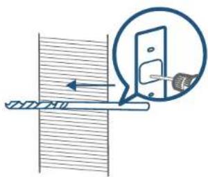
natural_image
Diagram showing a pipe connection with a magnified inset of a door and a tool (no text or symbols)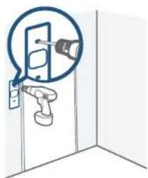
natural_image
Illustration of a door assembly with a tool and magnified detail showing a handle (no text or symbols)45 Español Español
Nota:
natural_image
Diagram showing a cable being inserted into a device (no text or symbols present)natural_image
Diagram of a cable or wire penetration into a vertical wall, showing two curved connectors (no text or symbols present)
PASO 7: MONTAJE Y DESMONTAJE DEL TIMBRE
natural_image
Line drawing of a door with a hand holding a small object, showing no text or symbols.①
●
●
PASO 8: ENCENDIDO DEL TIMBRE CON VÍDEO
natural_image
Simple 3D illustration of a cylindrical object with a stem, resembling a medical or laboratory device (no text or symbols)natural_image
Pure technical line drawing of a mechanical component with no text or symbolsnatural_image
Simple line drawing of a balloon with a square head and blue handle (no text or symbols)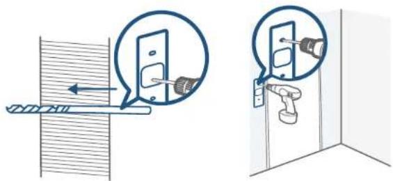
Remarque :
natural_image
Diagram showing a cable being inserted into a device (no text or symbols present)natural_image
Diagram of a cable or wire penetration into a vertical channel, with no visible text or symbols.
67 Français Français
ÉTAPE 7 RACCORDEMENT/ DÉBRANCHEMENT DE LA SONNETTE
natural_image
Simple line drawing of a door with a hand holding the left pan, showing hand positioning inside (no text or symbols)1
5

●

69 Français Français
ÉTAPE 8 MISE SOUS TENSION DE LA SONNETTE VIDÉO
natural_image
Simple line drawing of a balloon with a vertical stick (no text or symbols)natural_image
Pure technical line drawing of a mechanical component with no text or symbolsnatural_image
Line drawings of two electrical switch components with labeled terminals and connection arrows (no text or symbols)natural_image
Simple diagram of a rectangular object with a vertical line extending from its top, against a plain background (no text or symbols)natural_image
Simple line drawing of a door with a magnified inset showing a square detail (no text or symbols)Nota:
81 Italiano Italiano
PASSAGGIO 5 PASSAGGIO DEI FILI ATTRAVERSO LA PARETE
natural_image
Diagram showing a cable being inserted into a device (no text or symbols present)natural_image
Diagram of a cable or wire penetration into a vertical wall, with no visible text or symbols.
PASSAGGIO 7 AGGANCIO/DISTACCO DEL CAMPANELLO
natural_image
Line drawing of a door with a hand holding a small object, showing a circular diagram overlay (no text or symbols)1

●

●

PASSAGGIO 8 ACCENSIONE DEL VIDEOCITOFONO
natural_image
Technical line drawing of a mechanical component with internal parts and directional arrows (no text or symbols)natural_image
Simple line drawing of a balloon with a square head and blue handle (no text or symbols)Opmerking:
Met 15° montagewig
natural_image
Diagram showing a cable being inserted into a device (no text or symbols present)natural_image
Diagram of a cable or wire penetration into a vertical channel with two curved connectors (no text or symbols)

natural_image
Illustration of a hand holding a door with a circular diagram overlay (no text or symbols)①

5

●

natural_image
Simple line drawing of a medical device with a vertical rod and rounded square body (no text or symbols)12-month limited warranty
United States +1 (800) 968 7973 Mon-Fri 9AM-5PM (PT)
United Kingdom +41 (0) 1601 936 200 Mon-Fri 6AM-11AM (GMT)
Germany -49 (0) 69 9579 7960 Mo-Fr 6:00-11:00
- Email Us
Customer Support: support@eufylife.com
105
Anker Innovations Limited
Room 1318-19, Hollywood Plaza, 610 Nathan Road, Mongkok, Kowloon, Hong Kong
@EufyOfficial
@EufyOfficial
eufyofficial