C210 - Doorbells eufy - Free user manual and instructions
Find the device manual for free C210 eufy in PDF.
| Product Type | Video Doorbell |
| Brand | Eufy |
| Model | C210 (T8222) |
| Power Source | Rechargeable battery (USB 5V/1A charge) |
| Battery Life | Up to 4 months (depending on usage) |
| Video Resolution | 1080p |
| Night Vision | Yes (infrared LED) |
| Viewing Angle | Wide field of view (not specified) |
| Audio | Built-in microphone and speaker (two-way audio) |
| Motion Detection | Yes (PIR sensor) |
| Connectivity | Wi-Fi (2.4 GHz) |
| Mobile App | eufy Security (iOS/Android) |
| Storage | microSD card (not included) in the Wi-Fi chime |
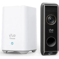
| Wi-Fi Chime Included | Yes (model T8020) |
| Box Contents | Video doorbell, Wi-Fi chime, USB cable, mounting bracket, 15° wedge, ejection pin, quick start guide |
| Weatherproof | Weather-resistant (not specified, suitable for outdoor use) |
| Operating Temperature | Not specified (standard outdoor use) |
| Weight | Not specified |
| Dimensions | Not specified |
| Care and Cleaning | Clean with a soft, dry cloth. Avoid chemical products. |
| Safety | Compliant with FCC and IC standards. RF safety distance: 20 cm. |
| Repairability | Battery not user-replaceable. No official spare parts listed. |
Frequently Asked Questions - C210 eufy
User questions about C210 eufy
0 question about this device. Answer the ones you know or ask your own.
Ask a new question about this device
Download the instructions for your Doorbells in PDF format for free! Find your manual C210 - eufy and take your electronic device back in hand. On this page are published all the documents necessary for the use of your device. C210 by eufy.
USER MANUAL C210 eufy
Anker Innovations Limited. All rights reserved eufy Security and eufy Security Logo are trademarks of Anker Innovations Limited, registered in the United States and other countries. All other trademarks are the property of their respective owners.
51005002472 V01
eufy SECURITY
QUICK START GUIDE
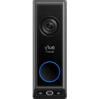
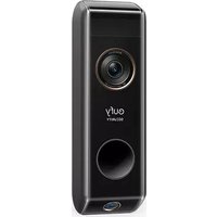
Video Doorbell 1080p (Battery-Powered)
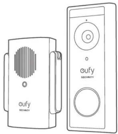
natural_image
Line drawings of two eufy Security devices, one with a circular vent and the other with a circular button (no text or symbols on the devices themselves)English 01
Deutsch 20
Español 37
Français 54
Italiano 71
Nederlands 88
Português 105
لعربيية 122
TABLE OF CONTENTS
What's Included 01 09 Finding a Mounting Spot Product Overview 03 11 Mounting the Bracket How the System Works 04 14 Mounting the Doorbell Powering on the Wi-Fi Doorbell Chime 05 15 Detaching the Doorbell Setting up the System 07 16 Recharging the Doorbell Charging Your Doorbell 08 17 Notice
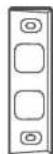
WHAT'S INCLUDED
For Video Doorbell Installation
Video Doorbell (1080p, Battery-Powered) Model: T8222
FCC ID: 2AOKB-T8220 IC: 23451-T8220

USB Charging Cable
Mounting Bracket
Screw Hole Positioning Card
15° Mounting Wedge (Optional)
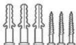
Screw Packs (Spare screws and anchors are included)
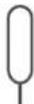
Doorbell Detaching Pin
Quick Start Guide
For Wi-Fi Doorbell Chime Installation
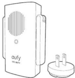
natural_image
Line drawing of a dual-chamber electronic device with ventilation grille and terminal socket (no text or symbols)Model: Wi-Fi Doorbell Chime
Power Plug
FCC ID: 2AOKB-T8020
IC: 23451-T8020
Note: Power plug may vary in different regions.
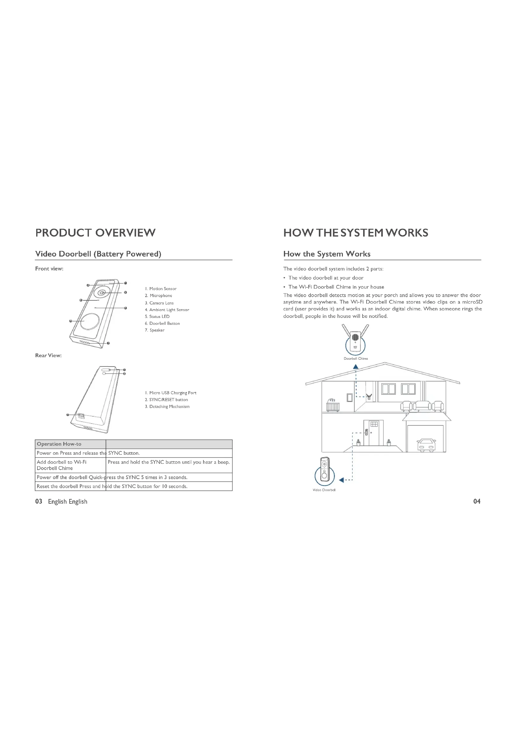
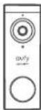
PRODUCT OVERVIEW
Video Doorbell (Battery Powered)
Front view:
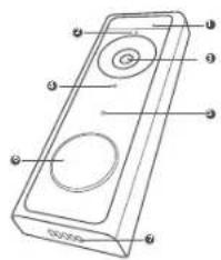
text_image
Diagram of a handheld device with labeled ports and circular ports, showing internal structure and mounting points.- Motion Sensor
- Microphone
- Camera Lens
- Ambient Light Sensor
- Status LED
- Doorbell Button
- Speaker
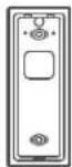
Rear View:
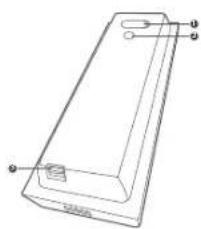
natural_image
Line drawing of a rectangular electronic device with labeled ports (no text or symbols present)I. Micro USB Charging Port
2. SYNC/RESET button
3. Decaching Mechanism
| Operation How-to | |
| Power on Press and release the SYNC button. | |
| Add doorbell to Wi-Fi Doorbell Chime | Press and hold the SYNC button until you hear a beep. |
| Power off the doorbell Quick-press the SYNC 5 times in 3 seconds. | |
| Reset the doorbell Press and hold the SYNC button for 10 seconds. | |
03 English English
How the System Works
The video doorbell system includes 2 parts:
• The video doorbell at your door
• The Wi-Fi Doorbell Chime in your house
The video doorbell detects motion at your porch and allows you to answer the door anytime and anywhere. The Wi-Fi Doorbell Chime stores video clips on a microSD card (user provides it) and works as an indoor digital chime. When someone rings the doorbell, people in the house will be notified.
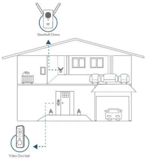
text_image
Doorbell Chimo Video DoorbellSTEP I POWERING ON THE WI-FI DOORBELL CHIME
Connect the Wi-Fi Doorbell Chime to the Internet
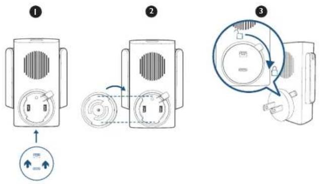
I. Fix the power connector to Wi-Fi Doorbell Chime.
① Place the power connector over Wi-Fi Doorbell Chime in the direction the arrows indicate.
② Align the raised slots of the power connector with the notch on the base of the doorbell chime.
③ Rotate clockwise to lock the power connector in place.
text_image
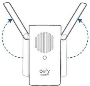
Diagram showing three-step installation of a device with labeled parts and directional arrows indicating motion.2 Extend Wi-Fi Doorbell Chime's antennas.
text_image
eufy SECURITY- Plug Wi-Fi Doorbell Chime into an AC power supply at your desired location. The LED indicator turns solid green when the doorbell chime is ready for setup.
STEP 2 SETTING UP THE SYSTEM
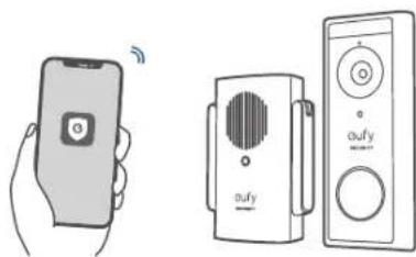
Download the App and Set up the System
Download the eufy Security app from the App Store (iOS devices) or Google Play (Android devices).


Sign up for a eufy Security account and follow onscreen instructions to complete the setup.
Tap Add Device and add the following devices:
I. Add the Wii-Fi Doorbell Chime.
2. Add the doorbell.
natural_image
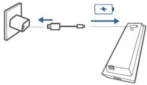
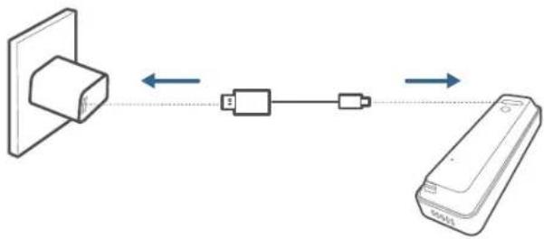
Illustration of a hand holding a smartphone and two connected devices with audio equipment (no text or symbols)STEP 3 CHARGING YOUR DOORBELL
The doorbell comes with an 80% battery level for safe transportation. Fully charge it before mounting the doorbell at your front door.
text_image
Diagram showing connection between a device with battery and power supply, including bidirectional arrows and component labelsNote: The battery life varies depending on usage. In most common cases, a doorbell may have up to 15 events per day and each recording lasts 20 seconds on average. Under this scenario, the doorbell battery life can last up to 4 months.
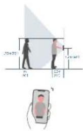
STEP 4 FINDING A MOUNTING SPOT
Find a Mounting Spot
Take the Video Doorbell to your front door and check the live view on the eufy Security app at the same time. Find a position where you can get the desired field of view.
Consider the below factors:
- Check if you can reuse the existing holes and anchors on the wall or door frame.
- If you want to place the doorbell close to a side wall, make sure the wall doesn't show up in the field of view. Otherwise IR light will be reflected and night vision will become blurry.
- If you are drilling the mounting holes for the first time the recommended mounting height is 48" / 1.2m from the ground.
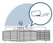
- Use the 15^ mounting wedge as a supplementary mounting bracket if you wish to see more on a specific side.
text_image
20m 30m 40m 50m 60m 70m 80m 90m 100m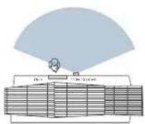
Without 15° Meeting gauge
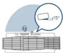
text_image
15° Top Top to BottomWith 15° Morning wedge
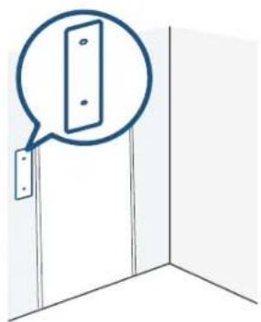
Place the Screw Hole Positioning Card against the wall to mark the position.
natural_image
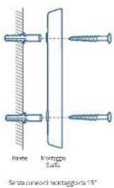
Simple line drawing of a door corner with a speech bubble highlighting the door (no text or symbols)STEP 5 MOUNTING THE BRACKET
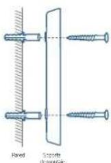
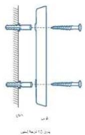
Mount the Doorbell on a Wooden Surface
If you're mounting the doorbell on a wooden surface, you don't need to pre-drill pilot holes. Use the provided screws to secure the Mounting Bracket on the wall. The Screw Hole Positioning Card indicates the position of the screw holes.
What is required: Power Drill, Mounting Bracket, 15° Mounting Wedge (Optional), Screw Packs
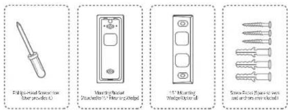
text_image
Fellips-Head Screwdriver User provides L0 Mounting Bracket PushelButton to 15" Mounting Wedge 15" Mounting Wedge Optimal Screw Fastener (Spas for press and from an electric wall)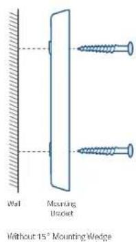
text_image
Wall Mounting Bracket Without 15" Mounting Wedge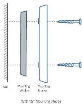
text_image
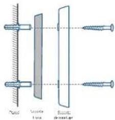
Wall Mounting Wedge Mounting Bracket With 15° Mounting Wedge11 English English
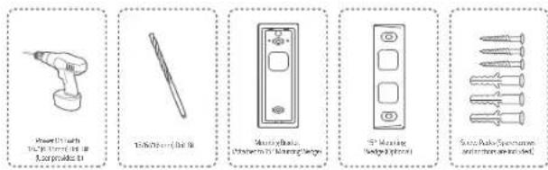
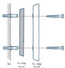
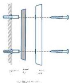
Mount the Video Doorbell on Surfaces Made Out of Hard Materials
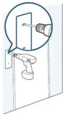
- If you're mounting the doorbell on a surface made out of hard materials, like brick, concrete, stucco, drill 2 holes through the Screw Hole Positioning Card with 15/64"(6mm) drill bit.
- Insert the provided anchors, and then use the provided long screws to secure the Mounting Bracket on the wall.
What is required: Power Drill, 15/64"(6mm) Drill Bit, Mounting Bracket, 15° Mounting Wedge (Optional), Screw Packs
text_image
Power tools 100% charged 150% Lampade 15 100% charged 150% Switchable Switch to 150% charged 150% Switchable Switch to 150% charged 150% Switchable Switch to 150% charged 150%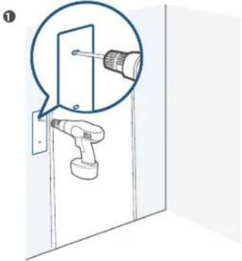
natural_image
Diagram showing a screwdriver inserted into a door panel, with no text or symbols present②

text_image
Wall Mounting BracketWhale 15' Mounting Wedge
text_image
Close-up Close-up Close-upWith 15" Mounting Wedge
STEP 6 MOUNTING THE DOORBELL
Mount the Doorbell
Align the doorbell with the top of the mount and then snap the bottom into place.

natural_image
Two technical diagrams showing a structural component with directional arrows indicating rotation or movement (no text or symbols present)You're all set!
If you want to detach the doorbell or recharge it, please refer to the following sections.
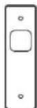
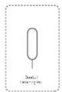
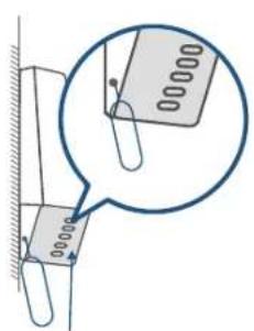
APPENDIX I DETACHING THE DOORBELL
Detach the Doorbell
I. Use the doorbell detaching pin provided if you wish to detach the doorbell from the Mounting Bracket.
2. Insert and press the detaching pin into the hole on the bottom of the doorbell and then lift to take the bottom of the doorbell off.
What is required: Doorbell Detaching Pin
text_image
Technical diagram showing a magnified view of a component with dimension annotations and a magnified detail view.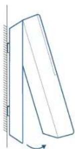
natural_image
Simple line drawing of a tilted rectangular object with an arrow indicating rotation, mounted on a vertical surface (no text or symbols)APPENDIX 2 RECHARGING THE DOORBELL
Recharge the Doorbell
Charge the doorbell with universal USB chargers that deliver 5V IA output.
flowchart
graph LR
    A["Device with cable"] <--> B["USB Cable"]
    B <--> C["Remote"]
| LED indication | Charging: Solid orange |
| Fully charged: Solid blue | |
| Charging time 6 hours from | 0% to 100% |
NOTICE
FCC Statement
This device complies with Part 15 of the FCC Rules. Operation is subject to the following two conditions: (1) this device may not cause harmful interference, and (2) this device must accept any interference received, including interference that may cause undesired operation.
Warning: Changes or modifications not expressly approved by the party responsible for compliance could void the user's authority to operate the equipment.
Note: This equipment has been tested and found to comply with the limits for a Class B digital device, pursuant to Part 15 of the FCC Rules. These limits are designed to provide reasonable protection against harmful interference in a residential installation.
This equipment generates uses and can radiate radio frequency energy and, if not installed and used in accordance with the instructions, may cause harmful interference to radio communications. However, there is no guarantee that interference will not occur in a particular installation. If this equipment does cause harmful interference to radio or television reception, which can be determined by turning the equipment off and on, the user is encouraged to try to correct the interference by one or more of the following measures: (1) Reorient or relocate the receiving antenna. (2) Increase the separation between the equipment and receiver. (3) Connect the equipment into an outlet on a circuit different from that to which the receiver is connected. (4) Consult the dealer or an experienced radio / TV technician for help.
FCC Radio Frequency Exposure Statement
The device has been evaluated to meet general RF exposure requirements. The device can be used in fixed/mobile exposure condition. The min separation distance is 20cm.
Notice: Shielded cables
All connections to other computing devices must be made using shielded cables to maintain compliance with FCC regulations.
The following importer is the responsible party:
Company Name: POWER MOBILE LIFE, LLC
Address: 400 108th Ave NE Ste 400, Bellevue, WA 98004-5541
Telephone: 1-800-988-7973
CE This product complies with the radio interference requirements of the European Community.
Declaration of Conformity
Hereby, Anker Innovations Limited declares that this device is in compliance with the essential requirements and other relevant provisions of Directive 2014/53/EU. For the declaration of conformity, visit the Web site: https://www.eufylife.com/.
This product can be used across EU member states.
Do not use the Device in the environment at too high or too low temperature, never expose the Device under strong sunshine or too wet environment.
The suitable temperature for T8020 and accessories is 0^ C- 40^ C.
The suitable temperature for T8222 is -20°C-50°C.
When charging, please place the device in an environment that has a normal room temperature and good ventilation.
It is recommended to charge the device in an environment with a temperature that ranges from 5^ C\~ 25^ C.
RF exposure information: The Maximum Permissible Exposure (MPE) level has been calculated based on a distance of d=20 cm between the device and the human body. To maintain compliance with RF exposure requirement, use product that maintains a 20cm distance between the device and human body.
CAUTION RISK OF EXPLOSION IF BATTERY IS REPLACED BY AN INCORRECT TYPE. DISPOSE OF USED BATTERIES ACCORDING TO THE INSTRUCTIONS Wifi Operating Frequency Range: 2412\~2472MHz (2.4G)
Wifi Max Output Power: 15.68dBm (ERIP for T8020); 15.01dBm (ERIP for T8222)
Bluetooth Operating Frequency Range: 2402\~2480MHz; Bluetooth Max Output Power: 2.048dBm (EIRP)
The following importer is the responsible party (contact for EU matters only)
Anker Technology (UK) Ltd, Suite B, Fairgate House, 205 Kings Road, Tyseley, Birmingham, B11 2AA, United Kingdom

This product is designed and manufactured with high quality materials and components, which can be recycled and reused.

This symbol means the product must not be discarded as household waste, and should be delivered to an appropriate collection facility for recycling. Proper disposal and recycling helps protect natural resources, human health and the environment. For more information on disposal and recycling of this product, contact your local municipality, disposal service, or the shop where you bought this product.
IC Statement
This device complies with Industry Canada licence-exempt RSS standard(s). Operation is subject to the following two conditions:
(1) this device may not cause interference, and
(2) this device must accept any interference, including interference that may cause undesired operation of the device."
This Class B digital apparatus complies with Canadian ICES-003.
When using the product, maintain a distance of 20cm from the body to ensure compliance with RF exposure requirements.
natural_image
Line drawing of a dual-chamber security device with ventilation grille and two terminal blocks (no text or symbols)text_image
Diagram showing three-step installation of a device with labeled components and directional arrows indicating motion.natural_image
Illustration of a hand holding a smartphone and two connected devices with audio equipment (no text or symbols)text_image
Diagram showing connection between a device with battery and power supply, including bidirectional arrows and component labelsnatural_image
Simple line drawing of a door corner with a speech bubble highlighting the door panel (no text or symbols)text_image
Diagram showing a screwdriver inserted into a door panel, with a magnified view highlighting the component.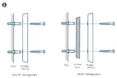
natural_image
Two technical diagrams showing a structural component with an upward arrow and a curved arrow indicating rotation (no text or symbols present)Das war's!
text_image
Technical diagram showing a magnified view of a component with dimension annotations and a magnified detail view.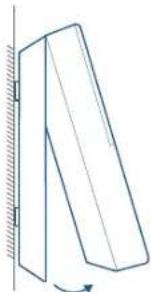
natural_image
Simple line drawing of a tilted rectangular object with a curved arrow indicating rotation (no text or symbols)ANHANG 2 – AUFLADEN DER TÜRKLINGEL
flowchart
graph LR
    A["Device with top block"] <--> B["Device with left block"]
    B <--> C["Device with right block"]
    D["Mobile Device"] -->|Data Flow| A
    D -->|Data Flow| C
natural_image
Line drawing of a rectangular electronic device with ports and connectors (no text or symbols)text_image
Diagram illustrating three-step device operation: adding a fan to a speaker, rotating the speaker with a circular dial, and finally adjusting the speaker's dial.natural_image
Illustration of a hand holding a smartphone and two connected devices with sound waves (no text or symbols)PASO 3: CARGA DEL TIMBRE
text_image
Diagram showing connection between a power outlet, switch, and battery with bidirectional arrows indicating signal flow.natural_image
Simple line drawing of a door with a speech bubble highlighting the door (no text or symbols)natural_image
Diagram of a hand tool inserting into a door, with a magnified inset showing the tool's tip (no text or symbols present)49
Español Español
2
Sin cuftade mortgage de 15°
text_image
Tuned Vaporate Bottlenatural_image
Two technical line drawings of a folded panel or support structure with directional arrows indicating movement (no text or symbols)¡Ya está!
text_image
Technical diagram showing a magnified view of a component with dimension annotations and a magnified detail view.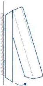
natural_image
Simple line drawing of a tilted rectangular object with a curved arrow indicating rotation (no text or symbols)natural_image
Line drawing of a security device with two terminal blocks (no text or symbols)natural_image
Technical line drawing of a rectangular electronic device with labeled ports (no text or symbols present)text_image
Diagram showing three-step installation of a device with labeled components and directional arrows indicating motion.natural_image
Diagram of a dual-band RF device labeled 'eufy SECURITY' with no visible text or symbols beyond the label.text_image
Diagram showing a smartphone connected to a speaker and a remote control unit, both labeled with 'afy' and signal icons.ÉTAPE 3 CHARGEMENT DE VOTRE SONNETTE
text_image
Diagram showing connection between a device with battery and power supply, including bidirectional arrows and component labels.natural_image
Simple line drawing of a door with a speech bubble highlighting a panel (no text or symbols)ÉTAPE 5 MONTAGE DU SUPPORT
text_image
Power transformer in 500mm x 100g 4.5V DC 1.5V M260 mm x 100A Capacitor box polarized terminal (100V) Cathode, 15Ω polarized Pumpable and voltage on screen①
natural_image
Diagram of a door with a screwdriver inserted, showing mechanical components (no text or symbols)
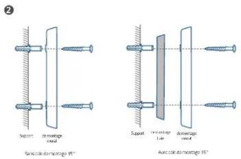
ÉTAPE 6 MONTAGE DE LA SONNETTE
Monter la sonnette
natural_image
Two mechanical diagrams showing a tilted panel with an upward arrow and a curved arrow indicating rotation (no text or symbols)text_image
Technical diagram showing a magnified view of a component with dimension annotations and a magnified detail view.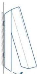
natural_image
Simple line drawing of a tilted rectangular object with a curved arrow indicating rotation (no text or symbols)ANNEXE 2 RECHARGEMENT DE LA SONNETTE
natural_image
Line drawing of a security device with two pins and a label 'oufy SECURITY' (no additional text or symbols)text_image
Diagram of a handheld device with labeled parts, showing front, back, and top views with numbered annotations.natural_image
Line drawing of a rectangular electronic device with labeled ports (no text or symbols present)text_image
Diagram of a device with labeled components and directional arrows indicating movement or flow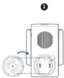
natural_image
Diagram of a device with circular components and a rotating arrow, no text or symbols present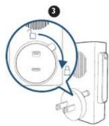
natural_image
Diagram of a device with a magnified circular component and pointer, no visible text or symbolsnatural_image
Illustration of a hand holding a smartphone and two connected devices with sound waves (no text or symbols)PASSAGGIO 3 RICARICA DEL CITOFONO
text_image
Diagram showing connection between a device and a battery, with bidirectional arrows indicating signal flow.natural_image
Simple line drawing of a door with a speech bubble highlighting the door (no text or symbols)PASSAGGIO 5 MONTAGGIO DELLA STAFFA
Montaggio del citofono su una superficie lignea
natural_image
Diagram of a screwdriver inserted into a door, showing the tool and component (no text or symbols present)2
natural_image
Two technical diagrams showing a structural component under axial compression, with directional arrows indicating motion (no text or symbols present)text_image
Technical diagram showing a magnified view of a paperclip with dimension labels and a magnified inset highlighting the measurement.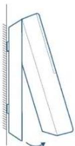
natural_image
Simple line drawing of a tilted rectangular object with an arrow indicating rotation (no text or symbols)APPENDICE 2 RICARICA DEL CITOFONO
natural_image
Line drawing of a security device with ventilation grille and two terminal blocks (no text or symbols)Model: Wifi-deurbelgong FCC-ID: 2AOKB-T8020 IC: 23451-T8020
Stekker
text_image
Diagram of a handheld device with numbered components for identificationnatural_image
Line drawing of a rectangular electronic device with labeled ports (no text or symbols)I. Micro-USB-oplaadpoort
2. SYNC/RESET-knop
3. Loskoppelmechanisme
text_image
Diagram illustrating three-step installation of a device with labeled components and directional arrows indicating movement.natural_image
Illustration of a smartphone with wireless signal and two connected devices (no text or symbols)STAP 3 UW DEURBEL OPLADEN
text_image
Diagram showing connection between a wall socket and a battery via USB cable, with bidirectional arrows indicating data flow.text_image
1.5m (m) 2.5m 3.5m 4.5m 5.5m 6.5m 7.5m 8.5m 9.5m 10.5m 11.5m 12.5m 13.5m 14.5m 15.5m 16.5m 17.5m 18.5m 19.5m 20.5m 21.5m 22.5m 23.5m 24.5m 25.5m 26.5m 27.5m 28.5m 29.5m 30.5m 31.5m 32.5m 33.5m 34.5m 35.5m 36.5m 37.5m 38.5m 39.5m 40.5m 41.5m 42.5m 43.5m 44.5m 45.5m 46.5m 47.5m 48.5m 49.5m 50.5m 51.5m 52.5m 53.5m 54.5m 55.5m 56.5m 57.5m 58.5m 59.5m 60.5m 61.5m 62.5m 63.5m 64.5m 65.5m 66.5m 67.5m 68.5m 69.5m 70.5m 71.5m 72.5m 73.5m 74.5m 75.5m 76.5m 77.5m 78.5m 79.5m 80.5m 81.5m 82.5m 83.5m 84.5m 85.5m 86.5m 87.5m 88.5m 89.5m 90.5m 91.5m 92.5m 93.5m 94.5m 95.5m 96.5m 97.5m 98.5m 99.5m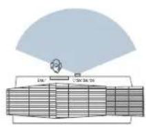
flowchart
graph TD
    A["Central Server"] --> B["Data Unit 1"]
    A --> C["Data Unit 2"]
    A --> D["Data Unit 3"]
    A --> E["Data Unit 4"]
    A --> F["Data Unit 5"]
    A --> G["Data Unit 6"]
    A --> H["Data Unit 7"]
    A --> I["Data Unit 8"]
    A --> J["Data Unit 9"]
    A --> K["Data Unit 10"]
7016 15° martagesig.
text_image
15°Hist 15° mar bagesig,
natural_image
Simple line drawing of a door with a speech bubble highlighting a panel (no text or symbols)STAP 5 DE BEUGEL MONTEREN
natural_image
Diagram of a robotic arm holding a door, with a magnified inset showing the tool (no text or symbols present)②
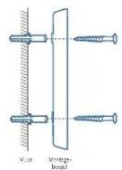
text_image
Muir Montzugs- bogelZander 15° montegeve
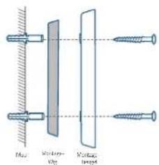
text_image
Lens Screen Screen lensMet 15 ^m montage wie
STAP 6 DE DEURBEL MONTEREN
De deurbel monteren
natural_image
Diagram showing two mechanical or structural configurations with directional arrows, no text or symbols present.U bent klaar!
text_image
Technical diagram showing a magnified view of a component with labeled parts and a magnified inset highlighting the part number '000000'.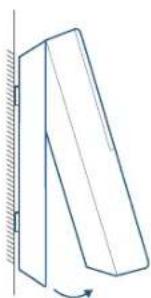
natural_image
Simple line drawing of a tilted rectangular object with an arrow indicating rotation, mounted on a vertical surface (no text or symbols)BIJLAGE 2 DE DEURBEL OPLADEN
De deurbel opladen
flowchart
graph LR
    A["Device with 3D block"] <--> B["Device connected via solid line"]
    B <--> C["Remote Control Unit"]
natural_image
Line drawing of a smart home control unit with ventilation grille and two terminal blocks (no text or symbols)Modelo: Campainha por Wi-Fi
Ficha de alimentação
ID da FCC: 2AOKB-T8020
IC: 23451-T8020
text_image
Diagram of a handheld device with labeled parts, showing front, back, and top views with numbered annotations.natural_image
Technical line drawing of a rectangular electronic component with mounting holes and a base (no text or symbols)text_image
Diagram showing a device with labeled components and directional arrows indicating movement or operation.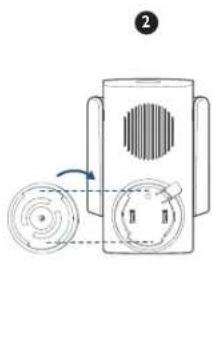
natural_image
Diagram of a device with circular components and a rotating arrow, no text or symbols present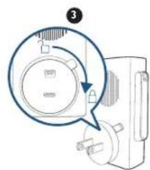
natural_image
Diagram of a device with a magnified circular detail and pointer, no visible text or symbolsnatural_image
Diagram of a dual-band RF device with eufy Security label, showing two blades and a central speaker (no text or symbols beyond branding)natural_image
Illustration of a smartphone with wireless signal and two connected devices (no text or symbols)PASSO 3 CARREGAR A CAMPAINHA
text_image
Diagram showing connection between a device and a battery, with bidirectional arrows indicating data flow.natural_image
Simple line drawing of a door with a speech bubble highlighting the door (no text or symbols)PASSO 5 INSTALAR O SUPORTE
text_image
Irruption tool Irruption tool (2.5 mm) Oscillator Irruption tool (2.5 mm) Oscillator (2.5 mm) Oscillator (2.5 mm) 150 mm Cathaloporous Anti-dominant tool Pentose and spase Oscillator (2.5 mm)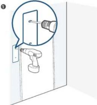
text_image
Diagram showing a screwdriver inserted into a door panel, with a magnified view highlighting the component.natural_image
Two technical line drawings of a structural component with directional arrows indicating motion (no text or symbols)Está pronta!
text_image
Diagram showing a magnified view of a paperclip with measurement markings, likely illustrating a measurement or inspection process.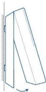
natural_image
Simple line drawing of a tilted rectangular object with an arrow indicating rotation, no text or symbols present.ANEXO 2 RECARREGAR A CAMPAINHA
Recarregar a campainha
flowchart
graph LR
    A["Device with top block"] <--> B["Device with left block"]
    B <--> C["Remote Device"]
natural_image
Line drawing of a Security eufy device with two terminal blocks (no text or symbols on the device itself)text_image
Technical diagram of a remote control device with numbered components for identificationnatural_image
Line drawing of a rectangular electronic device with labeled ports (no text or symbols present)BSU orciM 1. ملذ شح
text_image
Diagram showing a device with ventilation slots and a circular button labeled with directional arrows, likely indicating a process or system.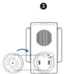
natural_image
Diagram of a device with circular components and a rotating arrow, no text or symbols present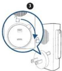
text_image
Diagram showing a device with a magnified circular component and an arrow indicating rotation or adjustment.natural_image
Diagram of a dual-band RF device labeled 'eufy RECINIT' with no visible text or symbols beyond the label.text_image
Diagram showing a smartphone with wireless signal and two connected devices labeled 'oufy' with speaker and control buttons.text_image
Diagram showing connection between a wall socket and a remote device via battery, with bidirectional arrow indicating signal flow.natural_image
Simple line drawing of a door corner with a magnified inset showing a rectangular panel (no text or symbols)natural_image
Diagram of a screwdriver inserted into a door, showing mechanical assembly (no text or symbols)②
text_image
100%10.5
natural_image
Two schematic diagrams showing a structural component under axial tension, with directional arrows indicating rotation (no text or symbols present)كل شي: جاهز للعمل!
text_image
Technical diagram showing a magnified view of a component with dimension annotations and a magnified inset highlighting the measurement.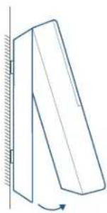
natural_image
Simple line drawing of a tilted rectangular object with a curved arrow indicating rotation (no text or symbols)12-month limited warranty
12 Monate eingeschränkte Garantie | Garantía limitada de 12 meses
Garantie limitée de 12 mois | Garanzia limitata di 12 mesi | 12 maanden beperkte garantie
(US) +1 (800) 988 7973 Mon-Fri 9:00-17:00 (PT)
(UK) + 44 (0) 1604 936 200 Mon-Fri 6:00-11:00 (GMT)
(DE) +49 (0) 69 9579 7960 Mon-Fri 6:00-11:00

+971 42463266 (Middle East & Africa) Sun-Thu 9:00 - 17:30 (GMT+4)
+971 8000320817 (UAE) Sun-Thu 9:00 - 17:30 (GMT+4)
+966 8008500030 (KSA) Sun-Thu 8:00 - 16:30 (GMT+3)
+965 22069086 (Kuwait) Sun-Thu 8:00 - 16:30 (GMT+3)

Customer Support: support@eufylife.com
Anker Innovations Limited
Room 1318-19, Hollywood Plaza, 610 Nathan Road, Mongkok, Kowloon,
Hong Kong

@EufyOfficial

@EufyOfficial

eufyofficial