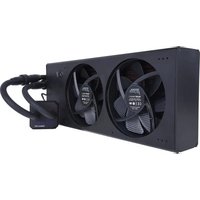
Eiszeit 2000 Chiller - Computer cooling system Alphacool - Free user manual and instructions
Find the device manual for free Eiszeit 2000 Chiller Alphacool in PDF.


User questions about Eiszeit 2000 Chiller Alphacool
0 question about this device. Answer the ones you know or ask your own.
Ask a new question about this device
Download the instructions for your Computer cooling system in PDF format for free! Find your manual Eiszeit 2000 Chiller - Alphacool and take your electronic device back in hand. On this page are published all the documents necessary for the use of your device. Eiszeit 2000 Chiller by Alphacool.
USER MANUAL Eiszeit 2000 Chiller Alphacool
Parameter Adjustment 8-11
Flow Alarm 12
Fault Indication
Technical Specification 15
German Manual 17
French Manual
Security Advice
Please ensure the power supply and electrical outlet are securely connected and that the grounding wire is connected.
The average operating current of the chiller is small, but the instantaneous operating current could be up to 10 amps.
Please make sure there is a stable and normal voltage for the working chiller!
The standard operating voltage for the chiller is 220 V.
Mismatched power frequency can cause damage to the chiller!
Be sure you can run a machine with 50 Hz.
To protect the pump, it is strongly advised that you do not run the chiller without having water in the water reservoir!
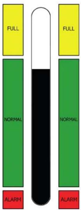
The machine is packaged without water in the tank, so make sure the tank has enough water inside before starting it otherwise the pump can be damaged. When the water level is below the green (NORMAL) range of the water level gauge, the cooling capacity of our chiller will go down slightly, hence please ensure the water level is within the green (NORMAL) range. Do not drain the water by circulating the pump!
Please be sure that the air inlet and air outlet have good ventilation!
There must be at least 30 cm from obstructions to the air outlet in the back of the cooler and at least 8 cm between obstructions and the side air inIet.
The fi Iter screen must be regularly cleaned!
It's essential to unpick and clean the dust gauze, or a serious blockage could cause a breakdown to the chiIler.
Please pay attention to the effect of the condensate water!
When there is higher ambient humidity, and when the water temperature is lower than the ambient temperature, condensation will appear on the surface of the water circulation pipes and the cooled components. If this occurs, setting a higher water temperature or keeping connected pipes and cooled parts warm is recommended.
Parts Introduction
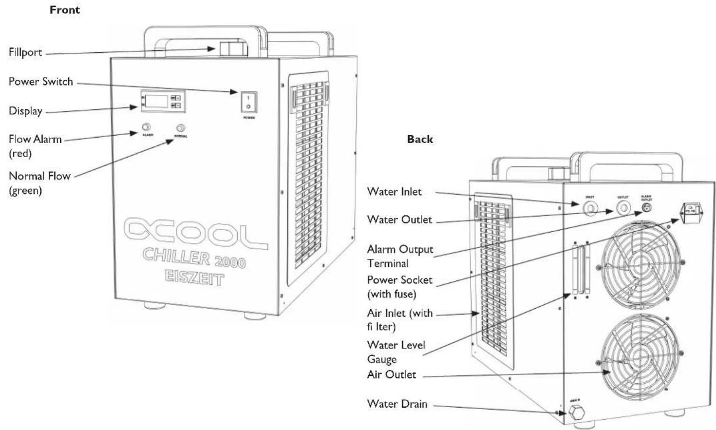
text_image
Front Fillport Power Switch Display Flow Alarm (red) Normal Flow (green) CCOOL CHILLER 2000 EISZEIT Back Water Inlet Water Outlet Alarm Output Terminal Power Socket (with fuse) Air Inlet (with fi Iter) Water Level Gauge Air Outlet Water DrainInstallation
Open the Fillport to fill in cooling water
Keep observing the water level gauge while adding water slowly. For the cooling of carbon steel equipment, the water should be added an appropriate amount of anti-corrosion additives. Working in cold areas, it's better to use noncorrosive antifreeze fluid.
Connect the water in- and outlet to your cooling circuit Use two GI/4 fi ttings to connect the chiller with tubes.
Plug in power, turn on the power switch
Do not start up without water in the water reservoir!
- The first time of operating may cause more bubbles in the tube leading to a flow alarm. It will go back to normal after a few minutes of operating.
- Check whether the system leaks immediately!
- If the water temperature is below the set value, it is normal the fans and other components do not work. The temperature controller will automatically control the working condition of the compressor, magnetic valve, fans and other parts based on the set controlling parameters.
- According to different conditions it may take more time to start the compressor and other single components. So do not turn off and on again frequently to avoid damaging parts.
Installation
text_image
FULL NORMAL ALARM FULL NORMAL ALARM4
Check the water level
The first startup of the new chiller empties the air in the water tubes, leading to a small water level decline in the reservoir. Observe the water level for a period of time and add adequate water if necessary. A rapid water level drop may be a sign of system leakage.
5
Adjust parameters of the temperature controller
The machine uses an intelligent thermostat. Normally, users should not need to adjust it. If it becomes necessary to do so, please refer to the "Parameter adjustment" chapter.
Parameters Adjustment - control panel
The new intelligent temperature controller does not need to be adjusted under normal circumstances. It will self-adjust controlling parameters according to room temperature for meeting equipment cooling requirements.
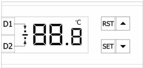
text_image
D1 D2 88.8 °C RST ▲ SET ▼D1, D2: Indicators of thermostat working state
| D1 | ON: Thermostat works in intelligent control modeOFF: Thermostat works in constant temperature control modeFLASHES: Thermostat is working in parameter setting mode or displaying room temperature |
| D2 | ON: Chiller works in refridge rating stateOFF: Chiller works in the insulation working stateFLASHES: Chiller works in energy-saving state |
(1) Press ▲ to show the room temperature. Holding the button for 6 seconds to display the restore defaults
(2) ▲▼ keys are for adjusting the controller parameters
(3) RST: Enter button
(4) SET: Function setting key
Parameters Adjustment - Settings
Restore to factory settings
Before machine startup, press and keep holding ▲▼ buttons while turning the chiller on. Release the buttons when the controller displays „rE“. After 6 seconds the device works in normal order with parameter settings restored to factory settings.
General settings
Press SET to enter the user-defined state. (Meanwhile, D1 flashes to indicate the controller is in parameters setup status)
(1) Under intelligent mode, the control panel displays the temperature difference value between water and air (F1)
(2) Under constant temperature mode, the control panel displays the set temperature value (F0)
Change settings with ▲▼ and press enter (RST) to save and exit. The new parameters take effect now. Or press SET to exit without saving parameters.
If there is no more action within 20 seconds, the controller will automatically exit modifying status without saving.
Advanced settings
(1) Press and hold ▲ + SET for 5 seconds until „0“ is displayed. Then press ▲ to select the password which has been set before (factory setting is 8). Press SET, if the password is correct, „F0“ is shown and you're entering set status. (D1 fl ashes to indicate the controller is in parameters setup status). If you choose the wrong password the panel returns to temperature display.
(2) In setup state press ▲ or ▼ to switch between functions and select with SET. After selecting an option, the original settings are displayed. Modify them with ▲▼. Press SET to save and return to previous setup menu. Press RST to save and return to temperature display. If no button is pressed within 20 seconds, the controller will automatically exit modifying status without saving.
Note:
(1) parameters setting condition: System still runs under original parameters
(2) constant temperature control mode: Water temperature is controlled by F0 parameters
(3) intelligent control mode: Water temperature depends on room temperature and parameters
Parameter List
Settings Overview
| Order | Displayed Code | Item | Range Factory settings | Note | |
| 1 | F0 Temperature setting | F9 ~ F8 | 25 | affects temperature in constant control mode | |
| 2 | F1 | Temperature diffence value | -15 ~ +5 | -2 | affects temperature in intelligent control mode |
| 3 | F2 | Cooling hysteresis | 0.1 ~ 3.0 | 0.8 | |
| 4 | F3 | Control mode | 0 ~ 1 | 1 | 1: intelligent0: constant |
| 5 | F4 | Alarm for too highwater temperature | 1 ~ 20 | 10 | |
| 6 | F5 | Alarm for too low water temperature | 1 ~ 20 | 15 | |
| 7 | F6 | Alarm for too high room temperature | 40 ~ 20 | 45 | |
| 8 | F7 | Password | 00 ~ 99 | 8 | |
| 9 | F8 | highest allowed water temperature | F0 ~ 40 | 30 | |
| 10 | F9 | lowest allowed water temperature | 1 ~ F9 | 20 | |
Settings - example of use
Switch to constant temperature mode
(1) Hold down ▲ + SET for 5 seconds, until it shows "0". Set the value with ▲ and select the password you have set (Factory default is 8). Press SET; if the password is correct the display will show „F0“ and you will be in the settings menu. (Display D1 will blink to show parameter mode) If the password is incorrect, you will be returned to the temperature display.
(2) In the settings menu, press ▲ to reach menu point "F3". Press SET to apply settings. The display will read "1"(Intelligent mode). With ▼, change the value to "0" (constant temperature mode).
(3) Confirm your selection with SET to save your selection and return to the settings menu
Or
Use RST to save your settings and return to the home screen.
If you do not press any keys within 20 seconds, you will automatically leave settings mode without saving.
Set water temperature - in constant temperature mode
(1) The heat exchanger is running in constant temperature mode.
(2) Press SET; the display will now read "F3". Change the value with ▼ to "F0" and confirm your selection with SET.
(3) The set temperature value will be displayed. Using ▲▼, set this value to your liking.
(4) Confirm your selection with SET to save your selection and return to the settings menu.
Or
Use RST to save your settings and return to the home screen.
If you do not press any keys within 20 seconds, you will automatically leave settings mode without saving.
Flow Alarm
In order to guarantee the equipment will not be damaged while cooling water circulation is out of control, the chiller has a low-flow alarm security feature. The flow alarm is connected to the normally open and normally closed relay contacts, requiring operating current less than 5 A, working voltage less than 300 V.
Wiring diagram - output ports
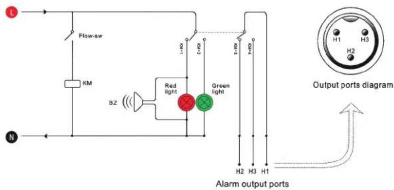
text_image
L Flow-sw KM BZ Red light Green light S-HP S-HP H-HP H2 H3 H1 Output ports diagram N Alarm output portsFlow alarm causes
| Condition\Display | NORMAL LED | ALARM LED Buzzer | OUT H1, H2 | OUT H1, H3 | ||
| pump works properly | ON | OFF OFF | no sound | ON | ||
| Blocked water circulation loop | OFF | ON | sounds | ON | OFF | |
| Water shortage alarm | OFF | ON | sounds | ON | OFF | |
| Faulted pump | OFF | ON | sounds | ON | OFF | |
| Power interruption | ON | OFF | ||||
Alarm - Fault Indication
Error messages
| Display | E1 | E2 | E3 E4 | E5 | |
| Meaning | room temperature too high | water temperature too high | water temperature too low | Room temperature sensor failure | Water temperature sensor failure |
When alarm occurs, the error code will be displayed.
The alarm sound will be suspended by pressing any button, but the alarm code remains on display until the alarming condition is eliminated.
Troubleshooting
| Failure Fault Cause Approach | ||
| Machine turned on but not receiving power Power cord is not plugged in place | Check and ensure the power interface and the power plug is plugged in place and in good contact. | |
| Fuse burnt-out | Pull out the fuse box from the power supply interface of the chiller, check the fuse, replace with spare fuse, if necessary and check whether the power supply voltage is stable. Check and ensure the power interface and the power plug is plugged in place and in good contact. | |
| Flow Alarm (red LED on) - no water flow despite everything being connected properly | Water level is too low | Check the water level gauge, add water until the level is in the green area. Also check whether water circulation tube leaks |
| Water circulation tubes are blocked or tubes are deformed by bending | Check water circulation tubes. They should not be bent or twisted. | |
Alarm - Fault Indication
| Failure Fault Cause | Approach | |
| Ultra-high temperature alarm Blocked dust gauze, bad thermolysis | Unpick and wash the dust gauze regularly. | |
| Poor ventilation for air outlet and inlet | Ensure a smooth ventilation for air outlet and inlet. | |
| Voltage is extremely low or unstable | Improve the power supply circuit or use a voltage regulator. | |
| Improper parameter settings on thermostat | Reset controlling parameters or restore factory settings. | |
| Power is switched on frequently | Ensure there is suffi cient time for refrigeration (more than 5 minutes). | |
| Excessive heat load | Reduce the heat load or use other model with larger cooling capacity. | |
| Alarm for ultra-high room temperature | The working ambient temperature is too high for the chiller | Improve the ventilation to guarantee the machine is running under 40°C. |
| Serious problems with condensate water | Water temperature is much lower than ambient temperature, with high humidity | Increase water temperature or preserve heat for pipeline. |
| Water drains slowly from drain during water changing | Fillport is not open | Open the Fillport. |
Technical Specification
| Model Chiller 2000 | |
| Voltage 220V | |
| Frequency 50 Hz | |
| Current 2.4 ~ 3.3 A | |
| Compressor Power 0.49 / 0.57 KW (0.66 / 0.77 HP) | |
| Refrigeration Capacity 1.41 / 1.70 KW | |
| Refrigerant R-134a | |
| Refrigerant Charge 380 g | |
| Noise level 65 db(A) | |
| Precision ± 0.3 °C | |
| Reducer Capillary | |
| Protection Over current protection for compressor, flow alarm, over temperature alarm | |
| Pump Power | 0.03 KW |
| Reservoir Capacity | 9 L |
| Inlet / Outlet | G I/4 Inner threads |
| max. Lift | 10 m |
| max. Flow | 10 L/min |
| Netto Gewicht | 29 kg |
| Dimension | 56 x 28 x 47 cm (L x W x H) |

Deutsch
Inhaltsverzeichnis
Englische Anleitung
Deutsche Anleitung
natural_image
Line drawing of a kitchen appliance with a lid and ventilation grilles (no text or symbols)natural_image
Technical line drawing of a mechanical assembly with gears and shafts (no text or symbols)natural_image
Line drawing of a server unit with fan and power connector (no text or symbols)text_image
FULL FULL NORMAL NORMAL ALARM ALARM4
text_image
L Flow-sw KM BZ Red light Green light L-HX L-HY L-C-X H-HX H2 H3 H1 Output ports diagram N Alarm output portsConf i guration 36-39
Alerte de débit 40
natural_image
Line drawing of a kitchen appliance with a lid and ventilation grilles (no text or symbols)1
natural_image
Technical line drawing of a mechanical assembly with gears and shafts (no text or symbols)2
natural_image
Line drawing of a power outlet with fan and plug, no text or symbols present3
text_image
FULL FULL NORMAL NORMAL ALARM ALARM4
Vérifi er niveau de liquide
General Manager: Fabian Noelte