MS55800E - Snow blower NAC - Free user manual and instructions
Find the device manual for free MS55800E NAC in PDF.


| Product type | Snow blower |
| Brand | NAC |
| Model | MS55800E |
| Cleaning width | 55.9 cm (22 in) |
| Intake height | 32.0 cm (12.6 in) |
| Engine | Briggs & Stratton, 4-stroke, 205 cm³ |
| Power rating | 8.00 HP at 3060 RPM |
| Starting | Electric 230V and manual |
| Engine oil capacity | 0.54 to 0.59 L (18-20 oz) |
| Recommended oil type | Synthetic 5W30 |
| Fuel tank capacity | 2.8 L (3 pints) |
| Wheel width | 20.3 x 5.01 cm (8.0 x 2.0 in) |
| Chute rotation | Manual, 200° |
| Chute deflector | Manual (quick adjust depending on model) |
| Drive | Auger propelled |
| Spark plug | Long-life platinum (gap 0.76 mm) |
| Weight | Approximately 45 kg (estimate) |
| Maintenance | Oil change every 50 h, spark plug/year |
| Safety | Engine stop + remove key before maintenance |
| Spare parts | Available from authorized dealer |
Frequently Asked Questions - MS55800E NAC
User questions about MS55800E NAC
0 question about this device. Answer the ones you know or ask your own.
Ask a new question about this device
Download the instructions for your Snow blower in PDF format for free! Find your manual MS55800E - NAC and take your electronic device back in hand. On this page are published all the documents necessary for the use of your device. MS55800E by NAC.
USER MANUAL MS55800E NAC
natural_image
Line drawing of a lawn mower with open lid and mechanical components (no text or symbols)Single Stage Snowthrower
Model No. Description
1695886 Single Stage Snowthrower, 8.00 TP / 22 Inch
C
B
A
A
D
G
F
E
A
B
C
A
en
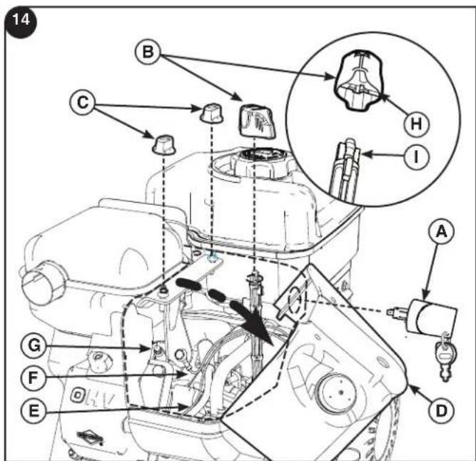
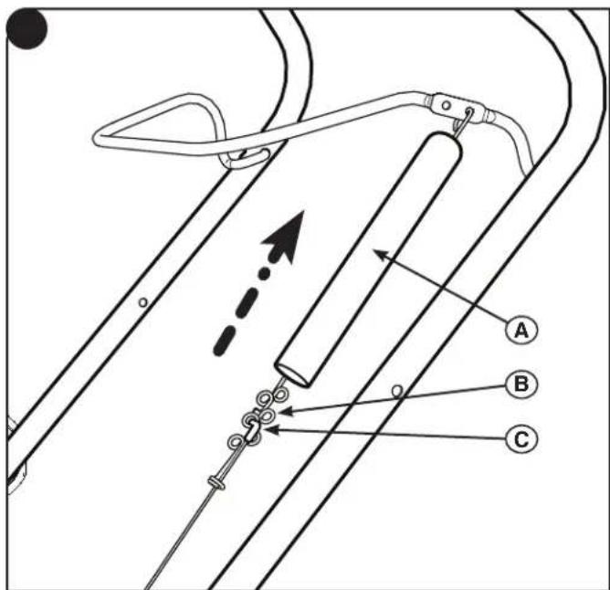
Table of Contents
| Illustrations | 2 |
| Operator Safety | 6 |
| Features and Controls | 12 |
| Operation | 13 |
| Maintenance | 17 |
| Storage | 19 |
| Troubleshooting | 20 |
| Specifications | 21 |
NOTE: In these instructions, "left" and "right" are referenced from the operating position.
General Information
Thank you for purchasing this quality-built MURRAY snowthrower. We're pleased that you've placed your confidence in our brand. When operated and maintained according to the instructions in this manual, your MURRAY product will provide many years of dependable service.
This manual contains safety information to make you aware of the hazards and risks associated with snowthrowers and how to avoid them. This snowthrower is designed and intended only for snow removal and is not intended for any other purpose. It is important that you read and understand these instructions thoroughly before attempting to start or operate this equipment. Save these instructions for future reference.
CE Identifi cation Tag
| A | |||
| Part No. xxxxxxxx | |||
| B | xxxxxxxxxxxxxxxxxx Serial No. xxxxxxxxxxxxx | XXXdB | I |
| E | xxxxxxxxxxxxxxxxxxxxxxxxxxxxxxxxxxxxxxxxxxxxxxxxxxxxxxxxxxxxxxxxxxxxxxxxxxxxxxxxxxxxxxxxxxxxxxxxxxxxxxxxxxxxxxxxxxxxxxxxxxxxxxxxxxxxxxxxxxxxxxxxxxxxxxxxxxxxxxxxxxxxxxxxxxxxxxxxxxxxxxxxxxxxxxxxxxxxxxxxxxxxxxxxxxxxxxxxxxxxxxxxxxxxxxxxxxxxxxxxxxxxxxxxxxxxxxxxxxxxxxxxxxxxxxxxxxxxxxxxxxxxxxxxxxxxxxxxxxxxxxxxxxxxxxxxxxxxxxxxxxxxxxxxxxxxxxxxxxxxxxxxxxxxxxxxxxxxxxxxxxxxxxxxxxxxxxxxxxxxxxxxxxxxxxxxxxxxxxxxxxxxxxxxxxxxxxxxxxxxxxxxxxxxxxxxxxxxxxxxxxxxxxxxxxxxxxxxxxxxxxxxxxxxxxxxxxxxxxxxxxxxxxxxxxxxxxxxxxxxxxxxxxxxxxxxxxxxxxxxxxxxxxxxxxxxxxxxxxxxxxxxxxxxxxxxxxxxxxxxxxxxxxxxxxxxxxxxxxxxxxxxxxxxxxxxxxxxxxxxxxxxxxxxxxxxxxxxxxxxxxxxxxxxxxxxxxxxxxxxxxxxxxxxxxxxxxxxxxxxxxxxxxxxxxxxxxxxxxxxxxxxxxxxxxxxxxxxxxxxxxxxxxxxxxxxxxxxxxxxxxxxxxxxxxxxxxxxxxxxxxxxxxxxxxxxxxxxxxxxxxxxxxxxxxxxxxxxxxxxxxxxxxxxxxxxxxxxxxxxxxxxxxx | kg: xxx kW: x.xx 20xx xxxx max | H C |
| F G D | |||
A. Manufacturer's Identification Number
B. Manufacturer's Serial Number
C. Power Rating in Kilowatts
D. Maximum Engine Speed in Rotations per Minute
E. Manufacturer's Name and Address
F. Year of Manufacture
G. CE Compliance Logo
H. Mass of Unit in Kilograms
I. Guaranteed Sound Power in Decibels
Product Reference Data
When contacting your authorized dealer for replacement parts, service, or information you MUST have these numbers.
Record your model name/number, manufacturer's identification numbers, and engine serial numbers in the space provided for easy access.
E DATA
Model Description Name/Number
Unit SERIAL Number
Dealer Name
Date Purchased
ENGINE Reference Data
| Engine Make | Engine Model |
| Engine Type/Spec | Engine Code/Serial Number |
The Illustrated Parts List for this machine can be downloaded from www.murray.com. Please provide model and serial number when ordering replacement parts.
Copyright © 2010 Briggs & Stratton Power Products Group, LLC
Milwaukee, WI, All rights reserved.
MURRAY is a trademark of Briggs & Stratton Power Products Group, LLC Milwaukee, WI USA
Operator Safety
Hazard Symbols and Meanings Control Symbols on Equipment
Read the Operator's Manual for operating and safety instructions
On / Off Key Switch
Shutoff engine and remove key before performing maintenance and repair work
Turn Choke Closed to Start
Thrown Objects Hazard
Turn Choke Open to Run
Fire Hazard
Push Primer 2 Times
Rotating Auger / Amputation Hazard
Plug in Extension Cord
Carbon Monoxide Poisoning Hazard
Push Button to Start
Keep safe distance
Engage Auger
Electric Shock
Chute Rotation
Rotating Impeller / Amputation Hazard
Cold Engine
Keep Children Away
Hot Engine
Safety Alert Symbol and Signal Words
The safety alert symbol and signal word (DANGER, WARNING, CAUTION, or NOTICE) is used to indicate the likelihood and potential severity of personal injury and/or damage to the product. In addition, a hazard symbol may be used to represent the type of hazard.

DANGER indicates a hazard which, if not avoided, will result in death or serious injury.

RNING indicates a hazard which, if not avoided, could result in death or serious injury.

CAUTION indicates a hazard which, if not avoided, could result in minor or moderate injury.
NOTICE indicates a situation that could result in damage to the product.

WARNING
Certain components in this product and its related accessories contain chemicals known to the State of California to cause cancer, birth defects, or other reproductive harm. Wash hands after handling.

WARNING
The engine exhaust from this product contains chemicals known to the State of California to cause cancer, birth defects, or other reproductive harm.

WARNING
- Hand contact with the rotating impeller inside the discharge chute is the most common cause of injury associated with snowthrowers.
- This snowthrower is capable of amputating hands and feet, and throwing objects. Read and observe all the safety instructions in this manual. Failure to do so could result in death or serious injury.

WARNING

Read, understand, and follow all the instructions on the snowthrower and in the operator's manual before operating this unit. Failure to observe the safety instructions in this manual could result in death or serious injury.
- Be thoroughly familiar with the controls and the proper use of the snowthrower.
- Make sure you are properly trained before operating the snowthrower.
- Know how to stop the unit and disengage the controls quickly.
- Never allow anyone to operate the snowthrower without proper instruction.
- Always follow the instructions in the operator's manual, if the snowthrower will be stored for an extended period.
- Maintain or replace safety and instruction labels as necessary.
- Never attempt to make major repairs on the snowthrower unless you have been properly trained. Improper servicing of the snowthrower can result in hazardous operation, equipment damage, and voiding of the product warranty.

DANGER

Discharge chute contains rotating impeller to throw snow. Never clear or unclog the discharge chute with your hands. Fingers can quickly become caught in the impeller. Always use a clean-out tool.
Failure to observe these safety instructions will result in traumatic amputation or severe laceration.
| DANGER | |
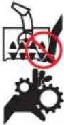 | Keep hands, feet, and clothing away from rotating parts. Rotating parts can contact or entangle hands, feet, hair, clothing, or accessories.Failure to observe these safety instructions will result in traumatic amputation or severe laceration. |
| · Whenever cleaning, repairing, or inspecting the snowthrower, make sure the engine is OFF, spark plug wire is disconnected, and all moving parts have stopped.· Do not put hands or feet near or under rotating parts. Keep clear of the discharge opening at all times.· Never operate the snowthrower without proper guards, and other safety devices in place and working.· Never leave the snowthrower unattended while engine is running. Always disengage the auger and traction controls, stop engine, and remove keys.· Keep all loose clothing away from the front of the snowthrower and auger. Scarves, mittens, dangling drawstrings, loose clothes, and pants can quickly become caught in the rotating device and amputation will occur. Tie up long hair and remove jewelry.· Run the machine a few minutes after discharging snow to prevent freeze-up of the collector/impeller.· Disengage power to the collector/impeller when snowthrower is transported or not in use. | |
| DANGER | |
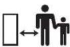 | Tragic accidents can occur if the operator is not alert to the presence of children. Children are often attracted to the unit and the operating activity. Never assume the children will remain where you last saw them. |
| Keep children out of the area during operation. Children are often attracted to the equipment. Be mindful of all persons present.Be alert and turn unit off if children enter the area.Never allow children to operate the unit.Use extra care when approaching blind corners, shrubs, trees, or other objects that may obscure vision. Children may be present. | |
| DANGER | |
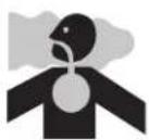 | Engines give off carbon monoxide, an odor-less, colorless, poison gas. Breathing carbon monoxide can cause nausea, fainting, or death. |
| Start and run engine outdoors.Do not run the engine in an enclosed area, even if doors or windows are open. | |
| DANGER | |
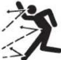 | Objects can be picked up by auger and thrown from chute. Never discharge snow toward bystanders or allow anyone in front of the snowthrower. Failure to observe these safety instructions will result in death or serious injury. |
| ·Always wear safety glasses or eye shields during operation, and while performing an adjustment or repair. ·Always be aware of the direction the snow is being thrown. Nearby pedestrians, pets, or property may be harmed by objects being thrown. ·Be aware of your environment while operating the snowthrower. Don't run over items such as gravel, doormats, newspapers, toys, and rocks hidden under snow, as they can all be thrown from the chute or jam in the auger. ·Use extreme caution when operating on or crossing gravel drives, walks, or roads. ·Adjust the collector housing height to clear gravel or crushed rock surface. ·Never operate the snowthrower near glass enclosures, automobiles, window wells, drop-offs, and the like without proper adjustment of the discharge chute angle. ·Familiarize yourself with the area in which you plan to operate the snowthrower. Mark off boundaries of walkways and driveways. | |
| WARNING | |
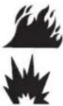 | Fuel and its vapors are extremely fl ammable and explosive. Always handle fuel with extreme care.Failure to observe these safety instructions can cause a fi re or explosion which will result in severe burns or death. |
| WHEN ADDING FUELTurn off engine and let cool at least 2 minutes before removing the fuel cap and adding fuel.Fill fuel tank outdoors or in a well ventilated area.Do not overfill the fuel tank. To allow for the expansion of gasoline, do not fill above the bottom of the fuel tank neck.Keep fuel away from sparks, open flames, pilot lights, heat, and other ignition sources.Check fuel lines, cap, and fittings frequently for cracks or leaks. Replace if necessary.Use an approved fuel container.If fuel spills, wait until it evaporates before starting engine.WHEN STARTING ENGINEEnsure that spark plug, muffler, fuel cap, and air cleaner (if equipped) are in place and secured.Do not crank the engine with the spark plug removed.If fuel is spilled, do not attempt to start the engine, but move the snowthrower away from the area of the spill, and avoid creating any source of ignition, until the fuel vapors have dissipated.Do not over-prime the engine. Follow the engine starting instructions in this manual.If the engine floods, set choke (if equipped) to OPEN/RUN position, move throttle (if equipped) to FAST position and crank until engine starts.WHEN OPERATING EQUIPMENTDo not tip the snowthrower at an angle which causes the fuel to spill.Do not choke the carburetor to stop the engine.Never run the engine with the air cleaner assembly (if equipped) or the air filter (if equipped) removed.WHEN CHANGING OILIf you drain the oil from the top oil fill tube, the fuel tank must be empty or fuel can leak out and result in a fire or explosion.WHEN TRANSPORTING EQUIPMENTTransport with fuel tank EMPTY, or with fuel shut-off valve OFF.WHEN STORING GASOLINE OR EQUIPMENT WITH FUEL IN TANKStore away from furnaces, stoves, water heaters, or other appliances that have pilot light or other ignition source because they can ignite fuel vapors. | |
| WARNING | |
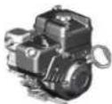 | Safe operation of the snowthrower requires the proper care and maintenance of the engine. |
| • Disengage all clutches and shift into neutral before starting the engine may cause personal injury.• Let the engine adjust to outdoor temperatures before starting to clear snow.• Use a grounded three-wire plug for all snowthrowers equipped with electric drive motors or electric starting motors. | |
| WARNING | |
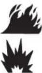 | Starting engine creates sparking.Sparking can ignite nearby fl ammable gases.Explosion and fi re could result. |
| ·If there is natural or LP gas leakage in area, do not start engine.·Do not use pressurized starting fluids because vapors are flammable. | |
| WARNING | |
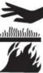 | Running the engine produces heat. Engine parts, especially muffler, become extremely hot.Failure to observe these safety instructions could result in severe thermal burns on contact. |
| Never touch a hot engine or muffler. Allow muffler, engine cylinder, and fins to cool before touching.Remove debris from muffler area and cylinder area.Install and maintain in working order a spark arrester before using equipment on forest-covered, grass-covered, or brush-covered unimproved land.It is a violation of California Public Resource Code, Section 4442, to use or operate the engine on any forest-covered, brush-covered, or grass-covered land unless the exhaust system is equipped with a spark arrester, as defined in Section 4442, maintained in effective working order. Other states or federal jurisdictions may have similar laws. Contact the original equipment manufacturer, retailer, or dealer to obtain a spark arrester designed for the exhaust system installed on this engine. | |
 | This snowthrower must be properly maintained to ensure safe operation and performance.Failure to observe the safety instructions in this manual could result in death or serious injury. |
| When performing any maintenance or repairs on the snowthrower, shut OFF the engine, disconnect spark plug wire, and keep the wire away from the plug to prevent someone from accidentally starting the engine.Check shear bolts and other hardware at frequent intervals for proper tightness.Keep nuts and bolts tight and keep snowthrower in good condition.Never tamper with safety devices. Check their proper operation regularly and make necessary repairs if they are not functioning properly.Components are subject to wear, damage, and deterioration. Frequently check components and replace with recommended parts, when necessary.Check control operation frequently. Adjust and service as required.Use only factory authorized replacement parts, or like, parts when making repairs.Always comply with factory specifications on all settings and adjustments.Use only factory authorized, or like, attachments and accessories such as wheel weights, counterweights, or cabs.Never attempt to make any adjustments while the engine is running (except when specifically recommended by the factory). | |
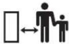
- Keep the area of operation clear of all persons, particularly small children and pets.
- Thoroughly inspect the area where the snowthrower will be used and remove all doormats, sleds, boards, wires, and other foreign objects.
- Do not operate the snowthrower without wearing adequate winter clothing.
- Wear footwear that will improve footing on slippery surfaces.
- Use caution to avoid slipping or falling especially when operating the snowthrower in reverse.
- Never operate the snowthrower without good visibility or light. Always be sure of your footing, and keep a firm hold on the handles.
- Do not clear snow across the face of slopes. Use extreme caution when changing direction on slopes. Do not attempt to clear steep slopes.
- Do not overload the machine capacity by attempting to clear snow too quickly.
- Never operate the snowthrower at high transport speeds on slippery surfaces. Look behind the snowthrower and use care when operating in reverse.
- Do not use the snowthrower on surfaces above ground level such as roofs of residences, garages, porches, or other such structures or buildings.
- Operators should evaluate their ability to operate the snowthrower safely enough to protect themselves and others from injury.
- The snowthrower is intended to remove snow only. Do not use the snowthrower for any other purpose.
- Do not carry passengers.
- After striking a foreign object, shut OFF the engine, disconnect the cord on electric motors, thoroughly inspect the snowthrower for any damage, and repair the damage before restarting and operating the snowthrower.
- If the snowthrower vibrates abnormally, shut OFF the engine. Vibration is generally a warning of trouble. See an authorized dealer if necessary for repairs.
- For models equipped with electric starting motors, disconnect the power cord after the engine starts.
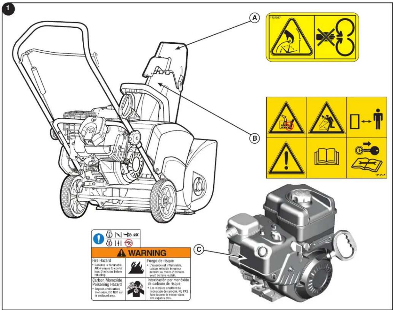
Before operating your snowthrower, read the safety decals installed on your snowthrower. The cautions and warnings are for your safety. To avoid a personal injury or damage to your snowthrower, understand and follow all the safety decals.
If any safety decals become worn or damaged and cannot be read, order replacement decals from your local dealer.
A — Part No. 1727207 Chute Danger Decal
B — Part No. 1739967 Auger Danger Decal
C — Part No. 279655 Choke / Control Warning Decal
en
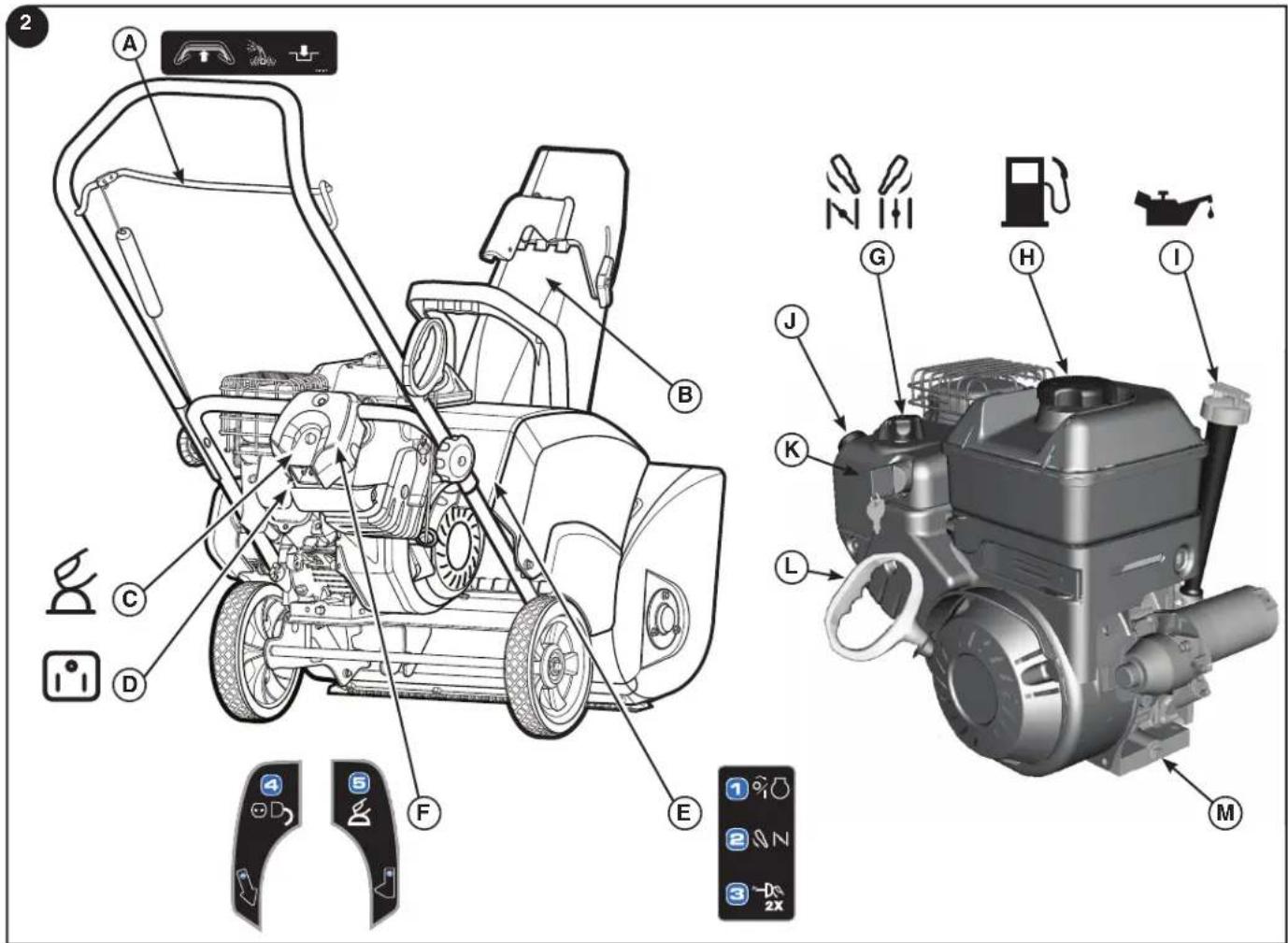
Snowthrower Controls and Operation Decals (Figure 2)
A — Auger Control
B — Deflector Control Lever
C — Electric Start Button
D — Power Cord Receptacle
E — Starting Instructions / Steps 1-3
F — Starting Instructions / Step 4 & 5
Engine Controls
G — Choke Control Knob
H — Fuel Tank and Cap
I — Oil Fill Cap (Extended Dipstick)
J — Primer Button
K — ON/OFF or Push/Pull Key (As equipped)
L — Starter Cord Handle
M—Oil Drain
WARNING
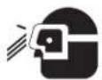
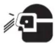
The operation of any snowthrower can result in foreign objects being thrown into the eyes, which can result in severe eye damage. Always wear safety glasses or eye shields before beginning snowthrower operation.
Check / Add Oil
NOTICE: The engine was shipped from the factory without oil. Before you start the engine, make sure you add oil according to the instructions in this manual. If you start the engine without oil, it will be damaged beyond repair and will not be covered under the warranty.
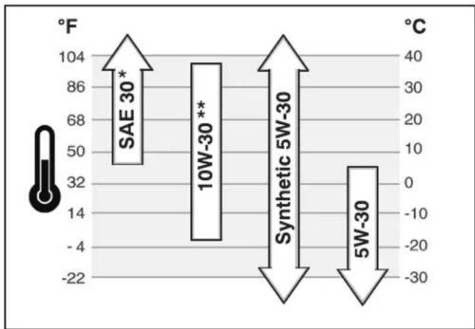
- Make sure the unit is level. Use a high quality detergent oil classified "For Service SG, SH, SJ, SL, or higher". Synthetic 5W30 motor oil is acceptable for all temperatures. DO NOT mix oil with gasoline. See Chart for oil recommendations.
- Remove the oil fill cap/dipstick (A, Figure 3) and wipe with a clean cloth.
- Insert the cap/dipstick and turn clockwise to tighten.
- Remove the oil fill cap/dipstick and check the oil.
- If necessary, add oil until the level reaches the FULL mark on the oil fill cap/dipstick. Do not overfill.
- Tighten the cap/dipstick securely.
bar
| Category | Value | |---|---| | SAE 30* | 104 | | 10W-30** | 68 | | Synthetic 5W-30 | -4 | | 5W-30 | -22 |* Below 40°F (4°C) the use of SAE 30 will result in hard starting.
** Above 80°F (27°C) the use of 10W-30 may cause increased oil consumption. Check oil level more frequently.
Fuel Recommendations
Fuel must meet these requirements:
- Clean, fresh, unleaded gasoline.
- A minimum of 87 octane/87 AKI (91 RON). High altitude use, see below.
• Gasoline with up to 10% ethanol (gasohol) or up to 15% MTBE (methyl tertiary butyl ether) is acceptable.
NOTICE: Do not use unapproved gasoline, such as E85. Do not mix oil in gasoline or modify the engine to run on alternate fuels. This will damage the engine components and void the engine warranty.
To protect the fuel system from gum formation, mix a fuel stabilizer into the fuel. All fuel is not the same. If starting or performance problems occur, change fuel providers or change brands. This engine is certified to operate on gasoline. The emissions control system for this engine is EM (Engine Modifications).
High Altitude
At altitudes over 5,000 feet (1524 meters), a minimum 85 octane/85 AKI (89 RON) gasoline is acceptable. To remain emissions compliant, high altitude adjustment is required. Operation without this adjustment will cause decreased performance, increased fuel consumption, and increased emissions. See a Briggs & Stratton Authorized Dealer for high altitude adjustment information.
Operation of the engine at altitudes below 2,500 feet (762 meters) with the high altitude kit is not recommended.
Add Fuel
| WARNING | |
 | Fuel and its vapors are extremely fl ammable and explosive.Fire or explosion can cause severe burns or death. |
| When Adding FuelTurn engine off and let engine cool at least 3 minutes before removing the fuel cap.Fill fuel tank outdoors or in well-ventilated area.Do not overfill fuel tank. To allow for expansion of the fuel, do not fill above the bottom of the fuel tank neck.Keep fuel away from sparks, open flames, pilot lights, heat, and other ignition sources.Check fuel lines, tank, cap, and fittings frequently for cracks or leaks. Replace if necessary.If fuel spills, wait until it evaporates before starting engine. | |
- Clean the fuel cap area of dirt and debris. Remove the fuel cap (A, Figure 4).
- Fill the fuel tank with fuel. To allow for expansion of the fuel, do not fill above the bottom of the fuel tank neck.
- Reinstall the fuel cap.
Start the Engine
 WARNING WARNING | |
 | The electric starter is equipped with a three-wire power cord and plug designed to operate on AC household current. The power cord must be properly grounded at all times to avoid the possibility of electric shock. |
| If your house does not have a three-wire grounded system, do not use this electric starter. Contact a licensed electrician for installation of a three-wire grounded system. | |
| (8527) WARNING |
| Always connect the power cord fi rst to the switch box located on the equipment and then plug the other end into a grounded receptacle. After starting, disconnect the power cord from the grounded receptacle fi rst. |
Be sure that engine oil is at FULL mark on the oil fill cap/dipstick. The snowthrower engine is equipped with an AC electric starter and recoil starter. Before starting the engine, be certain that you have read the following information.
If engine floods, set the choke to the OPEN/RUN position and crank until the engine starts.
Start the engine as follows:
- Check the oil level. See the Check/Add Oil section.
- Make sure auger control is disengaged.
- Insert the ON/OFF key (A, Figure 5) and turn to the ON position or insert the Push/Pull key, if equipped.
-
Turn the choke knob (B) fully clockwise if engine is cold.
NOTE: Do not use the choke to start a warm engine. -
Push the primer button (C) two times.
NOTE: Do not use the primer to start a warm engine.
| WARNING | |
 | Rapid retraction of the starter cord (kickback) will pull your hand and arm toward the engine faster than you can let go. |
| Broken bones, fractures, bruises, or sprains could result.When starting engine, pull the starter cord slowly until resistance is felt and then pull rapidly to avoid kickback. | |
- Rewind Start: Firmly hold the starter cord handle (D, Figure 5). Pull the starter cord handle slowly until resistance is felt, then pull rapidly.
NOTE: If the engine does not start after three attempts, see the Troubleshooting section in the Engine Manual.
| WARNING | |
 | If the extension cord is damaged, it must be replaced by the manufacturer (or its service agent) or a similarly qualified person to avoid a hazard. |
-
Electric Start: First connect the extension cord (E, Figure 6) to the power cord receptacle (F) and then into a wall receptacle. If additional extension cord is required, make sure it is three-wire.
-
Electric Start: Depress the starter push button (G). After you start the engine, first disconnect the extension cord from the wall receptacle and then from the power cord receptacle.
Important: To extend the life of the starter, use short starting cycles (five seconds maximum). Wait one minute between starting cycles.
NOTE: If the engine does not start after three attempts, see the Troubleshooting section in the Engine Manual.
Stop the Engine
| WARNING | |
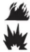 | Gasoline and vapors are extremely fl ammable and explosive. Fire or explosion can cause severe burns or death. DO NOT choke the carburetor to stop the engine. |
Before stopping the engine, allow it to idle for a few minutes to help dry off any moisture.
- Turn the ON/OFF or Push/Pull key (A, Figure 7) to the OFF position and remove or pullout the Push/Pull key if equipped.
- Keep the ON/OFF or Push/Pull key out of the reach of children. The engine cannot be started without the ON/OFF or Push/Pull key.
Operate the Snowthrower
| WARNING | |
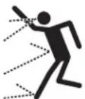 | Before operating, make sure the area in front of the snowthrower is clear of bystanders or obstacles. |
DO NOT discharge snow toward a building as hidden objects could be thrown with sufficient force to cause damage.
- Start the engine. See Start the Engine in this section.
- Adjust the direction and angle of the discharge chute (A, Figure 8). See Discharge Chute and Deflector in this section
- Fully press and hold the auger control (B) to engage the auger rotation. Releasing the auger control lever will disengage the auger.
- Push the unit into the snow.
Note: When clearing wet, heavy, snow, reduced your speed, maintain full throttle, and clear less than the full width of the unit.
- Tip the handle bars (C) forward slightly. This will cause the snowthrower to pull itself forward.
Stop the Snowthrower
| WARNING |
 |
| Read Operator's Manual before operating machine. This machine can be dangerous if used carelessly.Never operate the snowthrower without all guards, covers, and shields in place.Never direct discharge towards windows or allow bystanders near machine while engine is running.Stop the engine whenever leaving the operating position.Disconnect spark plug before unclogging the impeller housing or the discharge chute and before making repairs or adjustments.When leaving the machine, remove the safety key. To reduce the risk of fire, keep the machine clean and free from spilled gas, oil, and debris. |
| WARNING | |
 | Never run engine indoors or in an enclosed,poorly ventilated area. Engine exhaust containsCARBON MONOXIDE, an ODORLESS andDEADLY GAS. |
| Keep hands, feet, hair, and loose clothing away from anymoving parts on engine and snowthrower.Temperature of muffler and nearby areas can exceed 150°F(66°C). Avoid these areas.DO NOT allow children to operate or be near snowthrowerwhile it is operating. | |
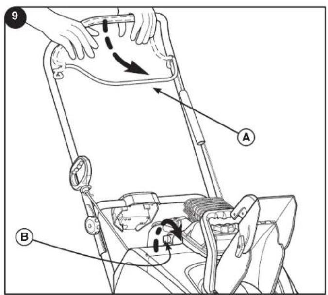
- Release the auger control (A, Figure 9).
- Turn the ON/OFF switch (B) to the OFF position and remove or pull out PUSH/PULL key.
en
Snowthrower Safety Test
| (DHZ7) WARNING | |
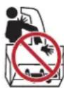 | Never run engine indoors or in an enclosed,poorly ventilated area. The discharge chutecontains a rotating auger to throw snow. Neverclear or unclog the discharge chute with yourhands. |
| Fingers can quickly become caught and traumatic amputationor severe laceration will result. Always use a clean-out tool toclear or unclog the discharge chute. | |
WARNING
| WARNING | |
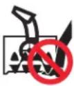 | Hand contact with the rotating auger inside the discharge chute is the most common cause of injury associated with snowthrowers. |
| This snowthrower is capable of amputating hands and feet, and throwing objects. Read and observe all the safety instructions in this manual. Failure to do so will result in death or serious injury. | |
Test - Auger/Impeller
- Start unit and engage auger control (A, Figure 9).
- Release auger control.
- Auger must stop in 5 seconds or less.
Discharge Chute and Defl ector
Manual Chute Rotation
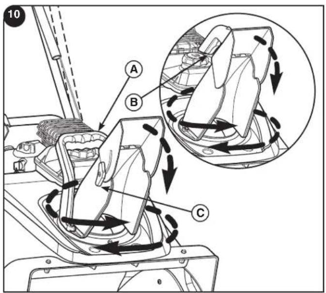
Grasp the chute handle (A, Figure 10) on the deflector and rotate the discharge chute to the left, right or forward position. A tension plate holds the chute in the desired position.
Note DO NOT use the chute handle to lift the unit.
Remote Chute Rotation (if equipped)
- Squeeze and hold the button (B, Figure 10, inset) on handle of remote chute control.
- Push the handle forward to rotate the chute counterclockwise or pull the handle backwards to rotate the chute clockwise as shown on Figure 10.
- Release the button to hold the desired chute location.
Note: Do not use excessive force when trying to operate frozen controls. Clean off any snow and ice from the base of the chute.
Manual Deflector Adjustment
Loosen the deflector wing knob (C, Figure 10) and adjust the deflector up or down to control the snow discharge height and distance. Tighten the wing knob securely to hold the desired deflector adjustment.
Quick Deflector Adjustment (if equipped)
Squeeze the trigger (B, Figure 10, inset). in the deflector handle and adjust the deflector up or down to control the snow discharge height and distance. Release the trigger to hold the desired deflector adjustment.
Clear a Clogged Discharge Chute
| WARNING | |
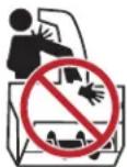 | Hand contact with the rotating impeller inside the discharge chute is the most common cause of injury associated with snowthrowers. Never clear or unclog discharge chute with your hands, or while engine is running. |
| Fingers can quickly become caught and traumatic amputation or severe laceration can result. | |
- SHUT OFF THE ENGINE!
- Wait 10 seconds to be sure that the impeller blades have stopped rotating.
- Use a clean-out tool to remove snow from the auger housing.
Operating Tips
- Most efficient snow removal is accomplished when snow is removed immediately after it falls.
- For complete snow removal, slightly overlap each swath previously taken.
- Snow should be discharged downwind whenever possible.
- On gravel or crushed rock surfaces, push down slightly on the handle bars to avoid ingesting rocks. DO NOT allow rocks and gravel to be picked up and thrown from snowthrower.
- After the snow removal has been completed, allow the engine to run for a few minutes, to melt accumulated snow and ice.
- Clean the snowthrower thoroughly after each use.
- Before starting snowthrower, always inspect auger for ice accumulation and/or debris, which could result in snowthrower damage.
- Check oil level before every start. Make sure the oil is at the FULL mark on the oil fill cap/dipstick.
| Snowthrower |
| After Each Use |
| Remove accumulated snow and slush from the unit to prevent freezing of controls |
| Every 8 Hours or Daily |
| Perform impeller safety tests |
| Every 25 Hours or Annually |
| Check snowthrower for loose hardware |
| Adjust auger control cable if necessary |
| See Dealer Annually to |
| Ensure rubber auger wear is not aff ecting performance |
| Engine |
| First 5 Hours |
| Change oil |
| Every 8 Hours or Daily |
| Check engine oil level |
| Every 50 Hours or Annually |
| Change engine oil |
| Check muffler and muffler guard. |
| Annually |
| Replace spark plug |
| Check valve clearance * |
* Not required unless problems are noted with engine performance. See authorized dealer.
Emissions Control Statement
Maintenance, replacement, or repair of the emissions control devices and systems may be performed by any non-road engine repair establishment or individual. However, to obtain “no charge” emissions control service, the work must be performed by a factory authorized dealer. See the Emissions Warranty.
Change the Oil
Remove Oil
Used oil is a hazardous waste product and must be disposed of properly. Do not discard with household waste. Check with your local authorities, service center, or dealer for safe disposal / recycling facilities.
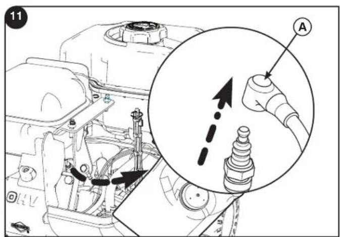
- With engine off but still warm, disconnect the spark plug wire (A, Figure 11) and keep it away from the spark plug.
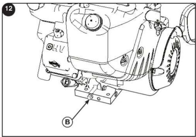
Note: To access the spark plug wire, you must first remove the snow hood from the engine. See Replace the Spark Plug in this section. - Tilt the unit back slightly, then remove the oil drain cap (B, Figure 12). Drain the oil into an approved receptacle.
- After the oil has drained, install and tighten the oil drain cap.
Add Oil
- Place engine level.
- Clean the oil fill area of any debris.
- See Specification section for oil capacity.
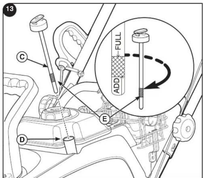
- Remove the dipstick (C, Figure13) and wipe with clean cloth.
- Pour the oil slowly into the engine oil fill (D). DO NOT overfill. Wait one minute and recheck the oil level.
- Install and tighten dipstick.
- Remove the dipstick and check the oil level. It should be at the top of the full indicator (E) on the dipstick.
- Install and tighten dipstick.
Access the Spark Plug
To access the spark plug, the snow hood must be removed as follows:
- Remove the ON/OFF key (A, Figure 14) or pull out the ON/OFF switch or Push/Pull key. Keep the key away from children.
- Grasp the choke control (B) and pull up to remove.
- Remove the mounting screws (C).
- Carefully remove the top part of the snow hood (D). DO NOT disconnect the primer hose (E) or the key wire (F).
- Remove the spark plug (G) and replace. (See Specifications).
- Before installation of the snow hood, make sure the primer hose and the key wire are connected.
- Mount the top of the snow hood to the snow hood base. Make sure the top interlocks with the base. Secure with mounting screws.
- Align the slots (H, Figure 14, Inset) in the choke knob with the tabs on the choke shaft (I) and push down to install. If knob is not installed correctly, the choke will not operate.
- DO NOT install the ON/OFF or Push/Pull key until you are ready to start the engine.
Auger Cable Adjustment
WARNING
Do not over-tighten, as this may lift the lever and cause the auger drive to be engaged without depressing the auger drive control.
WARNING
The auger must stop within 5 seconds after releasing the control. If it does not, see an authorized dealer.
If the auger no longer turns when the control is engaged, or if the belt slips under load, the auger cable or belt may have stretched. This can be compensated for by adjusting the auger cable. If the belt is too worn or broken, see your authorized dealer for repair.
Notice: The auger must not turn unless the auger control is engaged. The auger must disengage within 5 seconds after the auger control is released. If it does not, see your authorized dealer before further use.
Inspection
- Start the engine.
- Engage the auger control. The auger should turn.
- Release the auger control. The auger should stop within 5 seconds.
If the auger does not turn or stop as indicated above, perform the adjustment procedure, or take the unit to your local authorized dealer for repair.
Adjustment
- Turn off the engine and remove the key. Wait for all moving parts to stop.
- Slide the cable cover (A, Figure 15) up to expose the cable adjustment loops (B) and Z-bend (C).
- Disengage the cable Z-bend from the cable loops, and install it in the next highest loop to increase belt tension. Slide the cable boot back into place.
Note: There must be some slack in the cable when the control is released. - Keeping clear of the auger, reinsert the key, start the engine, and perform the Inspection procedure again. If the auger does not turn or stop as indicated, take the unit to your local authorized dealer for repair.
Storage
| WARNING | |
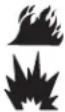 | Fuel and its vapors are extremely flammable and explosive.Fire or explosion can cause severe burns or death. |
| When Storing Fuel or Equipment with Fuel in Tank• Store away from furnaces, stoves, water heaters or other appliances that have pilot lights or ignition sources because they can ignite fuel vapors. | |
Fuel System
Fuel can become stale when stored over 30 days. Stale fuel causes acid and gum deposits to form in the fuel system or on essential carburetor parts. To keep fuel fresh, use Briggs & Stratton FRESH START® fuel stabilizer, available as a liquid additive or a drip concentrate cartridge.
There is no need to drain the gasoline from the engine if a fuel stabilizer is added according to the instructions. Run the engine for 2 minutes to circulate the stabilizer throughout the fuel system. The engine and fuel can be stored up to 24 months.
If gasoline in the engine has not been treated with a fuel stabilizer, it must be drained into an approved container. Run the engine until it stops from lack of fuel. The use of a fuel stabilizer in the storage container is recommended to maintain freshness.
Engine Oil
While the engine is still warm, change the engine oil.
Snowthrower
- Thoroughly clean the snowthrower.
- Lubricate all lubrication points (see authorized dealer).
- Make sure all nuts, bolts, and screws are securely fastened. Inspect all visible moving parts for damage, breakage, and wear. Replace if necessary.
- Touch up all rusted or chipped paint surfaces.
- Cover the bare metal parts of the auger and impeller with rust preventative.
- If possible, store your snowthrower indoors and cover it to protect from dust and dirt.
- On models with folding handles, loosen the knobs that secure the upper handle. Rotate the upper handle forward.
- If stored outdoors, place the snowthrower on blocks and ensure the entire machine is off the ground. Cover the snowthrower with a heavy tarpaulin.
Remove from Storage
- Raise the upper handle to the operating position and tighten the knobs that secure the upper handle.
- Fill the fuel tank with fresh fuel.
- Check the spark plug. Make sure the gap is correct. If the spark plug is worn or damaged, replace.
- Make sure all fasteners are tight.
- Make sure all guards, shields, and covers are in place.
| PROBLEM LOOK FOR REMEDY | ||
| Auger does not stop within 5 seconds after control lever is released. | Auger control cable out of adjustment | Adjust auger control cable. Refer to “Cable Adjustment” in the Maintenance section of this manual. If the auger does not stop within 5 seconds, see authorized dealer for repair. |
| Discharge chute or defl ector does not work (remote-manual). | Discharge chute or deflector needs lubrication. | See authorized dealer. |
| Discharge chute or deflector is frozen. | Put snowthrower in heated garage or let unit run for a few minutes or clean off any snow and ice from the base of the chute. | |
| Engine does not start. Key is off or not installed. Turn key in to the ON position. | ||
| Model No. | 1695886 | |
| ENGINE: | ||
| Brand Briggs & Stratton | ||
| Model Series | SnowTM | Series |
| Gross Torque* 8.00 T.P. @ 3060 rpm | ||
| Type | 4-Cycle | |
| Displacement 12.48 cu in. (205 cc) | ||
| Starting System Recoil, 230V Electric without Cord | ||
| Alternator | None | |
| Oil Capacity 18 - 20 oz (.54 - .59L) | ||
| Engine Oil | Synthetic | 5W30 |
| Fuel Tank Volume 3.0 qts (2.8 liters) | ||
| Spark Plug Gap and Torque 0.030 in. (0,76 mm) 180 lb-in (20 Nm) | ||
| Resistor Spark Plug | 491055 | |
| Long Life Platinum Spark Plug | 5066 | |
| Ignition System This spark plug ignition system complies with Canadian standard ICES-002. | ||
AUGER/IMPELLER:
| Clearing Width | 22 in. (55.9 cm) |
| Intake Height | 12.6 in. (32.0) cm) |
| Auger/Impeller Diameter | 10.0 in. (25.4 cm) |
| Number of Impeller Blades | 2 |
CHUTE:
| Chute Deflector | Quick Chute (Quick Deflector, if equipped) |
| Chute Rotation | Manual Rotation - 200° (Remote Rotation, if equipped) |
DRIVE SYSTEM:
| Drive Type | Auger - Propelled |
| Drive Speeds | N/A |
| Wheel Size | 8.0 x 2.0 in. (20.3cm x 50.1cm) |
\* Engine Power Rating Information
The gross power rating for individual gas engine models is labeled in accordance with SAE (Society of Automotive Engineers) code J1940 (Small Engine Power & Torque Rating Procedure), and rating performance has been obtained and corrected in accordance with SAE J1995 (Revision 2002-05). Torque values are derived at 3060 RPM; horsepower values are derived at 3600 RPM. Actual gross engine power will be lower and is affected by, among other things, ambient operating conditions and engine-to-engine variability. Given both the wide array of products on which engines are placed and the variety of environmental issues applicable to operating the equipment, the gas engine will not develop the rated gross power when used in a given piece of power equipment (actual “on-site” or net power). This difference is due to a variety of factors including, but not limited to, accessories (air cleaner, exhaust, charging, cooling, carburetor, fuel pump, etc.), application limitations, ambient operating conditions (temperature, humidity, altitude), and engine-to-engine variability. Due to manufacturing and capacity limitations, Briggs & Stratton may substitute an engine of higher rated power for this Series engine.
en
Table des matières
Illustrations....2
flowchart
graph TD
    A["Part No. xxxxxxxx"] --> B["XXXXXXXXXXXXXX"]
    B --> C["Serial No. xxxXXXXXXXXX"]
    C --> D["XXXXXXXXXXXXXX"]
    D --> E["XXXXXXXXXXXXXX"]
    E --> F["XXXXXXXXXXXXXX"]
    F --> G["XXXXXXXXXXXXXX"]
    G --> H["XXXXXXXXXXXXXX"]
    H --> I["XXXXXXXXXXXXXX"]
    I --> J["XXXXXXXXXXXXXX"]
    J --> K["XXXXXXXXXXXXXX"]
    K --> L["XXXXXXXXXXXXXX"]
    L --> M["XXXXXXXXXXXXXX"]
    M --> N["XXXXXXXXXXXXXX"]
    N --> O["XXXXXXXXXXXXXX"]
    O --> P["XXXXXXXXXXXXXX"]
    P --> Q["XXXXXXXXXXXXXX"]
    Q --> R["XXXXXXXXXXXXXX"]
    R --> S["XXXXXXXXXXXXXX"]
    S --> T["XXXXXXXXXXXXXX"]
    T --> U["XXXXXXXXXXXXXX"]
    U --> V["XXXXXXXXXXXXXX"]
    V --> W["XXXXXXXXXXXXXX"]
    W --> X["XXXXXXXXXXXXXX"]
    X --> Y["XXXXXXXXXXXXXX"]
    Y --> Z["XXXXXXXXXXXXXX"]
    Z --> AA["XXXXXXXXXXXXXX"]
    AA --> AB["XXXXXXXXXXXXXX"]
    AB --> AC["XXXXXXXXXXXXXX"]
    AC --> AD["XXXXXXXXXXXXXX"]
    AD --> AE["XXXXXXXXXXXXXX"]
    AE --> AF["XXXXXXXXXXXXXX"]
    AF --> AG["XXXXXXXXXXXXXX"]
    AG --> AH["XXXXXXXXXXXXXX"]
    AH --> AI["XXXXXXXXXXXXXX"]
    AI --> AJ["XXXXXXXXXXXXXX"]
    AJ --> AK["XXXXXXXXXXXXXX"]
    AK --> AL["XXXXXXXXXXXXXX"]
    AL --> AM["XXXXXXXXXXXXXX"]
    AM --> AN["XXXXXXXXXXXXXX"]
    AN --> AO["XXXXXXXXXXXXXX"]
    AO --> AP["XXXXXXXXXXXXXX"]
    AP --> AQ["XXXXXXXXXXXXXX"]
    AQ --> AR["XXXXXXXXXXXXXX"]
    AR --> AS["XXXXXXXXXXXXXX"]
    AS --> AT["XXXXXXXXXXXXXX"]
    AT --> AU["XXXXXXXXXXXXXX"]
    AU --> AV["XXXXXXXXXXXXXX"]
    AV --> AW["XXXXXXXXXXXXXX"]
    AW --> AX["XXXXXXXXXXXXXX"]
    AX --> AY["XXXXXXXXXXXXXX"]
    AY --> AZ["XXXXXXXXXXXXXX"]
    AZ --> BA["XXXXXXXXXXXXXX"]
    BA --> BB["XXXXXXXXXXXXXX"]
    BB --> BC["XXXXXXXXXXXXXX"]
    BC --> BD["XXXXXXXXXXXXXX"]
    BD --> BE["XXXXXXXXXXXXXX"]
    BE --> BF["XXXXXXXXXXXXXX"]
    BF --> BG["XXXXXXXXXXXXXX"]
    BG --> BH["XXXXXXXXXXXXXX"]
    BH --> BI["XXXXXXXXXXXXXX"]
    BI --> BJ["XXXXXXXXXXXXXX"]
    BJ --> BK["XXXXXXXXXXXXXX"]
    BK --> BL["XXXXXXXXXXXXXX"]
    BL --> BM["XXXXXXXXXXXXXX"]
    BM --> BN["XXXXXXXXXXXXXX"]
    BN --> BO["XXXXXXXXXXXXXX"]
    BO --> BP["XXXXXXXXXXXXXX"]
    BP --> BQ["XXXXXXXXXXXXXX"]
    BQ --> BR["XXXXXXXXXXXXXX"]
    BR --> BS["XXXXXXXXXXXXXX"]
    BS --> BT["XXXXXXXXXXXXXX"]
    BT --> BU["XXXXXXXXXXXXXX"]
    BU --> BV["XXXXXXXXXXXXXX"]
    BV --> BW["XXXXXXXXXXXXXX"]
    BW --> BX["XXXXXXXXXXXXXX"]
    BX --> BY["XXXXXXXXXXXXXX"]
    BY --> BZ["XXXXXXXXXXXXXX"]
    BZ --> CA["XXXXXXXXXXXXXX"]
    CA --> CB["XXXXXXXXXXXXXX"]
    CB --> CC["XXXXXXXXXXXXXX"]
    CC --> CD["XXXXXXXXXXXXXX"]
    CD --> CE["XXXXXXXXXXXXXX"]
    CE --> CF["XXXXXXXXXXXXXX"]
    CF --> CG["XXXXXXXXXXXXXX"]
    CG --> CH["XXXXXXXXXXXXXX"]
    CH --> CI["XXXXXXXXXXXXXX"]
    CI --> CJ["XXXXXXXXXXXXXX"]
    CJ --> CK["XXXXXXXXXXXXXX"]
    CK --> CR["XXXXXXXXXXXXXX"]
    CR --> CS["XXXXXXXXXXXXXX"]
    CS --> CT["XXXXXXXXXXXXXX"]
    CT --> CU["XXXXXXXXXXXXXX"]
    CU --> CV["XXXXXXXXXXXXXX"]
    CV --> CW["XXXXXXXXXXXXXX"]
    CW --> CX["XXXXXXXXXXXXXX"]
    CX --> CY["XXXXXXXXXXXXXX"]
    CY --> CZ["XXXXXXXXXXXXXX"]
    CZ --> DA["XXXXXXXXXXXXXX"]
    DA --> DB["XXXXXXXXXXXXXX"]
    DB --> DC["XXXXXXXXXXXXXX"]
Copyright © 2010 Briggs & Stratton Power Products Group, LLC Milwaukee, WI
flowchart
graph TD
    A["Part No. xxxxxxxx"] --> B["XXXXXXXXXXXXXX"]
    B --> C["Serial No. xxxXXXXXXXXX"]
    C --> D["XXXXXXXXXXXXXXXXXX"]
    D --> E["XXXXXXXXXXXXXXXXXX"]
    E --> F["XXXXXXXXXXXXXX"]
    F --> G["XXXXXXX"]
    G --> H["LWA"]
    H --> I["XXXdB"]
    I --> J["I"]
    I --> K["H"]
    I --> L["C"]
    I --> M["D"]
    F --> N["CE 20xx"]
    N --> O["kg: xxx"]
    N --> P["kW: x.xx"]
    N --> Q["xxxx max"]
Copyright © 2010 Briggs & Stratton Power Products Group, LLC Milwaukee, WI, USA
flowchart
graph TD
    A["Part No. xxxxxxxx"] --> B["XXXXXXXXXXXXXX"]
    B --> C["Serial No. xxxXXXXXXXXX"]
    C --> D["XXXXXXXXXXXXXX"]
    D --> E["XXXXXXXXXXXXXX"]
    E --> F["XXXXXXXXXXXXXX"]
    F --> G["XXXXXXXXXXXXXX"]
    G --> H["XXXXXXXXXXXXXX"]
    H --> I["XXXXXXXXXXXXXX"]
    I --> J["XXXXXXXXXXXXXX"]
    J --> K["XXXXXXXXXXXXXX"]
    K --> L["XXXXXXXXXXXXXX"]
    L --> M["XXXXXXXXXXXXXX"]
    M --> N["XXXXXXXXXXXXXX"]
    N --> O["XXXXXXXXXXXXXX"]
    O --> P["XXXXXXXXXXXXXX"]
    P --> Q["XXXXXXXXXXXXXX"]
    Q --> R["XXXXXXXXXXXXXX"]
    R --> S["XXXXXXXXXXXXXX"]
    S --> T["XXXXXXXXXXXXXX"]
    T --> U["XXXXXXXXXXXXXX"]
    U --> V["XXXXXXXXXXXXXX"]
    V --> W["XXXXXXXXXXXXXX"]
    W --> X["XXXXXXXXXXXXXX"]
    X --> Y["XXXXXXXXXXXXXX"]
    Y --> Z["XXXXXXXXXXXXXX"]
    Z --> AA["XXXXXXXXXXXXXX"]
    AA --> AB["XXXXXXXXXXXXXX"]
    AB --> AC["XXXXXXXXXXXXXX"]
    AC --> AD["XXXXXXXXXXXXXX"]
    AD --> AE["XXXXXXXXXXXXXX"]
    AE --> AF["XXXXXXXXXXXXXX"]
    AF --> AG["XXXXXXXXXXXXXX"]
    AG --> AH["XXXXXXXXXXXXXX"]
    AH --> AI["XXXXXXXXXXXXXX"]
    AI --> AJ["XXXXXXXXXXXXXX"]
    AJ --> AK["XXXXXXXXXXXXXX"]
    AK --> AL["XXXXXXXXXXXXXX"]
    AL --> AM["XXXXXXXXXXXXXX"]
    AM --> AN["XXXXXXXXXXXXXX"]
    AN --> AO["XXXXXXXXXXXXXX"]
    AO --> AP["XXXXXXXXXXXXXX"]
    AP --> AQ["XXXXXXXXXXXXXX"]
    AQ --> AR["XXXXXXXXXXXXXX"]
    AR --> AS["XXXXXXXXXXXXXX"]
    AS --> AT["XXXXXXXXXXXXXX"]
    AT --> AU["XXXXXXXXXXXXXX"]
    AU --> AV["XXXXXXXXXXXXXX"]
    AV --> AW["XXXXXXXXXXXXXX"]
    AW --> AX["XXXXXXXXXXXXXX"]
    AX --> AY["XXXXXXXXXXXXXX"]
    AY --> AZ["XXXXXXXXXXXXXX"]
    AZ --> BA["XXXXXXXXXXXXXX"]
    BA --> BB["XXXXXXXXXXXXXX"]
    BB --> BC["XXXXXXXXXXXXXX"]
    BC --> BD["XXXXXXXXXXXXXX"]
    BD --> BE["XXXXXXXXXXXXXX"]
    BE --> BF["XXXXXXXXXXXXXX"]
    BF --> BG["XXXXXXXXXXXXXX"]
    BG --> BH["XXXXXXXXXXXXXX"]
    BH --> BI["XXXXXXXXXXXXXX"]
    BI --> BJ["XXXXXXXXXXXXXX"]
    BJ --> BK["XXXXXXXXXXXXXX"]
    BK --> BL["XXXXXXXXXXXXXX"]
    BL --> BM["XXXXXXXXXXXXXX"]
    BM --> BN["XXXXXXXXXXXXXX"]
    BN --> BO["XXXXXXXXXXXXXX"]
    BO --> BP["XXXXXXXXXXXXXX"]
    BP --> BQ["XXXXXXXXXXXXXX"]
    BQ --> BR["XXXXXXXXXXXXXX"]
    BR --> BS["XXXXXXXXXXXXXX"]
    BS --> BT["XXXXXXXXXXXXXX"]
    BT --> BU["XXXXXXXXXXXXXX"]
    BU --> BV["XXXXXXXXXXXXXX"]
    BV --> BW["XXXXXXXXXXXXXX"]
    BW --> BX["XXXXXXXXXXXXXX"]
    BX --> BY["XXXXXXXXXXXXXX"]
    BY --> BZ["XXXXXXXXXXXXXX"]
    BZ --> CA["XXXXXXXXXXXXXX"]
    CA --> CB["XXXXXXXXXXXXXX"]
    CB --> CC["XXXXXXXXXXXXXX"]
    CC --> CD["XXXXXXXXXXXXXX"]
    CD --> CE["XXXXXXXXXXXXXX"]
    CE --> CF["XXXXXXXXXXXXXX"]
    CF --> CG["XXXXXXXXXXXXXX"]
    CG --> CH["XXXXXXXXXXXXXX"]
    CH --> CI["XXXXXXXXXXXXXX"]
    CI --> CJ["XXXXXXXXXXXXXX"]
    CJ --> CK["XXXXXXXXXXXXXX"]
    CK --> CR["XXXXXXXXXXXXXX"]
    CR --> CS["XXXXXXXXXXXXXX"]
    CS --> CT["XXXXXXXXXXXXXX"]
    CT --> CU["XXXXXXXXXXXXXX"]
    CU --> CV["XXXXXXXXXXXXXX"]
    CV --> CW["XXXXXXXXXXXXXX"]
    CW --> CX["XXXXXXXXXXXXXX"]
    CX --> CY["XXXXXXXXXXXXXX"]
    CY --> CZ["XXXXXXXXXXXXXX"]
    CZ --> DA["XXXXXXXXXXXXXX"]
    DA --> DB["XXXXXXXXXXXXXX"]
    DB --> DC["XXXXXXXXXXXXXX"]
    DC --> DD["XXXXXXXXXXXXXX"]
    DD --> DE["XXXXXXXXXXXXXX"]
    DE --> DF["XXXXXXXXXXXXXX"]
    DF --> DG["XXXXXXXXXXXXXX"]
    DG --> DH["XXXXXXXXXXXXXX"]
Copyright © 2010 Briggs & Stratton Power Products Group, LLC
flowchart
graph TD
    A["Part No. xxxxxxxx"] --> B["XXXXXXXXXXXXXX"]
    B --> C["Serial No. xxxXXXXXXXXX"]
    C --> D["XXXXXXXXXXXXXXXXXX"]
    D --> E["XXXXXXXXXXXXXXXXXX"]
    E --> F["XXXXXXXXXXXXXX"]
    F --> G["CE 20xx"]
    G --> H["kg: xxx kW: x.xx xxx max"]
    H --> I["LWA"]
    I --> J["XXX dB"]
    J --> K["I"]
    J --> L["H"]
    J --> M["C"]
    J --> N["D"]
    F --> O["F"]
    G --> P["G"]
The Illustrated Parts List for this machine can be downloaded from www.murray.com. Please provide model and serial number when ordering replacement parts.
Copyright © 2010 Briggs & Stratton Power Products Group, LLC
Milwaukee, WI, All rights reserved.
MURRAY is a trademark of Briggs & Stratton Power Products Group, LLC Milwaukee, WI USA
| ADVARSEL | |
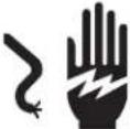 | If the extension cord is damaged, it must be replaced by the manufacturer (or its service agent) or a similarly qualified person to avoid a hazard. |
Test – transportskrue/rotor
- Start enheten og aktiver transportskruen (A, figur 9).
- Slipp transportskruespaken.
- Transportskruen må stanse på 5 sekunder eller mindre.
flowchart
graph TD
    A["Part No. xxxxxxxx"] --> B["XXXXXXXXXXXXXX"]
    B --> C["Serial No. xxxXXXXXXXXX"]
    C --> D["XXXXXXXXXXXXXXXXXX"]
    D --> E["XXXXXXXXXXXXXXXXXX"]
    E --> F["XXXXXXXXXXXXXXXXXX"]
    F --> G["CE 20xx"]
    G --> H["kg: xxx"]
    G --> I["kW: x.xx"]
    G --> J["xxxx max"]
    K["LwA"] --> L["XXX dB"]
    L --> M["I"]
    L --> N["H"]
    L --> O["C"]
    L --> P["D"]
Copyright © 2010 Briggs & Stratton Power Products Group, LLC
flowchart
graph TD
    A["Part No. xxxxxxxx"] --> B["XXXXXXXXXXXXXX"]
    B --> C["Serial No. xxxXXXXXXXXX"]
    C --> D["XXXXXXXXXXXXXXXXXX"]
    D --> E["XXXXXXXXXXXXXXXXXX"]
    E --> F["XXXXXXXXXXXXXX"]
    F --> G["CE 20xx"]
    G --> H["kg: xxx"]
    G --> I["kW: x.xx"]
    G --> J["xxxx max"]
    K["LWA"] --> L["XXX dB"]
    L --> M["I"]
    L --> N["H"]
    L --> O["C"]
    L --> P["D"]
    Q["F"] --> R["G"]
    R --> S["D"]
Copyright © 2010 Briggs & Stratton Power Products Group, LLC
flowchart
graph TD
    A["Part No. xxxxxxxx"] --> B["XXXXXXXXXXXXXX"]
    B --> C["Serial No. xxxXXXXXXXXX"]
    C --> D["XXXXXXXXXXXXXXXXXX"]
    D --> E["XXXXXXXXXXXXXXXXXX"]
    E --> F["XXXXXXXXXXXXXXXXXX"]
    F --> G["XXXXdB"]
    G --> H["CE 20xx"]
    H --> I["kg: xxx"]
    H --> J["kW: x.xx"]
    H --> K["xxxx max"]
    L["LEA"] --> G
    M["I"] --> G
    N["H"] --> G
    O["C"] --> G
    P["D"] --> G
    Q["F"] --> G
Copyright © 2010 Briggs & Stratton Power Products Group, LLC
flowchart
graph TD
    A["Part No. xxxxxxxx"] --> B["XXXXXXXXXXXXXX"]
    B --> C["Serial No. xxxXXXXXXXXX"]
    C --> D["XXXXXXXXXXXXXXXXXX"]
    D --> E["XXXXXXXXXXXXXXXXXX"]
    E --> F["XXXXXXXXXXXXXX"]
    F --> G["CE 20xx"]
    G --> H["kg: xxx kW: x.xx xxx max"]
    H --> I["I"]
    H --> J["H"]
    H --> K["C"]
    H --> L["D"]
    F --> M["F"]
    F --> N["G"]
* Below 40°F (4°C) the use of SAE 30 will result in hard starting.
** Above 80°F (27°C) the use of 10W-30 may cause increased oil consumption. Check oil level more frequently.
Serial No. xxxxxxxxxxxx
XXXdB
|
H
E
XXXXXXXXXXXXXXXXXXXXXX
XXXXXXXXXXXXXXXXXXXXXX
XXXXXXXXXXXXXXXXXXXXXX
XXXXXXXXXXXXXXXXXXXXXX
kg: xxx
kW: x.xx
20xx xxxx max
C
F
G
D
Copyright © 2010 Briggs & Stratton Power Products Group, LLC
Serial No. xxxxxxxxxxxx

|
H
E
XXXXXXXXXXXXXXXXXXXXXX
XXXXXXXXXXXXXXXXXXXXXX
XXXXXXXXXXXXXXXXXXXXXX
XXXXXXXXXXXXXXXXXXXXXX
kg: xxx
kW: x.xx
20xx xxxx max
C
F
G
D
Avtorske pravice © 2010 Briggs & Stratton Power Products Group, LLC
Vse pravice pridržane.
Kontrole snežne freze in delovne oznake (slika 2)
A — Nadzor svedra
B — Ročica za nadzor defl ektorja
C — Gumb za električni zagon
D — Vtičnica za napajalni kabel
E — Navodila za zagon / koraki od 1 do 3
F — Navodila za zagon / koraka 4 in 5
Kontrole motorja
G — Vzvod za hladen zagon
H — Rezervoar za gorivo in pokrov
I — Pokrov posode za olje (podaljšana merilna palica za količino olja)
J — Vbrizgalni gumb
K — Ključ za VKLOP/IZKLOP ali potisni/potegni (glede na vrsto priložene opreme)
L — Ročica zaganjalne vrvi
M — Izpust olja

OPOZORILO
flowchart
graph TD
    A["Part No. xxxxxxxx"] --> B["XXXXXXXXXXXXXX"]
    B --> C["Serial No. xxxXXXXXXXXX"]
    C --> D["XXXXXXXXXXXXXXXXXX"]
    D --> E["XXXXXXXXXXXXXXXXXX"]
    E --> F["XXXXXXXXXXXXXX"]
    F --> G["CE 20xx"]
    G --> H["kg: xxx"]
    G --> I["kW: x.xx"]
    G --> J["xxxx max"]
    K["LWA"] --> L["XXX dB"]
    L --> M["I"]
    L --> N["H"]
    L --> O["C"]
    L --> P["D"]
    Q["F"] --> R["G"]
    R --> S["D"]
Copyright © 2010 Briggs & Stratton Power Products Group, LLC
Minden jog fenntartva.
A Murray a Briggs & Stratton Power Products Group, LLC Milwaukee, WI USA védjegye.
Briggs & Stratton Power Products Group, LLC
P.O. Box 702
Milwaukee, WI USA 53201-0702
BRIGGSandSTRATTON.com
murray.com
CE
- Single Stage Snowthrower
- General Information
- Product Reference Data
- Operator Safety
- Hazard Symbols and Meanings Control Symbols on Equipment
- Safety Alert Symbol and Signal Words
- WARNING
- DANGER
- Snowthrower Controls and Operation Decals (Figure 2)
- Engine Controls
- Check / Add Oil
- Fuel Recommendations
- Fuel must meet these requirements:
- High Altitude
- Add Fuel
- Start the Engine
- Start the engine as follows:
- Stop the Engine
- Operate the Snowthrower
- Stop the Snowthrower
- Snowthrower Safety Test
- Test - Auger/Impeller
- Discharge Chute and Defl ector
- Manual Chute Rotation
- Remote Chute Rotation (if equipped)
- Manual Deflector Adjustment
- Quick Deflector Adjustment (if equipped)
- Clear a Clogged Discharge Chute
- Operating Tips
- Emissions Control Statement
- Change the Oil
- Remove Oil
- Add Oil
- Access the Spark Plug
- Auger Cable Adjustment
- Inspection
- Adjustment
- Storage
- Fuel System
- Engine Oil
- Snowthrower
- Remove from Storage
- \* Engine Power Rating Information
- Table des matières
- Test – transportskrue/rotor
- Kontrole snežne freze in delovne oznake (slika 2)
- Kontrole motorja
- OPOZORILO
Brand : NAC
Model : MS55800E
Category : Snow blower