CL61750R - Snow blower NAC - Free user manual and instructions
Find the device manual for free CL61750R NAC in PDF.


| Product type | Thermal snow thrower |
| Brand | NAC |
| Model | CL61750R |
| Engine | Gasoline (Briggs & Stratton engine) |
| Starting | Electric (with extension cord) and manual (recoil starter) |
| Clearing width | 61 cm (24 in) estimated |
| Snow removal capacity | Maximum depth: approx. 30 cm, width: 61 cm |
| Speeds | 5 forward and 2 reverse |
| Drive type | Traction clutch with Free Hand™ control |
| Chute direction | Manual (rod) or electric (depending on version) |
| Deflector | Adjustable manually or electrically |
| Heated handles | Yes (high/off/low switch) |
| Safety system | Emergency stop, auger control with 5-second stop, safety lock |
| Tires | Pneumatic, check pressure regularly |
| Lubrication | Lubrication of auger gears, transmission (depending on version) |
| Maintenance | Oil change, spark plug replacement, cable lubrication |
| Spare parts | Shear pins, spark plugs, belts (available at authorized dealer) |
| Weight | Approximately 70 kg |
Frequently Asked Questions - CL61750R NAC
User questions about CL61750R NAC
0 question about this device. Answer the ones you know or ask your own.
Ask a new question about this device
Download the instructions for your Snow blower in PDF format for free! Find your manual CL61750R - NAC and take your electronic device back in hand. On this page are published all the documents necessary for the use of your device. CL61750R by NAC.
USER MANUAL CL61750R NAC
natural_image
Black-and-white photo of a person operating a snowman in a field, with bare trees and a vehicle in the background (no visible text or symbols)Part No.: 1752194
Revision: F
natural_image
Technical line drawing of a mechanical device with an inset showing a close-up of a component (no text or symbols present)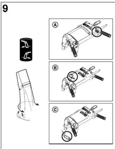

flowchart
graph TD
    A["Step 1: Initial mechanical component"] --> B["Step 2: After assembly"]
    B --> C["Final assembly with labeled parts"]
    style A fill:#f9f,stroke:#333
    style B fill:#bbf,stroke:#333
natural_image
Technical line drawing of a small utility vehicle with visible motors and wheels, shown from two different angles (no text or labels)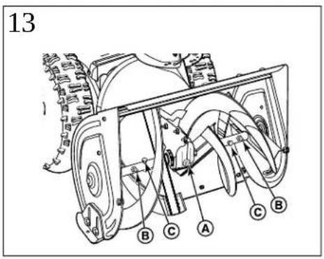
natural_image
Line drawing of a small utility snowman with visible blades and wheels (no text or symbols)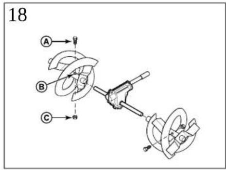
Products Covered by This Manual
CAUTION indicates a hazard which, if not avoided, could result in minor or moderate
injury.
The following products are covered by this manual:
1695856, 1695994, 1695995, 1695996, 1695997, 1696009, 1696010, 1696011, MOTRCE2, addresses practices not related to personal injury.
1696053, 1696054,1696055, 1696056, 1696061, 1696062, 1696063, 1696065, 1696066,
1696067, 1696301, 1695996-00, 1695997-00, 1696011-00, 1696012-00, 1696055-00
1696062-00, 1696199-00,1696200-00, 1696201-00, 1696202-00, 1696203-00.
1696207-00, 1696212-00, 1696220-00, 1696221-00, 1696222-00, 1696223-00.
1696226-00, 1696227-00, 1696228-00, 1696229-00, 1696230-00, 1696253-00,
1696255-00. 1696256-00. 1696257-00. 1696277-00. 1696278-00. 1696300-00.
1696302-00. 1696381-00. 1696382-00. 1696390-00. 1696391-00. 1696392-00.
1695997-01, 1696011-01, 1696012-01, 1696055-01, 1696062-01, 1696199-01.
1696202-01. 1696203-01. 1696207-01. 1696212-01. 1696221-01. 1696222-01.
1696224-01. 1696227-01. 1696253-01. 1696254-01. 1696255-01. 1696256-01.
1695996-02, 1695997-02, 1696011-02, 1696012-02
Manual Contents:
Operator Safety
Safety System Tests
Features and Controls
Operation
Maintenance 1
Troubleshooting 1
© 2013 Briggs & Stratton Corporation, Milwaukee, WI, USA. All rights res
The images in this document are representative, and are meant to compl instructional copy they accompany. Your unit may vary from the images of and RIGHT are as seen from the operator's position.
Operator Safety
Discharge Chute Warning

DANGER


Amputation hazard
The discharge chute contains a rotating impeller to throw snow. I quickly become caught in the impeller. Never clear or unclog the with your hands. Always use a clean-out tool.
Failure to observe these safety instructions will result in traumatic or severe laceration.
Hand contact with the rotating impeller inside the discharge chute is the cause of injury associated with snowthrowers. Never use your hands to discharge chute.
To safely clear a clogged discharge chute, follow these instructions:
1. Shut OFF the engine.
2. Wait 10 seconds to be sure the impeller blades have stopped rotating
3. Always use a clean-out tool, not your hands.
Safety Alert Symbol and Signal Wo
The safety alert symbol indicates a potential personal injury hazard. A sig (DANGER, WARNING, or CAUTION) is used with the alert symbol to des
or level of hazard seriousness. Asafety symbol maybe used to represent
The signal word NOTICE is used to address practices not related to per

DANGER indicates a hazard which, if not avoided, will result in death or serious
injury.

WARNING indicates a hazard which, if not avoided, could result in death or serious
injury.
Hazard Symbol Charts
224-00 Snowthrower Hazard Symbols
| Symbol | Meaning | Symbol | Meaning |
996-01,20' 21,22  25 25 | Safety information about hazards that can result personal injury. |  | Read and understand the operator's manual before operating or servicing the |
| Amputation hazard - rotating impeller. | Read the operator's manual before performing service. | ||
 | Amputation hazard - rotat impeller. |  | Amputation hazard - rotating auger |
 | Amputation hazard - touch moving parts. |  | Thrown objects hazard. |
 | Fire hazard. |  | Explosion hazard. |
 | Shock hazard. |  | Toxic fume hazard. |
| G8CZ | Hot surface hazard. |  | Ear protection recommended for extended use. |
 | Keep a safe distance. |  | Remove the key before performing service. |
 | Keep children away. |  | Kickback hazard. |
General Safety Warnings
Read an the Manual
scharge chute


This snowthrower is capable of amputating hands and feet and throwing Read and observe all the safety instructions in this manual. Failure to result comm death or serious injury.
lean out the


Read the operator's manuals before operating the machine. This machine is dangerous if used carelessly.
- Save these original instructions for future reference.
- Never operate the snowthrower without all guards, covers, shields, and other protection devices in place and working.
Stop the engine whenever leaving the operating position.
- Stop the engine and remove the key before unclogging the impeller housi word discharge chute, and before making repairs or adjustments.
ate a degree •typ/whenfacing the machine, remove the key.
Injury to reduce the risk of fire, keep the machine clean and free from spilled debris.


Read, understand, and follow all the instructions on the snowthrower and operator's manual before operating this unit. Failure to observe the safety instructions in this manual could result in death or serious injury.
- Be thoroughly familiar with the controls and the proper use of the snowthrower. Always place containers on the ground, away from your vehicle, before fil
• Make sure you are properly trained before operating the snowthrower. • When practical remove gas-powered equipment from the truck or trailer ar - Know how to stop the unit and disengage the controls quickly. on the ground. If this is not possible, then refuel such equipment on a portable container, rather than from a gasoline dispenser nozzle.
- Never allow anyone to operate the snowthrower without proper instruction.
- Always follow the instructions in the operator's manual, if the snowthrower will be needed, will be until refueling is complete. Do not use a nozzle lock-open device, stored for an extended period. Maintain or replace safety and instruction labels as necessary.
- Replace gasoline cap securely and allow spilled fuel evaporate before start
- Never attempt to make major repairs on the snowthrower unless you have been properly trained. Improper servicing of the snowthrower can result in hazardous operation, equipment damage, and voiding of the product warranty. Do not overfill the fuel tank. To allow for the expansion of gasoline, do the bottom of the fuel tank neck.
Operation and Equipment Safety

WARNING
This snowthrower is only as safe as the operator. If it is misused, maintained, it can be dangerous. Remember: you are responsible for and that of those around you.
- Keepfuel away from sparks, open flames, pilot lights, heat, and other igni
- Check fuel lines, cap, and fittings frequently for cracks or leaks. Replace
- Use an approved fuel container.
- If fuel spills, wait until it evaporates before starting engine.
or not fu properlypilled on clothing, change clothing immediately.
your safety
When starting the engine:
- Keep the area of operation clear of all persons, particularly small children • Ensure that spark plug, huller, fuel cap, and air cleaner (if equipped) a and pets and secured.
- Thoroughly inspect the area where the snowthrower will be used and remove all deormats, sleds, boards, wires, and other foreign objects. Do not crank the engine with the spark plug removed.
- Do not operate the snowthrower without wearing adequate winter clothing.
- Wear footwear that will improve footing on slippery surfaces. Use caution to avoid dissipated. slipping or falling especially when operating the snowthrower in reverse. Do not over-prime the engine. Follow the engine starting instructions in the
- Never operate the snowthrower without good visibility or light.
- If the engine floods set choke (if equipped) to OPEN/RUN position move
• Disengage the auger while transporting.
• Always be sure of your footing, and keep a firm hold on the handle. When Walk operating the equipment: - Do not clear snow across the face of slopes. Use extreme caution when changing direction on slopes. Do not attempt to clear steep slopes.
- Do not tip the snowthrower at an angle which causes the fuel to spill.
- Do not overload the machine capacity by attempting to clear snow too quickly.
- Never operate the snowthrower at high transport speeds on slippery surfaces (look equipped) removed.
- Do not use the snowthrower on surfaces above ground level such as roofs or buildings. If you drain the oil from the top oil fill tube, the fuel tank must be e residences, garages, porches, or other such structures or buildings.
- Operators should evaluate their ability to operate the snowthrower safely enough to. When transporting equipment:
protect themselves and others from injury. • Transport with fuel tank EMPTY, or with fuel shut-off valve OFF. - The snowthrower is intended to remove snow only. Do not use the snowthrower for any other purpose. When storing gasoline or equipment with fuel in the tank:
- Do not carry passengers.
- After striking a foreign object, shut OFF the engine, disconnect the cord on electric
- Gasoline is highly flammable and its vapors are explosive. Fumes may tract distant ignition source and an explosion and/or fire may result.
motors, thoroughly inspect the snowthrower for any damage, and repair the Handlage gasoline carefully. Never store a unit, with fuel in the tank, indoc before restarting and operating the snowthrower. ventilated enclosure where fuel fumes could reach an open flame, spark, - If the snowthrower vibrates abnormally, shut OFF the engine. Vibration is such as a furnace, water heater, or clothes dryer.
warning of trouble. See an authorized dealer if necessary for repairs. • Store away from furnaces, stoves, water heaters, or other appliances that - For models equipped with electric starting motors, disconnect the power cord after other ignition source because they can ignite fuel vapors. The engine starts.
- Exercise extreme caution when operating on or crossing gravel drives, walks, or roads. Stay alert for hidden hazards or traffic.
- Run the machine a few minutes after throwing snow to prevent freeze-collector/impeller. DANGER Keep hands fast and clothing away from rotating parts. Rotating parts are
Fuel Handling

WARNING


Fuel and its vapors are extremely flammable and explosive. Always with extreme care.
Failure to observe these safety instructions can cause a fire or could result in severe burns or death.
When adding fuel:
- Never add fuel to a running engine or to a hot engine.
- Turn off engine and let cool at least 2 minutes before removing the fuel.
- Fill fuel tank outdoors or in a well ventilated area.
Moving Parts walks for roads

the DANGER


Keep hands, feet, and clothing away from rotating parts. Rotating parts can or entangle hands, feet, hair, clothing, or accessories.
Failure to observe these safety instructions will result in traumatic amput or severe laceration.
- Whenever cleaning, repairing, or inspecting the snowthrower, make sure the handle is OFF, the engine key is removed, and all moving parts have stopped.
-
Do not put hands or feet near or under rotating parts. Keep clear of the lesionopwhich at all times.
-
Never operate the snowthrower without proper guards, and other safety de place and working.
- Never leave the snowthrower unattended while engine is running. Always do the auger and traction controls, stop engine, and remove keys.
fuel keep and loosing clothing away from the front of the snowthrower and aug mittens, dangling drawstrings, loose clothes, and pants can quickly become in the rotating device and amputation will occur. Tie up long hair and
- Run the machine a few minutes after discharging snow to prevent freeze-up of the collector/impeller.
- Disengage power to the collector/impeller when snowthrower is transported to not use.
Thrown Objects

WARNING

Objects can be picked up by the auger and thrown from the chute. Never stand charge on the engine outdoors. snow toward bystanders or allow anyone in front of the snowthrower. Failure to observe these safety instructions could result in death or serious injury. Do not run the engine in an enclosed area, even if doors and windows
adjustment or repair to protect eyes from foreign objects that may be machine.
- Always be aware of the direction the snow is being thrown. Nearby or property may be harmed by objects being thrown.
- Be aware of your environment while operating the snowthrower. Runni such as, gravel, doormats, newspapers, toys, and rocks hidden under be thrown from the chute or jam in the auger.
- Never operate the snowthrower near glass enclosures, automobiles, window wells,
drop-offs, and the like without proper adjustment of the discharge ch
- Familiarize yourself with the area in which you plan to operate the off boundaries of walkways and driveways.
• Always wear safety glasses or eye shields during operation, and while Ignitioning Source
• Use extreme caution when operating on or crossing gravel drives, walks, or roads. • If there is natural gas or IP gas leakage in the area do not start the
- Adjust the collector housing height to clear gravel or crushed rock surface. Do not use pressurize starting fluids because their vapors are flammable.

WARNING

Engines give off carbon monoxide, an odorless, colorless, poison gas.
Breathing carbon monoxide can cause nausea, fainting, or death.
Neveßtandischargen the engine outdoors.
. Failure to Do not run the engine in an enclosed area, even if doors and windows run.
Ignitioning Source

WARNING


Starting the engine creates sparking.
Sparking can ignite nearby flammable gasses.
Explosion and fire could result.
ks, • or roads. If there is natural gas or LP gas leakage in the area, do not start the
face. Do not use pressurize starting fluids because their vapors are flammable.
ow wells,
angle Hot Surfaces
Snowthrower Mark

WARNING


Running the engine produces heat. Engine parts, especially the muffler, is extremely hot.
Failure to observe these safety instructions could result in severe on contact.
nce of children.
Children

WARNING

Tragic accidents can occur if the operator is not alert to the pr Children are often attracted to the unit and the operating activity. that children will remain where you last saw them.
sence of children.
Never assume Never touch a hot engine or muffler. Allow muffler, engine cylinder, and before touching.
- Keep children out of the area during operation. Children are often equipment. Be mindful of all persons present.
- Be alert and turn the unit off if children enter the area.
- Never allow children to operate the unit.
- Use extra care when approaching blind corners, shrubs, trees, or other may obscure vision. Children may be present.
• Install and maintain in working order a spark arrester before using equipn forest-covered, grass-covered, or brush-covered unimproved land.
• U.S.A. Models: It is a violation of California Public Resource Code Section 4442 to
use or operate the engine on or near any forest-covered, brush-covered, grass-covered land unless the exhaust system is equipped with a spark a meeting any applicable local or state laws. Other states or federal areas similar laws.
Engine Safety

WARNING
Safe operation of the snowthrower requires the proper care and ma the engine. Failure to observe the safety instructions in this manual in death or serious injury.
- Disengage all clutches and shift into neutral before starting the engine
- Let the engine adjust to outdoor temperature before starting to clear
- Use extension cords and receptacles as specified by the manufacturer with electric drive motors or electric starting motors.
- Use a grounded three-wire plug-in for all snowthrowers equipped with motors or electric starting motors.

WARNING
Kickback hazard

Rapid retraction of the starter cord (kickback) will pull your hand the engine faster than you can let go. Broken bones, fractures, I could result.
When starting engine, pull the starter cord slowly until resistance pull rapidly to avoid kickback.
Maintenance and Storage

WARNING
could result This snowthrower must be properly maintained to ensure safe operation performance. Failure to observe the safety instructions in this manual cou in death or serious injury.
snow. When performing any maintenance or repairs on the snowthrower, shut OF engine, wait for all moving parts to stop, and remove the engine key to for all units someone from accidentally starting the engine.
- Check shear bolts and other hardware at frequent intervals for proper tigh electric drive. Sure the snowthrower is in safe working condition.
- Keep nuts and bolts tight and keep snowthrower in good condition.
- Never tamper with safety devices. Check their proper operation regularly a necessary repairs if they are not functioning properly.
- Components are subject to wear, damage, and deterioration. Frequently che components and replace with recommended parts, when necessary.
uises or sprains Check control operation frequently. Adjust and service as required. - Use only factory authorized replacement parts, or equivalent, when making s felt and then Always comply with factory specifications on all settings and adjustments.
- Only authorized service locations should be utilized for major service and requirements.
- Use only attachments and accessories approved by the factory, or equivale as wheel weights, counterweights, or cabs).
- Never attempt to make any adjustments while the engine is running (exceeds specifically recommended by the factory).
- Always refer to the operator's manual for important details if the snowthrower is to be stored for an extended period of time.
Safety Decals
Before operating your unit, read the safety decals. The cautions and warm safety. To avoid a personal injury or damage to the unit, understand and decals.

WARNING
If any safety decals become worn or damaged, and cannot be read, decals from your local dealer.
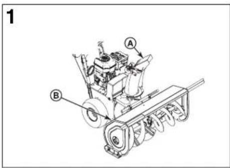
| Chute Danger DecalA | 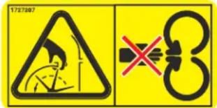 | |
| Auger Danger DecalB | 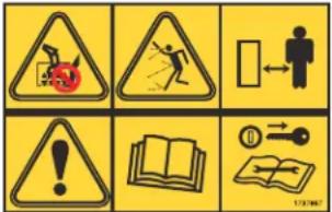 |
Safety System Test (units with Free control)

all the safe

Amputation hazard
This snowthrower is equipped with several mechanical safety systems designed the error for safe while using the unit. Check the operation of these systems using the safety system tests listed. If the unit fails to operate as described operate it. See your authorized dealer for service immediately.
Test 1 - Auger/Impeller Control
With the engine running:
- Press down on the auger control lever. (The auger/impeller should rotate)
- Release the auger control lever. (The auger/impeller should stop within 5
Test 2 - Traction Drive Control
With the engine running and speed control in 1st gear:
- Press down on the traction control lever. (The unit should move forward
- Release the traction control lever. (The unit should stop)
Test 3 - Free Hand Control
With the engine running:
- Engage the auger and traction control levers, then release the auger coil (Both controls should remain engaged)
- Next, release the traction control lever. (Both controls should release)
Safety System Tests
Determining Which Test to Use
Models with Free Hand™ Control: After engaging the traction control (left hand) and auger control (right hand), Free Hand allows the operator to release the auger control, and for the auger control to remain engaged until the traction control is released. Free Hand models have the icon set shown in Figure 2 on the dashboard.
Models without Free Hand Control: On units without Free Hand, the aug controls operate independently, and the Free Hand icon set is not found
Please select the appropriate Safety System Test for your unit.
Safety System Test (units without Hand control)

WARNING

Amputation hazard
This snowthrower is equipped with several mechanical safety systems designed to keep the operator safe while using the unit. Check the operation of these systems regularly using the safety system tests listed. If the unit fails to operate as described, DO NOT operate it. See your authorized dealer for service immediately.
Test 1 - Auger/Impeller Control
With the engine running:
- Press down on the auger control lever. (The auger/impeller should
- Release the auger control lever. (The auger/impeller should stop w
Test 2 - Traction Drive Control
With the engine running and speed control in 1st gear:
- Press down on the traction control lever. (The unit should move
- Release the traction control lever. (The unit should stop)
Features and Controls
Engine Features and Controls
auger control, and for engine features and controls, please refer to the engine operator's manual.
Snowthrower Features and Controls
| on the dashboard. | Local DescriptionIcon | |
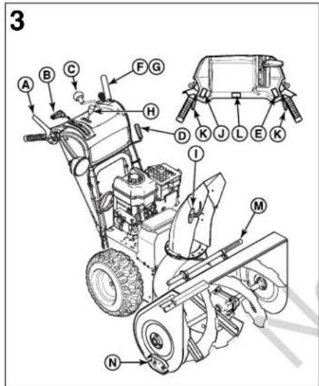
| AFree | Auger Control Lever - Used to engage disengage the auger and impeller. To push down. To disengage, release. | |
| Bned to keeptems regularly ribed, DO NOT | Speed Select Lever - Allows the opera select forward and reverse speeds. To s speed select lever to desired position.NOTE: Do not move speed select lev Traction Control is engaged. This may in severe damage to the drive system | |
| Chute Rotation Crank - In-Dash (if ed Used to rotate the discharge chute to right. | ||
| D(rotate)E5 seconds) | Chute Rotation Crank - Lefthand Cran equipped)- Used to rotate the discharge the left or right. | |
| Chute Rotation Switch - Electric (if eUsed to rotate the discharge chute to right. | ||
| Fward) | Free HandTM Control (if equipped)- After engaging the traction control (left hand) control (right hand), allows the operator the auger control lever to use other co | |
| G | Traction Control Lever - Used to prop snowthrower forward or reverse. Push do engage, release to disengage. See also, "Free-Hand Control". |
| DescriptionIconLocation | |||
| H |  | Deflector Control - In-Dash (if equipped) to control the angle of the deflector (up or down). | DANGERToxic fume hazardUsed Engines give off carbon monoxide, an odorless, colorless, poison gBreathing carbon monoxide can cause nausea, fainting, or death.Used Start and run the engine outdoors.Do not start or run the engine in an enclosed area, even if do open. |
| I | [56X8] | Deflector Control - Manual (if equipped) to control the angle of the deflector (up or down). | |
| J |  | Deflector Control - Electric (if equipped) to control the angle of the deflector (up or down). | |
| K | 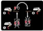 | Easy TurnTM Traction Control (if equipped) - When engaged, allows the operator to release one drive wheel, but allows the other wheel to continue driving for easy turning. | |
| L | [23X2] | Grip Warmer Switch (if equipped) - Used Thrown objects hazardwarm the hand grips (high, off, low). | |
| -M | Clean-Out Tool - Used to remove snow and debris from the discharge chute and the auger housing.Be sure the operating area is clear of bystanders. Never direct the d anyone, or toward buildings or cars. | ||
| -N | Skid Shoes - Used to adjust the ground clearance of the auger housing. | ||
eration
Before Operating the Snowthrower

WARNING



Read the operator's manual before operating the machine. This machine dangerous if used carelessly.
- Never operate the snowthrower without all guards, covers, and shield
- Stop the engine whenever leaving the operating position.
- Remove the key before unclogging the impeller housing or discharge before making repairs or adjustments.
- When leaving the machine, remove the key.
- To reduce the risk of fire, keep the machine clean and free from and debris.
- On electric start models, disconnect the extension cord before operating.
- Be sure to check the engine oil level before starting the engine. See operator's manual for oil recommendations.
- Rotate the chute rotation crank (C or D, Figure 3) or use the chute rotate to set the direction of the discharge chute.
- Models with manual defector adjustment: Loosen the wingnut securing the deflector (I). Raise the deflector to throw snow further. Set the defector 1 position and tighten the wingnut.
Models with in-dash deflector control lever: Use the deflector control le move the deflector up or down. Raise the deflector to throw snow furthe
Models with electric deflector control: Use the deflector control switch (the deflector up or down. Raise the deflector to throw snow further.
ne can be 4. Use the speed select lever (B) to select the forward or reverse drive spe speeds when clearing wet, heavy snow. Use higher speeds for light snow transporting. in place.
NOTE: Always set engine speed to FAST (full throttle).
chute and
-
Fully press the auger control lever (A) to engage the auger. Release the the auger.
-
Fully press and hold the traction control lever / Free Hand control (F/G) spilled traction olive and begin moving the snowthrower. To stop, release the lev
NOTE: Always release the traction control lever before changing speeds.
-
When both the auger (A) and traction control levers (F) are pressed, the control is activated. This allows you to release the auger control lever (A controls. The auger will continue to rotate until the traction control lever/Fi control lever is released.
-
If desired, if equipped, use the grip warmer switch (L) to turn on the he
Operating the Snowthrower

DANGER


Amputation hazard
The discharge chute contains a rotating impeller to throw snow. I quickly become caught in the impeller. Never clear or unclog the with your hands. Always use a clean-out tool.
Failure to observe these safety instructions will result in traumatic or severe laceration.
Hand contact with the rotating impeller inside the discharge chute is the cause of injury associated with snowthrowers. Never use your hands to discharge chute.
To safely clear a clogged discharge chute, follow these instructions:
- Shut OFF the engine.
- Wait 10 seconds to be sure the impeller blades have stopped rotati
- Always use a clean-out tool, not your hands.
Stopping the Snowthrower
-
Release the auger control lever (A, Figure 1).
-
Release the traction control lever (F).
discharge chute engine. Please refer to the engine operator's manual for engine i
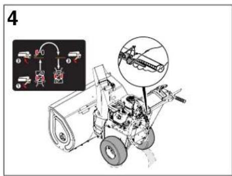
Easy Turn™ Traction Control (if equipped)
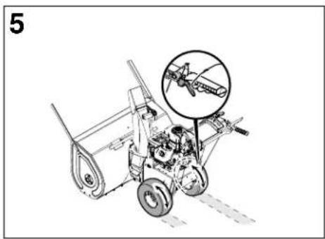
For easy turning when using the snowthrower, squeeze the Easy Turn traction (Figure 4) instead common
clean_out_the NOTE: The Easy Turn will be more difficult to activate under a heavy load. lever before beginning a turn.
Engaging the Easy Turn traction control lever releases one of the traction when the other wheel to continue driving. Releasing the Easy Turn traction control is automatically engages both drive wheels for full traction (Figure 5).
Wheel Release - Lock Knob (if equip
Some models are equipped with a drive wheel release that allows you to dis the drive wheels, for easier transporting of the unit with the engine off.
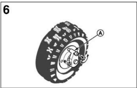
Models with Traction Lock Knob: Wheels equipped with a traction lock (6) can be completely released by pulling the knob out away from the wheel pin is disengaged from the wheel. Then rotate the knob so the pin does wheel. Reverse this process to engage the drive wheel.
Wheel Release - Lock Pins (if equ
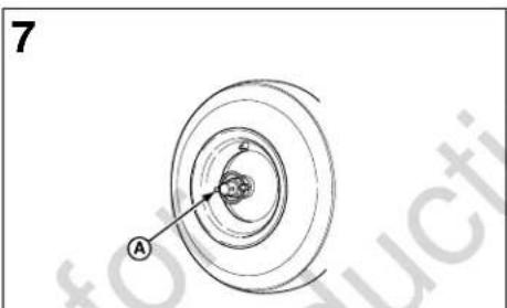
Wheels equipped with a traction lock pin (A, Figure 7) can be completely removing the pin and installing it in the outer axle hole. Reverse this pro drive wheel.
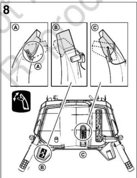
Deflector Adjustment
A. Manual Deflector Control (if equipped)
Loosen the deflector knob (A, Figure 8), adjust the deflector to the desire then tighten the knob to secure. Raise the deflector to throw snow further
B. Electric Deflector Control (if equipped)
While the engine is running, press either side of the deflector control swit move the deflector up and down. Raise the deflector to throw snow further
C. In-Dash Deflector Control (if equipped)
Move the deflector control lever (C, Figure 8) forward or backward to raise deflector. Raise the deflector to throw snow further.
Chute Rotation Adjustment
A. Electric Chute Rotation Control (if equipped)
While the engine is running, press either side of the chute rotation switch rotate the chute left or right.
B. In-Dash Chute Rotation Control (if equipped)
Locate the in-dash chute rotation crank (B, Figure 9). Rotate the crank to
C. Lefthand Crank Chute Rotation Control (if equipped)
Locate the lefthand chute rotation crank (C, Figure 9) Rotate the crank to
Skid (A Figure the locking) Shoe Height Adjustment
Amputation hazard
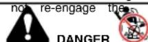
The discharge chute contains a rotating impeller to throw snow. Fingers can be raised byght and traumatic amputation or severe laceration will result. Hand cash the engaging trimpeller inside the discharge chute is the most common cau associated with snowthrowers.
Turn the engine OFF, wait for all moving parts to stop, and remove performing any maintenance or repairs.
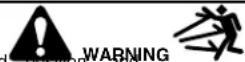
Thrown objects hazard
Objects such as gravel, rocks, or other debris, if struck by the impeller, may with sufficient force to cause personal injury, property damage, or damage to which (8th Figure 8) to
'Be sure to set the skid shoes at the proper height to maintain ground clea type of surface being cleared.
This is snowthrower is equipped with two height adjust skids, secured to the out auger housing. These elevate the front of the snowthrower.
When removing snow from a hard surface area such as a paved driveway of the skids up to bring the front of the snowthrower down.
When removing snow from rock or uneven construction, raise the front of the by moving the skids down. This will help to prevent rocks and other debris
up(A,anFigureown) by the augers.
-
Determine how much clearance you want between the scraper bar at the the auger housing and the ground. If clearing a gravel surface, enough clearance is needed to prevent the unit from picking up rocks.
-
Place a block equal to the desired ground clearance under the scraper ba
-
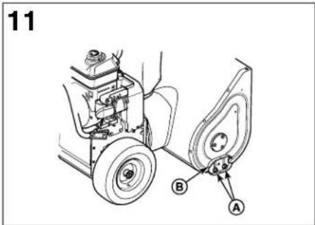
Loosen the skid shoe mounting nuts (A, Figure 11) and push the skid sh until it touches the ground. Re-tighten mounting nuts.
-
roBte the skidte.shoe on the other side at the same height.
Filling the Fuel Tank
Please refer to the engine operator's manual for information about filling for fuel recommendations.
Clearing a Clogged Discharge Chute

DANGER


Amputation hazard
The discharge chute contains a rotating impeller to throw snow. I quickly become caught in the impeller. Never clear or unclog the with your hands. Always use a clean-out tool.
Failure to observe these safety instructions will result in traumatic or severe laceration.
Hand contact with the rotating impeller inside the discharge chute is the cause of injury associated with snowthrowers. Never use your hands to discharge chute.
To safely clear a clogged discharge chute, follow these instructions:
- Shut OFF the engine.
- Wait 10 seconds to be sure the impeller blades have stopped rotating
- Always use a clean-out tool, not your hands.
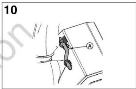
A clean-out tool (A, Figure 10) is provided with the unit.
Off-Season Storage
if fuel tank, and be stored for 30 days or more at the end of the season, are recommended to prepare it for storage. Always refer to the operator's man important details if the unit is to be stored for an extended period.
Please refer to the engine operator's manual for engine storage information.
NOTE: Fuel must be removed or treated to prevent gum deposits from forming filter, hose, and carburetor during storage.

WARNING


dischargeandhusplosion hazard
Gasoline is highly flammable and its vapors are explosive. Fumes may travel impuration source and an explosion and/or fire may result.
Handle gasoline carefully. Never store the unit, with fuel in the tank, indoors must be enclosed by enclosure where fuel fumes could reach an open flame, spark, pilot eas autfuathace, water heater, or clothes dryer.
• Thoroughly clean the unit.
- Lubricate all lubrication points (see Maintenance section).
- Make sure all nuts, bolts, and screws are securely fastened. Inspect all parts for damage, breakage, and wear. Replace if necessary.
- Touch up all rusted or chipped paint surfaces; sand lightly before painting
- Cover the bare metal parts of the snowthrower housing auger, and the i rust preventative.
- If possible, store your unit indoors and cover it to give protection from
- If the machine must be stored outdoors, cover with a heavy tarpaulin.
To Return to Service:
- Fill the fuel tank with a fresh fuel.
• Make sure all fasteners are tight.
• Make sure all guards, shields, and covers are in place.
Maintenance
Maintenance Schedule
| Before Each Use |
| Check engine oil levelPerform Safety System Test |
| Every 8 Hours or Daily |
| Check engine oil level |
| Every 25 Hours or Annually |
| Lubricate control lever linkageLubricate the auger assemblyLubricate the discharge chute rotation gear and deflectorLubricate the drive system hex shaft with 5w-30 synthetic motor of greaseLubricate the disc drive system (if equipped) |
| Every 50 Hours or Annually |
| Check muffler and spark arrester (if equipped)Check tire pressure |
Engine Maintenance
For engine maintenance schedules and procedures, please refer to the engine manual.
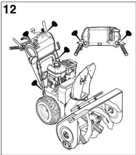
Control Lever Linkage Lubrication
Check the function of the Free Hand control (A, Figure 12). The controls described in the Operation section.

WARNING

Amputation hazard
It is critical for safe operation of the unit that the controls disengage no circumstances should the unit be used if the controls do not func Safety Systems Tests to confirm correct operation.
Lubricate the linkage for the Free Hand control, speed select control, and Steer control every ten operating hours, or as necessary to ensure safe
Auger Assembly Lubrication
Lubricate Auger Gear Box
The auger gear box is lubricated at the factory and should not require if for some reason the lubricant should leak out, or if the auger gear add Lubriplate GR132 Grease or equivalent. Maximum 3-1/4 ounces, (92 be used.
Remove filler plug (A, Figure 13), once a year to check grease level. If not add. If grease is not visible, use a piece of fine wire, like a dipst grease in the gear box.
Lubricate Auger Shaft Fittings
Using a grease gun, lubricate the auger shaft fittings (B, Figure 13) every or once per season. Each time a shear bolt or pin (C) is replaced, the greased.
For storage or when replacing shear bolts or pins, remove the shear bolts lubricate the shaft fittings (B), and rotate the augers several times to distri Reinstall the shear bolts or pins when complete.
Discharge Chute and Deflector Lubric
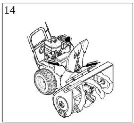
Lubricate the chute rotation gear (Figure 14) with grease, and the deflector automotive type oil every twenty five operating hours.
Where an oil can is pictured, lubricate with engine oil. Where a grease lubricate with lithium grease.
Hex Shaft and Chain Lubrication
The hex shaft and drive chains must be lubricated at the interval specified in Chart. Please have your authorized dealer perform this maintenance.
Traction Cable Inspection
The cables are adjusted at the factory and no adjustment should be necessary if the cables have become stretched or are sagging, adjustment will be necessee your dealer for this adjustment.
Traction Drive Belt Adjustment
The traction drive belt is under constant spring tension and does not require any. If the traction drive belt is slipping, see your authorized dealer.
Speed Control Rod Adjustment
and chains with if the speed control rod requires adjustment, see an authorized dealer.
Easy Turn™ Cable Adjustment
If the Easy Turn cable has stretched, the gears will not disengage when the activated. Adjust the cable using the following procedure.
-
Turn the engine off and remove the key.
-
Loosen the jam nut (A, Figure 34).
- Turn the adjustment nut (B) to lengthen or shorten the cable. The cable tightened until all slack is removed from the lever. However, it must not Easy. Turn without depressing the control lever.
- Tighten the jam nut (A).
Auger Cable Adjustment

function

Amputation hazard
Over-tightening the auger cable may cause the auger drive to engage without the auger drive control.
when follow released. Adjustment procedure to ensure the cable is not over-tightened. on properly. See
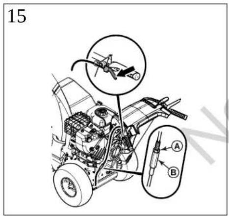
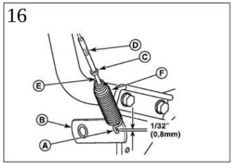
- With the auger control lever released, the hook (A, Figure 16) should bare lever (B) without raising it. There can be a maximum of 1/32" (0.8 mm)
Easy To Turn Easy to Tum, loose the nut (C) by holding the adjusting flats (D) and turn in operation. Then, turn the adjusting flats and hold the adjustment screw (E). The adj is a Phillips screw and the head can be held or turned by inserting a through the spring (F).
- Hold the adjusting flats and tighten the nut.
- Toensure that the auger does not engage unless the controlisfullydepressed, perform the Safety System Tests. The auger must stop within 5 seconds of the
additional lubrication control being released. Box has been serviced,
rams) should
Determine Which Shear Bolt/Pin System
You is visible do k to check if there
Please refer to the Illustrated Parts List to determine if your unit requires a shearbolt and spacer combination.

erating hours DANGER

auger shaft MUST Amputation hazard
The discharge chute contains a rotating impeller to throw snow. Fingers can become caught and traumatic amputation or severe laceration will result. Hand out the disease. with the rotating impeller inside the discharge chute is the most common cau associated with snowthrowers.
Turn the engine OFF, wait for all moving parts to stop, and remove the er performing any maintenance or repairs.
Shear Pin Replacement
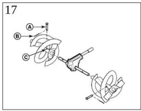
Augers are secured to the auger shaft with special pins that are designed to object becomes lodged in the auger housing. Use only factory spec, or equivai pins.
- Turn off the engine and wait for all moving parts to stop.
- Remove the existing shear pin.
- Lubricate the auger grease fittings and rotate the auger to lubricate
-
Align the shear pin holes. Install the new shear pin (A, Figure 17) shaft (C). Secure with a cotter pin (B).
-
Turn off the engine and wait for all moving parts to stop.
- Remove the existing shear bolt.
the3. augericaleft.the auger grease fittings. Spin the auger to lubricate the auger s
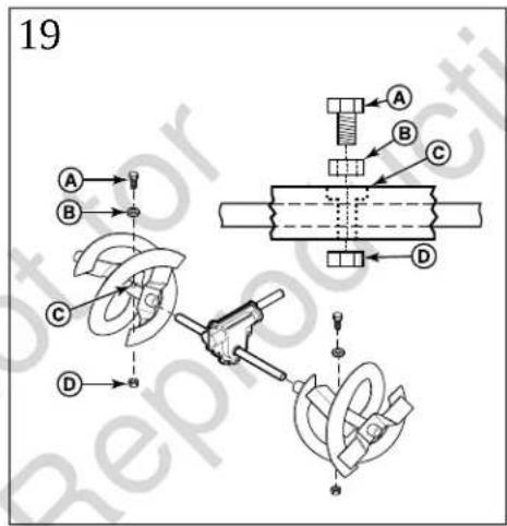
through the auger bolt and spacer holes. Install the new shear bolt (A, Figure 19) through the auger shaft (C). Secure with the locknut (D).
Shear Bolt Replacement
- Turn off the engine and wait for all moving parts to stop.
- Remove the existing shear bolt.
- Lubricate the auger grease fittings. Spin the auger to lubricate the auger shaft.
- Align the bolt holes. Install the new shear bolt (A, Figure 18) through the auger (B). Secure with the locknut (C).
Checking Tire Pressure
Tire pressure should be checked periodically. Recommended tire pressure varies manufacturer. A good rule of thumb is to inflate the tire up to, but not exc Inflation" stamped on the side-wall of the tire.
the auger shaft Gear Drive System (if equipped)
The gear drive system requires no maintenance or adjustment. Should you have with the gear drive system, contact your authorized service dealer.
Shear Bolt and Spacer Replacement
Augers are secured to the auger shaft with special bolts that are designed to break if an object becomes lodged in the auger housing. Use only factory spec, or equivalent, shear bolts.
Troubleshooting
Troubleshooting Chart
Perform the inspection or repair as indicated in the Troubleshooting Chart.
| RemedyLook forProblem | ||
| is released. | Free Hand control (if equipped) is ACTIVE.Auger | Releasemot hopauge within 50 seconds Faster Height control (level equipped) to stop auger. |
| See authorized dealer.Auger drive belt out of adjustment | ||
| See authorized dealer.Auger belt guide out of adjustment | ||
| See authorized dealer.Electrical failure.Discharge chute or lubrication. | ||
| Discharge chute or deflector does not work (remote-manual). lubrication. | Adjust and/or lubricate control linkage.Discharge chute or lubrication. | |
| Drive fails to move snowthrower at slow speeds. | Traction control out of adjustment. | See authorized dealer. |
| Engine fails to start. | Key is in OFF position. | Set key to ON position. |
| Failure to prime a cold engine. | Press primer button twice and restart. | |
| Fuel shut-off valve, if equipped, is in CLO | STED position to OPEN position. | |
| Out of fuel. | Fill fuel tank. | |
| Choke OFF - cold engine. | Turn choke ON, set throttle to FAST. | |
| Engine flooded. | Move the choke to OPEN/RUN position, move throttle to FAST position, and crank until the engine starts. | |
| See authorized dealer.No spark. | ||
| Engine starts hard or runs poorly. | Water in fuel, or old fuel. | Drain tank. (Dispose of fuel at an authorized hazardous facility.) Fill with fresh fuel. |
| See authorized dealer.Spark plug faulty, fouled, or gapped | ||
| Fuel cap vent is blocked. | Clear vent. | |
| Excessive vibration. | Loose parts or damaged impeller. | Stop engine immediately. Tighten all hardware. If continuous, have the unit serviced by an authorized dealer. |
| Snowthrower does not stop when traction control lever is released. | Traction control out of adjustment. | See authorized dealer. |
| Scraper bar does not clean hard surface. | Skid shoes and scraper bar improperly adjusted. | Raise or lower skid shoes and scraper bar. |
| Unit fails to propel itself. | Drive belt loose or damaged. | Replace drive belt. See authorized dealer. |
| See authorized dealer.Incorrect adjustment of traction driver. | ||
| Worn or damaged friction disc. | Replace friction disc. See authorized dealer.See authorized dealer.Auger drive belt loose or damage | |
| Auger control cable not adjusted correctly. | Adjust auger control cable. Refer to Maintenance this manual. | |
| Broken shear pin or shear bolt. | Replace shear pin or bolt. Refer to Maintenance section this manual, or see an authorized dealer. | |
| Discharge chute clogged. | Stop engine immediately. Always use the clean-out tool clear a clogged discharge chute, not your hands. Clear discharge chute and inside of auger housing. Refer to Discharge Chute Warning in the Operator Safety section. | |
| Foreign object lodged in auger. | Stop engine immediately. Always use the clean-out tool clear a clogged chute, not your hands. Remove object auger. Refer to WARNINGS in the Operator Safety sec | |
m = 311
1
[Non-Text]
m = 311
In
m
[Non-Text]
[Non-Text]
,
[Non-Text]
s
k
L
epi
per
Di
P
na
to
-
,
[Non-Text]
,
[Non-Text]
[Non-Text]
[Non-Text]
[Non-Text]
[Non-Text]
[Non-Text]
[Non-Text]
[Non-Text]
[Non-Text]
[Non-Text]
[Non-Text]
[Non-Text]
[Non-Text]
[Non-Text]
[Non-Text]
[Non-Text]
ci UR 1690 -00 240 224 227 301 996 201 223 257 13 1 7 3 20 v ni . . . . . . . . . . . . . . . . . . . . . . . . . . . . . . . . . . . . . . . . . . . . . . . . . . . . . . . . . . . . . . . . . . . . . . . . . . . . . . . . . . . . . . . . . . . . . . . . . . . . .
[Non-Text]
[Non-Text]
[Non-Text]
[Non-Text]
[Non-Text]
[Non-Text]
[Non-Text]
[Non-Text]
[Non-Text]
[Non-Text]
[Non-Text]
[Non-Text]
[Non-Text]
4
4
či
CI
LNET
UR
169
-00
06-0
\$224
227
201
501
996
\$201
\$223
\$257
F
1
1
m = 311
•
|
do
13
H
1
1
1
1
1
7
1
3
9
L
20
|
y
F
|
ni
-
-
The image contains no text or characters.
|
|
-
F
|
L
-
(1)
。
0
D
Pr
√
T
1.
1
Ta
Vaz
ta
[NO TEXT]
po
ru
1
ě
D
|
ne
-
,
[Non-Text]
[Non-Text]
■
In
2
[Non-Text]
。
[Non-Text]
cl
SI k
R
epre
ere
1
Pi
na
to
L
m = 311
The Ground Truth image displays a single, solid horizontal line. According to Rule 2 (UNDERSCORE & LINE RULES), this is a stylistic or background line, not a placeholder underscore. Therefore, the OCR result must ignore it and output nothing or only meaningful text. The provided OCR content is "____", which consists of four underscores. This is an incorrect interpretation of the line as a placeholder, violating the rule that stylistic lines must be ignored. The OCR has hallucinated underscores where none should exist based on the GT's visual context. Hence, the OCR result is inconsistent with the Ground Truth.
,
[Non-Text]
[Non-Text]
[Non-Text]
[Non-Text]
[Non-Text]
[Non-Text]
[Non-Text]
[Non-Text]
[Non-Text]
[Non-Text]
[Non-Text]
[Non-Text]
[Non-Text]
[Non-Text]
[Non-Text]
[Non-Text]
ci UR 1690 -00 Z 241 224 227 801 996 201 223 257 13 1 7 3 20 v ni O Př u L. Tj vej ta pc ru ě Pi ni In sl k epn erí Pi ni tc
[Non-Text]
[Non-Text]
[Non-Text]
[Non-Text]
[Non-Text]
[Non-Text]
[Non-Text]
[Non-Text]
[Non-Text]
[Non-Text]
[Non-Text]
[Non-Text]
[Non-Text]
•
m = 311
x!
CI
- MT
UR
1696
-00
06-0
\$224
227
The image is too blurry to recognize any text content.
VAROITUS

© 2013 Briggs & Stratton Corporation, Milwaukee, WI, USA. Minden jog
© 2013 Briggs & Stratton Corporation, Milwaukee, WI, USA. Tutti i diritti
© 2013 Briggs & Stratton Corporation, Milwaukee, WI, USA (JAV). Visos
Pasirinkite savo jrenginiui tinkamus saugos sistemu patikrinimus.
© 2013 Briggs & Stratton Corporation, Milwaukee, WI, USA. Alle rettigheter
Preizkusi varnostnega sistema
Izbira ustreznega preizkusa
- Products Covered by This Manual
- Manual Contents:
- Operator Safety
- Discharge Chute Warning
- Safety Alert Symbol and Signal Wo
- Hazard Symbol Charts
- General Safety Warnings
- Operation and Equipment Safety
- WARNING
- Fuel Handling
- When adding fuel:
- Moving Parts walks for roads
- the DANGER
- Thrown Objects
- Ignitioning Source
- Snowthrower Mark
- nce of children.
- Children
- sence of children.
- Engine Safety
- Kickback hazard
- Maintenance and Storage
- Safety Decals
- Safety System Test (units with Free control)
- Amputation hazard
- Test 1 - Auger/Impeller Control
- Test 2 - Traction Drive Control
- Test 3 - Free Hand Control
- Safety System Tests
- Determining Which Test to Use
- Safety System Test (units without Hand control)
- Features and Controls
- Engine Features and Controls
- Snowthrower Features and Controls
- eration
- Before Operating the Snowthrower
- Operating the Snowthrower
- Stopping the Snowthrower
- Easy Turn™ Traction Control (if equipped)
- Wheel Release - Lock Knob (if equip
- Wheel Release - Lock Pins (if equ
- Deflector Adjustment
- Manual Deflector Control (if equipped)
- Electric Deflector Control (if equipped)
- In-Dash Deflector Control (if equipped)
- Chute Rotation Adjustment
- Electric Chute Rotation Control (if equipped)
- In-Dash Chute Rotation Control (if equipped)
- Lefthand Crank Chute Rotation Control (if equipped)
- Skid (A Figure the locking) Shoe Height Adjustment
- Filling the Fuel Tank
- Clearing a Clogged Discharge Chute
- Off-Season Storage
- dischargeandhusplosion hazard
- To Return to Service:
- Maintenance
- Maintenance Schedule
- Engine Maintenance
- Control Lever Linkage Lubrication
- Auger Assembly Lubrication
- Lubricate Auger Gear Box
- Lubricate Auger Shaft Fittings
- Discharge Chute and Deflector Lubric
- Hex Shaft and Chain Lubrication
- Traction Cable Inspection
- Traction Drive Belt Adjustment
- Speed Control Rod Adjustment
- Easy Turn™ Cable Adjustment
- Auger Cable Adjustment
- Determine Which Shear Bolt/Pin System
- You is visible do k to check if there
- auger shaft MUST Amputation hazard
- Shear Pin Replacement
- Shear Bolt Replacement
- Checking Tire Pressure
- the auger shaft Gear Drive System (if equipped)
- Shear Bolt and Spacer Replacement
- Troubleshooting
- Troubleshooting Chart
- Preizkusi varnostnega sistema
- Izbira ustreznega preizkusa
Brand : NAC
Model : CL61750R
Category : Snow blower