CDP 75 MKII - Dehumidifier Dantherm - Free user manual and instructions
Find the device manual for free CDP 75 MKII Dantherm in PDF.


| Product Type | Refrigeration condensation dehumidifier |
| Brand | Dantherm |
| Model | CDP 75 MK II |
| Dimensions (H x W x D) | 650 x 1155 x 725 mm |
| Weight | 130 kg |
| Power supply | 1 × 230 V / 50 Hz |
| Max power consumption | 2.0 kW |
| Max current consumption | 9.5 A |
| Air flow rate | 1500 m³/h |
| Max available pressure | 140 Pa |
| Humidity range | 40–100 % RH |
| Temperature range | 20–38 °C |
| Refrigerant | R407C, charge 2.1 kg |
| Sound level | 58 dB(A) at 1 m |
| Condensate drainage | Drain hose Ø 3/4" with siphon |
| Fan type | Permanently lubricated, maintenance-free |
| Compressor protection | Klixon (single-phase) |
| Display and controls | LED diodes and push buttons for dehumidification, heating and ventilation |
| Control options | Hygrostat, room thermostat, defrost sensor |
| Mounting options | Floor, on shock-absorbing feet, wall console |
| Monthly maintenance | Cleaning of the suction filter and condensate tray |
| Annual maintenance | Internal cleaning (condenser, evaporator, fan) |
| Integrated safety | HP and LP pressure switch, start-up delay 75 s |
Frequently Asked Questions - CDP 75 MKII Dantherm
User questions about CDP 75 MKII Dantherm
0 question about this device. Answer the ones you know or ask your own.
Ask a new question about this device
Download the instructions for your Dehumidifier in PDF format for free! Find your manual CDP 75 MKII - Dantherm and take your electronic device back in hand. On this page are published all the documents necessary for the use of your device. CDP 75 MKII by Dantherm.
USER MANUAL CDP 75 MKII Dantherm
natural_image
Simple line drawing of a trash bin with crossed lines indicating no text or symbols (no text or labels)
| Emne/Topic/Thema/Chapitres/Tema | ||
| DA | DA-Introduktion | 4 |
| Generelle oplysninger | 5 | |
| Produkt- og funktionsbeskrivelse | 6 | |
| Display | 8 | |
| Hygrostat og ekstra styringsmuligheder | 11 | |
| Montage- og installationsvejledning | 13 | |
| Servicevejledning | 17 | |
| Fejlfindingsvejledning | 18 | |
| Teknisk information | 19 | |
| Serviceaftale | 20 | |
| EN | EN-Introduction | 21 |
| General information | 22 | |
| Product and functional description | 23 | |
| Display | 25 | |
| Hygrostat and other control options | 11 | |
| Mounting and installation instructions | 30 | |
| Service guide | 34 | |
| Fault finding guide | 35 | |
| Technical information | 36 | |
| Service agreement | 37 | |
| DE | DE-Introduktion | 38 |
| Allgemeine Informationen | 39 | |
| Produkt- und Funktionsbeschreibung | 40 | |
| Display | 42 | |
| Hygrostat und zusätzliche Steuerungsmöglichkeiten | 11 | |
| Montage- und Installationsanleitung | 47 | |
| Wartungsanleitung | 51 | |
| Fehlersucheanleitung | 52 | |
| Technische Informationen | 53 | |
| Service-Vereinbarung | 54 | |
Fortsættes/continued overleaf/fortsetzt/Suite à la page suivante/Продолжение на след. стр./
continua alla pagina seguente
| Emne/Topic/Thema/Chapitres/Tema | ||
| FR | FR-Introduction | 55 |
| Informations générales | 56 | |
| Déscription du produit et de son fonctionnement | 57 | |
| Afficheur | 59 | |
| Hygrostat et autres possibilités de commande | 11 | |
| Manuel de montage et d'installation | 64 | |
| Manuel d'entretien | 68 | |
| Localisation de défauts | 69 | |
| Caractéristiques techniques | 70 | |
| Contrat de service après vente | 71 | |
| RU | RU-Общая информация | 72 |
| Неисправности и способы их устранения | 73 | |
| Принцип действия агрегата | 75 | |
| Дисплей | 77 | |
| Гигростат и опциональные устройства управления | 11 | |
| Монтаж | 82 | |
| Техническое обслуживание | 87 | |
| Неисправности и способы их устранения | 88 | |
| Технические характеристики | 89 | |
| Сервисное соглашение | 90 | |
| IT | IT-Introduzione | 91 |
| Informazioni generali | 92 | |
| Descrizione prodotto e relative funzioni | 93 | |
| Display | 95 | |
| Igrostato e ulteriori opzioni di controllo | 98 | |
| Istruzioni di montaggio e installazione | 100 | |
| Guida alla manutenzione | 104 | |
| Informazioni tecniche | 106 | |
| Contratto di manutenzione/assistenza post-vendita | 107 | |
| SE | SE-Inledning | 108 |
| Generella upplysningar | 109 | |
| Produkt- och funktionsbeskrivning | 110 | |
| Display | 112 | |
| Hygrostat och extra styringsmöjligheter | 115 | |
| Montage- och installationsvägledning | 117 | |
| Servicehandbok | 121 | |
| Felsökningsvägledning | 122 | |
| Teknisk information | 123 | |
| Service | 124 | |
Fortsættes/continued overleaf/fortsetzt/Suite à la page suivante/Продолжение на след. стр.conti-
nua alla pagina seguente/
natural_image
Control panel with icons for water drop, flame, and fan (no readable text or symbols)Lysdioder
natural_image
Three black control panels with white icons: water droplet, flower, and fan (no text or symbols)It is the responsibility of the operator to read and understand this service manual and other information provided and to use the correct operating procedure.
Read the entire manual before the initial start-up of the unit. It is important to know the correct operating procedures for the unit and all safety precautions to prevent the possibility of property damage and/or personal injury.
The device must not be accessible to the public. It must be installed either in a separate engine room / technical room, etc. Or installed at a height of at least 2.5 m above the ground.
Contents
This service manual covers the following topics:
| Topic | See page |
| EN-Introduction | 21 |
| General information | 22 |
| Product and functional description | 23 |
| Display | 25 |
| Hygrostat and other control options | 28 |
| Mounting and installation instructions | 30 |
| Service guide | 34 |
| Fault finding guide | 35 |
| Technical information | 36 |
| Service agreement | 37 |
General information
| Introduction | This topic gives the general information about this service manual and about the unit. |
| Manual, part no. | Part number of this service manual is 087762. |
| Target group | The target group for this service manual are the technicians who install and maintain the CDP 75/125 MKII/165 unit.The appliance can be used by children aged from 8 years and above and persons with reduced, physical, sensory or mental capabilities or lack of experience and knowledge if they have been given supervision or instruction concerning use of the appliance in a safe way and understand the hazards involved. Children shall not play with the appli-ance. Cleaning and user maintenance shall not be made by children without supervision. |
| Copyright | Copying of this service manual, or part of it, is forbidden without prior written permission from Dantherm. |
| Reservations | Dantherm reserves the right to make changes and improvements to the product and the service manual at any time without prior notice or obligation. |
EC-Declaration of Conformity | Dantherm A/S, Marienlystvej 65, DK-7800 Skive hereby declare that the units mentioned below:Dehumidifiers, type CDP 75/125 MKII/165:are in conformity with the following directives:2006/42/EC Machinery Directive2014/35/EU Low Voltage Directive2014/30/EU EMC Directive2011/65/EU RoHS directive-and are manufactured in conformity with the following standards:EN 60335-2-40 Standard for electric dehumidifiersEN 12100 Machine SafetyEN 61 000-6-3 Generic Standard for EmissionEN 61 000-6-1 Generic Standard for ImmunitySkive, 12.01.2016 |
| Recycling | The unit is designed to last for many years. When the time comes for the unit to be re-cycled, it should be recycled according to national rules and procedures to protect the environment.The CDT dehumidifiers contain R407C refrigerant and compressor oil. The compressor must in connection with disposal be returned to authorities. |
Product and functional description
Illustration
Illustration of the functional principle of the CDP 75/125 MKII/165:
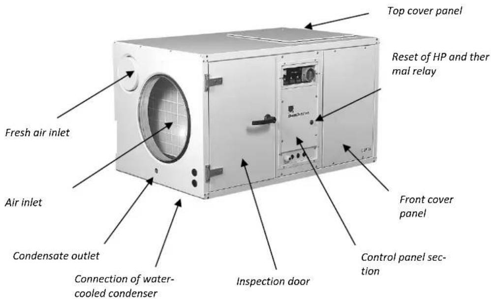
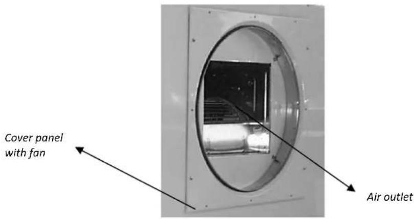
Functionality of the dehumidifier
The CDP 75 MK II, 125 MK II and 165 are working in accordance with the condensation principle.
The humid air is drawn into the unit by a fan.
In the evaporator the air is cooled and when its temperature has fallen to below the dew point, the water vapour condenses into droplets which are led to a drain.
The dry cold air is then passed through the condenser where it is reheated.
As a result of the released evaporator heat and the working energy of the compressor being turned into heat energy, more heat is returned to the air than was previously extracted. This extra heat corresponds to an approximate increase in temperature of 5^ C.
The repeated circulation of air through the unit reduces the relative humidity, giving very rapid but gentle drying.
Continued overleaf
Product and functional description, continued
| Fan | If a water heating coil is used, the fan will start when heat is switched on. The fan continues to run for 30 seconds after the heat has been switched off. On condition, however, that the water heating coil is connected to the control signal through terminal points 1 and 2.If the water heating coil is controlled externally and is not connected to the unit control, the fan will not automatically be switched on when the water heating coil is connected. The control of CDP 75 MK II/125 MK II/165 has an option for connecting an external ON/OFF switch for continuous fan operation - allowing the fan to be running independently of the dehumidification and/or heating requirements. The switch is connected to terminals 7 and 8 and the outlet for the switch is 12 V. The bridge between terminals 7 and 8 has to be removed first. |
| Compressor | The number of compressor startings is limited by a 6 minutes timer, which starts up when switching on the compressor. The timer must have come to an end before the compressor can be switched on again.The control system of the unit has a time delay of 75 seconds. This means that each time the unit has been switched off on the main switch or on the hygrostat, it will take 75 seconds before the compressor can be switched on again.This is a safety function protecting the compressor against overloading caused by too high pressure in the cooling circuit at the start-up. |
| LP/HP pressostat | The CDP 75 MK II, CDP 125 MK II and CDP 165 are fitted with a reset button of the HP pressostat on the inspection side |
| Thermal relay | The CDP 125 MK II(3x400V) and CDP 165(3x230V/3x400V) are additionally fitted with a reset button for the thermal relays. This protects the compressor. |
| Klixon | The compressors in CDP 75 MK II(1x230V) and CDP 125 MK II(1x230V) are protected by a Klixon and not by a thermal relay |
Display
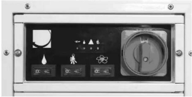
Display with LEDs and push buttons
The inspection side of the unit has a display panel with LEDs and push buttons.
natural_image
Control panel with icons for lighting, water, and scientific instruments (no readable text or symbols)LEDs
The LEDs in the display panel indicate various operation modes. An overview of the meaning of the LEDs is given below.
Illustration
The illustration shows the LEDs:
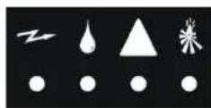
Meaning of the LEDs
The table gives an overview of the meaning of the LEDs: If the unit is switched off and restarted by connecting and disconnecting power, the LEDs will light up green in turn, before the operation mode is indicated on the display.
| LEDs | Description |
| Constantly green when power is connected to the unit | |
| Constantly green when the compressor is running and the unit is in dehumidification mode | |
| If the unit is supplied with a water heating coil, this LED will light up in green, when heat is connected |
Continued overleaf
Display, continued
Meaning of the LEDs, continued
| LEDs | Description |
| The constant green Lightning indicates that power is connected to the unit. The Drop and the Triangle are flashing on and off in green and red, respectively, to indicate that the condenser sensor has sensed a failure.If the low-pressure pressostat registers a too low pressure in the cooling circuit, caused by a too low temperature across the evaporator, the unit will be stopped until the required pressure has been re-established and the low-pressure pressostat then switches on the unit again.After resetting, the Triangle is switched off and the Drop continues to flash on and off. The Lightning is constantly green. | |
| When the Drop flashes on and off in green and the Lighting is constant green, this indicates that the unit is working but there has been a failure on the unit through the LP pressostat.The flashing Drop is switched off by turning the unit OFF and ON on the main switch. | |
| A constantly green Lightning indicates that power is on. The Drop and the Triangle LEDs flash on and off in green and lights up constantly in red, respectively, to indicate that the HP pressostat or the thermal relay has switched off the compressor and that the unit has been cut off.If the high-pressure pressostat has registered a too high pressure in the cooling circuit, caused by a too high temperature across the condenser, the compressor will be switched off and the unit stops. The thermal relay also switches off the compressor and stops the unit, if the temperature in the compressor gets too high. If the unit switches off again after having reset the HP pressostat and the thermal relay, the unit must be checked by a service engineer. (See section 7. Faults and how to remedy them). The flashing Drop is switched off by turning the unit OFF and ON on the main switch. |
Continued overleaf
Display, continued
| Push buttons | Push-buttons on the inspection side of the unit allows switching on and off dehumidifi-cation, heating coil and fan. | |
| Illustration | The illustration shows the push buttons:An overview of the meaning of the push but-tons is given below 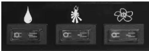 | |
| Positions of the push buttons | To switch on or off the functions, the setting of the push-buttons should be as follows:Resetting (B) O OFF (A) | |
| Functions of the push button | The table gives an overview of the push button functions: | |
| Push button | Description | |
| By means of the push-button with a Drop symbol, dehumidifica-tion can be switched off (A) or on (B) | ||
| By means of the push-button with a Fire symbol, the heating coil can be switched off (A) or on (B) | ||
| In position (A) the Fan is switched off and only runs if required - i.e. in accordance with the demand for dehumidification and/or heatingIn position (B) the fan run continuously - i.e. independent of the demand for dehumidification and/or heating | ||
Hygrostat and other control options
| Hygrostat | The control is prepared for connection of a hygrostat which is placed in the room to be dehumidified or in the supply air duct – (air inlet). Hygrostat is available as accessory. | |
| Connection of hygrostat | Please follow this procedure to connect a hygrostat. The outlet for the hygrostat is 12 V. | |
| Step | Action | |
| 1 | The hygrostat is connected to the terminals 3 and 4 after having taken away the bridge | |
| Room thermostat | The control is prepared for connection of a room thermostat which is placed in the room to be dehumidified or in the supply air duct – (air inlet). Room thermostat is available as accessory. | |
| Connection of room thermostat | Please follow this procedure to connect a room thermostat. The outlet for the room thermostat is 12 V. | |
| Step | Action | |
| 1 | The thermostat is connected to the terminals 5 and 6 after having taken away the bridge | |
Continued overleaf
Hygrostat and other control options, continued
Defrosting
If the CDP 75 MK II/125 MK II/165 are used in the temperature range between 15 and 20°C the evaporator coil should be protected by a sensor.
When the defrosting sensor registers a temperature below 5^ C, the control interprets this as ice building up on the evaporator coil and lets the unit run for another 30 minutes. Then the compressor stops and the fan leads the room air over the evaporator coil until the defrosting sensor registers that the temperature has reached 5^ C.
This defrosting process is called passive, demands-related defrosting, as it only takes place when needed.
The defrosting sensor is supplied on demand as an extra accessory. A mounting instruction follows the defrosting sensor.
Connection of defrosting sensor
Please follow this procedure to connect a defrosting sensor:
| Step | Action |
| 1 | The defrosting sensor is fixed in points 15 and 16 on the PCB terminal |
| 2 | DIP Switches 3 and 6 are set on ON |
| 3 | The sensor is placed in the sensor pocket of the evaporator coil |
Mounting and installation instructions
| Introduction | This section contains all necessary information for correct mounting of the dehumidifier.The electrical installation is described at the end of this section. | |
| Placing of CDP 75 MK II/125/165 | CDP 75 MK II, 125 MK II and 165 can be placed in one of the following ways: | |
| Placing | Comments | |
| Floor | The dehumidifier can be placed directly on the floor.Make sure that there is enough place for the drain outlet and the water trap. | |
| Footstands | The dehumidifier can be placed on shock absorbing footstands.The footstands are available as options on request. | |
| Suspension brackets | The footstands are available as options on request.When mounting the units onto a wall we recommend oscillation dampers to be fitted between the unit and the suspension brackets.The suspension brackets are available as options on request. | |
| Important | When placing the dehumidifier, unimpeded access to the inspection door should be ensuredWhen the unit has been mounted the handles are to be fixed to the inspection door | |
| Condensate outlet | The condensate outlet is located on the air inlet side. The dehumidifier is delivered with a 0,5 m water hose which is fixed to the 3/4" screw connector using the clip delivered with the hose. The water hose is led to a drain. | |
| Important | The hose from the unit to the external drainage must have a fall of at least 2%The drainage pipe has to be fitted with a water trap to prevent false air from getting in through the pipeAs an alternative a condensate pump can be fitted at the water outlet to pump the water to a drain | |
Continued overleaf
Mounting and installation instructions, continued
Air outlet through the top
Dependent on the design of the plant room, it is possible to blow the dry air out through the top of the unit. In that case the fan must be moved from the end to the top. It is done as follows:
| Step | Action |
| 1 | Remove the fan cable and loosen it from the terminals 7/8 in the control panel |
| 2 | Remove the cover panel with the fan fixed to it |
| 3 | Remove the top cover panel |
| 4 | Refit the cover panel with the fan to the top of the unit |
| 5 | Refit the top cover panel to the front of the unit |
| 6 | Connect the fan cable to the terminal 7 / 8 in the control panel |
Changing the inspection side
The inspection side of the unit can be changed to the opposite side. It is done as follows:
| Step | Action |
| 1 | Remove the rear cover panel |
| 2 | Remove the inspection door and the cover panel on front of the unit |
| 3 | Remove the middle control panel section and move it through the unit to the rear side |
| 4 | Remount the inspection door and the cover panel on the rear of the unit |
| 5 | Remount the cover panels on front of the unit |
Duct connection
The inlet and outlet ducts and any inlet and outlet grilles, must be dimensioned such that external pressure losses never exceed the values mentioned in the table below. If pressure losses are higher there is a danger of the unit cutting out via the high-pressure pressostat due to too little air passing over the condenser.
| CDP 75 MK II | CDP 125 MK II | CDP 165 | |
| Pa | 140 | 230 | 240 |
Continued overleaf
Mounting and installation instructions, continued
| Fresh air duct connection | On the air inlet side is an opening for connection of a fresh air duct. The opening is covered by a cover which has to be removed before connecting the fresh air duct. If a fresh air duct is connected, we recommend that a fan is mounted for drawing out the extra air in order to maintain a comfortable under pressure in the room and to avoid moist and chlorine-containing vapours diffusing through the walls.An external fan for removal of the extra amount of inlet air may be connected to terminal points 7 and 8 on the PCB together with the fresh air damper. The external fan will then start along with the fresh air damper. Maximum load on points 7 and 8 is 6A. | |||
| Maximum quantity of fresh air | The max. quantity of fresh air should not exceed the values mentioned in the table below.Too much fresh air, particularly in winter, could lead to ice formation on the evaporator and cut-out by the low-pressure pressostat. | |||
| CDP 75 MK II | CDP 125 MK II | CDP 165 | ||
| m^3/h | 225 | 375 | 540 | |
| Water heating coils | The CDP 75 MK II, 125 MK II and 165 can be fitted with water heating coils.The heating coil is designed for installation in the air outlet duct. The heating coil has duct connection spigots allowing direct fixing to the connections of the units.The technical specifications for the water heating coils are given in the table on page 125. | |||
| Connection of water heating coils | The control signal for control of the heating coil takes place through the terminals 1 and 2 and the outlet is 230 V/1A.The control is prepared for connecting a room thermostat to the terminals 5 and 6. The outlet of the thermostat is 12 V. The bridge between terminal 5 and 6 has to be removed before connecting the thermostat.If the control signal is used for control of the water heating coil and a connected room thermostat, the water heating coil will always be cut out when the power to the unit is turned off. When the water heating coil is connected as described above, it may be connected and disconnected by the push button with the fire symbol .(See section 4.3 Push button indications). | |||
| Water-cooled condenser | To lead away any excess heat from the unit, a water-cooled condenser may be fitted allowing transfer of the excess heat to the pool water instead of the room air.CDP 75 MK II, 125 MK II and 165 with water-cooled condenser are supplied with copper coupling pipes (Ø15 mm). The coupling pipes can be coupled together with PEX pipes by means of clamping ring fittings in cases where copper pipes are not required.The technical specifications for the water-cooled condenser are shown in the table on page 128. | |||
Continued overleaf
Mounting and installation instructions, continued
| Connection of water-cooled condenser | The condenser is normally activated by a temperature controlled pool water pump, which starts up automatically above a specified room temperature and pumps pool water through the condenser.The inflow is connected with the connector marked "IN" and the outflow with the connector marked "OUT". | |
| Connection of power supply | Power is connected to the unit in accordance with the name plate. Please refer to the wiring diagrams on page 141.Important! All electrical connections must be made in accordance with local power supply company regulations! | |
| Water quality | All electrical connections must be made in accordance with local power supply company regulations. | |
| With addition of chemicals | The following guidance values are applicable to swimming pools with the addition of chemicals: | |
| Chemicals ppm | ||
| Free chlorine content | 1,0-2,0 | |
| Combined chlorine content | Max. 1/3 of free chlorine content | |
| pH | 7,2-7,6 | |
| Total alkalinity | 80-150 | |
| Calcium hardness | 250-450 | |
| Total dissolved solids | < 2000 | |
| Sulphates | < 360 | |
| Self-production of chlorine | The following guidance values are applicable to swimming pools with self-production of chlorine: | |
| Chemicals ppm | ||
| Salt (NaCl) | 2700-3400 | |
| Total dissolved solids | < 5500 | |
| pH | 7,2-7,6 | |
| Total alkalinity | 80-150 | |
| Calcium hardness | 250-450 | |
| Sulphates | < 360 | |
| Langelier Saturation index | It is advisable to use the Langelier Saturation index to ensure that the combination of the different water parameters is acceptable.Contact Dantherm A/S if necessary. | |
Service guide
| Introduction | The dehumidifier requires very little attention for trouble free running. All the necessary safety and control functions have been built in. The fan motor(s) and the compressor have permanent lubrication and require no particular maintenance. | |
| Monthly service | Once a month the inlet air filter should be inspected and if necessary cleaned. Drip tray and drain must be cleaned so the water can run out without obstruction.Please follow this procedure to perform the monthly service: | |
| Step | Action | |
| 1 | Open the inspection door | |
| 2 | Take out the filter frame and remove the filter | |
| 3 | Clean the filter in luke-warm soapy water, or if only slightly soiled, with a vacuum-cleaner | |
| 4 | Replace the filter in its frame which can then be pushed back into the unit | |
| Annual service | Once a year the interior of the unit should be checked for cleanliness. Please follow this procedure to perform the annual service: | |
| Step | Action | |
| 1 | Open the inspection door and remove the front cover panel | |
| 2 | If the unit is dirty, it may be cleaned with a vacuum cleanerImportant: Especially the condenser and the fan rotor in particular should be thoroughly vacuum-cleaned | |
| 3 | If the lamella evaporator is badly soiled, it may be washed in lukewarm soapy water | |
| Service on components | In most cases the components are accessible for service after having removed the inspection door and the cover panels. Otherwise draw out the entire bridge/rail onto which the components are fixed.Important: Only qualified service technicians may carry out service on the components. Service on components is done as follows: | |
| Step | Action | |
| 1 | Switch off the unit on the main switch | |
| 2 | Open the inspection door and remove the front cover panel | |
| 3 | Remove the section in the middle with the control panel | |
| 4 | Undo the screws along the bridge/rail | |
| 5 | Pull out the bridge/rail.Important: If the bridge/rail has to be pulled entirely out of the unit, also the fan wires must be disconnected. | |
Fault finding guide
Important!
If the dehumidifier is not functioning correctly, shut it down immediately!
Fault finding
Use this table to localize and solve a possible problem or fault:
| Fault | Solution |
| The dehumidifier does not workNo light in the LEDs on the display | Check the external fusesCheck the power supply to the unit |
| The dehumidifier does not workThe triangle lights up constantly in red | Reset pressostat and thermal relayIf the dehumidifier does not work after several resettings of HP pressostat and thermal relay:Check that the room temperature is between 20 and 38°CCheck that the fan is runningCheck that the inlet and outlet air duct are free from obstruction and whether the filter is clean |
| The compressor does not workThe lighting on the display is light up in green | Check the room or duct hygrostat by setting it to a low relative humidity (10–20%)If the unit still does not start, check the room or duct hygrostat for defects. |
More help
If you cannot find the reason for the fault, switch off the unit immediately in order to prevent further damage. Contact a service technician or a Dantherm representative.
Technical information
Data
Technical data:
| Model | - | CDP 75 MK II | CDP 125 MK II | CDP 165 |
| Working area, humidity | %RF | 40–100 | 40–100 | 40–100 |
| Working area, temperature | °C | 20–38 | 20–38 | 20–38 |
| Air volume | m ^3 /h | 1500 | 2500 | 3600 |
| Max. external pressure | Pa | 140 | 230 | 240 |
| Power supply | V/Hz | 1 × 230/50 | 1 × 230/503 × 400/50 | 3 × 230/503 × 400/50 |
| Max. power consumption | kW | 2,0 | 2,8*/3,2** | 4,3 |
| Max. ampere consumption | A | 9,5 | 12,9* / 7,6** | 20,2 / 11,5** |
| LRA | A | - | 61 | - |
| Refrigerant | - | R407C | R407C | R407C |
| Quantity of refrigerant | kg | 2,1 | 5,2 | 6,8 |
| GWP (Global Warming Potential) | - | 1653 | ||
| Sound level(1 m away from unit) | dB(A) | 58 | 60 | 63 |
| Weight | kg | 130 | 160 | 190 |
| Dimensions, H × L × W | mm | 650x1155x725 | 850x1300x900 | 975x1400x1010 |
* Version 1x230V / ** Version 3x230V / 3x400V
Service agreement
| Introduction | The unit includes mechanical and electrical parts and the unit is often placed in a rough environment where the components are exposed to different climate conditions. Therefore the unit will need preventative maintenance on a regular basis. | ||
| Hotline | The After Sales Support Department of Dantherm A/S is ready to help you in case of a problem.To be able to offer quick and efficient help, please have the following information ready when contacting Dantherm A/S:NamePhone no.Site/location (unit)CompanyEmailSerial No/order No.CountryType (unit)Description of the problemContact Dantherm A/S, ask for the After Sales Support department and help will be provided as soon as possible:Phone: +45 96 14 37 00Fax: +45 96 14 38 00Email: info@dantherm.com | ||
| Preventive maintenance | Dantherm A/S offers to do the preventive maintenance on the units so that they at all times will operate according to factory standards. | ||
| Corrective and emergency repair | In case of malfunctions of the product Dantherm A/S offers to do emergency repair on the climate units. Agreements will be made with the customer on response time and price. | ||
| Setup | Dantherm A/S has established a network of service partners to do the preventative maintenance. The partner is trained and certified on the actual climate units. The partner will also carry an adequate number of spare parts – so that any repairs can be made during the same visit.The agreement will be made with Dantherm A/S – and the overall responsibility for the agreement will be Dantherm A/S’s. | ||
| Further information | For further information about spare parts, please contact:Dantherm A/SPhone: +45 9614 4700Webshop: shop.dantherm.comEmail: support@dantherm.com | ||
DE-Introduktion
Überblick
Warnung
natural_image
Control panel with icons for lighting, water, and scientific instruments (no readable text or symbols)Lichtdioden
natural_image
Control panel with icons for water drop, flame, and atom switch (no readable text or symbols)Diodes
natural_image
Control panel with icons for lighting, water, and fan (no readable text or symbols)Светоиндикаторы
natural_image
Front panel of an industrial control panel with icons for lighting, ventilation, and operation buttons (no readable text or symbols)Spie
natural_image
Control panel with icons for lighting, water, and fan (no readable text or symbols)Lysdioder
natural_image
Three black control panels with white line drawings of icons: water droplet, flower, and flower (no text or symbols)Tryckknapparnas positioner
- Site/placering (aggregat)
- Företag
Webshop: shop.dantherm.com
E-post: infose@dantherm.com
Service
Data på vandvarmefladerne / Data for water heating coils / Daten des Heizregisters / Données de la batterie eau chaude / Технические характеристики калориферов горячей воды / Dati tecnici della batteria ad acqua calda/ Data för vattenvärmebatterierna
| A | B | C | D | E | F | G | H | Kg | |
| 400 | 410 | 55 | 240 | 430 | 580 | 650 | 695 | 400 | 28 |
| 500 | 410 | 55 | 352 | 655 | 705 | 775 | 820 | 500 | 34 |
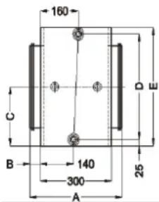
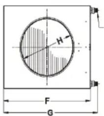
12'' / 34''
| CDP 75 MK II | 2RR | 2RR | 2RR | |
| Tilslutning/Connection/Anschluss/Raccordement eau chaude/ Тип соединения /Connessione/Anslutning | 12'' | 12'' | 12'' | |
| Kanal tilslutning/Duct connection/Kanalanschluss/Raccordement de gaine d'air/ Диаметр патрубка /Connessione condotto/Kanalanslutning | mm | 400 | 400 | 400 |
| Vandtemperatur/Water temperature/Heizwas-sertemperatur/Température de l'eau/ Температура воды на входе/выходе /Temperatura acqua/Vatten-temperatur | °C | 82/71 | 80/60 | 70/35 |
| Luftmængde/Air volume/Luftmenge/Débit d'air/Pасход воздуха /Portata Aria/Luftmängd | m3/h | 1500 | 1500 | 1500 |
| Udblæsningstemperatur/Outlet temperature/ Ausblas-temperatur/Température de soufflage de l'air/Температура воздуха на выходе /Temperatura di scarico/ Utloppstemperatur | °C | 56,78 | 51,67 | 39,56 |
| Kapacitet/Capacity/Heizleistung/Puissance de chauffage/ Тепловая мощность /Potenza/Kapacitet | kW | 15,15 | 12,54 | 4,86 |
| Vandmængde/Water flow/Wassermenge/Débit d'eau chaude/ Расход воды /Portata Acqua/Vattenmängd | l/h | 1152 | 504 | 108 |
| Tryktab, vand/Pressure drop, water/Widerstand, Wasser/Perte de charge sur l'eau/ Напор воды /Perdita di carico, acqua/ Tryckfall, vatten | kPa | 5,68 | 1,40 | 0,09 |
| Tryktab, luft/Pressure drop, air/Widerstand, Luft/Perte de charge sur l'air/ Потеря давления /Perdita di carico, aria/ Tryckfall, luft | Pa | 11,10 | 11,01 | 10,75 |
Fortsættes/continued overleaf/fortsetzt/Suite à la page suivante/Продолжение на след. стр./
The technical specifications of the water heating coils are based on a room temperature of 27^ C.
* Running conditions : LP 10 °C, HP 40 °C, water temperature 28 °C
* Betriebszustand: LP 10 °C, HP 40 °C, Wassertemperatur 28 °C
* Conditions de service: BP 10 °C, HP 40 °C, température d'eau 28 °C
flowchart
graph TD
    A["Feed Inlet"] --> B["Reactor"]
    B --> C["Valve ①"]
    C --> D["Reactor Unit ②"]
    D --> E["Pump"]
    E --> F["Reactor Unit ③"]
    F --> G["Reactor Unit ④"]
    G --> H["Reactor Unit ⑤"]
    H --> I["Reactor Unit ⑥"]
    I --> J["Reactor Unit ⑦"]
    J --> K["Reactor Unit ⑧"]
    K --> L["Reactor Unit ⑨"]
    L --> M["Reactor Unit ⑩"]
    M --> N["Reactor Unit ⑪"]
    N --> O["Reactor Unit ⑫"]
| Nr./No. | DA | EN | DE |
| 1 | Kompressor | Compressor | Kompressor |
| 2 | HP/LP pressostat | HP/LP pressostat | HP/LP pressostat |
| 3 | Luftkølet kondensator | Air-cooled condenser | Luftgekühlter Verflüssiger |
| 4 | Væskebeholder | Receiver | Receiver |
| 5 | Tørrefilter | Filter drier | Trockenfilter |
| 6 | Skueglas | Sight glass | Schauglas |
| 7 | Termo ekspansionsventil | Thermostatic expansion valve | Thermostatisches Expansionsventil |
| 8 | Fordamper | Evaporator | Verdampfer |
| 9 | Suge akkumulator | Suction accumulator | Flüssigkeitsabscheider |
| 10 | Magnetventil | Solenoid valve | Magnetventil |
Fortsættes/continued overleaf/fortsetzt/Suite à la page suivante/Продолжение на след. стр./
continua alla pagina seguente
CDP 125 MK II Kølekredsløb/Cooling Circuit/Kältekreislauf/Circuit frigorifique/Xолодильный контур/ Circuito frigorifero, /Köldmediekretslopp
| Nr./No. | FR | RU | IT |
| 1 | Compresseur | Компрессор | Compressore |
| 2 | Pressostat HP/BP | Реле высокого и низкого давления | Pressostato HP/LP |
| 3 | Condenseur à air | Водоохлаждаемый конденсатор | Condensatore raffred- dato ad aria |
| 4 | Bouteille liquide | Ресивер | Sebatoio |
| 5 | Déshydrateur | Фильтр-осушитель | Filtro a secco |
| 6 | Voyant liquide | Смотровое стекло | Oblò d'ispezione |
| 7 | Détendeur thermostati-que | Термо-расширительный вентиль | Valvola d'espansione termostatica |
| 8 | Évaporateur | Испаритель | Evaporatore |
| 9 | Accumulateur d'aspira-tion | аккумулятор всасывания | Aspirazione accumula- tore |
| 10 | Électrovanne | Электромагнитный клапан | Valvola solenoide |
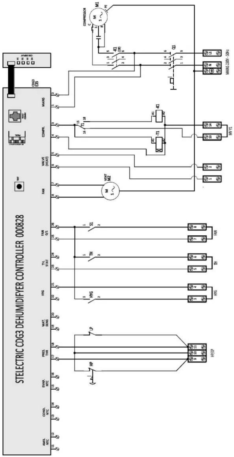
CDP 75 MK II - 1 x 230 V/50 Hz
CDP 75 MK II - 1 x 230 B/50 Гц
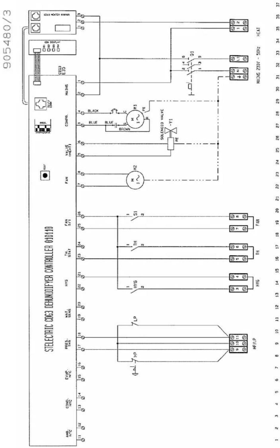
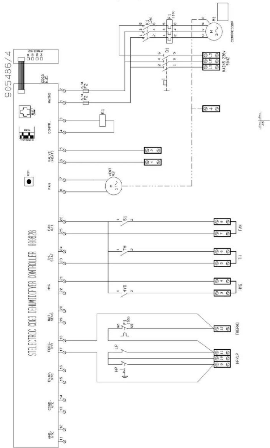
CDP 125 MK II Eldiagram/Wiring diagram/Schaltplan/Schéma électrique, Схема соединений/Schema elettrico, /Elschema
Diagram
Схема
CDP 125 MK II - 1 x 230 V/50 Hz
CDP 125 MK II - 1 x 230 B/50 Гц
CDP 125 MK II & CDP 165 - 3 x 230 V/50 Hz
CDP 125 MK II & CDP 165 - 3 x 230 V/50 Гц
Ordforklaring/Legend/Legende/Légende/Legenda/Legenda/Ord-förklaring
| Pos. Поз. | DA Beskrivelse | SE Beskrivning | EN Designation | DE Beschreibung | FR Désignation | RU Обозначение | IT Descrizione |
| HYG | Trykknap (dråbe) på inspektionssiden | Tryckknapp (droppe) på inspektionssidan | Pushbutton (drop) on inspection side | Druckknopf (Tropfen) auf der Inspektionsseite | Bouton- poussoir (goutte) sur coté d'inspection | Кнопка "капля" на инспекционной панели | Interruttore (Goccia) lato ispezione |
| TH | Trykknap (bål) på inspektionssiden | Tryckknapp (brasa) på inspektionsidan | Pushbutton (fire) on inspection side | Druckknopf (Flamme) auf der Inspektionsseite | Bouton- poussoir (feu) sur coté d'inspection | Кнопка "огонь" на инспекционной панели | Interruttore (fuoco) lato ispezione |
| S1 | Trykknap (ventilation) på inspektionssiden | Tryckknapp (ventilation) på inspektionsidan | Pushbutton (ventilation) on inspection side | Druckknopf (Ventilation) auf der Inspektionsseite | Bouton- poussoir (ventilation) sur coté d'inspection | Кнопка "вентиляция" на инспекционной панели | Interruttore (ventilazione) lato ispezi-one |
| M2 | Ventilatormotor | Fläktmotor | Fan motor | Ventilator-motor | Moteur de ventilateur | Электродвигатель вентилятора | Motore del ventilatore |
| Y1 | Magnetventil | Magnetventil | Solenoid valve | Magnetventil | Electrovanne | Электромагнитный клапан | Valvola sole-noide |
| K1 | Kontaktor for kompressor | Kontaktor för kompressor | Contactor for compressor | Kontaktor für Kompressor | Contacteur du compresseur | Контактор компрессора | Contattore per compressore |
| F2 | Sikring | Säkring | Fuse | Sicherung | Fusible | Предохранитель | Fusibile |
| Q1 | Hovedafbryder | Huvudström-brytare | Main switch | Hauptschalter | Sectionneur général | Основной выключатель | Interruttore principale |
| F1 | Termorelæ for kompressor | Termiskt relä för kompressor | Thermal relay for compressor | Thermorelais für Kompressor | Relais thermique du compresseur | Термореле компрессора | Relè termico per compressore |
| M1 | Kompressor-motor | Kompressor motor | Compressor motor | Kompressor-motor | Moteur de compresseur | Электродвигатель компрессора | Motore del compressore |
CDP 75 MK II Reservedele/Spare parts/Ersatzteile/Pièces de rechange/Запасные части/Parti di ricambio, /Reservedelar
Illustration CDP 75 MK II - 1 × 230 V/50 Hz
962442
Fortsættes/continued overleaf/fortsetzt/Suite à la page suivante/Продолжение на след. стр./continua alla pagina seguente
CDP 75 MK II Reservedele/Spare parts/Ersatzteile/Pièces de rechange/Запасные части/Parti di ricambio, /Reservedelar

| Pos. | DanthermNr./No. | DABeskrivelse | ENDesignation |
| 1 | 293600 | Topplade | Top cover panel |
| 2 | 175357 | Blændeplade, kpl. | Blind cover, cpl. |
| 3 | 293601 | Gavl højre | Cover panel right |
| 4 | 175375 | Ventilator holder, kpl. | Fan bracket, cpl. |
| 5 | 530150 | Ventilator | Fan |
| 6 | 069219 | ||
| 7 | 069204 | ||
| 8 | 175289 | Dækplade bag kpl. | Cover panel, rear, cpl. |
| 9 | 175296 | Filter, kpl. | Filter, cpl. |
| 9a | 069216 | Filterrist, indre | Filter grille, internal |
| 9b | 088027 | Filter | Filter |
| 9c | 069217 | Filterrist, ydre | Filter grille, external |
| 10 | 293602 | Gavl, venstre | Cover panel left |
| 10a | 068894 | Indløbsstuds | Inlet spigot |
| 11 | 524750 | Membrantylle | Diaphragm bush |
| 12 | 069203 | ||
| 13 | 600027 | Fordamperflade | Evaporator |
| 14 | 600026 | Kondensatorflade | Condenser |
| 15 | 069197 | ||
| 16 | 069198 | Styr for kondensator flade | Guide for condenser coil |
| 17 | 091324 | Kompressor, kpl. | Compressor, cpl. |
| 17a | 091325 | Kompressor | Compressor |
| 17b | 091326 | Tilbehør til kompressor:SvingningsdæmperBøsning for kompressorFlange møtrikDækselPakning for dækselGummiskive til kompressor | Accessories for compressor :Vibration damperBushing for compressorHex NutCapSealRubber disc for compressor |
| 18 | 607231 | Tørrefilter | Dry filter |
| 19 | 607630 | Skueglas | Inspection glass |
| 20 | 603911 | Termoventil | Thermo-valve |
| 21 | 602740 | Receiver | Receiver |
| 22 | 175333 | Vandkølet kondensator kpl. | Water-cooled condenser, cpl. |
| 23 | 0659505 | ||
| 24 | 032297 | Patronpressostat | Cartridge pressostat |
| 25 | 606711 | Patronpressostat | Cartridge pressostat |
Fortsættes/continued overleaf/fortsetzt/Suite à la page suivante/Продолжение на след. стр./
continua alla pagina seguente
CDP 75 MK II Reservedele/Spare parts/Ersatzteile/Pièces de rechange/Запасные части/Parti di ricambio, /ReservedelarReservedelar
| Pos. | DanthermNr./No. | DABeskrivelse | ENDesignation |
| 26 | 175283 | Drypbakke | Condensate tray |
| 27 | 428100 | Slange, 1/2" | Armoured hose, 1/2" |
| 28 | 175297 | ||
| 29 | 293603 | Bundplade | Bottom cover panel |
| 30 | 175293 | Dækplade, venstre | Cover panel, left side |
| 31 | 541820 | Hængsel for dør | Hinge for door |
| 32 | 175361 | Håndtag | Handle |
| 33 | 069345 | ||
| 34 | 175295 | Dækplade | Cover panel |
| 35 | 293604 | Dækplade, højre | Cover panel, right side |
| 35a | 033928 | Skilt – CDP 75 MK II | Label – CDP 75 MK II |
| 36 | 091330 | El-kasse med skinner | Control panel with rails |
| 37 | 069208 | Manøvre panel | Operating panel |
| 38 | 517601 | Label for styrepanel | Label for operating panel |
| 39 | 521259 | Sikkerhedsafbryder | Safety switch |
| 40 | 517594 | Diodeprint | Diode print |
| 41 | 515081 | Vippeafbryder | Toggle switch |
| 42 | 517596 | Fladkabel til diodeprint | Flat cable for diode |
| 43 | 069206 | ||
| 44 | 091328 | Driftkondensator | Condenser |
| 45 | 517597 | Varmeprint for print | Heat print for print |
| 46 | 517593 | Printkort | PCB |
| 47 | 527034 | Kabelforskruning | Cable entry |
| 48 | 175362 | Klemmesamling | Terminal assembly |
| 49 | 069284 | Indtag for elkasse | Inlet for control panel |
| 50 | 527031 | Kabelforskruning | Cable entry |
| 51 | 524750 | Membrantylle | Diaphragm bush |
| 52 | 293605 | Inspektionspanel | Inspection panel |
| 52a | 033234 | Skilt – Dantherm logo | Label – Dantherm logo |
| 52b | 560620 | Gummitrykknap | Rubber push button |
| 53 | 175284 | El-kasse, kpl. | Control panel, cpl. |
| 54 | 605470 | Magnetventil | Solenoid valve |
| 55 | 605440 | Spole for magnetventil | Coil for solenoid valve |
| 56 | 604880 | Kontraventil | Non-return valve |
Fortsættes/continued overleaf/fortsetzt/Suite à la page suivante/Продолжение на след. стр./con-
tinua alla pagina seguente
CDP 75 MK II Reservedele/Spare parts/Ersatzteile/Pièces de rechange/Запасные части/Parti di ricambio, /Reservedelar
| Pos. | DanthermNr./No. | DEBeschreibung | FRDescription |
| 1 | 293600 | Deckplatte oben | Tôle en haut |
| 2 | 175357 | Blenddeckplatte, kpl. | Tôle dissimulée, cpl. |
| 3 | 293601 | Deckplatte rechts | Tôle droite |
| 4 | 175375 | Ventilatorhalter, kpl. | Support de ventilateur, cpl. |
| 5 | 530150 | Ventilator | Ventilateur |
| 6 | 069219 | ||
| 7 | 069204 | ||
| 8 | 175289 | Deckplatte hinten, kpl. | Tôle, derrière, cpl. |
| 9 | 175296 | Filter, kpl. | Filtre, cpl. |
| 9a | 069216 | Filtergitter, inwendig | Grille filtre, intérieure |
| 9b | 088027 | Filter | Filtre |
| 9c | 069217 | Filtergitter, auswendig | Grille filtre, extérieure |
| 10 | 293602 | Deckplatte links | Tôle gauche |
| 10a | 068894 | Einlassstutzen | Raccordement d'entrée |
| 11 | 524750 | Membrantülle | Douille diaphragne |
| 12 | 069203 | ||
| 13 | 600027 | Verdampfer | Evaporateur |
| 14 | 600026 | Verflüssiger | Condenseur |
| 15 | 069197 | ||
| 16 | 069198 | Steuer für Verflüssiger | Guide du condenseur |
| 17 | 091324 | Kompressor, kpl. | Compresseur, cpl. |
| 17a | 091325 | Kompressor | Compresseur |
| 17b | 091326 | Zubehör für Kompressor:SchwingungsdämpferBuchse für KompressorSechskantmutterDeckelDichtungGummischeibe für Kompressor | Accessoires p. compresseur :Amortisseur de vibrationsManchon p. CompresseurÉcrou hexagonalCouvertureJoint d'étanchéitéDisque en caoutchouc pour le compresseur |
| 18 | 607231 | Trockenfilter | Filtre sec |
| 19 | 607630 | Schauglas | Verre indicateur |
| 20 | 603911 | Thermoventil | Clapet thermostatique |
| 21 | 602740 | Receiver | Collecteur |
| 22 | 175333 | Wassergekühlter Verflüssiger, kpl. | Condenseur à eau, cpl. |
| 23 | 0659505 | ||
| 24 | 032297 | Patronenpressostat | Pressostat cartouche |
| 25 | 606711 | Patronenpressostat | Pressostat cartouche |
Fortsættes/continued overleaf/fortsetzt/Suite à la page suivante/Продолжение на след. стр./
continua alla pagina seguente
CDP 75 MK II Reservedele/Spare parts/Ersatzteile/Pièces de rechange/Запасные части/Parti di ricambio, /Reservedelar
| Pos. | DanthermNr./No. | DEBeschreibung | FRDescription |
| 26 | 175283 | Kondenswasserschale | Bac à eau condensée |
| 27 | 428100 | Wasserschlauch, 1/2" | Tuyau d'écoulement, 1/2" |
| 28 | 175297 | ||
| 29 | 293603 | Bodenplatte | Tôle de fond |
| 30 | 175293 | Deckplatte, links | Tôle, gauche |
| 31 | 541820 | Scharnier für Tür | Charnière p. porte |
| 32 | 175361 | Handgriff | Poignée |
| 33 | 069345 | ||
| 34 | 175295 | Deckplatte | Tôle |
| 35 | 293604 | Deckplatte, rechts | Tôle, droite |
| 35a | 033928 | Aufkleber - CDP 75 MK II | Etiquette - CDP 75 MK II |
| 36 | 091330 | Schaltschrank mit Schienen | Coffret de régulation avec rail |
| 37 | 069208 | Manövrierpaneel | Panneau de manœuvre |
| 38 | 517601 | Aufkleber für Manövrierpaneel | Étiquette pour panneau de manœuvre |
| 39 | 521259 | Sicherheitsschalter | Coupe-circuit de sécurité |
| 40 | 517594 | Diodenplatine | Platine de diode |
| 41 | 515081 | Kippschalter | Interrupteur basculant |
| 42 | 517596 | Flachkabel für Diodenplatine | Cable plat pour platine de diode |
| 43 | 069206 | ||
| 44 | 091328 | Betriebsverflüssiger | Condenseu |
| 45 | 517597 | Wärmeprint für Platine | Platine chauffage pour platine |
| 46 | 517593 | Platine | Platine électronique |
| 47 | 527034 | Kabelverschraubung | Entrée de cable |
| 48 | 175362 | Klemmensammlung | Assemblage des bornes |
| 49 | 069284 | Einlass für Schaltschrank | Entrée pour coffret de régulation |
| 50 | 527031 | Kabelverschraubung | Entrée de cable |
| 51 | 524750 | Membrantülle | Douille diaphragne |
| 52 | 293605 | Inspektionspaneel | Panneau d'inspection |
| 52a | 033234 | Aufkleber - Dantherm logo | Etiquette - logo Dantherm |
| 52b | 560620 | Gummidruckknopf | Bouton poussoir en caout-chouc |
| 53 | 175284 | El-kasse, kpl. | Panneau de commande cpl. |
| 54 | 605470 | Magnetventil | Vanne solénoïde |
| 55 | 605440 | Spule für Magnetventil | Bobine pour vanne solénoïde |
| 56 | 604880 | Rückschlagventil | Soupape de non-retour |
Fortsættes/continued overleaf/fortsetzt/Suite à la page suivante/Продолжение на след. стр./ continua alla pagina seguente
CDP 75 MK II Reservedele/Spare parts/Ersatzteile/Pièces de rechange/Запасные части/Parti di ricambio, /ReservedelarReservedelar
Illustration CDP 125 MK II - 3 × 400 V/50 Hz
Fortsættes/continued overleaf/fortsetzt/Suite à la page suivante/Продолжение на след. стр./
continua alla pagina seguente
Illustration CDP 125 MK II - 1 × 230 V/50 Hz
Fortsættes/continued overleaf/fortsetzt/Suite à la page suivante/Продолжение на след. стр./continua alla pagina seguente
CDP 125 MK II Reservedele/Spare parts/Ersatzteile/Pièces de rechange/Запасные части/Parti di ricambio/ Reservedelar/ Reservedelar
| Pos. | DanthermNr./No. | DABeskrivelse | ENDesignation |
| 1 | 293606 | Topplade | Top cover panel |
| 2 | 175357 | Blændeplade, kpl. | Blind cover, cpl. |
| 3 | 293607 | Gavl højre | Cover panel right |
| 4 | 175359 | Ventilator holder, kpl. | Fan bracket, cpl. |
| 5 | 531520 | Ventilator DDM9/9 | Fan DDM9/9 |
| 6 | 069326 | ||
| 7 | 069329 | ||
| 8 | 175305 | Dækplade bag kpl. | Cover panel, rear, cpl. |
| 9 | 293816 | Filter, kpl. | Filter, cpl. |
| 9a | 069317 | Filterrist, indre | Filter grille, internal |
| 9b | 088028 | Filter | Filter |
| 9c | 069318 | Filterrist, ydre | Filter grille, external |
| 10 | 293608 | Gavl, venstre | Cover panel left |
| 10a | 069346 | Endebund type EPF 160 male | Bottom plate |
| 11 | 524750 | Membrantylle DG11 | Diaphragm bush DG11 |
| 12 | 600020 | Fordamperflade | Evaporator |
| 13 | 600940 | Kondensatorflade | Condenser |
| 14 | 069349 | ||
| 15 | 069348 | ||
| 16 | 081869 | Kompressor SCI rotation | Kompressor SCI rotary |
| 16c | 081874 | Svingningsdæmper | Vibration damper |
| 17 | 602790 | Receiver 2,4 l afsp.ventil | Receiver 2,4 L |
| 18 | 607231 | Tørrefilter 3/8" | Dry filter 3/8" |
| 19 | 607630 | Skueglas SGN 10s, 014-0182 | Inspection glass SGN 10S |
| 20 | 603942 | Termoventil TEX 2-1.5 | Thermo-valve TEX 2-1,5 |
| 21 | 175347 | ||
| 22 | 175298 | Drypbakke svejst | Condensate tray |
| 23 | 428100 | Slange 1/2" armeret grøn | Armoured hose 1/2" |
| 24 | 293609 | Bundplade | Bottom cover panel |
| 25 | 175361 | Håndtag sæt til låge | Handle |
| 26 | 175308 | Dækplade venstre kpl. | Cover panel, left side |
| 27 | 541820 | Hængsel for isol. dør | Hinge for insulated door |
Fortsættes/continued overleaf/fortsetzt/Suite à la page suivante/Продолжение на след. стр./
CDP 165 - 3 × 400 V/50 Hz
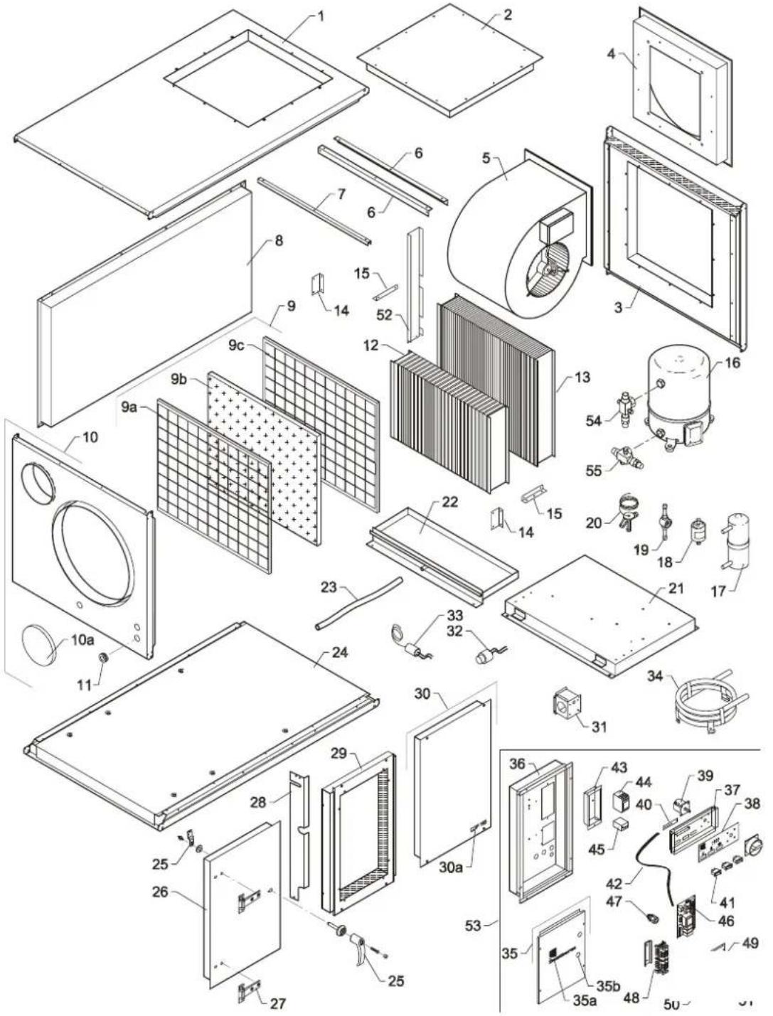
Fortsættes/continued overleaf/fortsetzt/Suite à la page suivante/Продолжение на след. стр./
continua alla pagina seguente
CDP 165 Reservedele/Spare parts/Ersatzteile/Pièces de rechange/ Запасные части/Parti di ricambio, /Reservedelar/ Reservedelar

| Pos. | DanthermNr./No. | DABeskrivelse | ENDesignation |
| 1 | 293612 | Topplade | Top cover panel |
| 2 | 175364 | Blændeplade, kpl. | Blind cover, cpl. |
| 3 | 293613 | Gavl højre | Cover panel right |
| 4 | 175365 | Ventilator holder, kpl. | Fan bracket, cpl. |
| 5 | 531700 | Ventilator DDM10/10 | Fan DDM10/10 |
| 6 | 069377 | ||
| 7 | 069382 | ||
| 8 | 175321 | Dækplade bag kpl. | Cover panel, rear, cpl. |
| 9 | 175344 | Filter, kpl. | Filter, cpl. |
| 9a | 069365 | Filterrist, indre RAL 9016 | Filter grille, internal RAL 9016 |
| 9b | 088029 | Filter | Filter |
| 9c | 069366 | Filterrist, ydre RAL 9016 | Filter grille, external RAL 9016 |
| 10 | 293614 | Gavl, venstre | Cover panel left |
| 10a | 069346 | Endebund | Bottom plate |
| 11 | 524750 | Membrantylle DG11 | Diaphragm bush DG11 |
| 12 | 600028 | Fordamperflade | Evaporator |
| 13 | 600029 | Kondensatorflade | Condenser |
| 14 | 069384 | ||
| 15 | 069348 | ||
| 16 | 602021 | Kompressor MTZ 36 400V | Compressor MTZ 36 400V |
| 17 | 602790 | Receiver 2,4 l | Receiver 2,4 L |
| 18 | 607231 | Tørrefilter 3/8" | Dry filter 3/8" |
| 19 | 607630 | Skueglas SGN 10s, 014-0182 | Inspection glass SGN 10S |
| 20 | 605112 | Termoventil TUBE 2-2.3 | Thermo-valve TUBE 2-2.3 |
| 21 | 175346 | ||
| 22 | 175314 | Drypbakke svejst | Condensate tray |
| 23 | 428100 | Slange 1/2" armeret grøn | Armoured hose 1/2" |
| 24 | 293615 | Bundplade | Bottom cover panel |
| 25 | 175361 | Håndtag sæt til låge | Handle |
| 26 | 175324 | Dækplade venstre kpl. | Cover panel, left side |
| 27 | 541820 | Hængsel for isol. dør | Hinge for insulated door |
| 28 | 069351 |
Fortsættes/continued overleaf/fortsetzt/Suite à la page suivante/Продолжение на след. стр./continua alla pagina seguente
CDP 165 Reservedele/Spare parts/Ersatzteile/Pièces de rechange/ Запасные части/Parti di ricambio, /Reservedelar/ Reservedelar
| Pos. | DanthermNr./No. | DABeskrivelse | ENDesignation |
| 29 | 175326 | ||
| 30 | 293616 | Dækplade højre | Cover panel, right side |
| 30a | 033930 | Skilt CDP 165, 15mm sort | Label CDP 165, 15 mm black |
| 31 | 069505 | ||
| 32 | 606730 | Patronpressostat | Cartridge pressostat |
| 33 | 606711 | Patronpressostat | Cartridge pressostat |
| 34 | 175333 | Vandkølet kondensator kpl. | Water-cooled condenser |
| 35 | 293617 | Inspektionspanel | Inspection panel |
| 35a | 033234 | Skilt Dantherm logo, 3 farver | Label Dantherm logo, 3 colo-urs |
| 35b | 560620 | Gummitrykknap sort | Rubber push button |
| 36 | 175348 | ||
| 37 | 069208 | Manøvre panel | Operating panel |
| 38 | 517601 | Label for styrepanel | Label for operating panel |
| 39 | 521259 | Sikkerhedsafbryder 3 polet | Safety switch |
| 40 | 517594 | Diodeprint | Diode print |
| 41 | 515081 | Vippeafbryder, sort, 1 pol | Toggle switch, black |
| 42 | 517596 | Fladkabel til CDP diodeprint | Flat cable for CDP diode print |
| 43 | 069210 | ||
| 44 | 510340 | Kontaktor CI 9 220/240V | Contactor CI 9 220/240 V |
| 45 | 511420 | Termorelæ TI 16C 6.0-9.2A | Thermal relay |
| 46 | 517593 | Printkort type CDG 3 | PCB type CDG3 |
| 47 | 527031 | Kabelforskruning PG 11 | Cable entry PG 11 |
| 48 | 175374 | Klemmesamling | Terminal assembly |
| 49 | 069284 | Indtag for elkasse | Inlet for control panel |
| 50 | 527031 | Kabelforskruning PG11 | Cable entry PG11 |
| 51 | 527030 | ||
| 52 | 069513 | ||
| 53 | 175315 | EI-kasse komplet | Control panel cpl. |
| 54 | 602230 | Ventil V06, rotalock 1" - 12 " | Valve V06, Rotalock 1"-1/2" |
| 55 | 602250 | Ventil V09, rotalock | Valve V09, Rotalock |
Fortsættes/continued overleaf/fortsetzt/Suite à la page suivante/Продолжение на след. стр./continua alla pagina seguente
CDP 165 Reservedele/Spare parts/Ersatzteile/Pièces de rechange/ Запасные части/Parti di ricambio, /Reservedelar/ Reservedelar
| Pos. | DanthermNr./No. | DEBeschreibung | FRDescription |
| 1 | 293612 | Deckplatte oben | Tôle en haut |
| 2 | 175364 | Blenddeckplatte, kpl. | Tôle dissimulée, cpl. |
| 3 | 293613 | Deckplatte rechts | Tôle droite |
| 4 | 175365 | Ventilatorhalter, kpl. | Support de ventilateur, cpl. |
| 5 | 531700 | Ventilator DDM10/10 | Ventilateur DDM10/10 |
| 6 | 069377 | ||
| 7 | 069382 | ||
| 8 | 175321 | Deckplatte hinten, kpl. | Tôle, derrière, cpl. |
| 9 | 175344 | Filter, kpl. | Filtre, cpl. |
| 9a | 069365 | Filtergitter, inwendig RAL 9016 | Grille filtre, intérieure RAL 9016 |
| 9b | 088029 | Filter | Filtre |
| 9c | 069366 | Filtergitter, auswendig RAL 9016 | Grille filtre, extérieure RAL 9016 |
| 10 | 293614 | Deckplatte links | Tôle gauche |
| 10a | 069346 | Bodenplatte | Tôle de fond |
| 11 | 524750 | Membrantülle DG11 | Douille diaphragne DG11 |
| 12 | 600028 | Verdampfer | Evaporateur |
| 13 | 600029 | Verflüssiger | Condenseur |
| 14 | 069384 | ||
| 15 | 069348 | ||
| 16 | 602021 | Kompressor MTZ 36 400V | Compresseur MTZ 36 400V |
| 17 | 602790 | Receiver 2,4 l | Receiver 2,4 L |
| 18 | 607231 | Trockenfilter 3/8" | Filtre sec 3/8" |
| 19 | 607630 | Schauglas SGN 10S | Verre indicateur SGN 10S |
| 20 | 605112 | Thermoventil TUBE 2-2.3 | Clapet thermique TUBE 2-2.3 |
| 21 | 175346 | ||
| 22 | 175314 | Kondenswasserschale | Kondenswasserschale |
| 23 | 428100 | Wasserschlauch 1/2", armiert | Tuyau d'écoulement 1⁄2", armé |
| 24 | 293615 | Bodendeckplatte | Tôle de fond |
| 25 | 175361 | Handgriff | Poignée |
| 26 | 175324 | Deckplatte, links | Tôle gauche |
| 27 | 541820 | Scharnier für isol. Tür | Charnière p. porte isolée |
| 28 | 069351 |
Fortsættes/continued overleaf/fortsetzt/Suite à la page suivante/Продолжение на след. стр./
continua alla pagina seguente
CDP 165 - 3 × 230 V/50 Hz
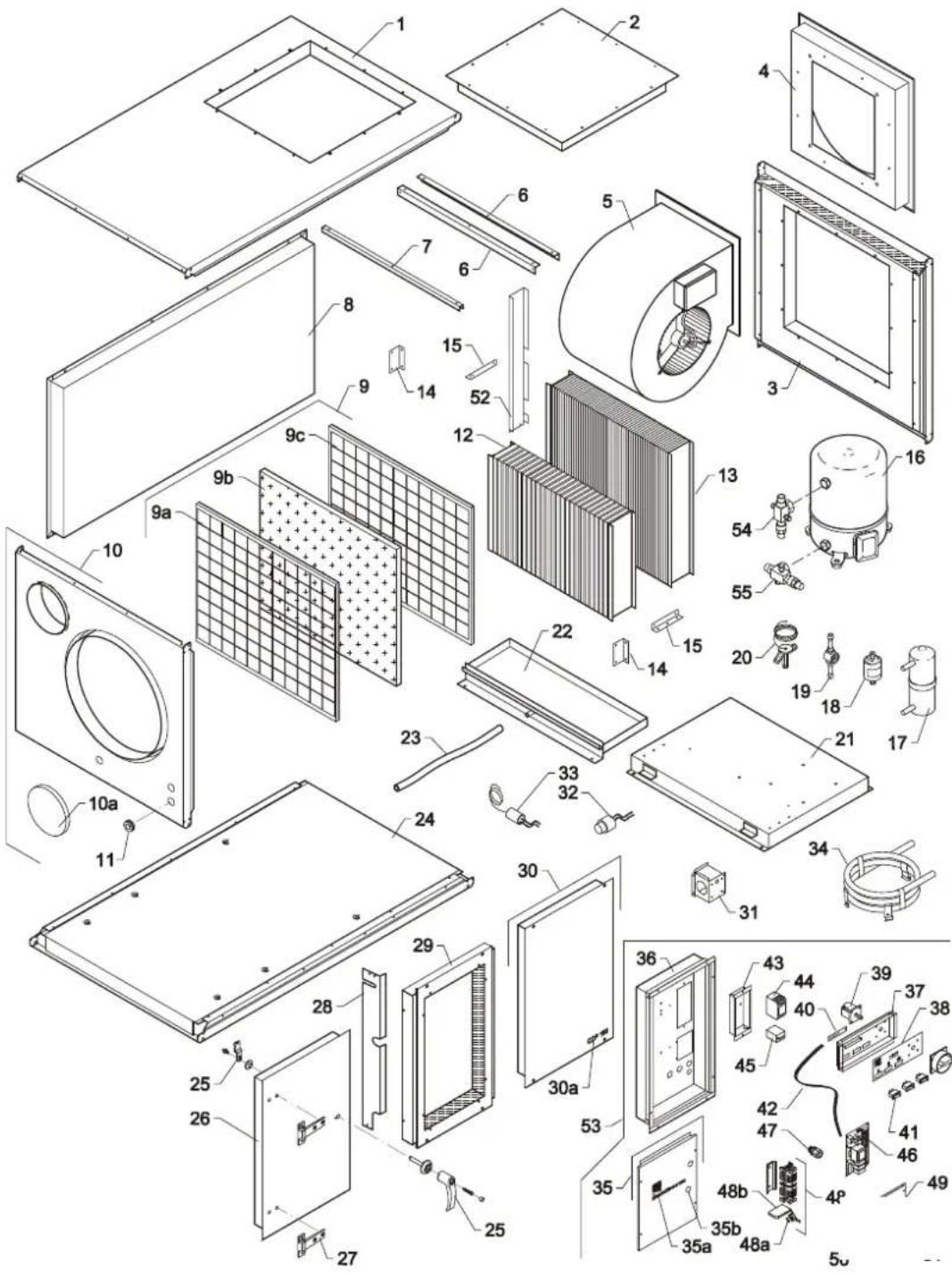
Fortsættes/continued overleaf/fortsetzt/Suite à la page suivante/Продолжение на след. стр./
continua alla pagina seguente
CDP 165 Reservedele/Spare parts/Ersatzteile/Pièces de rechange/Запасные части/Parti di ricambio /Reservedelar/ Reservedelar
| DA |
| SE |
| EN |
| Pos. | DanthermNr./No. | DABeskrivelse | SEBeskrivning | ENDesignation |
| 1 | 293612 | Topplade | Topplatta | Top cover panel |
| 2 | 175364 | Blændeplade, kpl. | Bländarplåt, Kpl | Blind cover, cpl. |
| 3 | 293613 | Gavl højre | Gavel höger | Cover panel right |
| 4 | 175365 | Ventilator holder, kpl. | Fläkthållare, kompl. | Fan bracket, cpl. |
| 5 | 531700 | Ventilator DDM10/10 | Fläkt DDM10/10 | Fan DDM10/10 |
| 6 | 069377 | |||
| 7 | 069382 | |||
| 8 | 175321 | Dækplade bag kpl. | Skyddsplåt bakom kpl. | Cover panel, rear, cpl. |
| 9 | 175344 | Filter, kpl. | Filter, Kpl | Filter, cpl. |
| 9a | 069365 | Filterrist, indre RAL 9016 | Filtergaller, inre RAL 9016 | Filter grille, internal RAL 9016 |
| 9b | 088029 | Filter | Filter | Filter |
| 9c | 069366 | Filterrist, ydre RAL 9016 | Filtergaller, yttre RAL 9016 | Filter grille, external RAL 9016 |
| 10 | 293614 | Gavl, venstre | Gavel, vänster | Cover panel left |
| 10a | 069346 | Endebund | Ändbotten | Bottom plate |
| 11 | 524750 | Membrantylle DG11 | Membrantylle DG11 | Diaphragm bush DG11 |
| 12 | 600028 | Fordamperflade | Förångarens yta | Evaporator |
| 13 | 600029 | Kondensatorflade | Kondensatorgivare | Condenser |
| 14 | 069384 | |||
| 15 | 069348 | |||
| 16 | 602023 | Kompressor MTZ 36 JG6V 3x230V | Kompressor MTZ 36 JG6V 3x230 V | Compressor MTZ 36 JG6V 3x230V |
| 17 | 602790 | Receiver 2,4 l | Receiver 2,4 l | Receiver 2,4 L |
| 18 | 607231 | Tørrefilter 3/8" | Torkfilter 3/8" | Dry filter 3/8" |
| 19 | 607630 | Skueglas SGN 10s, 014-0182 | Synglas SGN 10s, 014-0182 | Inspection glass SGN 10S |
| 20 | 605112 | Termoventil TUBE 2-2.3 | Värmeventil TUBE 2-2.3 | Thermo-valve TUBE 2-2.3 |
| 21 | 175346 | |||
| 22 | 175314 | Drypbakke svejst | Droppbricka svetsad | Condensate tray |
| 23 | 428100 | Slange 1/2" armeret grøn | Slang 1/2" armerad grön | Armoured hose 1/2" |
| 24 | 293615 | Bundplade | Bottenplatta | Bottom cover panel |
| 25 | 175361 | Håndtag sæt til låge | Handtagssats för lucka | Handle |
| 26 | 175324 | Dækplade venstre kpl. | Skyddsplåt vänster kpl. | Cover panel, left side |
| 27 | 541820 | Hængsel for isol. dør | Gångjärn för isol. dörr | Hinge for insulated door |
| 28 | 069351 | |||
| 29 | 175326 |
Fortsættes/continued overleaf/fortsetzt/Suite à la page suivante/Продолжение на след. стр./continua alla pagina seguente
CDP 165 Reservedele/Spare parts/Ersatzteile/Pièces de rechange/Запасные части/Parti di ricambio /Reservedelar/ Reservedelar
| Pos. | DanthermNr./No. | DABeskrivelse | SEDesignation | ENDesignation |
| 30 | 293616 | Dækplade højre | Skyddsplåt höger | Cover panel, right side |
| 30a | 033930 | Skilt CDP 165, 15mm sort | Skylt CDP 165, 15 mm svart | Label CDP 165, 15 mm black |
| 31 | 069505 | |||
| 32 | 606730 | Patronpressostat | Patronpressostat | Cartridge pressostat |
| 33 | 606711 | Patronpressostat | Patronpressostat | Cartridge pressostat |
| 34 | 175333 | Vandkølet kondensator kpl. | Vattenkyld kondensor kompl. | Water-cooled condenser |
| 35 | 293617 | Inspektionspanel | Inspektionspanel | Inspection panel |
| 35a | 033234 | Skilt Dantherm logo, 3 far-ver | Skylt Dantherm-logga, 3 färger | Label Dantherm logo, 3 co-lours |
| 35b | 560620 | Gummitrykknap sort | Gummitryckknapp svart | Rubber push button |
| 36 | 175348 | |||
| 37 | 069208 | Manøvre panel | Manöverpanel | Operating panel |
| 38 | 517601 | Label for styrepanel | Kontrollpaneldekal | Label for operating panel |
| 39 | 521274 | Sikkerhedsafbryder 3 polet | Säkerhetsbrytare 3-polig | Safety switch |
| 40 | 517594 | Diodeprint | Diodkretskort | Diode print |
| 41 | 515081 | Vippeafbryder, sort, 1 pol | Vippströmbrytare, svart, 1 pol | Toggle switch, black |
| 42 | 517596 | Fladkabel til CDP diodeprint | Plattkabel till CDP-di-odkretskort | Flat cable for CDP diode print |
| 43 | 069210 | |||
| 44 | 510380 | Kontaktor CI 16 220/240V | Kontaktor CI 16 220/240 V | Contactor CI 16 220/240 V |
| 45 | 511440 | Termorelæ TI 16C 6.0-9.2A | Värmerelä TI 16C 6.0-9.2A | Thermal relay |
| 46 | 517593 | Printkort type CDG 3 | Kretskort typ CDG 3 | PCB type CDG3 |
| 47 | 527031 | Kabelforskruning PG 11 | Kabelförskruvning PG 11 | Cable entry PG 11 |
| 48 | 175393 | Klemmesamling | Klämmmontering | Terminal assembly |
| 48a | 516000 | Sikring træg T6 3A/250 VT | Säkring trög T6 3A/250 VT | Slow-blow fuse 3A/250 VT |
| 48b | 516010 | Sikringssokkel | Säkringssockel | Fuse socket |
| 49 | 069284 | Indtag for elkasse | Intag ellåda | Inlet for control panel |
| 50 | 527031 | Kabelforskruning PG11 | Kabelförskruvning PG11 | Cable entry PG11 |
| 51 | 527030 | Kabelforskruning PG16 | Kabelförskruvning PG16 | Cable entry PG 16 |
| 52 | 069513 | |||
| 53 | 175386 | El-kasse komplet | Elskåp komplett | Control panel cpl. |
| 54 | 602230 | Ventil V06, rotalock 1" -1⁄2" | Ventil V06, rotalock 1"-1⁄2" | Valve V06, Rotalock 1"-1/2" |
| 55 | 602250 | Ventil V09, rotalock | Ventil V09, rotalock | Valve V09, Rotalock |
Fortsættes/continued overleaf/fortsetzt/Suite à la page suivante/Продолжение на след. стр./continua alla pagina seguente
CDP 165 Reservedele/Spare parts/Ersatzteile/Pièces de rechange/Запасные части/Parti di ricambio /Reservedelar
| Pos. | DanthermNr./No. | DEBeschreibung | FRDescription |
| 1 | 293612 | Deckplatte oben | Tôle en haut |
| 2 | 175364 | Blenddeckplatte, kpl. | Tôle dissimulée, cpl. |
| 3 | 293613 | Deckplatte rechts | Tôle droite |
| 4 | 175365 | Ventilatorhalter, kpl. | Support de ventilateur, cpl. |
| 5 | 531700 | Ventilator DDM10/10 | Ventilateur DDM10/10 |
| 6 | 069377 | ||
| 7 | 069382 | ||
| 8 | 175321 | Deckplatte hinten, kpl. | Tôle, derrière, cpl. |
| 9 | 175344 | Filter, kpl. | Filtre, cpl. |
| 9a | 069365 | Filtergitter, inwendig RAL 9016 | Grille filtre, intérieure RAL 9016 |
| 9b | 088029 | Filter | Filtre |
| 9c | 069366 | Filtergitter, auswendig RAL 9016 | Grille filtre, extérieure RAL 9016 |
| 10 | 293614 | Deckplatte links | Tôle gauche |
| 10a | 069346 | Bodenplatte | Tôle de fond |
| 11 | 524750 | Membrantülle DG11 | Douille diaphragne DG11 |
| 12 | 600028 | Verdampfer | Evaporateur |
| 13 | 600029 | Verflüssiger | Condenseur |
| 14 | 069384 | ||
| 15 | 069348 | ||
| 16 | 602023 | Kompressor MTZ 36 JG6V 3x230V | Compresseur MTZ 36 JG6V 3x230V |
| 17 | 602790 | Receiver 2,4 l | Receiver 2,4 L |
| 18 | 607231 | Trockenfilter 3/8" | Filtre sec 3/8" |
| 19 | 607630 | Schauglas SGN 10S | Verre indicateur SGN 10S |
| 20 | 605112 | Thermoventil TUBE 2-2.3 | Clapet thermique TUBE 2-2.3 |
| 21 | 175346 | ||
| 22 | 175314 | Kondenswasserschale | Kondenswasserschale |
| 23 | 428100 | Wasserschlauch 1/2", armiert | Tuyau d'écoulement 1⁄2", armé |
| 24 | 293615 | Bodendeckplatte | Tôle de fond |
| 25 | 175361 | Handgriff | Poignée |
| 26 | 175324 | Deckplatte, links | Tôle gauche |
| 27 | 541820 | Scharnier für isol. Tür | Charnière p. porte isolée |
| 28 | 069351 |
Fortsættes/continued overleaf/fortsetzt/Suite à la page suivante/Продолжение на след. стр./
continua alla pagina seguente
CDP 165 Reservedele/Spare parts/Ersatzteile/Pièces de rechange/Запасные части/Parti di ricambio /Reservedelar
| Pos. | DanthermNr./No. | DEBeschreibung | FRDescription |
| 29 | 175326 | ||
| 30 | 293616 | Deckplatte, rechte Seite | Tôle droite |
| 30a | 033930 | Aufkleber CDP 16, 15 mm schwarz | Etiquette CDP 16, 15mm noir |
| 31 | 069505 | ||
| 32 | 606730 | Patronenpressostat | Pressostat cartouche |
| 33 | 606711 | Patronenpressostat | Pressostat cartouche |
| 34 | 175333 | Wassergekühltem Kondensator | Condenseur à eau |
| 35 | 293617 | Inspektionspaneel | Panneau d'inspection |
| 35a | 033234 | Aufkleber DANTHERM Logo,3 Farben | Etiquette Dantherm logo,3 couleurs |
| 35b | 560620 | Gummidruckknopf | Bouton poussoir en caout-chouc |
| 36 | 175348 | ||
| 37 | 069208 | Manövrierpaneel | Panneau de manœuvre |
| 38 | 517601 | Aufkleber für Manövrierpaneel | Étiquette pour panneau de manœuvre |
| 39 | 521274 | Sicherheitsschalter | Coupe-circuit de sécurité |
| 40 | 517594 | Diodenplatine | Platine de diode |
| 41 | 515081 | Kippschalter | Interrupteur basculant |
| 42 | 517596 | Flachkabel für CDP Diodenpla-tine | Cable plat pour platine de diodes |
| 43 | 069210 | ||
| 44 | 510380 | Schütz CI9 220/240V | Contacteur CI 9 220/240 V |
| 45 | 511440 | Thermorelais TI 16C 6.0-9.2A | Relais thermique TI 16C 6.0-9.2A |
| 46 | 517593 | Platine Typ CDG3 | Platine électronique CDG3 |
| 47 | 527031 | Kabelverschraubung PG11 | Entrée de cable PG11 |
| 48 | 175393 | Klemmensammlung | Assemblage des bornes |
| 48a | 516000 | Sicherung träg T6 3A/250 VT | Fusible lente T6 3A/250 VT |
| 48b | 516010 | Sicherungssockel | Socle à fusible |
| 49 | 069284 | Einlass für Schaltschrank | Entrée pour coffret de régula-tion |
| 50 | 527031 | Kabelverschraubung PG11 | Entrée de cable PG11 |
| 51 | 527030 | Kabelverschraubung PG16 | Entrée de cable PG16 |
| 52 | 069513 | ||
| 53 | 175386 | Schaltschrank kpl. | Panneau e commande cpl. |
| 54 | 602230 | Ventil V06, rotalock 1" -1⁄2" | Vanne V06, Rotalock 1"-1⁄2" |
| 55 | 602250 | Ventil V09, rotalock | Vanne V09, Rotalock |
Fortsættes/continued overleaf/fortsetzt/Suite à la page suivante/Продолжение на след. стр./
CDP 165 Reservedele/Spare parts/Ersatzteile/Pièces de rechange/Запасные части/Parti di ricambio /Reservedelar
- Contents
- Product and functional description
- Illustration
- Functionality of the dehumidifier
- Display
- Display, continued
- Hygrostat and other control options, continued
- Defrosting
- Connection of defrosting sensor
- Mounting and installation instructions, continued
- Air outlet through the top
- Changing the inspection side
- Duct connection
- Fault finding guide
- Important!
- Fault finding
- More help
- Technical information
- DE-Introduktion
- Überblick
- Warnung
- Diodes
- Tryckknapparnas positioner
- Service
- CDP 125 MK II Eldiagram/Wiring diagram/Schaltplan/Schéma électrique, Схема соединений/Schema elettrico, /Elschema
- Ordforklaring/Legend/Legende/Légende/Legenda/Legenda/Ord-förklaring
- CDP 75 MK II Reservedele/Spare parts/Ersatzteile/Pièces de rechange/Запасные части/Parti di ricambio, /Reservedelar
- CDP 75 MK II Reservedele/Spare parts/Ersatzteile/Pièces de rechange/Запасные части/Parti di ricambio, /ReservedelarReservedelar
- CDP 125 MK II Reservedele/Spare parts/Ersatzteile/Pièces de rechange/Запасные части/Parti di ricambio/ Reservedelar/ Reservedelar
- CDP 165 Reservedele/Spare parts/Ersatzteile/Pièces de rechange/ Запасные части/Parti di ricambio, /Reservedelar/ Reservedelar
- CDP 165 Reservedele/Spare parts/Ersatzteile/Pièces de rechange/Запасные части/Parti di ricambio /Reservedelar/ Reservedelar
- CDP 165 Reservedele/Spare parts/Ersatzteile/Pièces de rechange/Запасные части/Parti di ricambio /Reservedelar
Brand : Dantherm
Model : CDP 75 MKII
Category : Dehumidifier