PRC120 - Mixer Power Dynamics - Free user manual and instructions
Find the device manual for free PRC120 Power Dynamics in PDF.


User questions about PRC120 Power Dynamics
0 question about this device. Answer the ones you know or ask your own.
Ask a new question about this device
Download the instructions for your Mixer in PDF format for free! Find your manual PRC120 - Power Dynamics and take your electronic device back in hand. On this page are published all the documents necessary for the use of your device. PRC120 by Power Dynamics.
USER MANUAL PRC120 Power Dynamics
Power Dynamics Professional Audio
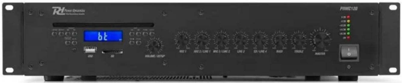
PRMC120 100V CD Mixer-Amplifier
Ref. nr.: 952.158
text_image
Power Dracula PRMC120 BL VOLUME / OUTPUT RDC 1 RDC 2/LINE 1 RDC 3/LINE 2 LINE 3 SD/LINE 4 RADD TINJALI MASTOSINSTRUCTION MANUAL GEBRUIKSAANWIJZING BEDIENUNGSANLEITUNG MANUAL DE INSTRUCCIONES MANUEL D'INSTRUCTIONS INSTRUKCJA OBSŁUGI NÁVOD K POUŽITÍ
V1.1
Congratulations to the purchase of this Power Dynamics product. Please read this manual thoroughly prior to using the unit in order to benefit fully from all features.
Read the manual prior to using the unit. Follow the instructions in order not to invalidate the warranty. Take all precautions to avoid fire and/or electrical shock. Repairs must only be carried out by a qualified technician in order to avoid electrical shock. Keep the manual for future reference.
- Prior to using the unit, please ask advice from a specialist. When the unit is switched on for the first time, some smell may occur. This is normal and will disappear after a while.
- The unit contains voltage carrying parts. Therefore do NOT open the housing.
- Do not place metal objects or pour liquids into the unit This may cause electrical shock and malfunction.
- Do not place the unit near heat sources such as radiators, etc. Do not place the unit on a vibrating surface. Do not cover the ventilation holes.
- The unit is not suitable for continuous use.
- Be careful with the mains lead and do not damage it. A faulty or damaged mains lead can cause electrical shock and malfunction.
- When unplugging the unit from a mains outlet, always pull the plug, never the lead.
- Do not plug or unplug the unit with wet hands.
- If the plug and/or the mains lead are damaged, they need to be replaced by a qualified technician.
- If the unit is damaged to such an extent that internal parts are visible, do NOT plug the unit into a mains outlet and DO NOT switch the unit on. Contact your dealer. Do NOT connect the unit to a rheostat or dimmer.
- To avoid fire and shock hazard, do not expose the unit to rain and moisture.
- All repairs should be carried out by a qualified technician only.
- Connect the unit to an earthed mains outlet (220-240Vac/50Hz) protected by a 10-16A fuse.
- During a thunderstorm or if the unit will not be used for a longer period of time, unplug it from the mains. The rule is: Unplug it from the mains when not in use.
- If the unit has not been used for a longer period of time, condensation may occur. Let the unit reach room temperature before you switch it on. Never use the unit in humid rooms or outdoors.
-
To prevent accidents in companies, you must follow the applicable guide lines and follow the instructions.
-
Do not repeatedly switch the fixture on and off. This shortens the life time.
- Keep the unit out of the reach of children. Do not leave the unit unattended.
- Do not use cleaning sprays to clean switches. The residues of these sprays cause deposits of dust and grease. In case of malfunction, always seek advice from a specialist.
- Do not force the controls.
- This unit is with speaker inside which can cause magnetic field. Keep this unit at least 60cm away from computer or TV.
- This unit is with built-in lead-acid rechargeable battery. Please recharge the battery every 3 months if you are not going to use the unit for a long period of time. Or the battery may be damaged.
- If the battery is damaged please replace with same specifications battery. And dispose the damaged battery environment friendly.
- If the unit has fallen, always have it checked by a qualified technician before you switch the unit on again.
- Do not use chemicals to clean the unit. They damage the varnish. Only clean the unit with a dry cloth.
- Keep away from electronic equipment that may cause interference.
- Only use original spares for repairs, otherwise serious damage and/or dangerous radiation may occur.
- Switch the unit off prior to unplugging it from the mains and/or other equipment. Unplug all leads and cables prior to moving the unit.
- Make sure that the mains lead cannot be damaged when people walk on it. Check the mains lead before every use for damages and faults!
- The mains voltage is 220-240Vac/50Hz. Check if power outlet match. If you travel, make sure that the mains voltage of the country is suitable for this unit.
- Keep the original packing material so that you can transport the unit in safe conditions.

This mark attracts the attention of the user to high voltages that are present inside the housing and that are of sufficient magnitude to cause a shock hazard.

This mark attracts the attention of the user to important instructions that are contained in the manual and that he should read and adhere to.
The unit has been certified CE. It is prohibited to make any changes to the unit. They would invalidate the CE certificate and their guarantee!
NOTE: To make sure that the unit will function normally, it must be used in rooms with a temperature between 5^ C/41°F and 35^ C/95°F.

Electric products must not be put into household waste. Please bring them to a recycling centre. Ask your local authorities or your dealer about the way to proceed. The specifications are typical. The actual values can slightly change from one unit to the other. Specifications can be changed without prior notice.
Do not attempt to make any repairs yourself. This would invalid your warranty. Do not make any changes to the unit. This would also invalid your warranty. The warranty is not applicable in case of accidents or damages caused by inappropriate use or disrespect of the warnings contained in this manual. Power Dynamics cannot be held responsible for personal injuries caused by a disrespect of the safety recommendations and warnings. This is also applicable to all damages in whatever form.
UNPACKING INSTRUCTION
CAUTION! Carefully unpack the box upon receipt. Check the contents to ensure that all parts are present and have been received in good condition. Notify the shipper immediately and retain packaging material if any parts appear damaged from shipping or the package itself shows signs of mishandling. Save the package and all packaging materials. If the product must be returned, it is important that the product is returned in the original factory box and packaging. If the device has been exposed to drastic temperature fluctuation (e.g. after transportation), do not switch it on immediately. The arising condensation water might damage your device. Leave the device switched off until it has reached room temperature.
POWER SUPPLY
The label on the back/under side of the product indicates the mains voltage to which it must be connected. Check that the mains voltage corresponds to this. Any other voltage than the one indicated may cause irreparable damage to the unit. The unit must also be connected directly to the mains voltage and no dimmer or adjustable power supply may be used.

Always connect the device to a protected circuit (circuit breaker or fuse). Make sure the device has an appropriate electrical ground to avoid the risk of electrocution or fire.
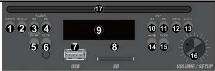
MEDIA PLAYER
- Power
Press to turn the MP3 player on/off
- Repeat
Press to change repeat modes (one/all/off)
- Previous folder
Press to select the previous folder
- Next folder
Press to select the next folder
- Shuffle
Press to choose between normal/random order
- Mute
Press to (un)mute the mp3 player
- USB port
Port for USB stick, USB card reader or compatible external hard drive for playback
- SD slot
Slot for SD card
- Display
LCD display showing track, elapsed time, etc
- Previous track
Press to change to previous track. Press and hold to rewind within a track
- Next track
Press to change to next track. Press and hold to fast forward within a track
- Program
Press to create a custom playlist
- Eject
Press to eject a CD
- Play/pause / stop
Press to start/resume or pause playback. Press and hold to stop play
- Mode
Press to change the mode (CD/BT/USB/SD)
- Volume/Setup
Rotate to adjust the volume
- CD Tray
FRONT PANEL
- MIC 1 volume level control
Rotate to adjust volume level control of mic 1 input.
Always turn back the level control to the minimum before switch on
- MIC 2/line 1 volume level control
Rotate to adjust volume level control of mic 2/ line 1 input.
Always turn back the level control to the minimum before switch on
- MIC 3/line 2 volume level control
Rotate to adjust volume level control of mic 3/line 2 input. Always turn back the level control to the minimum before switch on
- Line 3 volume level control
Rotate to adjust volume level control of line 3 input. Always turn back the level control to the minimum before switch on
- CD/line 4 volume level control
Rotate to adjust volume level control of CD/line 4 input. Always turn back the level control to the minimum before switch on
- Bass
Rotate to adjust the low (bass) frequencies, maximum increase +10 dB or maximum decrease of -10 dB
- Treble
Rotate to adjust the high (treble) frequencies, maximum increase +10 dB or maximum decrease of -10 dB
text_image
POWER REPEAT FOLDER 1234 DOUBLE ENTER MUTE 56 USB SD 17 9 SNP PROG ELECT 10111213 + - MOSR 1415 16 VOLUME / SETUP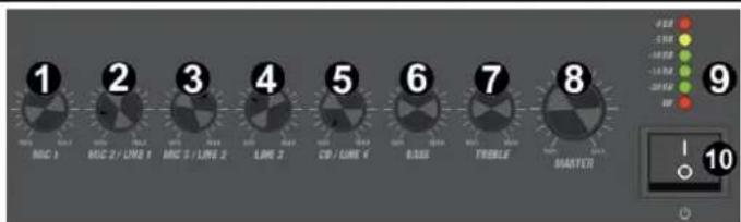
text_image
1 2 3 4 5 6 7 8 9 10- Master
Rotate to adjust the master volume. Always turn back the output volume control to the minimum before switch on
- Led indicators
The current system operation is indicated on the 6 digit LED bar graph. The LED's monitor shows the current output level within a range of -20 dB and 0 dB
- Power switch
This is the main power ON/OFF switch
REAR PANEL
- AC connection and fuse holder
This connector is used to supply main power to the unit. For instructions on how to change the fuse (bottom), see "Replacing the fuse"

text_image
P/BMC120 POWER IN 60 INPUT SPXUSER OUTPUT 4 5 6 7 8- DC 24V input
The main DC power supply (24V) has to be applied to this connector. This is a standby power inlet to connect a 24V battery
- Speaker output
Speaker output terminal for connecting speakers
- Line output
RCA line output connectors, for connecting additional amplifiers, etc
- Line input 3/4
RCA input connectors, for connecting audio units with line level output
- MIC/line input
6.3mm jack input connectors for connection audio units with line level output, or a microphone
- Dipswitches
Switches for selecting the preferred input channel, phantom power and VOX
| PIN | FUNCTION | ON | OFF |
| 1 | MIC 3/line 2 selection | Line 2 | MIC 3 |
| 2 | MIC 2/line 1 selection | Line 1 | MIC 2 |
| 3 | Phantom power | ON | OFF |
| 4 | VOX | ON | OFF |
- MIC 1 input
XLR input socket for connecting a microphone
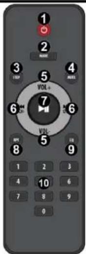
REMOTE CONTROL (ONLY FOR MP3 MODULE)
- Power
On/Off
- Mode
Press to change the mode (CD/BT/USB/SD)
- Stop
Press to stop playback
- Mute
Press to (un)mute the mp3 player
- Vol +/vol -
Press to increase/decrease volume
- Previous/Next
Press to go to previous or next track/channel
- Pause/Play
Press to pause/play MP3
- Repeat
Press to change repeat modes (one/all/off)
- EQ
Press to change EQ preset settings
- Numpad
Numbers (0-9) for direct selection
text_image
1 2 3 4 5 VOL+ 6 7 8 9 10 0OPERATION
When all connections to the amplifier are made, turn all rotary controls down and switch on the power and the power button LED will illuminate. Turn BASS and TREBLE controls to the 12 o'clock position (pointing straight up) and turn MASTER rotary control up part way for testing.
- Ensure a signal is being fed to one of the line inputs and gradually increase the volume control for that channel until the output is heard through the speakers. Turn up the MASTER to the maximum required volume level and reduce the channel volume control if necessary.
- Note: The initial test can be made using the built-in USB/SD audio player. The output of the amplifier is represented on the level meter LEDs. Anything longer than a short flash of this Clip LED may be indicating distortion or clipping of the output signal and the MASTER should be turned down.
- If a microphone is connected to MIC1 input, make sure it is switched on and if it requires phantom power, make sure this feature is enabled. Gradually increase its volume control whilst speaking into the microphone until the required volume level is reached. The microphone should not be able to “hear” the speakers, which can cause feedback (squealing or howling noise).
In addition to channel and MASTER volume controls, there are BASS and TREBLE EQ controls to adjust the tone of the overall output. At the 12 o'clock position, these controls are applying no effect to the signal (no boost or cut). Moving the BASS control clockwise boosts the low frequencies in the audio, whilst moving it anticlockwise will cut these low frequencies. Likewise, moving the TREBLE control clockwise boosts the high frequencies in the audio, whilst moving it anticlockwise will cut these high frequencies. Adjust these EQ controls to suit the type of audio signal or compensate for the room acoustics.
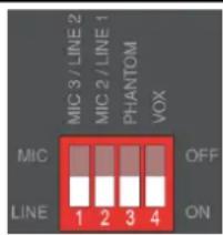
DIPSWITCHES
Adjacent to the XLR line microphone input is a bank of 4 DIP switches.
The right-hand switches are marked ‘Phantom’ and ‘VOX’. ‘Phantom’ sets phantom power for the corresponding XLR connector. When this is switched on you can use a condenser microphone. ‘VOX’ sets the voice-operated function to active.
The left-hand DIP switches are marked mic/line. They allow for either mic- or line level for the corresponding channels.
Noted: Be sure to make these DIP switch settings when the amplifier is switched off. Making any changes when the amplifier is powered up may cause loud bangs through the system which can damage the speakers.
text_image
MIC 3 / LINE 2 MIC 2 / LINE 1 PHANTOM VOX MIC OFF LINE 1 2 3 4 ONSPEAKER OUTPUT
For optimum performance it's important to use cables specifically designed for speaker use. Do not use shielded "guitar" signal cables for connection to these speakers.
Selection of the appropriate wire gauge is important for system operation.
A cable that is too light will result in amplifier power being wasted due to the series resistance of the cable. In addition, loss of low-frequency performance may be experienced due to a degraded damping factor.

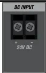
DC INPUT
The PRMC120 can be operated by 24V DC power for mobile applications (boats, fairgrounds etc.). For this type of application, connect the 24V DC power source to the 24V DC input terminals on the rear panel.
24 V DC Emergency alarm contacts terminal. If the fixed power supply fails, a mobile power supply can be connected to the 24V DC terminals to continue the power supply.
CONNECTING WITH BT
Before transmission between your BT device and the unit is possible, both devices must be coupled. This process is called "Pairing". The unit is served as a receiver, to receive the music stream to be played on the unit. If you have already coupled to a BT device before, this connection will be restored automatically when both devices are in range and BT operation has been selected on the unit. "Pairing" does not have to be repeated. This function may need to be activated in your BT device, however.
- Press [Mode] to enter BT mode.
- Turn on BT streaming on your device. The device will scan for pairable BT devices in the reception range.
- Select "PRMC120 Amplifier" from the list with found devices.
- Start playback on your BT device. Playback now takes place emitting sound from the unit.
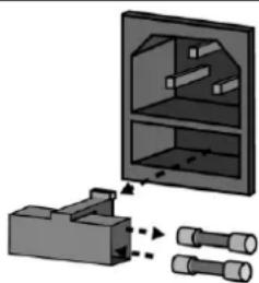
REPLACING THE FUSE
If the fuse is defective, replace the fuse with a fuse of the same type and value. Before replacing the fuse, unplug mains lead. Procedure:
Step 1: Open the fuse holder on the rear panel with a fitting screwdriver.
Step 2: Remove the old fuse from the fuse holder.
Step 3: Install the new fuse in the fuse holder.
Step 4: Replace the fuse holder in the housing.
natural_image
Diagram showing a mechanical assembly with two cylindrical components and a cabinet-like structure (no text or symbols)| PIN | FUNCTIE | ON | OFF |
| 1 | MIC 3/line 2 keuze | Line 2 | MIC 3 |
| 2 | MIC 2/line 1 keuze | Line 1 | MIC 2 |
| 3 | Phantom power | ON | OFF |
| 4 | VOX | ON | OFF |
- MIC 1 ingang
| PIN | FUNCTION | ON | OFF |
| 1 | MIC 3/line 2 selection | Line 2 | MIC 3 |
| 2 | MIC 2/line 1 selection | Line 1 | MIC 2 |
| 3 | Phantom power | ON | OFF |
| 4 | VOX | ON | OFF |
8. Eingang MIC 1
| PIN | FUNCTION | ON | OFF |
| 1 | MIC 3/line 2 selection | Line 2 | MIC 3 |
| 2 | MIC 2/line 1 selection | Line 1 | MIC 2 |
| 3 | Phantom power | ON | OFF |
| 4 | VOX | ON | OFF |
- Entrada MIC 1
natural_image
Diagram of a mechanical assembly with a cabinet and two cylindrical components, no visible text or symbols| PIN | FUNCTION | ON | OFF |
| 1 | MIC 3/line 2 selection | Line 2 | MIC 3 |
| 2 | MIC 2/line 1 selection | Line 1 | MIC 2 |
| 3 | Phantom power | ON | OFF |
| 4 | VOX | ON | OFF |
- Entrée MIC 1
DIPSWITCHES (INTERRUPTEURS)
REPLACEMENT DU FUSIBLE
text_image
PROMC120 POWER OF POWER 120 DC INPUT DC INPUT SPONSOR INPUT SPONSOR INPUT 4 5 6 7 8 LPG 1.0 LPG 2.0 LPG 3.0 LPG 4.0 LPG 5.0 LPG 6.0 LPG 7.0 LPG 8.0 LPG 9.0 LPG 10.0 LPG 11.0 LPG 12.0 LPG 13.0 LPG 14.0 LPG 15.0 LPG 16.0 LPG 17.0 LPG 18.0 LPG 19.0 LPG 20.0 LPG 21.0 LPG 22.0 LPG 23.0 LPG 24.0 LPG 25.0 LPG 26.0 LPG 27.0 LPG 28.0 LPG 29.0 LPG 30.0 LPG 31.0 LPG 32.0 LPG 33.0 LPG 34.0 LPG 35.0 LPG 36.0 LPG 37.0 LPG 38.0 LPG 39.0 LPG 40.0 LPG 41.0 LPG 42.0 LPG 43.0 LPG 44.0 LPG 45.0 LPG 46.0 LPG 47.0 LPG 48.0 LPG 49.0 LPG 50.0 LPG 51.0 LPG 52.0 LPG 53.0 LPG 54.0 LPG 55.0 LPG 56.0 LPG 57.0 LPG 58.0 LPG 59.0 LPG 60.0 LPG 61.0 LPG 62.0 LPG 63.0 LPG 64.0 LPG 65.0 LPG 66.0 LPG 67.0 LPG 68.0 LPG 69.0 LPG 70.0 LPG 71.0 LPG 72.0 LPG 73.0 LPG 74.0 LPG 75.0 LPG 76.0 LPG 77.0 LPG 78.0 LPG 79.0 LPG 80.0 LPG 81.0 LPG 82.0 LPG 83.0 LPG 84.0 LPG 85.0 LPG 86.0 LPG 87.0 LPG 88.0 LPG 89.0 LPG 90.0 LPG 91.0 LPG 92.0 LPG 93.0 LPG 94.0 LPG 95.0 LPG 96.0 LPG 97.0 LPG 98.0 LPG 99.0 LPG 100.0- Wyjście głośnikowe
| PIN | FUNCTION | ON | OFF |
| 1 | MIC 3/line 2 selection | Line 2 | MIC 3 |
| 2 | MIC 2/line 1 selection | Line 1 | MIC 2 |
| 3 | Phantom power | ON | OFF |
| 4 | VOX | ON | OFF |
- Wejście MIC 1
natural_image
Diagram of a mechanical assembly with two cylindrical components and a cabinet-like structure (no text or symbols)| PIN | FUNCTION | ON | OFF |
| 1 | MIC 3/line 2 selection | Line 2 | MIC 3 |
| 2 | MIC 2/line 1 selection | Line 1 | MIC 2 |
| 3 | Phantom power | ON | OFF |
| 4 | VOX | ON | OFF |
- Vstup MIC 1
Frequency response : 50Hz – 18KHz
Signal-to-noise ratio : >75dB
THD : <1%
Signal-to-noise ratio: Line : >85dB
Signal-to-noise ratio: Mic : >72dB
Input level: Line : 150-470mV, 10 kOhm
Input level: Mic. : 5-8mV, 600 Ohm
Power supply : 100-240VAC 50/60Hz
Dimensions (L x W x H) : 410 x 487 x 85mm
Weight : 11,40kg
The specifications are typical. The actual values can slightly change from one unit to the other. Specifications can be changed without prior notice.
The products referred to in this manual conform to the European Community Directives to which they are subject:
European Union
Tronios B.V.,
7602KR Almelo, The Netherlands
2014/35/EU
2014/30/EU
2011/65/EC
2014/53/EU

United Kingdom
Tronios Ltd.,
130 Harley Street,
London W1G 7JU, United Kingdom
S.I. 2016:1101
S.I. 2016:1091
S.I. 2012:3032
S.I. 2017:1206

Specifications and design are subject to change without prior notice.
www.tronios.com
Copyright © 2024 by TRONIOS the Netherlands