
BV 500 - Heating Master - Free user manual and instructions
Find the device manual for free BV 500 Master in PDF.

| Brand | Master |
| Model | BV 500 |
| Category | Heating |
| Product type | Combustion air heater (burner) |
| Fuel | Diesel or kerosene |
| Power supply | 230 V / 50 Hz |
| Usage | Professional, mobile and temporary (not for domestic use) |
| Operating modes | Heating, Ventilation |
| Air outlet temperature | Below 105°C in normal operation |
| Safety devices | Manual reset safety thermostat, temperature sensor, flame control |
| Maintenance | Annual cleaning of combustion chamber and exhaust circuit; cleaning of fan with compressed air |
| Repairability | Original spare parts, intervention by approved technical service center |
| Refueling | Only use the indicated fuel; store in a separate room |
| Safety distances | Front outlet: 2.5 m; sides, top and rear: 1.5 m from flammable materials |
| Required electrical installation | Grounding, differential magnetothermal circuit breaker, disconnecting switch |
| Compliance | European Directive 2012/19/EU (WEEE) |
| Allowed extension cord | Only with ground cable |
| Burner | Dedicated, with specific nozzle; do not increase power |
| Exhaust chimney | Connected to a chimney or flue, preferably vertical steel |
Frequently Asked Questions - BV 500 Master
User questions about BV 500 Master
0 question about this device. Answer the ones you know or ask your own.
Ask a new question about this device
Download the instructions for your Heating in PDF format for free! Find your manual BV 500 - Master and take your electronic device back in hand. On this page are published all the documents necessary for the use of your device. BV 500 by Master.
USER MANUAL BV 500 Master
natural_image
Icon of an open book with an exclamation mark, enclosed in a diamond shape with a yellow diagonal stripe (no text or symbols)USER AND MAINTENANCE MANUAL
BV 500-13 R
| en | it | de | es | fr | da | fi | no | pl | ru | cs | hu |
NOTE:
TECHNICAL DATA TABLE - TABELLA DATI TECNICI - TECHNISCHE DATENTABELLE - TABLA DE DATOS TÉCNICOS - TABLEAU DES DONNÉES TECHNIQUES - TABEL TECHNISCHE GEGEVENS - TABELA DE DADOS TÉCNICOS - TEKNISK DATATABEL - TEKNISTEN TIETOJEN TAULUKKO - TABELL FOR TEKNISKE DATA - TABELL MED TEKNISKA EGENSKAPER -
TABELA DANYCH TECHNICZNYCH - ТАБЛИЦЕ ТЕХНИЧЕСКИХ ДАННЫХ
- TABULKA TECHNICKÝCH ÚDAJŮ - MŰSZAKI ADATOK TÁBLÁZATA
- TEHNIČNI PODATKI - TEKNÍK VERÍLER TABLOSUNDA - TABLICI S
TEHNIČKIM PODACIMA - TECHNINIŲ DUOMENŲ LENTELĖJE - TEHNISKO
DATU TABULA - TEHNILISTE ANDMETE TABEL - TABELUL CU DATE
ТЕНNICE - TABUL'KA TECHNICKÝCH ÚDAJOV - ТАБЛИЦА ТЕХНИЧЕСКИ ДАННИ - ТАБЛИЦІ ТЕХНІЧНИХ ДАНИХ - TABELI SA TEHNIČKİM PODACIMA
IMPORTANT: In order to have a correct function you must use an electrical generator in class G3 or more (frequency variation ±1%, tension variation ±2%). The maximum power of electrical generator must be three time the nominal power of device that you must connect.
NOTE:
PICTURES - FIGURE - ABBILDUNGEN - FIGURAS - FIGURES - FIGU-
REN - FIGURAS - FIGURER - KUVAT - FIGURER - FIGUR - RYSUN-
natural_image
Technical line drawing of a cylindrical industrial machine mounted on a platform (no text or symbols)1
Vers. B
natural_image
Line drawing of a cylindrical industrial machine with wheels and a handle (no text or symbols)1
PICTURES - FIGURE - ABBILDUNGEN - FIGURAS - FIGURES - FIGUREN - FIGURAS - FIGURER - KUVAT - FIGURER - FIGUR - RYSUN-KI - РИСУНКИ - OBRÁZKY - ÁBRÁK - SLIKE - ŞEKİLLER - SLIKE - PAVEIKSLĖLIAI - ATTĖLI - JOONISED - IMAGINI - OBRÁZKY - ФИГУРА - МАЛЮНКИ - SLIKE - EİKONEΣ - 图 - СУРЕТТЕР
natural_image
Line drawing of a mechanical cart with a large cylindrical component, no text or symbols present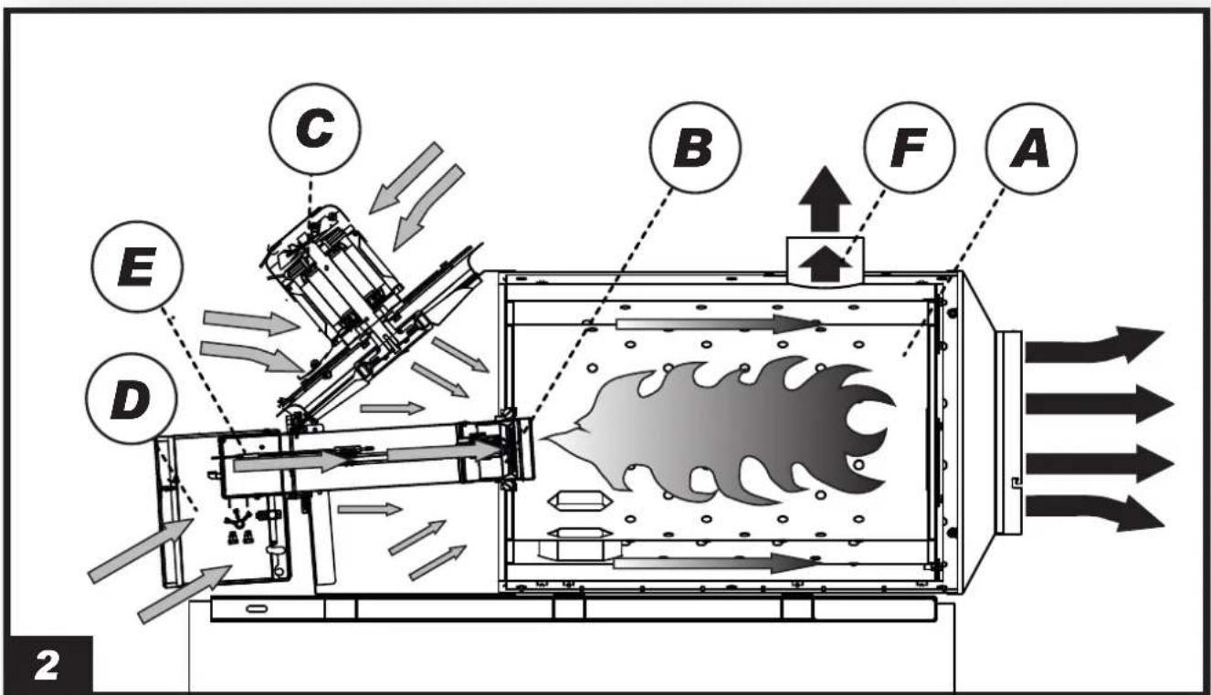
PICTURES - FIGURE - ABBILDUNGEN - FIGURAS - FIGURES - FIGUREN - FIGURAS - FIGURER - KUVAT - FIGURER - FIGUR - RYSUNKI - РИСУНКИ - OBRÁZKY - ÁBRÁK - SLIKE - ŞEKİLLER - SLIKE - PAVEIKSLÉLIAI - ATTËLI - JOONISED - IMAGINI - OBRÁZKY - ФИГУРА - МАЛЮНКИ - SLIKE - EIKONEΣ - 图 - СУРЕТТЕР
natural_image
Mechanical assembly diagram showing a rotating motor with directional arrows indicating motion (no text or symbols)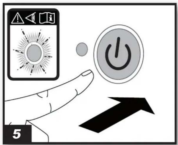
natural_image
Illustration of a hand pointing at a mechanical component with an arrow indicating rotation (no text or symbols present)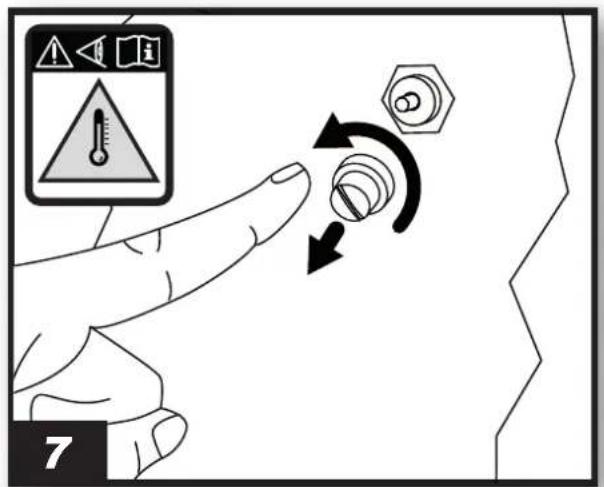
PICTURES - FIGURE - ABBILDUNGEN - FIGURAS - FIGURES - FIGUREN - FIGURAS - FIGURER - KUVAT - FIGURER - FIGUR - RYSUN-KI - РИСУНКИ - OBRÁZKY - ÁBRÁK - SLIKE - ŞEKİLLER - SLIKE - PAVEIKSLĖLIAI - ATTĖLI - JOONISED - IMAGINI - OBRÁZKY - ФИГУРА - МАЛЮНКИ - SLIKE - EİKONEΣ - 图 - СУРЕТТЕР
natural_image
Technical line drawing of a mechanical clamp or connector assembly (no text or symbols)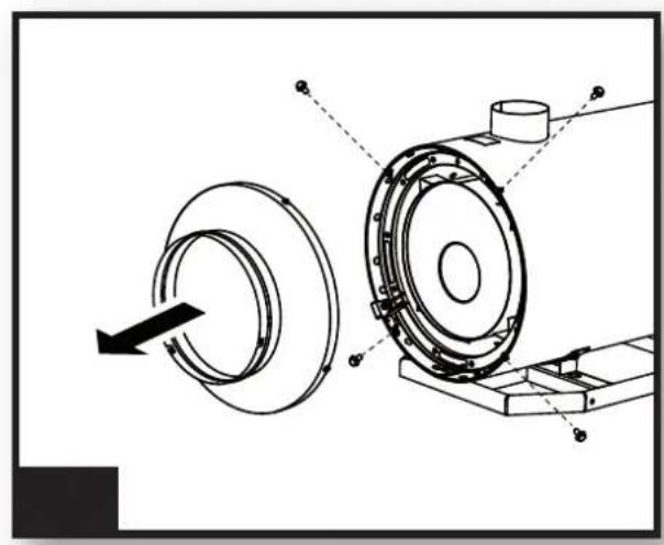
natural_image
Technical diagram of a mechanical assembly showing a rotating component and housing (no text or symbols)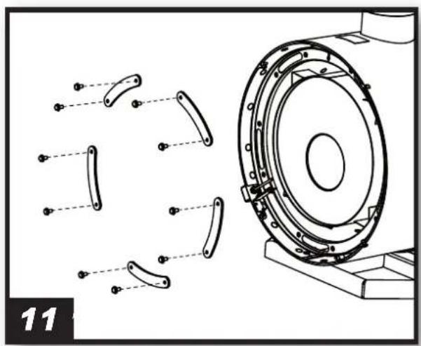
natural_image
Technical line drawing of a mechanical assembly with multiple curved components and a central circular component (no text or symbols)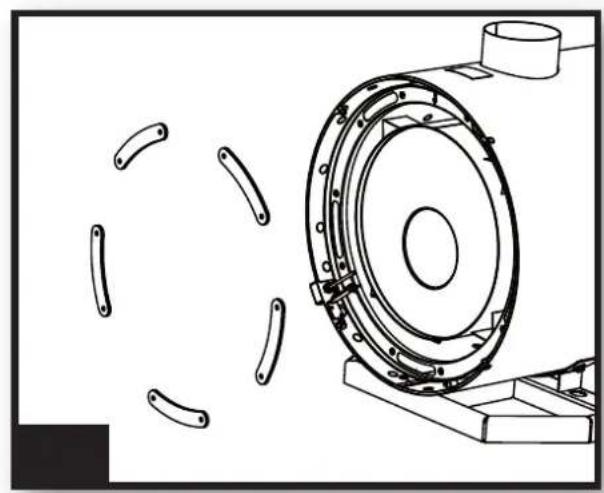
natural_image
Technical line drawing of a mechanical component with multiple curved components and a central circular housing (no text or symbols)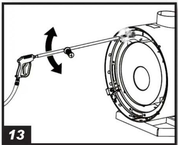
natural_image
Diagram of a fuel pump operating on a rotating mechanical component, showing rotational flow direction (no text or symbols)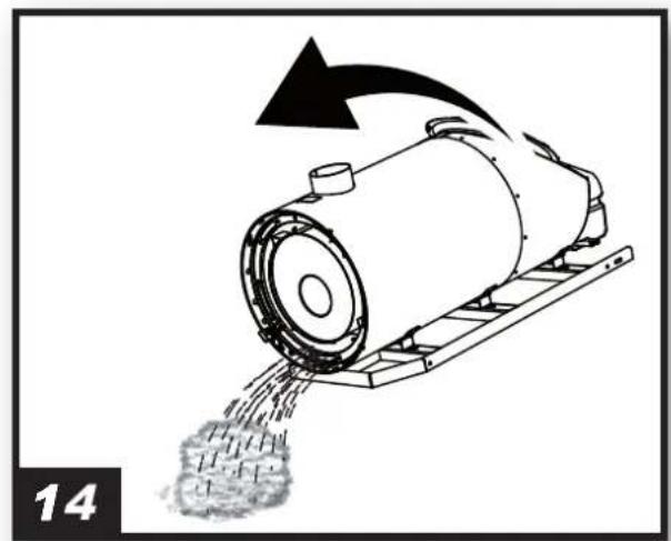
natural_image
Diagram of a mechanical device emitting granular material, with an arrow indicating motion direction (no text or symbols)IMPORTANT: READ AND UNDERSTAND THIS OPERATIONAL MANUAL PRIOR TO ASSEMBLING, STARTING UP OR CONDUCTING MAINTENANCE ON THIS HEATER. USING THE HEATER INCORRECTLY CAN CAUSE SERIOUS OR FATAL INJURIES. KEEP THIS MANUAL FOR FURTHER REFERENCE.
1. DESCRIPTION
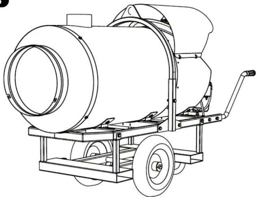
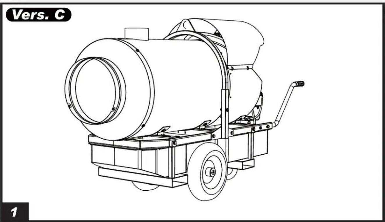
(Pic. 1) This heater is equipped with a dedicated burner, a combustion chamber with flue gas evacuation to the outside and a high performance hot air handling fan. The air is heated by thermal energy produced by combustion transmitted by means of thermal exchange with the metal surfaces of the combustion chamber and flue gas pass. The path of the ventilated air and flue gas is separated by metal surfaces joined by welds and sealing gaskets. The combustion products are conveyed to an exhaust duct. This must be connected to a chimney or flue large enough to evacuate the flue gas. Combustion air, namely the air required for combustion, is drawn directly from the burner, which draws it from the surrounding environment. Its size and work conditions must guarantee an appropriate air exchange.
2. SAFETY INFORMATION WARNINGS

IMPORTANT: This air heater has been designed for mobile and temporary professional applications. It has not been designed for domestic use nor for thermal comfort of human.

IMPORTANT: This appliance is not suitable for use by persons (including children) with reduced physical, sensory or mental capacities or who lack experience or knowledge unless supervised by a person responsible for their safety. Children must be supervised to make sure they do not play with the appliance.

DANGER: Suffocation by carbon monoxide can be fatal.
The first symptoms of suffocation by carbon monoxide are similar to those of flu with headache, light-headedness and/or nausea. These symptoms could be caused by faulty operation of the heater. IF THESE SYMPTOMS OCCUR, GO OUTDOORS IMMEDIATELY and have the heater repaired by an authorised technical support centre.
▶▶2.1. REFUELLING:
••2.1.1. Personnel appointed to carry out refuelling must be qualified and fully familiar with the manufacturer's instructions and current regulations on how to refuel heaters safely.
••2.1.2. Only use the type of fuel expressly specified on the technical data label applied to the heater.
•••2.1.3. The tanks used to store the fuel must be stored in a separate place.
••2.1.4. Fuel tanks must be kept at a minimum distance from the heater, in accordance with current standards.
••2.1.5. The fuel must be stored in an area where the floor does not allow it to penetrate or drip onto flames underneath it, which may ignite the fuel.
••2.1.6. The fuel must be stored in accordance with current regulations.
▶▶2.2. SAFETY:
••2.2.1. Check that the fire-fighting equipment is available and suitable to the potential of the heater.
••2.2.2. Never use the heater in areas with petrol, paint solvents or other highly flammable vapours.
••2.2.3. Comply with all local legislation and current regulations when using the heater.
••2.2.4. Heaters used near tarpaulins, curtains or other similar covering materials must be a safe distance from them. It is advised to use fireproof covering material.
••2.2.5. Only use in well-ventilated areas. Set-up a suitable opening in line with current standards, with the purpose of introducing fresh air from outdoors.
••2.2.6. Power the heater only with current that has the voltage and frequency values specified on the technical data label applied to the heater.
•••2.2.7. Check correct earthing.
••2.2.8. Only use extension cables that are earthed.
••2.2.9. The electric power line of the heater must be equipped with an earthing system, residual current device and cut-off switch.
••2.2.10. Recommended safety distances between the heater and flammable substances: front output = 2,5 m (8.5 ft.); on the side, at the top and at the back = 1,5 m (5 ft.).
••2.2.11. Avoid fire hazards by placing the hot or functioning heater on a steady level surface.
•••2.2.12. Keep animals at a safe distance from the heater.
••2.2.13. Disconnect the heater from the electric power supply when not in use.
••2.2.14. When it is controlled by a thermostat, the heater can turn on at any time.
••2.2.15. Never use the heater in frequently used rooms.
•••2.2.16. Never block the heater's air vent (rear) or the air outlet (front).
••2.2.17. Never handle or conduct maintenance on the heater when it is hot, connected to the power supply or in operation.
••2.2.18. Only use original kits to direct the air coming in and/or going out (where applicable).
••2.2.19. Keep the hot parts of the heater at a suitable distance from inflammable or thermolabile materials (including the power supply cable).
••2.2.20. If the power supply cable is damaged, it must be replaced by an authorised technical support centre to prevent any risk.
••2.2.21. Use original spare parts when replacing the burner, strictly complying with indications regarding capacity, type of nozzles and pump pressure. An increase in burner power could damage the heater.
3. UNPACKING
WARNING: The packaging material is not a toy. Keep the plastic bag out of the reach of children; danger of suffocation!
••3.1. Remove all packaging materials used to package and ship the heater. Dispose of them in compliance with current standards.
••3.2. The heater is placed on a platform. Lift it delicately using hooks and chains. Use the holes on the structure to lift the heater.
••3.3. Check for any damage undergone during transport. If the heater appears to be damaged, immediately inform the authorised technical support centre.
4. OPERATING PRINCIPLES
A. Combustion chamber, B. Combustion head, C. Fan, D. Burner, E. Control equipment, F. Chimney.
(Pic. 2) The burner pump aspires the fuel from the tank and sends it to the pressurised nozzle where it is nebulised and mixed with comburent air in the combustion chamber. A spark triggers combustion while the waste fumes are expelled from the chimney. A series of sensors constantly checks the correct operation of the heater, stopping the cycle in the case of a fault. The fan, located at the rear of the heater, cools the combustion chamber and the flue gas pass, transferring the heat from the latter into the environment.
5. INSTALLATION INSTRUCTIONS
CAUTION: Closely follow all the operations described in this paragraph. Installation must only be carried out by professionally qualified personnel.
▶▶5.1. ELECTRICAL CONNECTIONS:
CAUTION: The electric power line of the heater must be equipped with an earthing system, residual current device and cut-off switch.
The standard supply of the heater includes all the control and safety devices essential for its proper operation: electric panel, burner, manually reset safety thermostat are already connected.
During installation, prepare the power supply connection with cables having an appropriate cross-section in compliance with national standards in force and the technical data label applied to the heater.
NOTE: CHECK THE ELECTRIC CONNECTIONS BEFORE STARTING THE HEATER.
▶▶5.2. INLET AND/OR OUTLET AIR DUCTING CONNECTION (where applicable):
USE ONLY ORIGINAL KITS FOR DUCTING.
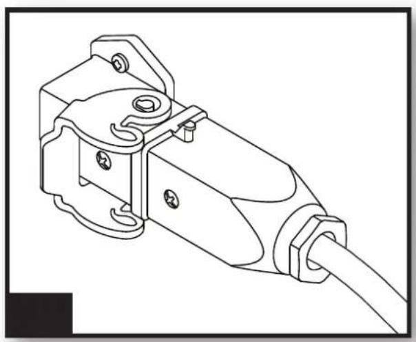
The inlet and outlet air ducting can be installed with the specific clamp or quick coupling.
▶▶5.3. FLUE GAS EXHAUST CONNECTION:
Thermal efficiency and appropriate operation are directly linked to the correct draught of the flue gas exhaust chimney. It is recommended not to make elbows, which could get clogged, or reductions in the cross-section of the flue gas exhaust chimney. If the heater is not connected to an external flue gas exhaust chimney, it must be provided with an essentially vertical steel flue gas exhaust and a draught regulator, respecting the specifications provided in this technical manual.
6. FUEL
WARNING: The heater only works with DIESEL or KEROSENE.
Only use diesel or kerosene. To avoid any fire or explosion hazard, never use petrol, naphtha, solvents for paints, alcohol or other highly inflammable fuels.
Use non-toxic, anti-freeze additives in case of very low temperatures.
It is recommended to use winter diesel oil below 5^ C ( 41^ F).
7. OPERATION
WARNING: Carefully read the “SAFETY INFORMATION” before switching on the heater.
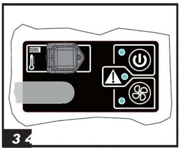
IDENTIFY THE CONTROL PANEL OF THE HEATER (Pic 3).
▶▶7.1. SWITCH-ON:
••7.1.1. Check if there is any fuel in the circuit.
…7.1.2. Connect the heater to the mains.
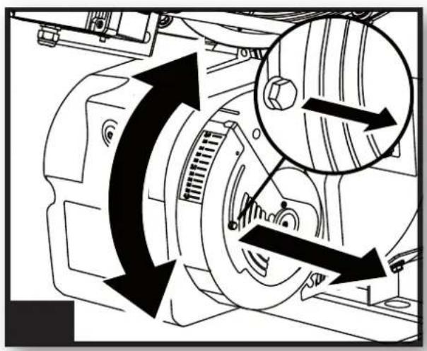
••7.1.3. Adjust the air damper of the burner according to needs (Pic. 4).
▶▶7.2. START-UP IN HEATING MODE:
Press the on-off button (Pic. 5) (the burner starts first and after about one minute starts ventilation).
NOTE: THE HEATER HAS A SENSOR THAT CONSTANTLY MONITORS THE OUTLET AIR TEMPERATURE [FOR NORMAL OPERATION, THE OUTLET AIR TEMPERATURE MUST BE BELOW 105°C (221°F)]. IF THE OUTLET AIR TEMPERATURE EXCEEDS 105°C (221°F), THE HEATER TURNS OFF THE BURNER. WHEN THE TEMPERATURE RETURNS BELOW 105°C (221°F), THE BURNER AUTOMATICALLY REACTIVATES. UNDER 105°C (221°F) THE HEATER MODULATES VENTILATION TO ENSURE THE BEST OUTLET AIR TEMPERATURE, IN RELATION TO THE ENVIRONMENTAL CONDITIONS DETECTED.
▶▶7.3. START-UP IN VENTILATION MODE:
IMPORTANT: Never unplug the heater to switch it off.
IMPORTANT: Never unplug the heater before it is completely off.
Press the off button (Pic. 5), and wait for the heater to stop completely. When the outlet air temperature drops below 50^ C ( 122^ F), the fan turns off and the luminous signal of the button turns on to indicate the presence of voltage (stand-by condition).
▶▶7.5. RESET:
During normal operation, the heater could block (for example when fuel is missing). In this case the heater must be reset:
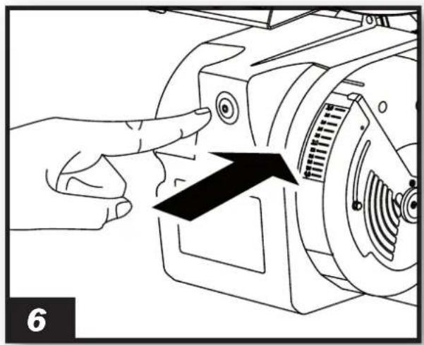
-7.5.1. RESETTING THE BURNER: If the burner is blocked, the indicator light on the control panel turns on. Identify and remove the cause of the block. To reactivate the burner, press the reset button on it for at least 10 seconds (Pic. 6).
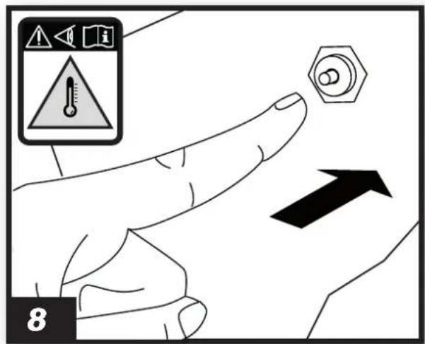
-7.5.2. RESETTING THE SAFETY THERMOSTAT: Safety thermostat operation is identified by an indicator light (Pic. 7-8). Identify and remove the cause that triggered the safety thermostat. Press the reset button located at the back of the heater all the way.
8. CONNECTING THE ROOM THERMOSTAT
To connect the room thermostat, remove the plug of the dedicated socket and connect the room thermostat (optional) (Pic. 9).
9. STORAGE AND TRANSPORT
Before handling, the heater must be switched off following the proper procedure with the power disconnected. Wait for the heater to cool.
Before handling, make sure that the support is used to move the heater is capable of bearing its weight (the weight is displayed on the technical specification of the appliance). Do not attempt to lift or move the heater without the aid of suitable equipment (this operation must be carried out with the utmost attention to avoid personal harm or damage to the heater).
10. MAINTENANCE
IMPORTANT: Before performing any maintenance or repairs, disconnect the power cable and make sure the heater is cold.
Periodic maintenance is recommended to keep the heater in good condition, avoiding possible failures or faults as far as possible.
▶▶10.1. CLEANING THE COMBUSTION CHAMBER:
IMPORTANT: This operation can be carried out by contacting the authorised technical support centre.
It is recommended to clean the combustion chamber and flue gas duct at least once a year or when required to avoid problems regarding chimney draught and combustion. The combustion chamber is cleaned through the five inspection openings on the front of the heater.
Closely follow this sequence to perform cleaning (keep the screws and washers with care):
••10.1.1. Remove the air ducting cone by removing the screws which secure it to the heater (Pic. 10).
••10.1.2. Remove the plates, which close the inspection openings, by removing the screws (Pic. 11).
••10.1.3. Remove the gaskets installed and do not reuse them. Only use new and original gaskets (Pic. 12).
•••10.1.4. Spray high pressure water inside the chamber through the inspection openings (Pic. 13). When washing, move the nozzle in various positions so the water
reaches all the slots of the combustion chamber.
••10.1.5. Lift the combustion chamber from the back to empty as much water as possible from inside the chamber (this operation must be carried out with the utmost attention to avoid personal harm or damaging the heater) (Pic. 14).
•••10.1.6. Reassemble the heater performing the sequence of operations in the opposite order, replacing the gaskets with original spare parts.
NOTE: BEFORE SWITCHING THE HEATER BACK ON, MAKE SURE AS MUCH WATER AS POSSIBLE HAS BEEN ELIMINATED FROM INSIDE THE COMBUSTION CHAMBER TO AVOID SERIOUS DAMAGE.
▶▶10.2. CLEANING THE FAN:
Use compressed air for routine cleaning of the fan, blowing the air through the rear grille.
▶▶10.3. CLEANING THE BURNER:
IMPORTANT: This operation can be carried out by contacting the authorised technical support centre.
Read and understand the specific manual to clean the burner.
11. PREVENTIVE MAINTENANCE SCHEDULE
WARNING: BEFORE PERFORMING ANY MAINTENANCE OR REPAIRS, DISCONNECT THE POWER CABLE AND MAKE SURE THAT THE HEATER IS COLD.
| COMPONENT | MAINTENANCE FREQUENCY | MAINTENANCE PROCEDURE |
| Safety thermostat | Yearly check and/or when required | Contact the authorised technical support centre |
| Nozzle | Replace yearly and/or when required | Contact the authorised technical support centre |
| Electrical system | Yearly check and/or when required | Contact the authorised technical support centre |
| Fan | Yearly cleaning and/or when required | Contact the authorised technical support centre |
| Motor | Yearly check and/or when required | Contact the authorised technical support centre |
| Fuel pump | Yearly check and/or when required | Contact the authorised technical support centre |
| Combustion chamber | Yearly check and/or when required | Contact the authorised technical support centre |
12. TROUBLESHOOTING
| PROBLEM | POSSIBLE CAUSE POSSIBLE SOLUTION | |
| The heater does not start or does not remain on | 1. No power supply2. Interrupted power cable3. Electronics need to be reset or are faulty4. Incorrect setting of the room thermostat (if applicable)5. No fuel6. Foreign substances in the fuel circuit | 1a. Check that there is electric power1b. Check that the heater is connected to the correct power supply1c. Contact the authorised technical support centre2. Contact the authorised technical support centre3a. Reset the heater3b. Contact the authorised technical support centre4. Set the room thermostat to a temperature higher than the temperature of the working environment5. Refuel and, if necessary, reset the heater6. Contact the authorised technical support centre |
| The heater generates smoke during operation | 1. Foreign substances in the fuel circuit2. Obstruction of inlet air vent | 1. Contact the authorised technical support centre2. Remove all possible obstructions from the rear grille |
| The heater does not switch off | 1. Electronics are faulty 1. Contact the authorised technical support centre | |
IMPORTANTE: LEGGERE E COMPRENDERE QUESTO MANUALE OPERATIVO PRIMA DI EFFETTUARE L'ASSEMBLAGGIO, LA MESSA IN FUNZIONE O LA MANUTENZIONE DI QUESTO RISCALDATORE. L'USO ERRATO DEL RISCALDATORE PUÒ CAUSARE LESIONI GRAVI O FATALI. CONSERVARE QUESTO MANUALE A TITOLO DI FUTURO RIFERIMENTO.
1. DESCRIZIONE
PROBLEMA POSSIBLE CAUSE POSSIBLE SOLUTIONE
▶▶2.1. NACHFÜLLEN DES BRENNSTOFFS:
▶▶7.1. INBETRIEBNAHME:
▶▶2.2. BEZPIECZEŃSTWO:
PROBLEM POSSIBLE CAUSE POSSIBLE SOLUTION
ALARM DIAGNOSTICS CONTROL DISPLAY
natural_image
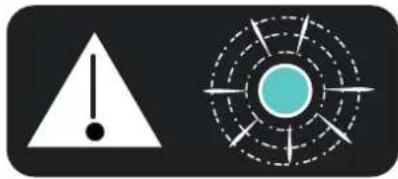
Two warning symbols: a triangular warning triangle with an exclamation mark and a circular target with radial lines (no text or labels)FLASHES Period A - Burner Lockout

bar
| Time | Value | |---|---| | 0,2 | 1 | | 2,0 sec | 1 | | 0,2 | 0 | | 0,2 | 1 | | 0,2 | 1 | | 0,2 | 0 | | 2,0 sec | 1 |FLASHES Period B – 120 sec After Start, Outlet Temperature < Ambient Temperature plus 5°C

bar
| Time (sec) | Duration | | :--- | :--- | | 1,0 | 1,0 sec | | 1,0 | 1,0 sec | | 1,0 | 1,0 sec | | 1,0 | 1,0 sec | | 1,0 | 1,0 sec |FLASHES Period D – If Is Present Ambient Thermostat

bar
| Time (sec) | Value | |---|---| | 3,0 sec | 3,0 sec | | 3,0 sec | 3,0 sec |NOTE:
NOTE:
CE CONFORMITY CERTIFICATE
CE
CE CONFORMITY CERTIFICATE - DICHIARAZIONE DI CONFORMITÀ CE - EG-KONFORMITÄTSERKLÄRUNG - DECLARACIÓN DE CONFORMIDAD CE - DECLARATION DE CONFORMITE CE - EG-CONFORMITEITVERKLARING - DECLARAÇÃO DE CONFORMIDADE CE - EU-OVERENSSTEMMELSESERKLÆRING - EY-VAATIMUSTENMUKAISUUSVAKUUTUS - CE-SAMSVARSERKLÆRING - EG-FÖRSÄKRAN OM ÖVERENSSTÄMMELSE - DEKLARACJA ZGODNOŚCI WE - ДЕКЛАРАЦИЯ О COOTBETCTВИИ CE - PROHLÁŠENÍ O SHODĚ CE - EK MEGFELELŐSÉGI NYILATKOZAT - IZJAVA O SKLADNOSTI IN OZNAKA CE - CE UYGUNLUK BEYANI - IZJAVA CE O SUKLADNOSTI - ES ATITIKTIES DEKLARACIJA - EK ATBILSTĪBAS - DEKLARĀCIJA - EÜ VASTAVUSDEKLARATSIOON - DECLARAȚIE DE CONFORMITATE CE - PREHLÁSENIE O ZHODE CE - ДЕКЛАРАЦИЯ ЗА СЪВМЕСТИМОСТ CE - ДЕКЛАРАЦИЯ ВІДПОВІДНОСТИ CE - IZJAVA CE O PRIKLADNOSTI ΔΗΛΩΣΗ ΣΥΜΜΟΡΦΩΣΗΣ CE - CE 符合性声明
DANTHERM S.p.A. Via Gardesana 11, -37010- Pastrengo (VR), ITALY
Product: - Prodotto: - Produkt: - Producto: - Produit: - Product: - Produto: - Produkt: - Tuote: - Produkt: - Produkt: - Produkt: - Изделие: - Výrobek: - Termék: - Izdelek: - Ürün: - Proizvod: - Gaminys: - Ierīce: - Toode: - Produsul: - Výrobok: - Продукт: - Виріб: - Proizvod: - Проїóv: - 产品:
BV 500-13 R
We declare that it is compliant with: - Si dichiara che è conforme a: - Es wird als konform mit den folgenden Normen erklärt: - Se declara que está en conformidad con: - Nous déclarons sa conformité à: - Hierbij wordt verklaard dat het product conform is met: - Declara-se que está em conformidade com: - Vi erklærer at produktet er i overensstemmelse med: - Vakuutetaan olevan yhdenmukainen: - Man erklærer at apparatet er i overensstemmelse med: - Härmed intygas det att produkten är förenlig med följande: - Oświadczca się, że jest zgodny z: - Заявляем о соответствии требованиям: - Prohlašuje se, że je v souladu s: - Kijelentjük, hogy a termék megfelel az alábbiaknak: - Izpolnjuje zahteve: - Aşağıdaki standartlara uygun olduğunu beyan ederiz: - Izjavljuje se da je u skladu s: - Pareiškiame, kad atitinka: - Tiek deklarēts, ka atbilst: - Käesolevaga deklareeritakse, et toode vastab: - Declarām că este conform următoarelor: - Prehlasuje sa, że je v súlade s: - Декларира се че отговаря на: - Відповідає вимогам: - Izjavljuje se da je u skladu s: - Δηλώνουμε ότι είναι σύμφωνο με: - 兹证明符合:
2014/30/EU, 2014/35/EU
EN 62233:2008, EN 61000-3-2:2014, EN 61000-3-3:2013, EN 55014-1:2006/A2:2011, EN 55014-2:2015, EN 60335-1:2012/A11:2014, EN 60335-2-102:2016
Pastrengo, 2023

natural_image
Abstract blue line drawing with no text or symbols▶en - DISPOSAL OF THE PRODUCT
-This product has been designed and manufactured with top-quality materials and components, which can be re-cycled and re-used. -When a crossed-wheely bin symbol is attached to the product, it means that the product is protected by the, 2012/19/UE European Directive.
-Please obtain information regarding the local differentiated collection system for electrical and electronic products.
-Respect local Standards in force and do not dispose of old products as normal domestic waste. Correct disposal of the product helps to prevent possible negative consequences for health, the environment and mankind.
▶ Iv - PRODUKTA IZNĪCINĀŠANA
natural_image
Abstract geometric composition with yellow and black blocks (no text or symbols)Dantherm S.p.A.
Via Gardesana 11
37010 Pastrengo (VR)
Italy
t.: +39 045 6770533
e.: info.it@danthermgroup.com

DOWNLOAD CATALOGUE

SEND US YOUR FEEDBACK

REGISTER FOR 3-YEAR WARRANTEE